
 Open Access Article
 This Open Access Article is licensed under a Creative Commons Attribution-Non Commercial 3.0 Unported Licence
Atomic surface of quartz glass induced by photocatalytic green chemical mechanical polishing using the developed SiO2@TiO2 core–shell slurry
Yuanhang
Fan
a,
Zhenyu
Zhang
 *a,
Jiaxin
Yu
*b,
Xingqiao
Deng
*c,
Chunjing
Shi
d,
Hongxiu
Zhou
e,
Fanning
Meng
d and
Junyuan
Feng
d
*a,
Jiaxin
Yu
*b,
Xingqiao
Deng
*c,
Chunjing
Shi
d,
Hongxiu
Zhou
e,
Fanning
Meng
d and
Junyuan
Feng
d
aState Key Laboratory of High-performance Precision Manufacturing, Dalian University of Technology, Dalian 116024, China. E-mail: zzy@dlut.edu.cn
bSchool of Manufacturing Science and Engineering, Southwest University of Science and Technology, Mianyang 621010, China. E-mail: yujiaxin@swust.edu.cn
cSchool of Mechanical and Electrical Engineering, Chengdu University of Technology, Chengdu 610059, China. E-mail: dengxingqiao19@cdut.edu.cn
dSchool of Mechanical Engineering, Hangzhou Dianzi University, Hangzhou 310018, China
eSchool of Energy and Power Engineering, Dalian University of Technology, Dalian 116024, China
First published on 12th December 2023
Abstract
High-performance devices of quartz glass demand an atomic surface, which induces a challenge for chemical mechanical polishing (CMP) with a high material removal rate (MRR). Moreover, traditional CMP usually employs toxic and corrosive slurries, leading to the pollution of the environment. To overcome these challenges, a novel green photocatalytic CMP is proposed. In the CMP, SiO2@TiO2 core–shell abrasives were developed, and the CMP slurry included the developed abrasives, sodium carbonate, hydrogen peroxide and sorbitol. After photocatalytic CMP, the surface roughness Sa of quartz glass is 0.185 nm, with a scanning area of 50 × 50 μm2, and the MRR is 8.64 μm h−1. To the best of our knowledge, the MRR is the highest on such a big area of atomic surface for quartz glass. X-ray photoelectron spectroscopy reveals that SiO2@TiO2 core–shell abrasives were used as photocatalysts motivated by simulated solar light, generating electrons and holes and producing hydroxyl radicals through hydrogen peroxide. As a result, OH− could combine with Si atoms on the surface of quartz glass, forming Si–OH–Si bonds. Then the formed bonds were removed based on the balance between chemical and mechanical functions. The proposed CMP, developed SiO2@TiO2 abrasives and slurry provide new insights to achieve an atomic surface of quartz glass with a high MRR.
1. Introduction
Quartz glass, primarily composed of SiO2, is an amorphous solid that is colorless, transparent, and possesses a hard texture.1,2 At the microscopic level, the interior of quartz glass forms a stable network structure woven from tetrahedra consisting of silicon and oxygen atoms. At the macroscopic level, this results in stable chemical characteristics and outstanding physical properties, including outstanding heat resistance, dimensional stability, high-temperature tolerance, and excellent light transmittance.3,4 Consequently, quartz glass is extensively used in high-tech industries such as optoelectronic systems, semiconductors, aerospace, etc.5,6 In these advanced applications, quartz glass needs to meet stringent requirements. As an optical component, it must exhibit minimal subsurface damage and achieve an atomic-level super-smooth surface.7,8 The improvement of surface quality in quartz glass primarily relies on two key processes: grinding and polishing.9 Chemical mechanical polishing (CMP) has emerged as the primary processing method for quartz glass due to its high removal rate and low surface roughness.10–12 However, CMP slurry, a crucial material in optical element fabrications, presents distinct challenges. It demands a high level of expertise, involves significant investment risks, has a lengthy technology accumulation cycle, and relies heavily on economies of scale. Consequently, the development of CMP slurry faces substantial challenges. For decades, tremendous efforts have been dedicated to exploring CMP slurry, mainly composed of abrasives, pH adjusters, oxidizers, surface active agents, and various other components.13 Among these constituents, abrasives have been recognized as essential candidates for polishing due to their surface chemical and frictional properties.14,15 SiO2 and CeO2 stand out as the most frequently employed abrasives.16 To enhance the precision polishing performance of these abrasives, additional agents such as surfactants and dispersants including PAMS,17 sodium hexametaphosphate, SDBS, and triethanolamine, are often incorporated.18 Stability tests have revealed that when the PAMS dispersant concentration reaches 3 wt%, it significantly enhances the polishing performance of the abrasive particles. This improvement stems from the ability of the dispersant to provide steric hindrance, to overcome attraction forces; moreover, anionic dispersants, such as polycarboxylic acid polymers, were employed to maintain the levitation stability of the polishing solution and achieve a more uniform distribution of abrasive particle size, resulting in a smoother surface post CMP processing. Through an orthogonal experiment, it was found that a smooth surface with a roughness of 0.23 nm was achieved within the 50 × 50 μm2 area.19 In addition to incorporating dispersants and other components, modifying the abrasive particles has proven effective in enhancing the chemical mechanical polishing performance. In the case of silicon wafers, the application of APTS or MTMOS modified silica particles improved CMP by optimizing the stability and polishing properties of the particles, leading to a significant improvement in polishing surface quality.20 Furthermore, an ordered mesoporous rod-shaped silica based abrasive with diverse mesoporous structures has been successfully applied in a sustainable polishing slurry. As a result, the surface roughness of cadmium zinc telluride (CZT) is 0.259 nm within the 5 × 5 μm2 area.21 Various methods have been developed to design a highly efficient abrasive through surface modification and for the introduction of inorganic and organic materials. Nonetheless, achieving the stringent requirements for an ultra-smooth atomic surface remains a formidable challenge.Fortunately, Xiaoguang Guo et al.11 found that the degree of hydroxylation on the surface of quartz glass affects the formation of interfacial chemical bonds, subsequently impacting the removal of surface atoms. When photocatalysts are stimulated by light, they generate electrons and holes, which react with oxidants and OH− to produce hydroxyl radicals. These radicals can promote the formation of a Si–OH bond on surface quartz glass. Wang et al.22,23 employed silica sol as the abrasive and nanoscale TiO2 as the photocatalyst in the process called photogenerated-catalytic CMP on GaN chips. Remarkably, this approach resulted in an almost twofold increase in the material removal rate (MRR) compared to that of conventional CMP techniques. In recent years, the adoption of photocatalytic-assisted chemical mechanical polishing (PCMP) has been widely applied for various materials including diamond, GaN (gallium nitride), and SiC (silicon carbide). Furthermore, materials like (CeO2 + PS), (CeO2 + SiO2), TiO2, and their counterparts have found extensive use as photocatalysts in PCMP.24,25 However, despite its success in various materials, there are still limited reports regarding the application of PCMP in the polishing of quartz glass.
Herein, a green and environmentally friendly polishing solution was developed, composed of Na2CO3, H2O2, tartaric acid, abrasive particles, and deionized water. In particular, spherical SiO2@TiO2 nanoparticles as abrasives were synthesized by a hydrothermal method. The spherical SiO2@TiO2 nanoparticles were then applied in the PCMP experiment of quartz glass. Through single factor variable experiments, the optimal slurry components were projected to inquire into the effects of diverse abrasives under the conditions of photo-catalytic assisted CMP, and the optimal ratio was obtained. In addition, the polishing mechanism was analyzed by XPS, FTIR, and Raman spectroscopy to prove the importance of photocatalysts in the polishing process.
2. Experimental
2.1. Chemicals
The samples, chemical reagents and abrasive particles were needed in the experiment. The hot-grown high-purity fused quartz sheets were purchased from Lianyungang Weida Quartz Products Co., Ltd, China, whose dimensions were 10 mm × 10 mm × 5 mm. The chemical reagents included tetrabutyl titanate (C16H36O4Ti), tetraethyl orthosilicate (C8H12O8Si), sorbitol (C6H14O6) and acetic acid (C2H4O2). They were purchased from Aladdin, China. NH3·H2O, H2O2, Na2CO3, glycerin and absolute ethanol (EtOH) were acquired from Sinopharm Chemical Reagent Co., Ltd, China. Commercial TiO2 abrasives (100 nm) and SiO2 abrasives (300 nm, 500 nm) were needed in the experiment, which were purchased from Suzhou Yuante New Material Co., Ltd, China and Suzhou Beasley New Materials Co., Ltd, China, respectively. What's more, DI·H2O was used from start to finish.2.2. Synthesis of SiO2 abrasive particles
The SiO2 abrasives were prepared by the Stöber method. First of all, 43.25 mL DI·H2O, 43.25 mL EtOH and 13.5 mL NH3·H2O were blended at a speed of 600 rpm. After stirring thoroughly, we quickly injected 9 mL tetraethyl orthosilicate into the solution at a beater speed of 600 rpm for 4 h. After this, the sample solution was centrifuged at a rate of agitation of 7000 rpm for 5 min. The prepared samples were washed with DI and EtoH. After centrifugation and washing, the sample abrasives were dried at 60 °C for 12 h in a drying oven. Ultimately, the ground abrasives were calcined in a muffle furnace at 550 °C for 8 h.2.3. Synthesis of SiO2@TiO2 abrasive particles
The SiO2@TiO2 abrasives were provided by the Stöber method. First, we added an appropriate amount of SiO2 abrasives to 100 mL of EtOH and sonicated the mixed solution for 5 h. Subsequently, we prepared solution A and solution B. Solution A was prepared by sonication of the sample solution, which included 5 mL of the SiO2 mixed solution, 100 mL of EtOH, 5 mL of DI·H2O, and an appropriate amount of acetic acid. Solution B was prepared by adding an appropriate amount of tetrabutyl titanate to 100 mL of EtOH and sonicating uniformly for 1 h. Afterward, solution B was tardily dripped into solution A at 40 °C for an appropriate duration using an oil bath. Additionally, the sample solution was centrifuged at an agitation rate of 7000 rpm for 5 min. The resulting solution was cleaned with EtOH and DI·H2O. After centrifugation and washing, the sample abrasives were dried at 80 °C for 12 h in a drying oven. At last, the ground abrasives were calcined in a muffle furnace at 550 °C for 8 h to dissociate acetic acid from the SiO2@TiO2 abrasives.2.4. PCMP process
Three identical high-purity fused quartz glasses measuring 10 mm × 10 mm × 5 mm were affixed with distinct features at three equidistant positions on an aluminum alloy disk. The surface roughness of the quartz glass was measured over a 50 × 50 μm2 area, yielding values of 22.640 nm for Sa. The sample quartz glasses underwent rough polishing and fine polishing procedures using a precision polisher (UNIPOL-1200S, Shenyang Kejing Auto-Instrument Co., Ltd, China).Rough polishing significantly reduced the Sa of the quartz glass and improved the efficiency of the overall polishing process. The rough polishing solution comprised 3 wt% SiO2 abrasives (500 nm), Na2CO3, 0.5 wt% sorbitol, 0.5 wt% H2O2, and DI·H2O. Na2CO3 was employed to regulate the pH of the solution to 9. During the solution preparation, the solution was continuously stirred to ensure uniform distribution. The sample quartz glasses underwent polishing for 60 min under the following experimental conditions: 100 rpm polishing speed, 18 kPa polishing pressure, and 5 mL min−1 flow rate. Following the completion of the rough grinding process, the sample surfaces were thoroughly washed with copious amounts of DI·H2O and promptly dried using compressed air. Subsequently, the surface roughness Sa of the quartz glass was measured to be 1.008 nm for over a 50 × 50 μm2 measurement area.
The precision polishing process was carried out using a single-factor controlled variable method, with variations in the type of abrasive grains. The precision polishing solution comprised 1 wt% mixed abrasives (the ratio of SiO2 to TiO2 is 0![[thin space (1/6-em)]](https://www.rsc.org/images/entities/char_2009.gif) :1, 1:1, 3:2, 4:1, and 1:0), Na2CO3, 0.5 wt% sorbitol, 0.5 wt% H2O2, and DI·H2O. Sorbitol was employed as a dispersant in the polishing solution. Na2CO3 was utilized to regulate the pH of the polishing solution to 9. To ensure a homogeneous distribution of the solution, the slurries were continuously stirred throughout the fine polishing preparation process. The sample quartz glasses underwent precision polishing for 15 min under the following experimental conditions: 80 rpm polishing speed, 18 kPa polishing pressure, and 5 mL min−1 flow rate. The experimental conditions of polishing are shown in Table 1.
:1, 1:1, 3:2, 4:1, and 1:0), Na2CO3, 0.5 wt% sorbitol, 0.5 wt% H2O2, and DI·H2O. Sorbitol was employed as a dispersant in the polishing solution. Na2CO3 was utilized to regulate the pH of the polishing solution to 9. To ensure a homogeneous distribution of the solution, the slurries were continuously stirred throughout the fine polishing preparation process. The sample quartz glasses underwent precision polishing for 15 min under the following experimental conditions: 80 rpm polishing speed, 18 kPa polishing pressure, and 5 mL min−1 flow rate. The experimental conditions of polishing are shown in Table 1.
| Polishing solution composition | pH | Polishing pressure (kPa) | Polishing speed (rpm) | Polishing time (min) | Average optical power density (Sun) | Polishing solution flow rate (mL min−1) | |
|---|---|---|---|---|---|---|---|
| a Where 1 Sun is equivalent to 1000 W m−2 solar constant. What's more, the standard value of the solar constant is approximately 1361 W m−2. | |||||||
| Rough polishing | SiO2 abrasive, Na2CO3, sorbitol, H2O2, and DI·H2O | 9 | 18 | 100 | 60 | 0 | 5 |
| Precision polishing | Mixed/SiO2@TiO2 abrasives, Na2CO3, sorbitol, H2O2, and DI·H2O | 9 | 18 | 80 | 15 | 15 | 5 |
Throughout the entire precision polishing process, a light source (HXF300-T3, Beijing Zhongjiao Jinyuan Technology Co., Ltd, China) was employed to activate the polishing solution, providing an average optical power density of 15 Sun. Following the completion of the fine grinding process, the sample surfaces were thoroughly washed using a generous amount of DI·H2O and promptly dried using compressed air.
2.5. Characterization of abrasive particles
The surface topography of the abrasive particles was characterized by using a scanning electron microscope (SEM, FEI Quanta 200F) and the internal structure of the abrasive particles was characterized using a transmission electron microscope (TEM, HITACHI HT7700). Moreover, an X-ray diffractometer (XRD, Rigaku Dmax Ultima+, Japan) was utilized with Cu Kα radiation (λ = 1.5418 Å) within the 2θ range of 10–80°. X-ray photoelectron spectroscopy (XPS, Thermo Scientific K-Alpha, America) was employed for qualitative analysis of the synthesized particle elements.2.6. Characterization of quartz glasses
The surface roughness (Sa) and material removal rate (MRR) are important indicators for characterizing the surface quality and processing performance of quartz glasses. An optical microscope (MX40, Olympus, Japan) was used to evaluate the surface defects of the sample quartz glasses before and after the polishing process. Additionally, the surface roughness and 3D topography of the quartz glasses before and after polishing were respectively measured using a 3D optical surface profiler (Zygo NewViewTM 9000, USA) and an atomic force microscope (AFM, XE-200, Park Systems Corp., South Korea). The formula for calculating the material removal rate (MRR) of the quartz glass is shown in eqn (1).14,18,19 | (1) |
In addition, the sample quartz glasses were analyzed using X-ray photoelectron spectroscopy (XPS, Thermo Scientific K-Alpha, America) after undergoing different treatments. The treatments included immersing the quartz glasses in the polishing solution containing SiO2@TiO2 synthesized abrasives for 7 days, as well as precision polishing using the polishing solution containing SiO2@TiO2 synthesized abrasives. All the sample quartz glasses were processed under photocatalytic conditions. Furthermore, Raman spectroscopy (Horiba LabRAM HR Evolution, Japan) was performed to analyze the sample quartz glasses before and after polishing. Finally, FTIR (Thermo Scientific Nicolet iS20, USA) was employed to assess whether the quartz glasses were contaminated after the precision polishing process.
3. Results and discussion
3.1. Experimental mechanism and process of PCMP
The PCMP process of quartz glass comprises two vital steps, namely chemical etching and mechanical removal, with abrasive particles playing pivotal roles in both of these constituents.26 Their morphology, size, mechanical properties, and other characteristics determine the delicate balance between the mechanical grinding effect and chemical erosion during PCMP, thereby directly influencing the overall performance of PCMP. According to the literature,27 the utilization of core–shell abrasive particles in chemical mechanical polishing not only enhances the photocatalytic activity of the abrasives but also reduces their hardness, effectively diminishing mechanical abrasions, thereby improving sub-surface precision. This study aims to synthesize a novel nanoscale abrasive particle. It involves using SiO2 synthesized through the Stöber method as the core and depositing a titanium dioxide (TiO2) shell on the outer layer using tetrabutyl titanate as the titanium source. Excess chemical substances are subsequently removed through centrifugation and calcination, resulting in the formation of SiO2@TiO2 core–shell abrasive particles, as illustrated in Fig. 1(a). In this context, the TiO2 of SiO2@TiO2 core–shell abrasive particles serves as the photocatalytic material, while SiO2 functions as the polishing abrasive.28,29 In addition, in this study, the chemical etching of PCMP is attributed to the presence of Na2CO3 and H2O2 in the solution, while the mechanical action is a result of external pressure, as illustrated in Fig. 1(b). The light source is positioned at a specific distance from the polishing system. Photocatalysis contributes to the overall polishing process by increasing the quantity of hydroxyl radicals (˙OH) generated during the chemical etching process.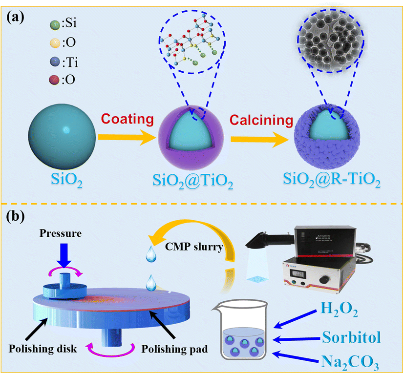 | ||
| Fig. 1 The diagram of the polishing process. | ||
3.2. The structural characteristics of SiO2@TiO2 abrasive particles
SEM was utilized to observe the morphology of mixed commercial SiO2 and TiO2 abrasives, as depicted in Fig. 2(a) and (b). They reveal several drawbacks including non-uniform particle size distribution, a singular spherical morphology, inadequate polishing performance, and a tendency to agglomerate when mixed. These characteristics pose challenges for conducting further experiments on modifying abrasive particles and investigating the mechanisms of abrasive action. After the rough polishing, the surfaces of the quartz glasses were characterized using an optical microscope and a 3D optical surface profiler, as illustrated in Fig. 2(c) and (d). The surface roughness was measured to be 1.008 nm. The 3D surface profilometer image reveals that the surface of the quartz glass is rough and exhibits numerous scratches and protrusions after rough polishing.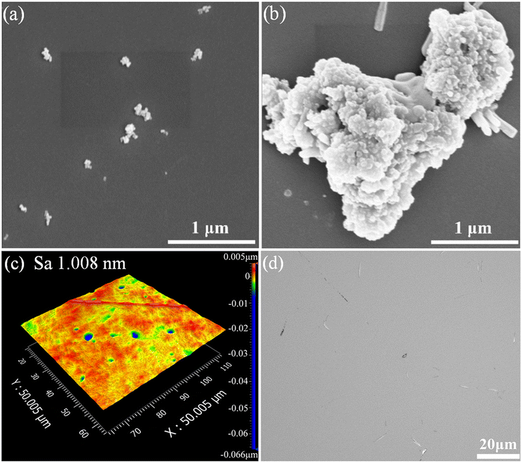 | ||
| Fig. 2 SEM patterns of the abrasives: (a) commercial SiO2; (b) TiO2; (c) the 3D surface profilometer image and (d) optical microscope photo of quartz glasses polished with commercial SiO2 abrasive particles. | ||
SEM, TEM, XRD, and FTIR were employed to analyze the surface appearance, core–shell structure, and the crystal structure of the composite SiO2@TiO2 abrasive particles. Fig. 3 presents the SEM and TEM images and diameter distribution plots of the SiO2 and SiO2@TiO2 abrasive synthesized by the Stöber method. The SEM images (Fig. 3(a) and (d)) and TEM images (Fig. 3(b) and (e)) depict the surface appearance and internal structure of the SiO2 and SiO2@TiO2 abrasive. Twenty randomly selected particles were measured to determine the diameter distribution, resulting in average diameters of 301 ± 34 nm and 387 ± 16 nm for the SiO2 and SiO2@TiO2 abrasive particles, respectively, as illustrated in Fig. 3(c) and (f). Analysis of the SEM and TEM images and diameter distribution plots reveals that the synthesized SiO2 abrasives reveal a smooth spherical morphology and a uniform particle size distribution, making them well-suited for serving as the core component in the composite SiO2@TiO2 abrasive. Additionally, the TEM images demonstrate the distinctive core–shell structure of the composite SiO2@TiO2 abrasive particles.
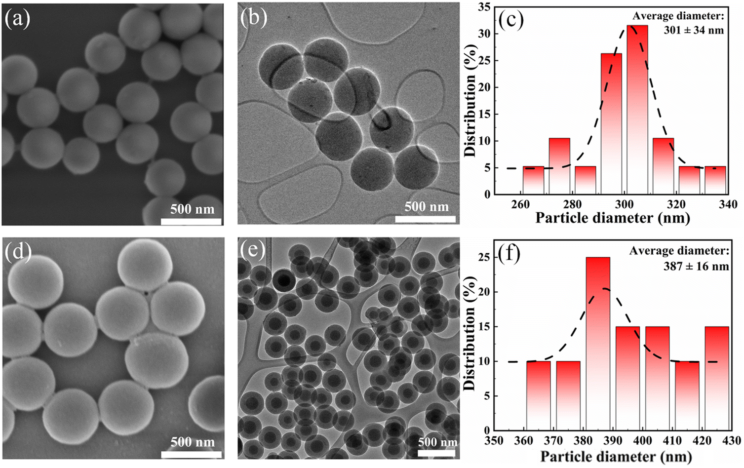 | ||
| Fig. 3 The SEM and TEM images and diameter distributions of the synthesized abrasive particles: (a)–(c) SiO2; (d)–(f) SiO2@TiO2. | ||
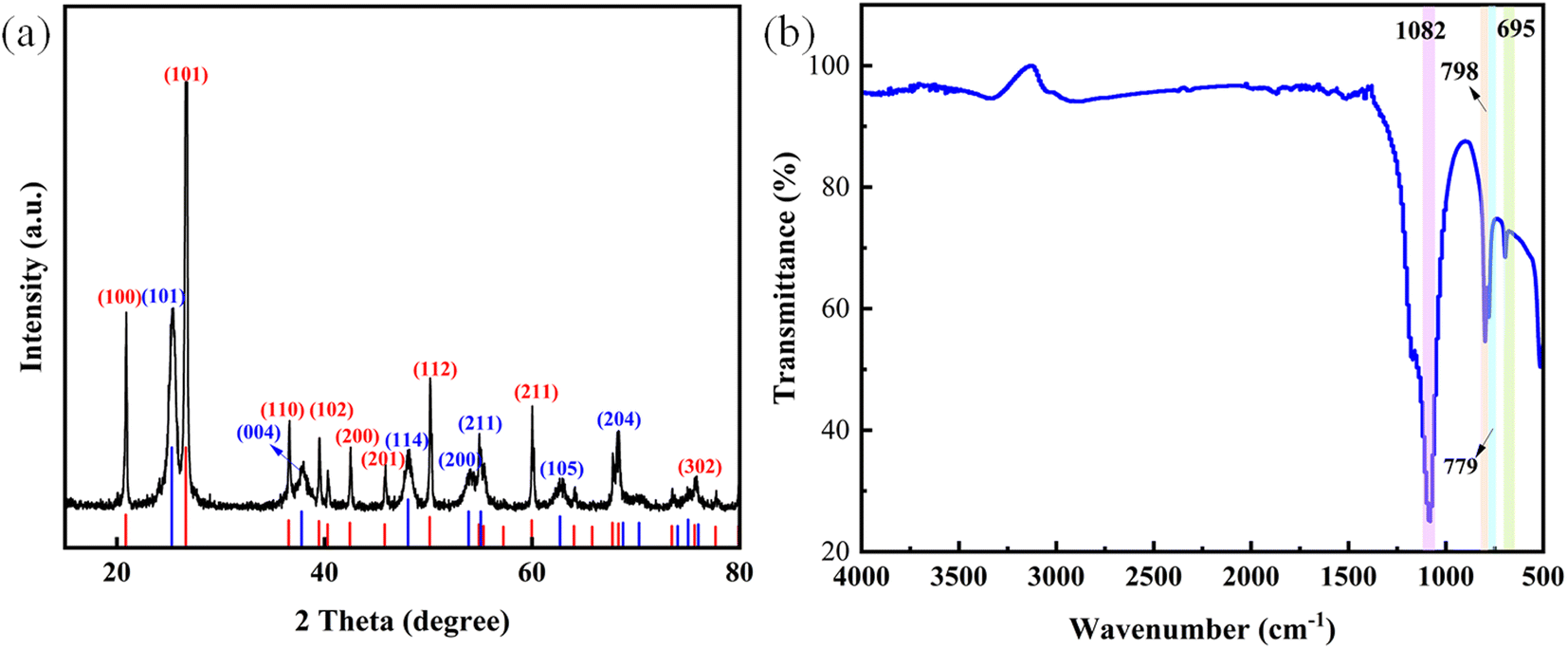
The XRD pattern of the composite SiO2@TiO2 abrasive particles is illustrated in Fig. 4(a). An evident characteristic peak is observed at approximately 23° in the SiO2 spectrum, indicating the high purity of the synthesized SiO2. Furthermore, distinct diffraction peaks are observed in the spectrum at 2θ values of 25.4°, 37.9°, 48°, 54.0°, 62.1°, and 62.7°, corresponding to the crystal planes (101), (004), (200), (105), (211), and (204) of the anatase TiO2 phase, respectively.30 According to the latest literature,31 anatase TiO2 has higher photocatalytic activity than other forms which has been verified. The FTIR image of SiO2@TiO2 is illustrated in Fig. 4(b). SiO2@TiO2 abrasive particles exhibit absorption bands at 1082 cm−1, 798 cm−1, 779 cm−1, and 695 cm−1. The absorption band at 1082 cm−1 primarily corresponds to the vibration of the silicon–oxygen (Si–O) bond, while the absorption band at 798 cm−1 represents the bending vibration of the Si–O bond. The absorption bands at 779 cm−1 and 695 cm−1 are associated with the vibration of the titanium–oxygen (Ti–O) bond. The XRD and FTIR characterization studies demonstrate the high purity of the composite SiO2@TiO2 abrasive particles.
 | ||
| Fig. 4 The XRD and FTIR patterns of SiO2@TiO2: (a) the XRD pattern; (b) the FTIR pattern. | ||
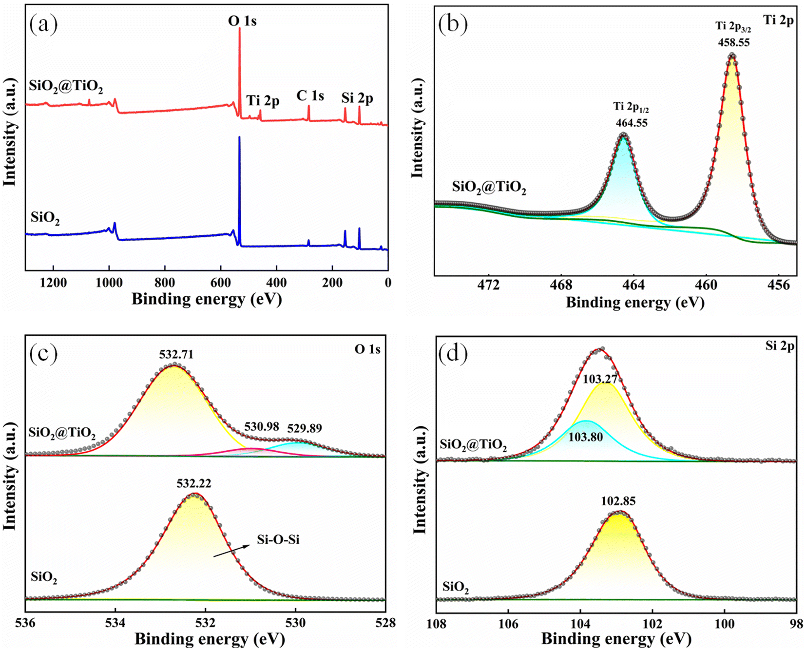
The XPS full-spectrum and fine-spectrum images of SiO2 and SiO2@TiO2 composite particles are shown in Fig. 5. In the full-spectrum scan, characteristic peaks of SiO2 can be observed. The peaks at 533 eV, 285 eV, and 103 eV correspond to O 1s, C 1s, and Si 2p, respectively, as shown in Fig. 5(a). As for the SiO2@TiO2 composite particles, the peaks at 532 eV and 284 eV correspond to O 1s and C 1s,32 while the peaks at 458 eV and 103 eV correspond to Ti 2p and Si 2p.33Fig. 5(b)–(d) depict the high-resolution scans of the Ti, Si, and O elements, respectively. In Fig. 5(b), the Ti 2p spectrum of SiO2@TiO2 reveals two peaks at binding energies of 458.55 eV and 464.55 eV, corresponding to the Ti 2p3/2 and Ti 2p1/2 of Ti atoms in TiO2, respectively. In Fig. 5(c), the high-resolution scan of the O element in SiO2 demonstrates that the O 1s peak is located at 532.33 eV. The high-resolution scan of the O element in SiO2@TiO2 exhibits three peaks at 529.89 eV, 530.98 eV, and 532.71 eV, which are assigned to the O atoms in Ti–O–Ti bonds, –OH groups, and Si–O–Si bonds in SiO2, respectively.34 Additionally, as shown in Fig. 5(c), the O 1s peak in the SiO2–TiO2 spectrum is slightly shifted to 530.98 eV, compared to 532.22 eV of SiO2. This shift may happen because of the difference in the chemical environment which was produced by the bonding of surface hydroxyl groups. In Fig. 5(d), the high-resolution scan of the Si element in SiO2 reveals that the main peak of Si 2p is located at 102.85 eV. Furthermore, the Si 2p spectrum of SiO2@TiO2 exhibits two peaks at binding energies of 103.27 eV and 103.80 eV, corresponding to the Si 2p3/2 and Si 2p1/2 of Si atoms in SiO2, respectively. The peak at 103.27 eV represents the Si atom in the Si–O–Ti bond.35 These results indicate a strong bond between SiO2 and TiO2, supporting the successful preparation of a large amount of composite abrasive SiO2@TiO2 for precision polishing in the experiment.
 | ||
| Fig. 5 The XPS full-spectrum and fine-spectrum images of abrasive particles: (a) the XPS full-spectrum images of SiO2 and SiO2@TiO2; (b)–(d) the Ti, O, and Si elements in fine-spectrum images of SiO2@TiO2. | ||
3.3. Polishing tests
An optical microscope and a 3D optical surface profiler were used to observe the surface of quartz glasses before and after precision polishing. As illustrated in Fig. 6, the surfaces using different ratios of commercial mixed abrasives reflected different surface qualities. Fig. 6(a) reveals that when only commercial TiO2 was used as the abrasive, the quartz glass samples exhibited a higher number of pits. This can be attributed to the dual role of TiO2 as a grinding agent and photocatalyst, leading to chemical reactions during the polishing process. Furthermore, the relatively soft TiO2 abrasive makes it challenging to timely remove the reaction layer, which may result in embedding and the formation of surface pits. As depicted in Fig. 6(b)–(e), with the proportion of abrasives for SiO2 increases, the number of pits caused by titanium dioxide decreases, but the number of scratches increases. This phenomenon can be attributed to the non-uniform size of commercial colloidal silica, which contains numerous small particles that readily adhere to the surface of quartz glass, resulting in the embedding of abrasives and the formation of deep pits, consequently leading to scratches under high-speed relative motion.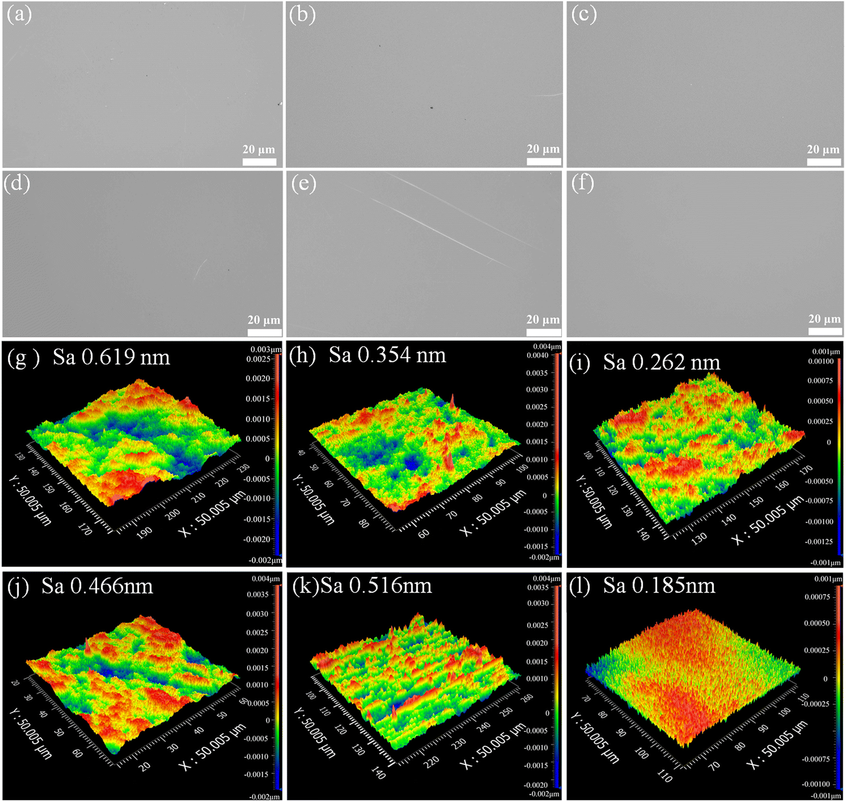 | ||
| Fig. 6 The optical microscope photos and 3D surface profilometer image of quartz glasses polished using different abrasives: the commercial SiO2 and TiO2 abrasives with a ratio of 0:1 (a) and (g); the commercial SiO2 and TiO2 abrasives with a ratio of 1:1 (b) and (h); the commercial SiO2 and TiO2 abrasives with a ratio of 3:2 (c) and (i); the commercial SiO2 and TiO2 abrasives with a ratio of 4:1 (d) and (j); the commercial SiO2 and TiO2 abrasives with a ratio of 1:0 (e) and (k); the SiO2@TiO2 abrasive grains (f) and (l). | ||
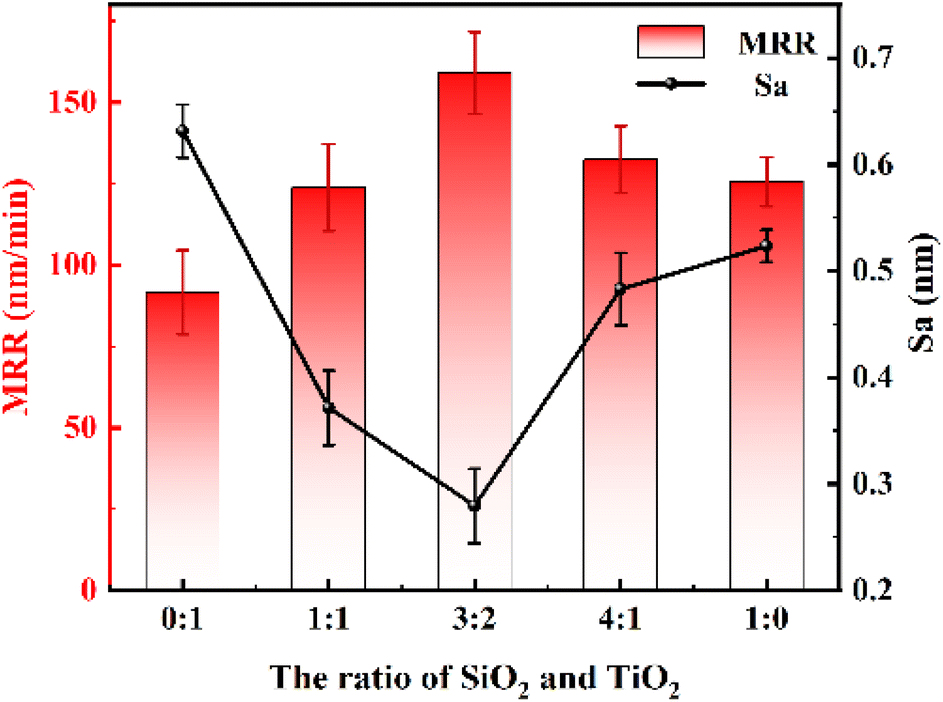
The 3D surface profilometer image of the polished surfaces is presented in Fig. 6(g)–(l). To objectively assess the surface quality of quartz glasses after the precision polishing process under photocatalytic conditions, the surface roughness Sa was measured by randomly selecting 5 points on the sample surface within a 50 μm × 50 μm scanning range. The average roughness values of the samples processed with mixed abrasives were 0.632 ± 0.025 nm, 0.372 ± 0.035 nm, 0.279 ± 0.035 nm, 0.483 ± 0.034 nm, and 0.524 ± 0.015 nm, respectively. Additionally, the average MRR values of the five sample groups were 91.617 ± 12.910 nm min−1, 123.839 ± 13.333 nm min−1, 159.091 ± 12.606 nm min−1, 132.424 ± 10.303 nm min−1, and 125.607 ± 7.576 nm min−1, respectively. It can be observed that the polishing effect is the best and the polishing efficiency is the highest when the mixing ratio of commercial SiO2 (300 nm) and TiO2 (100 nm) is 3:2. Fig. 7 shows the Ra and MRR of the quartz glasses polished with mixed commercial abrasives.
 | ||
| Fig. 7 The Ra and MRR of the quartz glasses polished with mixed commercial abrasives. | ||
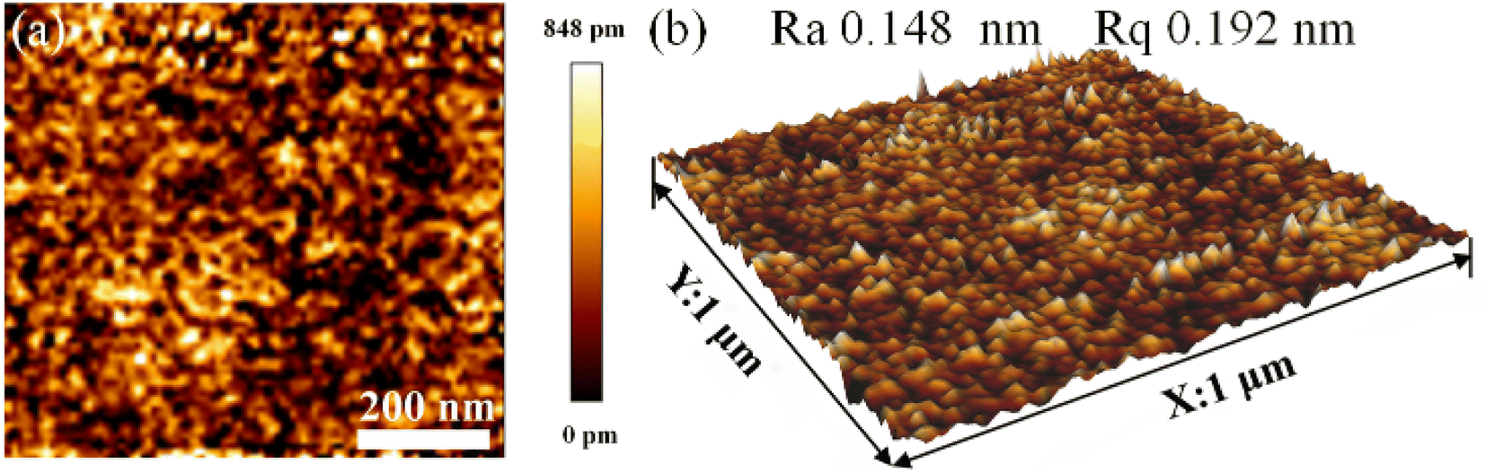
An optical microscope, a 3D optical surface profiler and an AFM were used to observe the surface of quartz glasses after the precision polishing process used the core–shell SiO2@TiO2 abrasives. The 3D surface profilometer image of the polished surface is shown in Fig. 6(l). Within a scanning range of 50 μm × 50 μm, five random points on the sample surface were selected to measure the Sa, which achieved a minimum value of 0.185 nm, indicating the smoothest and most uniform surface. Furthermore, the average MRR of the samples was 144.639 ± 17.445 nm min−1. The surface morphology after polishing is depicted in Fig. 6(f), demonstrating a smooth quartz glass surface without scratches or pits. Fig. 8(a) and (b) present the 2D and 3D morphological images of the AFM measurements on the surface of quartz glass polished with SiO2@TiO2 composite abrasives within a scanning range of 1 × 1 μm2. The obtained Ra value was 0.148 nm and Rq value was 0.192 nm. What's more, the Rq represents the root mean square average of the longitudinal coordinates of the roughness profile. It can be observed that the surface roughness is the lowest when using the composite SiO2@TiO2 abrasives, but the MRR is slightly lower compared to the MRR of the commercially mixed abrasives with a ratio of 3:2. This indicates that the synthesized core–shell SiO2@TiO2 abrasive particles exhibit superior surface flatness processing performance compared to the commercially mixed abrasives. Moreover, the core–shell SiO2@TiO2 abrasive particles offer the highest polishing accuracy and show great potential in the field of ultra-precision manufacturing.
 | ||
| Fig. 8 AFM 2D and 3D morphology patterns of the quartz glass surface after precision polishing using SiO2@TiO2 composite abrasive grains. | ||
The differences in mechanical friction behavior among single-abrasives, mixed-abrasives, and composite core–shell abrasives can be explained from a physical perspective by considering variations in hardness. The quartz glass is composed of 99.9% SiO2.36 In the case of single-abrasives, TiO2 exhibits a relatively low hardness of 6–6.5 when used for abrasives. Consequently, TiO2 is unable to rapidly remove the reaction layer, resulting in relatively poor mechanical polishing efficiency. During the polishing process, TiO2 may become embedded in the reaction layer, resulting in the formation of numerous surface pits. SiO2 possess a higher hardness of 7 compared to TiO2, thereby exhibiting stronger mechanical removal capabilities. SiO2 abrasives can effectively remove the reaction layer and promote chemical reactions on the newly exposed surface. When SiO2 and TiO2 are mixed in different proportions as abrasive particles for polishing, under photocatalytic conditions, the combined use of these two abrasives can yield a smoother surface that surpasses the performance achievable with single-grain abrasives alone.
When two different types of abrasive particles are combined, their roles in the polishing process undergo a transformation. SiO2@TiO2 composite abrasive particles, which are a physical combination of two types of abrasive particles, exhibit distinct functionality during the polishing process. According to ref. 37, the quartz glass undergoes hydrolysis to generate ˙OH radicals, which react with the surface to form silanol groups. Under photocatalytic conditions, the outer shell of nano-sized TiO2 acts as a highly active catalyst, demonstrating the highest catalytic activity on fused quartz substrates.38 When TiO2 is used as a catalyst, based on the band theory, photoexcited electron–hole pairs and the corresponding photocatalytic reduction reactions occur when the energy of the incident photons equals or exceeds the band gap. This leads to the excitation of TiO2 from the valence band to the conduction band, resulting in the generation of free electrons.39,40 Simultaneously, positively charged holes are formed in the valence band, leading to the generation of more ˙OH radicals,36 as shown in eqn (2) and (3).
| TiO2 + hν → h+ + e− | (2) |
| H2O + h+ → ˙OH + H2 | (3) |
Hydroxylation under alkaline conditions forms the basis for enhancing the surface quality of quartz glass. Meanwhile, H2O2 in the polishing solution can promote the dehydroxylation reaction of silanol structures,41,42 further oxidizing ![[triple bond, length as m-dash]](https://www.rsc.org/images/entities/char_e002.gif) Si–OH to form Si–O–Si bonds. Furthermore, the positively charged holes generated in the valence band of TiO2 can undergo oxidation reactions with H2O2 molecules and hydroxide ions (OH−) adsorbed on the surface of catalyst particles in the polishing solution, resulting in the production of more hydroxyl radicals ˙OH with strong oxidative properties. The generated ˙OH radicals react with the surface of quartz glass, leading to the formation of additional silanol structures. This process can be represented by using eqn (4) and (5). Under photocatalytic conditions, and based on eqn (2) and (5), it can be inferred that TiO2, acting as a catalyst, enhances the chemical hydroxylation reaction, thereby resulting in the formation of a thicker reaction layer on the sample.
Si–OH to form Si–O–Si bonds. Furthermore, the positively charged holes generated in the valence band of TiO2 can undergo oxidation reactions with H2O2 molecules and hydroxide ions (OH−) adsorbed on the surface of catalyst particles in the polishing solution, resulting in the production of more hydroxyl radicals ˙OH with strong oxidative properties. The generated ˙OH radicals react with the surface of quartz glass, leading to the formation of additional silanol structures. This process can be represented by using eqn (4) and (5). Under photocatalytic conditions, and based on eqn (2) and (5), it can be inferred that TiO2, acting as a catalyst, enhances the chemical hydroxylation reaction, thereby resulting in the formation of a thicker reaction layer on the sample.
| H2O2 + hν + OH− → ˙OH + H2O | (4) |
| ˙OH + SiO2 + H2O → Si(OH)40 | (5) |
To investigate the removal mechanism of SiO2@TiO2 composite abrasive particles, XPS full-spectrum scans and Raman spectra were obtained for quartz glass samples soaked in the polishing solution for 7 days and subjected to precision polishing, as shown in the Fig. 9. The Raman spectra were recorded and are presented in Fig. 9(b). The quartz glass surfaces before and after polishing exhibited clear absorption peaks at 460 cm−1, 605 cm−1,36 794 cm−1, and 1050 cm−1. Among them, the band at 460 cm−1 corresponds to the bending vibration peak of the silicon–oxygen bond, while the bands at 605 cm−1 and 1070 cm−1 correspond to the stretching vibration peaks of the silicon–oxygen bond. The band at 794 cm−1 corresponds to the rotational vibration peak of the silicon-oxygen tetrahedron. Additionally, the surface of the quartz glass sample soaked in the polishing solution for 7 days exhibited a notable absorption peak at 2950 cm−1, corresponding to the stretching vibration peak of the O–H group.
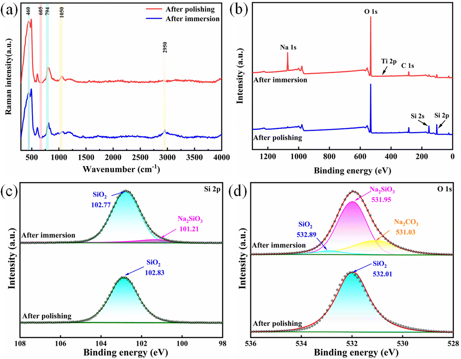 | ||
| Fig. 9 The Raman spectra of the quartz glass samples before and after precision polishing (a); XPS full-spectrum scans of the quartz glass samples before and after precision polishing (b); XPS high-resolution survey spectra of Si 2p and O 1s on the silicon glass surfaces before and after precision polishing (c) and (d). | ||
The XPS full-spectrum scans of the quartz glass samples, which were soaked in the polishing solution for 7 days and then subjected to precision polishing, have been recorded and are presented in Fig. 9(c) and (d). Following a 7-day immersion in the polishing solution, the surface of the quartz glass sample displays a prominent peak at 1071 eV in Na 1s,32 along with main peaks at 532 eV and 284 eV, corresponding to O 1s and C 1s, respectively. The main peak at 458 eV corresponds to Ti 2p, with a lower peak value, signifying that TiO2 plays a role in polishing as both a catalyst and an abrasive, without involvement in other chemical reactions that result in new substances. After precision polishing, the main peak corresponding to Na 1s nearly disappeared, suggesting the successful removal of the sodium-containing substance that had formed on the surface of the quartz glass due to the presence of SiO2@TiO2 composite abrasives during soaking in the polishing solution. In the XPS full-spectrum scan of the quartz glass sample after fine polishing, the main peaks at 154 eV and 103 eV correspond to Si 2s and Si 2p, respectively. It is known that SiO2 is susceptible to corrosion under alkaline conditions, resulting in the formation of soluble SiO32− ions.43 After precision polishing, there is a notable increase in the Si content on the surface of the silica sample. The Si 1s XPS spectra of quartz glass samples, both before immersion in the polishing slurry and after precision polishing, are presented in Fig. 9(c). In the polished quartz glass sample, the peaks at 102.77 eV and 101.21 eV were identified as corresponding to SiO2 and Na2SiO3, respectively. However, after the polishing process, only a single main peak at 102.83 eV, attributed to Si from SiO2, was observed in the fitted curve. The O 1s XPS spectra of quartz glass, both before immersion in the polishing slurry and after polishing, are presented in Fig. 9(d). The peaks at 531.03 eV, 531.95 eV, and 532.89 eV, observed in the XPS spectra of quartz glass immersed in the polishing slurry, are likely associated with Na2CO3, Na2SiO3, and SiO2, respectively.28 After polishing, only a single main peak at 532.01 eV, attributed to SiO2, was observed in the fitted XPS curve. This observation suggests the successful removal of Na2CO3 and Na2SiO3 species that were generated on the surface of quartz glass after immersion in the polishing slurry.19 Based on the XPS analysis, we can infer that the following reaction occurs during the PCMP process,19,32 leading to the oxidation of Si–OH to Si–O–Si:
| Na2CO3 + H2O → 2Na+ + HCO3− + CO2 | (6) |
| HCO3− + H2O → H2CO3 + OH− | (7) |
| SiO2 + OH− → (SiO3)2− + H2O | (8) |
To demonstrate the environmentally friendly nature of the polishing solution, FTIR characterization was performed on the polished quartz glass samples, as illustrated in Fig. 10. The polished quartz glass surface exhibited absorption bands at 1140 cm−1, 970 cm−1, and 775 cm−1. The bands observed at 1140 cm−1 and 970 cm−1 correspond to the asymmetric stretching vibrations of silicon–oxygen bonds, while the band at 970 cm−1 corresponds to the asymmetric bending vibration of silicon–oxygen bonds. The characterization results indicate the absence of impurities on the surface of the polished quartz glass after polishing, demonstrating the feasibility of visible light-assisted catalytic chemical mechanical polishing in the field of ultra-precision machining.
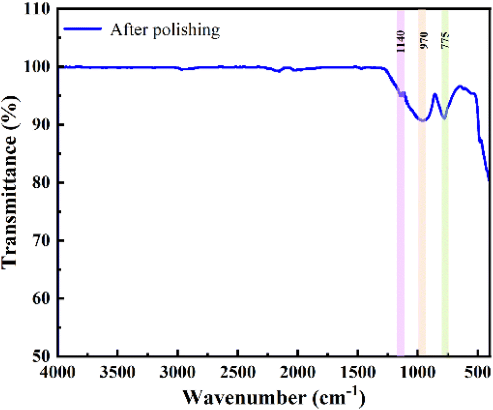 | ||
| Fig. 10 The FTIR spectra of the quartz glass sample after precision polishing. | ||
Based on the aforementioned analysis, a material removal mechanism for polishing quartz glass under photocatalytic conditions using SiO2@TiO2 composite abrasives is proposed, as illustrated in Fig. 11. Initially, driven by external load and kinetic energy, the SiO2@TiO2 abrasives exhibit rapid motion and experience fast friction with the quartz glass surface, leading to impact-induced protrusion collapse and generation of frictional heat. This mechanical effect accelerates the molecular movement of chemical components in the polishing solution, initiating a series of chemical reactions. First, the original fused quartz glass surface reacts with the aqueous solution to form silanol. Subsequently, the silanol reacts with OH− generated in the alkaline environment provided by the Na2CO3 aqueous solution, resulting in the formation of SiO32−. Simultaneously, under the photocatalytic conditions, the TiO2 shell of the SiO2@TiO2 composite abrasives is excited by using a xenon lamp light source, leading to the generation of additional hydroxyl radicals on the fused quartz glass surface, thereby accelerating the reaction rate and forming a thicker chemical reaction layer. Moreover, H2O2 facilitates the dehydrogenation reaction of silanol, further generating Si–O–Si. During the PCMP process, the reaction-generated silicates undergo elastic deformation due to the well-ordered structure of SiO2@TiO2 nanocomposite abrasives, and they are precisely removed under the compression of the polishing pad and quartz glass. Finally, the resultants are discharged along with the flowing polishing solution. After several iterations of this PCMP cycle, the surface precision of the quartz glass eventually reaches the sub-nanometer level.
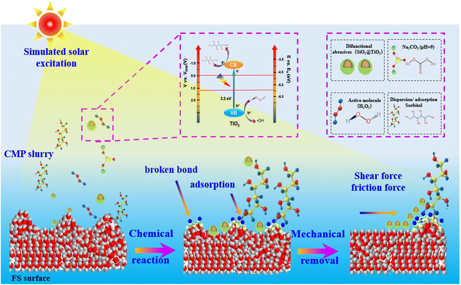 | ||
| Fig. 11 The material removal mechanism for polishing quartz glasses using SiO2@TiO2 composite abrasives under photocatalytic conditions. | ||
4. Conclusion
This study introduces a novel green and environmentally friendly PCMP polishing solution consisting of H2O2, Na2CO3, and DI·H2O. Additionally, bulk-synthesized SiO2@TiO2 core–shell structure abrasives, with diameters ranging from 350 to 400 nm, were employed. The implementation of the PCMP process yields the achievement of an exceptionally smooth and high-quality surface on fused silica, with a surface roughness Sa = 0.185 nm. In comparison to the samples subjected to the commercial CMP that utilized a mixture of TiO2 and SiO2 abrasive particles, the surface roughness demonstrates a reduction of 29%. Elucidation of the mechanistic underpinnings of PCMP is provided based on findings from XPS and Raman spectroscopy. The process is initiated with the reaction of the quartz glass surface with the aqueous solution to form the silanol groups. Subsequently, the silanol groups react with OH− ions sourced from the Na2CO3 aqueous solution, generating SiO32− species in an alkaline environment. Simultaneously, under the photocatalytic conditions, the TiO2 shell of SiO2@TiO2 composite abrasive particles is excited by using a xenon lamp source, leading to the increased production of hydroxyl radicals on the quartz glass surface. This result contributes to the formation of a thicker chemical reaction layer. Additionally, H2O2 also promotes the dehydrogenation reaction of silanol, further producingSi–O–Si bonds accelerating the reaction rate. During the PCMP process, the generated silicates are effectively removed by SiO2@TiO2 abrasives, resulting in the remarkably smooth quartz glass surface.
Data availability
The authors are unable or have chosen not to specify which data have been used.Author contributions
Yuanhang Fan: investigation, formal analysis, data curation. Zhenyu Zhang: funding acquisition, visualization, project administration, conceptualization, supervision. Jiaxin Yu: investigation, formal analysis, data curation. Xingqiao Deng: investigation, formal analysis. Chunjing Shi: formal analysis, data curation.Conflicts of interest
The authors declare that they have no known competing financial interests or personal relationships that could have appeared to influence the work reported in this paper.Acknowledgements
The authors acknowledge the financial support from the National Key Research and Development Program of China (2018YFA0703400), the Young Scientists Fund of the National Natural Science Foundation of China (52205447), the Changjiang Scholars Program of the Chinese Ministry of Education, and the Xinghai Science Funds for Distinguished Young Scholars.References
- X. Guo, S. Yuan, J. Huang, C. Chen, R. Kang, Z. Jin and D. Guo, Appl. Surf. Sci., 2020, 505, 144610 CrossRef CAS.
- G. Ren, H. Song, J. Dan, J. Li, P. Pan, Z. Yang, J. Xiao and J. Xu, Int. J. Heat Mass Transfer, 2020, 148, 119078 CrossRef CAS.
- M. Mader, O. Schlatter, B. Heck, A. Warmbold, A. Dorn, H. Zappe, P. Risch, D. Helmer, F. Kotz and B. E. Rapp, Science, 2021, 372, 182–186 CrossRef CAS PubMed.
- F. Kotz, K. Arnold, W. Bauer, D. Schild, N. Keller, K. Sachsenheimer, T. M. Nargang, C. Richter, D. Helmer and B. E. Rapp, Nature, 2017, 544, 337–339 CrossRef CAS PubMed.
- T. Sumitomo, H. Huang and L. Zhou, International Journal of Machine Tools and Manufacture, 2011, 51, 182–189 CrossRef.
- G. M. Whitesides, Nature, 2006, 442, 368–373 CrossRef CAS PubMed.
- W. Peng, X. Deng, Z. Luo and S. Li, Optik, 2018, 171, 71–76 CrossRef CAS.
- H. Yumoto, H. Mimura, T. Koyama, S. Matsuyama, K. Tono, T. Togashi, Y. Inubushi, T. Sato, T. Tanaka and T. Kimura, Nat. Photonics, 2013, 7, 43–47 CrossRef CAS.
- I. Hervas, A. Montagne, A. Van Gorp, M. Bentoumi, A. Thuault and A. Iost, Ceram. Int., 2016, 42, 12740–12750 CrossRef CAS.
- S. Qiao, F. Shi, X. Shen and J. Song, J. Manuf. Process., 2022, 77, 831–837 CrossRef.
- X. Guo, J. Huang, S. Yuan, C. Chen, Z. Jin, R. Kang and D. Guo, Appl. Surf. Sci., 2020, 501, 144170 CrossRef CAS.
- M. Krishnan, J. W. Nalaskowski and L. M. Cook, Chem. Rev., 2010, 110, 178–204 CrossRef CAS.
- X. Shi, G. Pan, Y. Zhou, C. Zou and H. Gong, Appl. Surf. Sci., 2013, 284, 195–206 CrossRef CAS.
- X. Cui, Z. Zhang, C. Shi, F. Meng, G. Xu, W. Xie, Z. Liu, J. Wang and W. Wen, Materials Today Sustainability, 2022, 20, 100257 CrossRef.
- K. Wakamatsu, S. Kurokawa, T. Toyama and T. Hayashi, Precis. Eng., 2019, 60, 458–464 CrossRef.
- B. Duan, J. Zhou, Y. Liu, M. Sun and Y. Zhang, J. Semicond., 2014, 35, 116001 CrossRef.
- H. M. Kim, R. P. Venkatesh, T. Y. Kwon and J. G. Park, Colloids Surf., A, 2012, 411, 122–128 CrossRef CAS.
- Y. Li, Z. Zhang, C. Shi, D. Liu and L. Liu, Colloids Surf., A, 2023, 662, 131000 CrossRef CAS.
- Z. Zhao, Z. Zhang, C. Shi, J. Feng, X. Zhuang, L. Li, F. Meng, H. Li, Z. Xue and D. Liu, Materials, 2023, 16, 1148 CrossRef CAS PubMed.
- G. S. Pan, Z. H. Gu, Y. Zhou, T. Li, H. Gong and Y. Liu, Wear, 2011, 273, 100–104 CrossRef CAS.
- P. Gao, T. Liu, Z. Zhang, F. Meng, R. Ye and J. Liu, Sci. China Mater., 2021, 64, 2747–2763 CrossRef CAS.
- J. Wang, T. Wang, G. Pan and X. Lu, Appl. Surf. Sci., 2016, 361, 18–24 CrossRef CAS.
- J. Wang, T. Wang, G. Pan and X. Lu, Appl. Surf. Sci., 2016, 378, 130–135 CrossRef CAS.
- X. Yu, B. Zhang, R. Wang, Z. Kao and S. Yang, Mater. Sci. Semicond. Process., 2021, 121, 105387 CrossRef CAS.
- W. Wang, B. Zhang, Y. Shi, T. Ma, J. Zhou and R. Wang, J. Mater. Process. Technol., 2021, 295, 1 Search PubMed.
- J. Liu, Z. Zhang, C. Shi, Z. Ren, J. Feng, H. Zhou, Z. Liu, F. Meng and S. Zhao, Appl. Surf. Sci., 2023, 637, 157978 CrossRef CAS.
- Y. Chen, L. Zhong, A. Chen, M. Fu and X. Lu, Ceram. Int., 2023, 49, 16932–16943 CrossRef CAS.
- Y. Li, Z. Zhang, C. Shi, D. Liu and L. Liu, Precis. Eng., 2017, 49, 235–242 CrossRef.
- A. Chen, T. Wang, Y. Chen, S. Wang and Y. Chen, Appl. Surf. Sci., 2022, 575, 151784 CrossRef CAS.
- X. Wang, H. Ding, G. Lv, R. Zhou, R. Ma, X. Hou, J. Zhang and W. Li, Ceram. Int., 2022, 48, 20033–20040 CrossRef CAS.
- S. R. Damkale, S. S. Arbuj, G. G. Umarji, S. B. Rane and B. B. Kale, RSC Adv., 2021, 11, 7587–7599 RSC.
- G. Xu, Z. Zhang, F. Meng, L. Liu, D. Liu, C. Shi, X. Cui, J. Wang and W. Wen, J. Manuf. Process., 2023, 85, 783–792 CrossRef.
- K. P. O. Mahesh, D. H. Kuo and B. R. Huang, J. Mol. Catal. A: Chem., 2015, 396, 290–296 CrossRef CAS.
- J. Zhong, J. Li, F. Feng, Y. Lu, J. Zeng, W. Hu and Z. Tang, J. Mol. Catal. A: Chem., 2012, 357, 101–105 CrossRef CAS.
- S. Ullah, E. P. Ferreira-Neto, A. A. Pasa, C. C. J. Alcantara, J. J. S. Acuna, S. A. Bilmes, M. L. M. Ricci, R. Landers, T. Z. Fermino and U. P. Rodrigues, Appl. Catal., B, 2015, 179, 333–343 CrossRef CAS.
- S. Petitgirard, C. J. Sahle, W. J. Malfait, G. Spiekermann, I. Blanchard, E. S. Jennings, M. Cotte and M. Murakami, Phys. Rev. B, 2022, 105, 134106 CrossRef CAS.
- L. M. Cook, J. Non-Cryst. Solids, 1990, 120, 152–171 CrossRef CAS.
- A. Fernandez, G. Lassaletta, V. M. Jimenez, A. Justo, A. R. GonzalezElipe, J. M. Herrmann, H. Tahiri and Y. AitIchou, Appl. Catal., B, 1995, 7, 49–63 CrossRef CAS.
- X. Kang, S. Liu, Z. Dai, Y. He, X. Song and Z. Tan, Catalysts, 2019, 9, 191 CrossRef.
- M. A. Henderson, Surf. Sci. Rep., 2011, 66, 185–297 CrossRef CAS.
- T. Bakos, S. N. Rashkeev and S. T. Pantelides, Phys. Rev. Lett., 2002, 88, 05508 CrossRef.
- X. Guo, J. Huang, S. Yuan, R. Kang and D. Guo, Appl. Surf. Sci., 2021, 556, 149556 Search PubMed.
- Q. Shao, S. Duan, L. Fu, B. Lyu, P. Zhao and J. Yuan, Micromachines, 2021, 12, 956 CrossRef PubMed.
| This journal is © The Royal Society of Chemistry 2024 |