 Open Access Article
Hollow Ru/RuO2 nanospheres with nanoparticulate shells for high performance electrocatalytic oxygen evolution reactions†
Kyoungil
Cho‡
 a,
June Young
Jang‡
a,
Yoon-Joo
Ko
b,
Yoon
Myung
*c and
Seung Uk
Son
a,
June Young
Jang‡
a,
Yoon-Joo
Ko
b,
Yoon
Myung
*c and
Seung Uk
Son
 *a
*a
aDepartment of Chemistry, Sungkyunkwan University, Suwon 16419, Korea. E-mail: sson@skku.edu
bLaboratory of Nuclear Magnetic Resonance, National Center for Inter University Research Facilities (NCIRF), Seoul National University, Seoul 08826, Korea
cKorea Institute of Industrial Technology, Advanced Energy Materials and Components R&D Group, Busan 46744, Korea. E-mail: myungyoon@kitech.re.kr
First published on 15th December 2023
Abstract
This work shows that hollow Ru/RuO2 nanoparticles having nanoparticulate shells (HN-Ru/RuO2) can be prepared using hollow microporous organic polymers with Ru species (H-MOP-Ru) as precursors. Using silica spheres as templates, H-MOPs were prepared through the Sonogashira–Hagihara coupling of 1,3,5-triethynylbenzene with 2,3-ethoxymethylenedioxy-1,4-diiodobenzene. Acid hydrolysis of cyclic ethyl orthoformate protecting groups generated catechol moieties to form H-MOP-Cat. Then, H-MOP-Ru was obtained by incorporating Ru species into H-MOP-Cat. Heat-treatment of H-MOP-Ru under air induced the formation of HN-Ru/RuO2 with a diameter of 61 nm and shells consisting of 6–7 nm nanoparticles. Due to the hollow structure and nanoparticulate shells, HN-Ru/RuO2 showed a high surface area of 80 m2 g−1 and a pore volume of 0.18 cm3 g−1. The HN-Ru/RuO2 showed enhanced electrocatalytic performance for the oxygen evolution reaction (OER) with an overpotential of 295 mV @ 10 mA cm−2 and a Tafel slope of 46 mV dec−1 in alkaline electrolyte, compared with control RuO2 such as commercial Ru/RuO2 nanoparticles (A-Ru/RuO2) and home-made Ru/RuO2 nanoparticles (N-Ru/RuO2) prepared via the same synthetic procedure as HN-Ru/RuO2. While HN-Ru/RuO2 inevitably contained Pd originated from coupling catalysts, it showed superior performance to Ru/RuO2 nanoparticles with the same Pd content (N1-Ru/RuO2), indicating that the efficient electrocatalytic performance of HN-Ru/RuO2 is attributable to its hollow structure and nanoparticulate shells.
Introduction
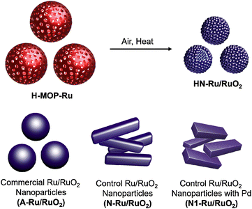
As climate change is becoming a more and more critical issue in our society, carbon neutralization-related technologies are attracting great attention from scientists.1 Hydrogen has been considered as an alternative energy source of carbon-based fossil fuels.2 To realize the hydrogen economy, the production, storage, and utilization technologies of hydrogen require continuous advances.2 For hydrogen production, electrocatalytic water splitting has been regarded as one of the most promising methods.3 To realize electrocatalytic full water splitting, efficient electrocatalysts for both the cathodic hydrogen evolution reaction (HER) and anodic oxygen evolution reaction (OER) are required.3 While significant progress has been made in the development of HER electrocatalysts, OER electrocatalysts require more exploration.4Ru/RuO2 has been studied as a representative electrocatalyst for the OER.5 However, the OER process catalyzed by Ru/RuO2 is relatively slow. Morphology engineering of Ru/RuO2 can improve its catalytic performance (Fig. 1).6,7
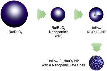 | ||
| Fig. 1 Morphology engineering of Ru/RuO2 electrocatalysts to nanoparticles, hollow nanoparticles, and hollow nanoparticles with nanoparticulate shells. | ||
For example, nanosized Ru/RuO2 particles showing improved electrocatalytic OER performance, due to enhanced surface area and efficient utilization of catalytic sites, have been prepared.6–8 Recently, it has been reported that a hollow structure can enhance the catalytic performance of nano-sized catalysts, due to efficient mass transfer of substrates and high surface areas.9 Moreover, hollow Ru/RuO2 nanoparticles with nanoparticulate shells (HN-Ru/RuO2) can be a promising candidate for development of efficient electrocatalysts for the OER. However, the synthetic route to the HN-Ru/RuO2 is limited, thus requiring further exploration.10
Recently, microporous organic polymers (MOPs) have been prepared by various coupling reactions of organic building blocks.11–15 Moreover, using anchoring groups, metals can be incorporated into MOPs.16–26 Our research group has reported morphology-engineered synthesis of MOPs.27 Especially, hollow MOPs (H-MOPs) have been prepared using silica and metal organic framework particles as templates.28,29 The H-MOPs can be utilized as templates for synthesizing inorganic nanomaterials such as hollow Ru/RuO2 nanomaterials.
In this work, we report the synthesis of hollow MOPs bearing catechol moieties (H-MOP-Cat). Incorporation of Ru species into hollow MOPs and successive calcination under air resulted in the formation of hollow Ru/RuO2 nanoparticles. Especially, the shells of hollow Ru/RuO2 nanoparticles have a nanoparticulate feature. The resultant HN-Ru/RuO2 showed excellent OER performance, better than that of Ru/RuO2 nanomaterials.
Experimental
General information
Scanning electron microscopy (SEM) was conducted using a JSM7100F microscope at the Chiral Material Core Facility Center of Sungkyunkwan University. Transmission electron microscopy (TEM) and high-resolution TEM (HR-TEM) images were obtained using a JSM2100F microscope. Energy dispersive X-ray spectroscopy (EDS) was conducted using TEM equipment. N2 adsorption–desorption isotherm curves were obtained at 77 K using a Micromeritics ASAP2020. The surface areas of materials were measured through analysis of adsorption isotherm curves based on Brunauer–Emmett–Teller (BET) theory. Pore size analysis diagrams were obtained through analysis of N2 adsorption curves based on the non-local density functional theory (NLDFT) method. X-ray photoelectron spectroscopy (XPS) was conducted using a Thermo VG spectrometer. Powder X-ray diffraction (PXRD) studies were conducted using a Rigaku MAX-2200. Infrared (IR) absorption spectroscopy was conducted using a Bruker VERTEX70. Solid state 13C nuclear magnetic resonance spectroscopy (NMR) was conducted in cross polarization (CP)/total sideband suppression (TOSS) mode using a 500 MHz Bruker AVANCE II NMR spectrometer. Solution state 1H NMR spectra were obtained using a Bruker Ascend 500 spectrometer. Thermogravimetric analysis (TGA) was conducted using a TG/DTA 7300. Inductively coupled plasma atomic emission spectroscopy (ICP-AES) analysis was conducted using an OPTIMA 8300.Synthesis of building blocks
To prepare a cyclic ethyl orthoformate-protected 1,4-diiodo-2,3-catechol (2,3-ethoxymethylenedioxy-1,4-diiodobenzene) building block (Fig. 2), 2,3-dihydroxy-1,4-diiodobenzene was synthesized, following the synthetic method reported in the literature.30,31 In this work, the following procedures were applied. 1,2-Dimethoxybenzene (18.5 mL, 0.145 mol), tetramethylethylenediamine (20 mL, 0.13 mol), and distilled hexane (50 mL) were added to a flame-dried 250 mL Schlenk flask under argon. After n-BuLi (1.6 M in hexane, 100 mL, 0.16 mol) was added dropwise for 1 h, the reaction mixture was stirred at room temperature for 28 h. After trimethylsilyl chloride (22.5 mL, 0.177 mol) was added dropwise at −78 °C, the reaction mixture was stirred at room temperature for 5 h. After further stirring at 30 °C for 30 min, the product was extracted using hexane and water. After the hexane solution was dried with MgSO4, the volatile liquid was evaporated. Then 1,2-dimethoxy-3-trimethylsilylbenzene was isolated by flash column chromatography.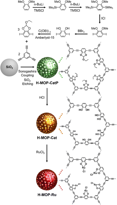 | ||
| Fig. 2 Synthesis of a cyclic ethyl orthoformate (Ceof)-protected 1,4-diiodo-2,3-catechol (2,3-ethoxymethylenedioxy-1,4-diiodobenzene) building block, H-MOP-CatP, H-MOP-Cat, and H-MOP-Ru. | ||
To prepare 2,3-dimethoxy-1,4-bis(trimethylsilyl)benzene, 1,2-dimethoxy-3-trimethylsilylbenzene (30.4 g, 0.145 mol), tetramethylethylenediamine (20 mL, 0.13 mol), and distilled hexane (50 mL) were added to a flame-dried 250 mL Schlenk flask under argon. After n-BuLi (1.6 M in hexane, 100 mL, 0.16 mol) was added dropwise for 1 h, the reaction mixture was stirred at room temperature for 28 h. After trimethylsilyl chloride (22.5 mL, 0.177 mol) was added at −78 °C dropwise, the reaction mixture was stirred at room temperature for 5 h. After the reaction mixture was further stirred at 30 °C for 30 min, the product was extracted using hexane and water. After the hexane solution was dried with MgSO4, the volatile liquid was evaporated. Then 2,3-dimethoxy-1,4-bis(trimethylsilyl)benzene was isolated by flash column chromatography.
To prepare 1,4-diiodo-2,3-dimethoxybenzene, 2,3-dimethoxy-1,4-bis(trimethylsilyl)benzene (31 g, 0.11 mol) and distilled methylene chloride (160 mL) were added to a 500 mL round-bottomed flask. After iodine monochloride (44.6 g, 0.275 mol) dissolved in methylene chloride (160 mL) was added dropwise, the reaction mixture was stirred at room temperature for 30 min. Using an aqueous sodium thiosulfate solution, the product was extracted. After drying the methylene chloride solution with MgSO4, the volatile liquid was evaporated to obtain 1,4-diiodo-2,3-dimethoxybenzene. To prepare 2,3-dihydroxy-1,4-diiodobezene, 1,4-diiodo-2,3-dimethoxybenzene (6.0 g, 17 mmol) and methylene chloride (3 mL) were added to a flame-dried 100 mL Schlenk flask under argon. After cooling to −78 °C, BBr3 (1 M in methylene chloride, 50 mL, 50 mmol) was added dropwise. After its temperature increased to room temperature, the reaction mixture was poured into ice water. The product was extracted using methylene chloride and water. After drying with sodium sulfate, the volatile liquid was evaporated. Then 2,3-dihydroxy-1,4-diiodobezene was purified by flash column chromatography.
To prepare a Ceof-protected 1,4-diiodo-2,3-catechol building block, 2,3-dihydroxy-1,4-diiodobezene (2.4 g, 6.6 mmol) and distilled toluene (65 mL) were added to a flame-dried 250 mL Schlenk flask. After Amberlyst-15 (45 mg) and triethyl orthoformate (3.3 mL, 20 mmol) were added, the reaction mixture was stirred at 140 °C for 18 h. After cooling to room temperature, the volatile liquid was evaporated. After the product was extracted using methylene chloride and water, the methylene chloride solution was dried with MgSO4. After the volatile liquid was evaporated, cyclic ethyl orthoformate-protected 1,4-diiodo-2,3-catechol was isolated by flash column chromatography. The 1H NMR spectrum of the building block, cyclic ethyl orthoformate-protected 1,4-diiodo-2,3-catechol, matched well with that described in the literature.30,31
Synthesis of H-MOP-Ru
To synthesize H-MOP-Ru, H-MOP-CatP (refer to Fig. 2) was prepared as follows. To use as templates, silica spheres with an average diameter of 180 nm were prepared by the Stöber method reported in the literature.32 In this work, the following procedures were applied. Aqueous ammonia solution (25–30%, 5 mL), water (8 mL), and ethanol (200 mL) were added to a 250 mL round-bottomed flask. After stirring at room temperature for 30 min, tetraethyl orthosilicate (TEOS, 14 mL) was added. The reaction mixture was stirred at room temperature for 18 h. After a mixture of methylene chloride (30 mL) and hexane (200 mL) was added to the reaction mixture, silica spheres were isolated by centrifugation, washed with a mixture of methanol (20 mL) and acetone (20 mL) four times, and dried under vacuum.Silica spheres (0.30 g), (PPh3)2PdCl2 (14 mg, 20 μmol), CuI (4.0 mg, 20 μmol), distilled triethylamine (TEA, 40 mL), distilled tetrahydrofuran (THF, 12 mL), and distilled dimethylformamide (DMF, 3 mL) were added to a flame-dried Schlenk flask under argon. After the reaction mixture was sonicated at room temperature for 1 h, the THF solution (5 mL) of 2,3-ethoxymethylenedioxy-1,4-diiodobenzene (0.12 g, 0.30 mmol) and 1,3,5-triethynylbenzene (30 mg, 0.20 mmol) was added at room temperature. The reaction mixture was stirred at 80 °C for 24 h. After cooling to room temperature, SiO2@MOP-CatP was separated by centrifugation, washed with a mixture of methylene chloride (15 mL) and acetone (25 mL) three times and methanol (40 mL) three times, and dried under vacuum. After SiO2@MOP-CatP was added to a 50 mL Falcon tube, a mixture of hydrofluoric acid (48%, 5 mL), THF (10 mL), and water (15 mL) was added. Caution: Since hydrofluoric acid solution is extremely toxic, it should be handed with specific gloves in an effective hood. After stirring at room temperature for 2 h, the H-MOP-CatP was isolated by centrifugation, washed with a mixture of methanol (10 mL) and water (30 mL) five times, methanol (40 mL) two times, and acetone (40 mL) once, and dried under vacuum.
To prepare H-MOP-Cat, H-MOP-CatP (0.15 g) and THF (40 mL) were added to a 100 mL Schlenk flask. After cooling to 0 °C, hydrochloric acid (21 mL) was added to the reaction mixture. After stirring at room temperature for 24 h, H-MOP-Cat was isolated from the reaction mixture by centrifugation, washed with a mixture of water (30 mL) and methanol (10 mL) five times, methanol (40 mL) two times, and acetone (40 mL) once, and dried under vacuum. To prepare H-MOP-Ru, H-MOP-Cat (50 mg), RuCl3·3H2O (0.10 g, 0.38 mmol), and distilled methanol (15 mL) were added to a 50 mL Schlenk flask under argon. The reaction mixture was stirred at 80 °C for 24 h. After cooling to room temperature, the H-MOP-Ru was isolated by centrifugation, washed with methanol (40 mL) once, and dried under vacuum.
Synthesis of HN-Ru/RuO2 and control Ru/RuO2 materials (A-Ru/RuO2, N-Ru/RuO2, and N1-Ru/RuO2)
To prepare HN-Ru/RuO2, the precursor material, H-MOP-Ru, was heated at 500 °C for 4 h under air in a muffle furnace (CT-DMF3, Coretech Co.). As a control material, commercial Ru/RuO2 nanoparticles were purchased from Aldrich Chem. Co (Cat. no. 238058). Another control material, N-Ru/RuO2, was obtained by heating RuCl3·3H2O at 500 °C for 4 h under air. N1-Ru/RuO2 was obtained by heating a mixture of RuCl3·3H2O (0.30 g, 1.1 mmol) and (PPh3)2PdCl2 (0.23 g, 0.33 mmol) at 500 °C for 4 h under air.Electrochemical studies for the OER
Electrochemical studies were conducted using a three-electrode cell connected to an electrochemical analyzer (Biologic, EC-LAB Co.). Ag/AgCl (saturated with 3 M KCl, Aldrich Chemical Co.) and a graphite rod with a diameter of 6 mm and a length of 102 mm (Pine, 99.9995%) were used as a reference electrode and a counter electrode, respectively. 1.0 M KOH solution was used as an electrolyte. Working electrodes were fabricated as follows. Ru/RuO2 catalysts (5 mg) were well dispersed in a mixture of Nafion solution (5%, 20 μL) and isopropyl alcohol (0.98 mL) through sonication. The resultant slurry ink (20 μL) was loaded on a glassy carbon rotating electrode (RDE, area of 0.164 cm2, Pine). The loading amount of Ru/RuO2 catalysts was calculated to be 0.61 mg cm−2. The electrocatalytic performance of Ru/RuO2 materials for the OER was investigated through linear sweep voltammetry with iR correction, a scan rate of 5 mV s−1, and a rotation speed of 1600 rpm at room temperature. The 1.0 M KOH electrolyte was purged with O2 gas during measurements. Applied potentials (E) reported in this work were referenced to the reversible hydrogen electrode (RHE) through standard calibration with the following equation: E (vs. RHE) = E (vs. Ag/AgCl) + EAg/AgCl (= 0.197 V) + 0.0592 pH = E (vs. Ag/AgCl) + 1.0258 V.Results and discussion
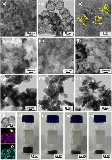
Fig. 2 shows a synthetic scheme for hollow MOPs with cyclic ethyl orthoformate-protected catechol moieties (H-MOP-CatP), H-MOP-Cat, hollow MOPs with Ru-catecholates (H-MOP-Ru), and a building block. To synthesize H-MOP-CatP, we prepared a cyclic ethyl orthoformate-protected 1,4-diiodo-2,3-catechol (2,3-ethoxymethylenedioxy-1,4-diiodobenzene) building block from 1,2-dimethoxybenzene (Fig. 2 and refer to the Experimental section for detailed procedures).30,31 After trimethylsilyl (TMS) groups were introduced to the neighboring sites of methoxy groups of 1,2-dimethoxybenzene, treatment with iodine monochloride resulted in the formation of 1,4-diiodo-2,3-dihydroxybenzene. Unfortunately, direct use of 1,4-diiodo-2,3-dihydroxybenzene as a building block for preparing H-MOP-Cat was unsuccessful, due to quenching of coupling catalysts by catechol groups. Thus, we protected catechol moieties with cyclic ethyl orthoformate (Ceof) groups to form a 2,3-ethoxymethylenedioxy-1,4-diiodobenzene building block.30,31 Using silica spheres as templates, H-MOP-CatP was obtained through the Sonogashira–Hagihara coupling of 1,3,5-triethynylbenzene and 1.5 eq. of 2,3-ethoxymethylenedioxy-1,4-diiodobenzene and successive silica etching by treatment with aqueous HF solution. Acid-catalyzed hydrolysis of Ceof protecting groups in the H-MOP-CatP resulted in the formation of H-MOP-Cat. Ru species were then incorporated into H-MOP-Cat through treatment with RuCl3 trihydrate to form H-MOP-Ru.The morphologies of H-MOP-CatP, H-MOP-Cat, and H-MOP-Ru were investigated using SEM and TEM analysis (Fig. 3 and S1 in the ESI†). The SEM and TEM images of H-MOP-CatP showed hollow spheres with an average diameter of 195 nm and an average shell thickness of 22 nm (Fig. 3a and d). After hydrolysis of Ceof protecting groups in H-MOP-CatP and Ru coordination to catechol moieties in H-MOP-Cat, the resultant H-MOP-Cat and H-MOP-Ru retained their original hollow morphologies (Fig. 3b, c, e, and f). EDS-based elemental mapping analysis of H-MOP-Ru showed incorporation of Ru into H-MOP-Cat (Fig. 3g).
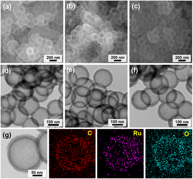 | ||
| Fig. 3 SEM and TEM images of (a and d) H-MOP-CatP, (b and e) H-MOP-Cat, and (c and f) H-MOP-Ru. (g) EDS-based elemental mapping images of H-MOP-Ru. | ||
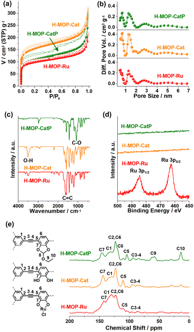
The surface area and microporosity of the materials were characterized by analyzing N2 adsorption–desorption isotherm curves based on BET theory and the NL-DFT method (Fig. 4a and b and Table S1 in the ESI†). The surface area and micropore volume (Vmic) of H-MOP-CatP were measured to be 399 m2 g−1 and 0.088 cm3 g−1, respectively. Interestingly, the surface area and Vmic of H-MOP-Cat increased significantly to 569 m2 g−1 and 0.14 cm3 g−1, respectively, indicating successful deprotection of Ceof groups. Ru coordination to H-MOP-Cat induced a decrease of the surface area and Vmic of H-MOP-Ru to 361 m2 g−1 and 0.087 cm3 g−1, respectively. PXRD studies indicated that H-MOP-CatP, H-MOP-Cat, and H-MOP-Ru are amorphous (Fig. S2 in the ESI†).
The chemical structures of the materials were characterized by IR, XPS, and solid state 13C NMR studies (Fig. 4c–e). While the IR spectrum of H-MOP-CatP showed C-O vibration peaks of Ceof groups at 1081 cm−1, H-MOP-Cat showed a decrease of C–O vibrations and appearance of O-H vibrations at 3515 cm−1, due to the generation of catechol moieties.33–35 Ru coordination induced a shift of C![[double bond, length as m-dash]](https://www.rsc.org/images/entities/char_e001.gif) C vibration peaks from 1581 cm−1 (H-MOP-Cat) to 1601–1623 cm−1 (H-MOP-Ru). XPS analysis of H-MOP-Ru showed Ru 3p1/2 and 3p3/2 orbital peaks at 484.6 and 462.5 eV, respectively, confirming the formation of Ru(III)–Cl species (Fig. 4d).36
C vibration peaks from 1581 cm−1 (H-MOP-Cat) to 1601–1623 cm−1 (H-MOP-Ru). XPS analysis of H-MOP-Ru showed Ru 3p1/2 and 3p3/2 orbital peaks at 484.6 and 462.5 eV, respectively, confirming the formation of Ru(III)–Cl species (Fig. 4d).36
The 13C NMR spectrum of H-MOP-CatP showed 13C peaks of Ceof groups at 13.5, 60.2, and 119.6 ppm, in addition to aromatic peaks at 104.3, 123.4, 132.9, and 146.0 ppm and alkyne peaks at 85.0–93.6 ppm (Fig. 4e). In the 13C NMR spectrum of H-MOP-Cat, Ceof groups disappeared, indicating successful deprotection of Ceof groups. H-MOP-Ru showed significant changes of aromatic peaks at 110.5–142.6 ppm, due to Ru coordination to catechol moieties.
TGA curves indicated that H-MOP-Ru is thermally stable up to 275 °C (Fig. S3 in the ESI†). Using H-MOP-Ru as a precursor material, HN-Ru/RuO2 was obtained by heat-treatment at 500 °C for 4 h under air (Fig. 5). As a control material, commercial Ru/RuO2 nanopowders (A-Ru/RuO2, Aldrich Chem Co., Cat. no. 238058) were obtained. In addition, control Ru/RuO2 nanoparticles (N-Ru/RuO2) were prepared by heat-treatment of RuCl3 trihydrate at 500 °C for 4 h under air. Considering the existence of Pd in HN-Ru/RuO2, originating from the Pd catalyst used in the synthesis of the MOP, we prepared N1-Ru/RuO2 by the heat treatment of a mixture of RuCl3 trihydrate and (PPh3)2PdCl2 at 500 °C for 4 h under air. To match with the content of Pd in HN-Ru/RuO2, we systematically scanned the amount of (PPh3)2PdCl2 for the synthesis of N1-Ru/RuO2 (refer to the Experimental section for the amounts of Ru and Pd precursors).
SEM and TEM analysis of HN-Ru/RuO2 showed hollow nanoparticles with an average diameter of 61 nm (Fig. 6a and b). Interestingly, the shells of HN-Ru/RuO2 consisted of nanoparticles with sizes of 6–7 nm (Fig. 6b). Considering the diameter (195 nm) and shell thickness (22 nm) of the precursor material (H-MOP-Ru), the reduced sizes of HN-Ru/RuO2 imply significant shrinkage of hollow MOP materials to HN-Ru/RuO2, due to the combustion-induced removal of carbon. HR-TEM analysis of HN-Ru/RuO2 clearly confirmed that hollow shells consist of small nanoparticles (Fig. 6c). The (110) and (200) crystalline planes of rutile RuO2 were exclusively observed in the HR-TEM images of HN-Ru/RuO2 with inter-crystalline plane distances of 0.32 and 0.23 nm, respectively (Fig. 6c).
The SEM and TEM images of commercial A-Ru/RuO2 showed spherical nanoparticles with a relatively broad size distribution in the range of 25–70 nm (Fig. 6d and g). In comparison, the SEM and TEM images of N-Ru/RuO2 showed short rod-like nanomaterials with sizes of ∼35 nm × 75 nm (Fig. 6e and h). N1-Ru/RuO2 also showed irregular granules with a broad size distribution in the range of 7–75 nm (Fig. 6f and i). EDS-based elemental mapping images of HN-Ru/RuO2 indicated a homogeneous distribution of Ru and O over the materials (Fig. 6j). Interestingly, due to the hollow structural nature of HN-Ru/RuO2, its bulk density was much lower than those of A-Ru/RuO2, N-Ru/RuO2, and N1-Ru/RuO2 (refer to Fig. 6k–n showing 40 mg powder in each vial).
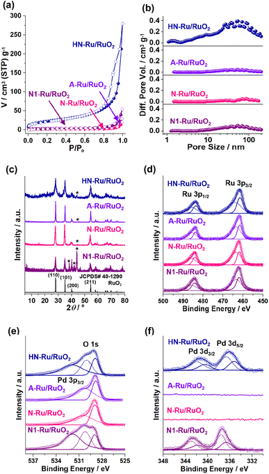
Fig. 7 shows the physical and chemical features of Ru/RuO2 materials. HN-Ru/RuO2 showed a high surface area of 80 m2 g−1 and mesoporosity with a total pore volume (Vt) of 0.18 cm3 g−1, due to its nanoparticulate shells and hollow structure (Fig. 7a and b and Table S1 in the ESI†). In comparison, A-Ru/RuO2, N-Ru/RuO2, and N1-Ru/RuO2 showed relatively lower surface areas of 10, 6, and 11 m2 g−1 and poor porosity with Vt of 0.019, 0.010, and 0.031 cm3 g−1, respectively. The PXRD pattern of HN-Ru/RuO2 showed diffraction peaks at 28.1, 35.1, 40.0, and 54.5° (2θ), corresponding to the (110), (101), (200), and (211) crystalline planes of rutile RuO2 (JCPDS# 40-1290), respectively (Fig. 7c). While A-Ru/RuO2, N-Ru/RuO2, and N1-Ru/RuO2 also indicated rutile RuO2, interestingly, all Ru/RuO2 materials showed additional metallic Ru peaks (JCPDS# 65-1863) at 38.3, 41.9, and 43.9° (2θ).
The chemical structures of Ru/RuO2 materials were characterized by XPS studies (Fig. 7d–f and S4 in the ESI†). The Ru 3p1/2 and 3p3/2 orbital peaks of HN-Ru/RuO2 indicated a mixture of Ru(IV) at 485.7 and 464.1 eV and zerovalent Ru at 483.6 and 461.5 eV, respectively (Fig. 7d).37 The O 1 s orbital peaks of HN-Ru/RuO2 were observed at 528.9 and 530.0 eV, corresponding to inner and surface oxides of RuO2, respectively, in addition to a Pd 3p3/2 orbital peak at 531.9 eV (Fig. 7e).38 According to ICP analysis, the molar ratio of Ru and Pd in HN-Ru/RuO2 was measured to be 83![[thin space (1/6-em)]](https://www.rsc.org/images/entities/char_2009.gif) :
:![[thin space (1/6-em)]](https://www.rsc.org/images/entities/char_2009.gif) 17. The corresponding Pd 3d3/2 and 3d5/2 orbital peaks of HN-Ru/RuO2 were observed at 341.4 and 336.2 eV, respectively, indicating main PdO species (Fig. 7f).39
17. The corresponding Pd 3d3/2 and 3d5/2 orbital peaks of HN-Ru/RuO2 were observed at 341.4 and 336.2 eV, respectively, indicating main PdO species (Fig. 7f).39
While the Ru 3p1/2 and 3p3/2 orbital peaks of A-Ru/RuO2 showed a mixture of Ru(IV) at 485.7 and 463.6 eV and zerovalent Ru at 483.8 and 461.6 eV, the O 1 s orbital peaks appeared at 528.8 and 530.3 eV (Fig. 7d and e). Similarly, while the Ru 3p1/2 and 3p3/2 orbital peaks of N-Ru/RuO2 indicated a mixture of Ru(IV) at 486.0 and 463.6 eV and zerovalent Ru at 484.1 and 461.8 eV, the O 1 s orbital peaks were observed at 528.9 and 530.4 eV (Fig. 7d and e).
In the XPS spectrum of N1-Ru/RuO2, the Ru 3p1/2 and 3p3/2 orbital peaks of Ru(IV) were observed at 485.7 and 463.4 eV, respectively, in addition to zerovalent Ru species at 484.2 and 461.9 eV.36,37 Similar to those of HN-Ru/RuO2, two O 1 s orbital peaks of N1-Ru/RuO2 were observed at 529.0 and 530.2 eV, in addition to the Pd 3p3/2 orbital peak at 531.9 eV (Fig. 7d and e).38 The molar ratio of Ru and Pd of N1-Ru/RuO2 was analyzed to be 82![[thin space (1/6-em)]](https://www.rsc.org/images/entities/char_2009.gif) :
:![[thin space (1/6-em)]](https://www.rsc.org/images/entities/char_2009.gif) 18 by ICP analysis, which was adjusted as a control material of HN-Ru/RuO2 through systematic amount scanning of Pd precursors. The Pd 3d3/2 and Pd 3d5/2 orbital peaks of N1-Ru/RuO2 were observed at 342.7 and 337.4 eV, respectively, indicating that the main Pd species is PdO2 (Fig. 7f).39
18 by ICP analysis, which was adjusted as a control material of HN-Ru/RuO2 through systematic amount scanning of Pd precursors. The Pd 3d3/2 and Pd 3d5/2 orbital peaks of N1-Ru/RuO2 were observed at 342.7 and 337.4 eV, respectively, indicating that the main Pd species is PdO2 (Fig. 7f).39
Next, the electrocatalytic performance of the Ru/RuO2 materials for the OER was studied by linear sweep voltammetry using three-electrode electrochemical cells (Fig. 8). When acidic electrolyte was used, the OER activities of Ru/RuO2 materials were not stable, due to their facilitated dissolution.40–42 Thus, we focused on the OER performance in basic electrolyte (1.0 M KOH). During measurements, the electrolyte was purged with O2 gas. Fig. 8a shows the OER polarization curves when the OER is electrochemically catalyzed by Ru/RuO2 materials, indicating that HN-Ru/RuO2 revealed OER activity at significantly lower potential (vs. RHE) than A-Ru/RuO2, N-Ru/RuO2, and N1-Ru/RuO2.
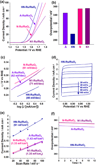 | ||
| Fig. 8 Electrocatalytic performance of HN-Ru/RuO2, A-Ru/RuO2, N-Ru/RuO2, and N1-Ru/RuO2 for the OER in 1.0 M KOH: (a) OER polarization curves, (b) overpotentials at 10 mA cm−2, (c) Tafel plots, (d–e) scan rate dependent cyclic voltammograms (refer to the cyclic voltammograms in Fig. S5 in the ESI† for other control materials) and calculated capacitances, and (f) durability tests measured with potentiometry at a current density of 10 mA cm−2. | ||
While the overpotential @ 10 mA cm−2 (η10) of HN-Ru/RuO2 was measured to be 295 mV, those of A-Ru/RuO2, N-Ru/RuO2, and N1-Ru/RuO2 were analyzed to be 345, 355, and 356 mV, respectively (Fig. 8b). Comparing the electrocatalytic performance of HN-Ru/RuO2 with that of N1-Ru/RuO2 or comparing the OER activity of N-Ru/RuO2 with that of N1-Ru/RuO2, it can be speculated that the effect of Pd in HN-Ru/RuO2 and N1-Ru/RuO2 is not significant for the observed performance parameters of electrocatalytic OER, indicating that the hollow and nanoparticulate feature of HN-Ru/RuO2 induced beneficial electrocatalytic performance. It has been reported that in alkaline electrolyte, OH− is oxidized to oxygen and water through the electrocatalytic OER process.43 Thus, the effective coordination of *OOH and *OH toward RuO2 electrocatalysts is critical for the high activity toward the OER.43 Moreover, it has been reported that while the bare surface of RuO2 is inert for electrocatalytic OER, defective surface oxides are actually active.43 Thus, considering all of this, we suggest that the superior electrocatalytic performance of HN-Ru/RuO2 is attributable to an enhanced defective surface effect of HN-Ru/RuO2, originating from the hollow structure and nanoparticulate shells.
Fig. 8c shows Tafel plots with Tafel slopes of 46, 62, 61, and 71 mV dec−1 for HN-Ru/RuO2, A-Ru/RuO2, N-Ru/RuO2, and N1-Ru/RuO2, respectively. The much smaller Tafel slope of HN-Ru/RuO2 than those of A-Ru/RuO2, N-Ru/RuO2, and N1-Ru/RuO2 indicates its faster electrocatalytic OER process.43 The turnover frequency (TOF) of HN-Ru/RuO2 was calculated to be 0.86 s−1 @ 0.30 V, much faster that those (0.15–0.20 s−1 @ 0.30 V) of control Ru/RuO2 materials. We suggest that the faster electrocatalytic performance of HN-Ru/RuO2 resulted from the enhanced surface area, due to its hollow structure and nanoparticulate shells.
Fig. 8d–e show the scan-rate dependent cyclic voltammograms (refer to Fig. S5 in the ESI† for cyclic voltammograms of the electrocatalytic OER process by A-Ru/RuO2, N-Ru/RuO2, and N1-Ru/RuO2), indicating that HN-Ru/RuO2 revealed much higher capacitances (Cdl: 61 mF cm−2) than control Ru/RuO2 materials (Cdl: 1.33–1.43 mF cm−2). The corresponding electrochemical active surface area (ECSA: Cdl/Cs, Cdl with an area of 0.164 cm2, Cs: 0.040 mF cm−2) of HN-Ru/RuO2 was calculated to be 2.5 × 102 cm2, much higher than the 5.9–5.5 cm2 of the control Ru/RuO2 materials. According to electrochemical impedance spectroscopy (EIS), the charge transfer resistance (Rct: 29.2 Ω) of HN-Ru/RuO2 was significantly lower than those of A-Ru/RuO2 (39.3 Ω), N-Ru/RuO2 (45.5 Ω), and N1-Ru/RuO2 (47.5 Ω), indicating the effective interaction of HN-Ru/RuO2 with substrates (Fig. S6 in the ESI†).
Finally, the durability of HN-Ru/RuO2 was studied with potentiometry for overpotentials at 10 mA cm−2, revealing >98% retention of the original electrocatalytic performance for the OER during 12 h (Fig. 8f). After the durability test, TEM studies on the HN-Ru/RuO2 revealed the complete retention of their original hollow and nanoparticulate structure (Fig. S7 in the ESI†). Furthermore, XPS analysis of the recovered HN-Ru/RuO2 indicated a slight increase in Ru(IV) species from 59% to 64%, accompanied by a slight increase in surface oxygen from 58% to 62% (Fig. S7 in the ESI†). Interestingly, HN-Ru/RuO2 and N1-Ru/RuO2 showed slightly better durability than A-Ru/RuO2 and N-Ru/RuO2, possibly due to the Pd content in the corresponding catalysts.
Recently, various RuO2-based systems have been studied as electrocatalysts for the OER in alkaline electrolytes in the literature.44–55 Table S2 in the ESI† summarizes the electrocatalytic performance of recent RuO2 materials in alkaline electrolyte (KOH solution) for the OER. For example, RuO2 nanorods and nanoplates have been prepared to show η10 values of 320–400 mV and Tafel slopes of 82.5–86 mV dec−1.44–55 Introduction of additional metal oxides to RuO2 has improved electrocatalytic performance, due to enhanced defects or cooperative catalysis. For example, RuO2/Co3O4 and RuO2/CeO2 nanocomposites have been engineered to show the improved η10 values of 302–350 mV and Tafel slopes of 74–74.37 mV dec−1.44–55 For further improvement of OER performance, additional carbon materials such as carbon nanotubes and doped-graphenes have been incorporated into RuO2, showing η10 values of 209–255 mV and Tafel slopes of 56–64 mV dec−1.44–55 It should be noted that RuO2 nanoparticles without additional carbon materials showed η10 values of 302–400 mV and Tafel slopes of 74–86 mV dec−1 in the literature (Table S2 in the ESI†). While the η10 of 295 mV and the Tafel slope of 46 mV dec−1 are not a state-of-the-art world-record, the electrocatalytic performance of HN-Ru/RuO2 is quite inspiring, considering that it resulted from morphology engineering of electrocatalysts. It is also noteworthy that while hollow RuO2 spheres have been engineered, the hollow diameter (61 nm) of HN-Ru/RuO2 is significantly smaller than those (220–660 nm) in the literature.10,56–59
Conclusions
Hollow Ru/RuO2 nanoparticles with nanoparticulate shells were engineered using hollow MOPs as templates. Using catechol moieties as anchoring groups, the Ru species could be easily incorporated into hollow MOPs. Heat-treatment of H-MOP-Ru under air resulted in the formation of hollow Ru/RuO2 nanoparticles with nanoparticulate shells. While the diameter of hollow Ru/RuO2 was measured to be 61 nm, the shells of HN-Ru/RuO2 consisted of 6–7 nm nanoparticles. Due to its hollow structure and nanoparticulate shells, HN-Ru/RuO2 showed a high surface area of 80 m2 g−1 and porosity, resulting in superior electrocatalytic performance for the OER to control Ru/RuO2 nanoparticles. We believe that while HN-Ru/RuO2 can be utilized as an HER electrocatalyst60–62 (Fig. S8 in the ESI†), the H-MOP with catechol moieties in this work can be further applied for the development of electrocatalytic systems for the OER or HER through exploring various metal species.Author contributions
S. U. Son: conceptualization, supervision, writing the original draft, and review and editing. Y. Myung: supervision, investigation, and formal synthesis. K. Cho, J. Y. Jang, and Y.-J. Ko: investigation and formal analysis.Conflicts of interest
There are no conflicts to declare.Acknowledgements
This work was supported by a National Research Foundation of Korea (NRF) grant (RS-2023-00208797) funded by the Ministry of Science and ICT, Republic of Korea.Notes and references
- K. Kohse-Höinghaus, Chem. Rev., 2023, 123, 5139–5219 CrossRef PubMed
.
- Z. Abdin, N. A. Khafaf, B. McGrath, K. Catchpole and E. Gray, Sustainable Energy Fuels, 2023, 7, 2042–2062 RSC
.
-
(a) B. You and Y. Sun, Acc. Chem. Res., 2018, 51, 1571–1580 CrossRef CAS PubMed
; (b) Y. Kang, O. Cretu, J. Kikkawa, K. Kimoto, H. Nara, A. S. Nugraha, H. Kawamoto, M. Eguchi, T. Liao, Z. Sun, T. Asahi and Y. Yamauchi, Nat. Commun., 2023, 14, 4182 CrossRef CAS PubMed
; (c) H. Zhang, W. Wang, Z. Dai, Y. Zhu, M. Cheng, B. Zhang, Y. Feng, Y. Zhang and G. Zhang, J. Mater. Chem. A, 2023, 11, 14674–14681 RSC
.
-
(a) J. Jayabharathi, B. Karthikeyan, B. Vishunu and S. Sriram, Phys. Chem. Chem. Phys., 2023, 25, 8992–9019 RSC
; (b) Y. Li, W. Wang, M. Cheng, Y. Feng, X. Han, Q. Qian, Y. Zhu and G. Zhang, Adv. Mater., 2023, 35, 2206351 CrossRef CAS PubMed
; (c) Y. Kang, Y. Guo, J. Zhao, B. Jiang, J. Guo, Y. Tang, H. Li, V. Malgras, M. A. Amin, H. Nara, Y. Sugahara, Y. Yamauchi and T. Asahi, Small, 2022, 18, 2203411 CrossRef CAS PubMed
; (d) Q. Qian, Y. Li, Y. Liu and G. Zhang, Appl. Catal., B, 2020, 266, 118642 CrossRef CAS
; (e) Q. Qian, Y. Li, Y. Liu, L. Yu and G. Zhang, Adv. Mater., 2019, 31, 1901139 CrossRef PubMed
.
- H. Sun and W. Jung, J. Mater. Chem. A, 2021, 9, 15506–15521 RSC
.
- C. Wang, L. Jin, H. Shang, H. Xu, Y. Shiraishi and Y. Du, Chin. Chem. Lett., 2021, 32, 2108–2116 CrossRef CAS
.
- Y. Li, Y. Wu, T. Li, M. Lu, Y. Chen, Y. Cui, J. Gao and G. Qian, Carbon Energy, 2023, 5, e265 CrossRef CAS
.
- X. Cao, J. Huo, L. Li, J. Qu, Y. Zhao, W. Chen, C. Liu, H. Liu and G. Wang, Adv. Energy Mater., 2022, 12, 2202119 CrossRef CAS
.
- G. Prieto, H. Tüysüz, N. Duyckaerts, J. Knossalla and G.-H. Wang, Chem. Rev., 2016, 116, 14056–14119 CrossRef CAS PubMed
.
- F. Li, D.-M. Tang, T. Zhang, K. Liao, P. He, D. Golberg, A. Yamada and H. Zhou, Adv. Energy Mater., 2015, 5, 1500294 CrossRef
.
- W. Zhang, H. Zuo, Z. Cheng, Y. Shi, Z. Guo, N. Meng, A. Thomas and Y. Liao, Adv. Mater., 2022, 34, 2104952 CrossRef CAS PubMed
.
- K. Amin, N. Ashraf, L. Mao, C. F. J. Faul and Z. Wei, Nano Energy, 2021, 85, 105958 CrossRef CAS
.
- M. Khakbaz, A. Ghaemi and G. M. M. Sadeghi, Polym. Chem., 2021, 12, 6962–6997 RSC
.
- J.-S. M. Lee and A. I. Cooper, Chem. Rev., 2020, 120, 2171–2214 CrossRef CAS PubMed
.
- S. Kramer, N. R. Bennedsen and S. Kegnæs, ACS Catal., 2018, 8, 6961–6982 CrossRef CAS
.
- M. H. Weston, G. W. Peterson, M. A. Browe, P. Jones, O. K. Farha, J. T. Hupp and S. T. Nguyen, Chem. Commun., 2013, 49, 2995–2997 RSC
.
- K. K. Tanabe, N. A. Siladke, E. M. Broderick, T. Kobayashi, J. F. Goldston, M. H. Weston, O. K. Farha, J. T. Hupp, M. Pruski, E. A. Mader, M. J. A. Johnson and S. T. Nguyen, Chem. Sci., 2013, 4, 2483–2489 RSC
.
- S. J. Kraft, R. H. Sánchez and A. S. Hock, ACS Catal., 2013, 3, 826–830 CrossRef CAS
.
- R. K. Totten, M. H. Weston, J. T. Park, O. K. Farha and J. T. Hupp, ACS Catal., 2013, 3, 1454–1459 CrossRef CAS
.
- S. J. Kraft, B. Hu, G. Zhang, J. T. Miller and A. S. Hock, Eur. J. Inorg. Chem., 2013, 2013, 3972–3977 CrossRef CAS
.
- K. K. Tanabe, M. S. Ferrandon, N. A. Siladke, S. J. Kraft, G. Zhang, J. Niklas, O. G. Poluektov, S. J. Lopykinski, E. E. Bunel, T. R. Krause, J. T. Miller, A. S. Hock and S. T. Nguyen, Angew. Chem., Int. Ed., 2014, 53, 12055–12058 CrossRef CAS PubMed
.
- M. H. Weston, Y. J. Colon, Y.-S. Bae, S. J. Garibay, R. Q. Snurr, O. K. Farha, J. T. Hupp and S. T. Nguyen, J. Mater. Chem. A, 2014, 2, 299–302 RSC
.
- S. J. Kraft, G. Zhang, D. Childers, F. Dogan, J. T. Miller, S. T. Nguyen and A. S. Hock, Organometallics, 2014, 33, 2517–2522 CrossRef CAS
.
- J. Camacho-Bunquin, N. A. Siladke, G. Zhang, J. Niklas, O. G. Poluektov, S. T. Nguyen, J. T. Miller and A. S. Hock, Organometallics, 2015, 34, 947–952 CrossRef CAS
.
- J. Camacho-Bunquin, M. Ferrandon, U. Das, F. Dogan, C. Liu, C. Larsen, A. E. Platero-Prats, L. A. Curtiss, A. S. Hock, J. T. Miller, S. T. Nguyen, C. L. Marshall, M. Delferro and P. C. Stair, ACS Catal., 2017, 7, 689–694 CrossRef CAS
.
- K. Cho, S. M. Lee, H. J. Kim, Y.-J. Ko, E. J. Kang and S. U. Son, Chem.–Eur. J., 2020, 26, 788–794 CrossRef CAS PubMed
.
- K. Cho, C. W. Kang, S. H. Ryu, J. Y. Jang and S. U. Son, J. Mater. Chem. A, 2022, 10, 6950–6964 RSC
.
- J. Y. Jang, G. H. Kim, Y.-J. Ko, K. C. Ko and S. U. Son, Polym. Chem., 2023, 14, 2958–2963 RSC
.
- J. Chun, S. Kang, N. Park, E. J. Park, X. Jin, K.-D. Kim, H. O. Seo, S. M. Lee, H. J. Kim, Y. H. Kwon, Y.-K. Park, J. M. Kim, Y. D. Kim and S. U. Son, J. Am. Chem. Soc., 2014, 136, 6786–6789 CrossRef CAS PubMed
.
- Z. Zhu and T. M. Swager, Org. Lett., 2001, 3, 3471–3474 CrossRef CAS PubMed
.
- N. Weibel, A. Blaszczyk, C. von Hänisch, M. Mayor, I. Pobelov, T. Wandlowski, F. Chen and N. Tao, Eur. J. Org Chem., 2008, 2008, 136–149 CrossRef
.
- W. Stöber, A. Fink and E. Bohn, J. Colloid Interface Sci., 1968, 126, 62–69 CrossRef
.
- M. H. Weston, O. K. Farha, B. G. Hauser, J. T. Hupp and S. T. Nguyen, Chem. Mater., 2012, 24, 1292–1296 CrossRef CAS
.
- H. Qian, Q. He, J. Zheng, S. Li and S. Zhang, Polymer, 2014, 55, 550–555 CrossRef CAS
.
- M. Henrion, Y. Mohr, K. Janssens, S. Smolders, A. L. Bugaev, O. A. Usoltsev, E. A. Quadrelli, F. M. Wisser, D. E. De Vos and J. Canivet, ChemCatChem, 2022, 14, e202200649 CrossRef CAS
.
- D. J. Morgan, Surf. Interface Anal., 2015, 47, 1072–1079 CrossRef CAS
.
- W. Wang, S. Guo, I. Lee, K. Ahmed, J. Zhong, Z. Favors, F. Zaera, M. Ozkan and C. S. Ozkan, Sci. Rep., 2014, 4, 4452 CrossRef PubMed
.
- B. K. Manna, P. Panda, R. Mishra and S. Barman, Energy Fuels, 2023, 37, 5613–5622 CrossRef CAS
.
- B. Qi, L. Di, W. Xu and X. Zhang, J. Mater. Chem. A, 2014, 2, 11885–11890 RSC
.
- C. Roy, R. R. Rao, K. A. Stoerzinger, J. Hwang, J. Rossmeisl, I. Chorkendorff, Y. Shao-Horn and I. E. L. Stephens, ACS Energy Lett., 2018, 3, 2045–2051 CrossRef CAS
.
- S. Cherevko, S. Geiger, O. Kasian, N. Kulyk, J. P. Grote, A. Savan, B. R. Shrestha, S. Merzlikin, B. Breitbach, A. Ludwig and K. J. J. Mayrhofer, Catal. Today, 2016, 262, 170–180 CrossRef CAS
.
- T. P. Luxton, M. J. Eick and K. G. Scheckel, J. Colloid Interface Sci., 2011, 359, 30–39 CrossRef CAS PubMed
.
- A. Raveendran, M. Chandran and R. A. Dhanusuraman, RSC Adv., 2023, 13, 3843–3876 RSC
.
- K. Xie, W. Xia, J. Masa, F. Yang, P. Weide, W. Schuhmann and M. Muhler, J. Energy Chem., 2016, 25, 282–288 CrossRef
.
- H.-S. Park, E. Seo, J. Yang, Y. Lee, B.-S. Kim and H.-K. Song, Sci. Rep., 2017, 7, 7150 CrossRef PubMed
.
- C.-Z. Yuan, Y.-F. Jiang, Z.-W. Zhao, S.-J. Zhao, X. Zhou, T.-Y. Cheang and A.-W. Xu, ACS Sustainable Chem. Eng., 2018, 6, 11529–11535 CrossRef CAS
.
- R. Jiang, D. T. Tran, J. Li and D. Chu, Energy Environ. Mater., 2019, 2, 201–208 CrossRef CAS
.
- H.-S. Park, J. Yang, M. K. Cho, Y. Lee, S. Cho, S.-D. Yim, B.-S. Kim, J. H. Jang and H.-K. Song, Nano Energy, 2019, 55, 49–58 CrossRef CAS
.
- M. Zhang, J. Chen, H. Li, P. Cai, Y. Li and Z. Wen, Nano Energy, 2019, 61, 576–583 CrossRef CAS
.
- S. M. Galani, A. Mondal, D. N. Srivastava and A. B. Panda, Int. J. Hydrogen Energy, 2020, 45, 18635–18644 CrossRef CAS
.
- Z. Fan, F. Liao, H. Shi, Y. Liu, M. Shao and Z. Kang, Inorg. Chem. Front., 2020, 7, 2188–2194 RSC
.
- X. Gao, J. Chen, X. Sun, B. Wu, B. Li, Z. Ning, J. Li and N. Wang, ACS Appl. Nano Mater., 2020, 3, 12269–12277 CrossRef CAS
.
- T. Yu, G. Xu, G. Qian, J. Chen, H. Zhang, L. Luo and S. Yin, ACS Sustainable Chem. Eng., 2020, 8, 17520–17526 CrossRef CAS
.
- B.-Y. Guo, X.-Y. Zhang, X. Ma, T.-S. Chen, Y. Chen, M.-L. Wen, J.-F. Qin, J. Nan, Y.-M. Chai and B. Dong, Int. J. Hydrogen Energy, 2020, 45, 9575–9582 CrossRef CAS
.
- S. Sarkar, D. Mukherjee, R. Harini and G. Nagaraju, J. Mater. Sci., 2022, 57, 7680–7693 CrossRef CAS
.
- Z. Peng, X. Liu, H. Meng, Z. Li, B. Li, Z. Liu and S. Liu, ACS Appl. Mater. Interfaces, 2017, 9, 4577–4586 CrossRef PubMed
.
- H. Kwon, D. Hong, I. Ryu and S. Yim, ACS Appl. Mater. Interfaces, 2017, 9, 7412–7423 CrossRef CAS PubMed
.
- W.-J. Lee, Y.-G. Chun, S.-J. Jang, S.-M. Paek and J.-M. Oh, J. Alloys Compd., 2017, 711, 611–616 CrossRef CAS
.
- X. Wu, Y. Zeng, H. Gao, J. Su, J. Liu and Z. Zhu, J. Mater. Chem. A, 2013, 1, 469–472 RSC
.
- J. Zhang, X. Mao, S. Wang, L. Liang, M. Cao, L. Wang, G. Li, Y. Xu and X. Huang, Angew. Chem., Int. Ed., 2022, 61, e202116867 CrossRef CAS PubMed
.
- Q. Lu, A.-L. Wang, H. Cheng, Y. Gong, Q. Yun, N. Yang, B. Li, B. Chen, Q. Zhang, Y. Zong, L. Gu and H. Zhang, Small, 2018, 14, 1801090 CrossRef PubMed
.
- W. Li, Y. Liu, M. Wu, X. Feng, S. A. T. Redfern, Y. Shang, X. Yong, T. Feng, K. Wu, Z. Liu, B. Li, Z. Chen, J. S. Tse, S. Lu and B. Yang, Adv. Mater., 2018, 30, 1800676 CrossRef PubMed
.
Footnotes |
| † Electronic supplementary information (ESI) available: SEM images of MOP and Ru/RuO2 materials, PXRD patterns of MOP materials, XPS analysis, cyclic voltammograms of Ru/RuO2 materials, EIS results, table of the physical features of MOP and Ru/RuO2 materials, and OER performance survey table of RuO2 materials. See DOI: https://doi.org/10.1039/d3na00899a |
| ‡ These authors contributed equally to this work. |
| This journal is © The Royal Society of Chemistry 2024 |

