
 Open Access Article
 This Open Access Article is licensed under a Creative Commons Attribution-Non Commercial 3.0 Unported Licence
Manipulation of interfacial charge dynamics for metal–organic frameworks toward advanced photocatalytic applications
Chien-Yi
Wang†
a,
Huai-En
Chang†
a,
Cheng-Yu
Wang
 *a,
Tomoyuki
Kurioka
*b,
Chun-Yi
Chen
b,
Tso-Fu
Mark Chang
b,
Masato
Sone
b and
Yung-Jung
Hsu
*acd
*a,
Tomoyuki
Kurioka
*b,
Chun-Yi
Chen
b,
Tso-Fu
Mark Chang
b,
Masato
Sone
b and
Yung-Jung
Hsu
*acd
aDepartment of Materials Science and Engineering, National Yang Ming Chiao Tung University, Hsinchu 300093, Taiwan. E-mail: chengyuwang@nycu.edu.tw; yhsu@nycu.edu.tw; yhsu@cc.nctu.edu.tw
bInstitute of Innovative Research, Tokyo Institute of Technology, Kanagawa 226-8503, Japan. E-mail: kurioka.t.aa@m.titech.ac.jp
cCenter for Emergent Functional Matter Science, National Yang Ming Chiao Tung University, Hsinchu 300093, Taiwan
dInternational Research Frontiers Initiative, Institute of Innovative Research, Tokyo Institute of Technology, Kanagawa 226-8503, Japan
First published on 16th November 2023
Abstract
Compared to other known materials, metal–organic frameworks (MOFs) have the highest surface area and the lowest densities; as a result, MOFs are advantageous in numerous technological applications, especially in the area of photocatalysis. Photocatalysis shows tantalizing potential to fulfill global energy demands, reduce greenhouse effects, and resolve environmental contamination problems. To exploit highly active photocatalysts, it is important to determine the fate of photoexcited charge carriers and identify the most decisive charge transfer pathway. Methods to modulate charge dynamics and manipulate carrier behaviors may pave a new avenue for the intelligent design of MOF-based photocatalysts for widespread applications. By summarizing the recent developments in the modulation of interfacial charge dynamics for MOF-based photocatalysts, this minireview can deliver inspiring insights to help researchers harness the merits of MOFs and create versatile photocatalytic systems.
 Chien-Yi Wang | Chien-Yi Wang received his bachelor's degree in Industrial Engineering and Management from National Yang Ming Chiao Tung University, Taiwan, in 2020. He is presently a PhD student in Department of Materials Science and Engineering at National Yang Ming Chiao Tung University under the supervision of Professor Yung-Jung Hsu. He is currently working on the research topics of metal–organic frameworks and their heterostructures for applications in photocatalysis and electrocatalysis. |
 Huai-En Chang | Huai-En Chang received his bachelor's degree in Materials Science and Engineering from National Yang Ming Chiao Tung University, Taiwan, in 2019. Currently, he is pursuing his PhD degree under the supervision of Prof. Yung-Jung Hsu in the Department of Materials Science and Engineering at National Yang Ming Chiao Tung University. He specializes in the synthesis and characterizations of core–shell and yolk–shell nanostructures comprising metal core/yolk and semiconductor shell, as well as the applications in the field of photocatalysis and environmental purification. |
 Cheng-Yu Wang | Cheng-Yu Wang is the Associate Professor at the Department of Materials Science and Engineering, National Yang Ming Chiao Tung University, Taiwan. He received a bachelor's degree in Chemical Engineering and a master's degree in Materials Science and Engineering from National Taiwan University, Taiwan, and a PhD degree in Energy and Mineral Engineering from Pennsylvania State University, USA. He joined National Chiao Tung University and started an independent academic career in 2017. His research mainly involves metal–organic framework and its applications in hydrogen storage, including room-temperature adsorption and hydride dehydrogenation, CO2 capture, and CO2 reduction. |
 Tomoyuki Kurioka | Tomoyuki Kurioka was born in 1993 in Shimane, Japan. He received his bachelor's degree in March 2017 and his PhD in March 2022 from Tokyo Institute of Technology, Japan. From April 2022, he joined Professor Masato Sone and Professor Tso-Fu Mark Chang's research group, and started to work as an Assistant Professor at Institute of Innovative Research, Tokyo Institute of Technology, Japan. His research interests include fabrication of hybrid materials composed of π-conjugated polymers and various materials, mechanism studies on the dynamics of their electron transfer behaviors, and their catalytic applications toward environmentally friendly chemical reactions. |
 Chun-Yi Chen | Chun-Yi Chen received B.A.Sc. degree in chemical engineering from National Tsing Hua University in 2005, M.Eng. degree in chemical engineering from National Tsing Hua University in 2007, and PhD degree in electronic chemistry from Tokyo Institute of Technology in 2012. From 2012 to 2015, she was an Assistant Professor with Research Institute for Science and Engineering in Waseda University. From 2015 to 2023, she was a Specially Appointed Assistant Professor with Precision and Intelligence Laboratory in Tokyo Institute of Technology. Since 2023, she has been a Specially Appointed Lecturer in Tokyo Institute of Technology. |
 Tso-Fu Mark Chang | Tso-Fu Mark Chang received B.A.Sc. degree in chemical engineering and applied chemistry from the University of Toronto in 2004, M.Eng. degree in chemical engineering from National Tsing Hua University in 2007, and M.Eng. and PhD degrees in materials sciences and engineering from Tokyo Institute of Technology in 2011 and 2012, respectively. From 2007 to 2009, he was an Engineer with DuPont Taiwan. From 2012 to 2016, he was an Assistant Professor with Precision and Intelligence Laboratory in Tokyo Institute of Technology. Since 2021, he has been an Associate Professor with Institute of Innovative Research in Tokyo Institute of Technology. |
 Masato Sone | Masato Sone received his doctor degree of engineering at Tokyo Institute of Technology in 1996. He worked as a Researcher in Nippon Oil Company from 1996–2000. He was an Assistant Professor and then a Research Associate Professor at Tokyo University of Agriculture & Technology from 2000 to 2005. In 2005, he was an Associate Professor at Tokyo Institute of Technology, and he was promoted to Professor in 2017. His recent research topics include development of novel electrodeposition process towards the application of MEMS technology and the evaluation method of physical properties of the electrodeposited materials. |
 Yung-Jung Hsu | Yung-Jung Hsu is a Professor at Department of Materials Science and Engineering, National Yang Ming Chiao Tung University, Taiwan. He also serves as a Specially Appointed Professor at Institute of Innovative Research, Tokyo Institute of Technology, Japan. He received bachelor's degree and PhD degree in Chemical Engineering from National Tsing Hua University in Taiwan. After working as a postdoctoral fellow at National Tsing Hua University, he joined National Chiao Tung University and started an independent research career in 2007. His research interests include design of advanced nanostructures, investigation of interfacial charge carrier dynamics, and development of renewable energy technology. |
1. Introduction
Metal–organic frameworks (MOFs) have drawn attention as promising photocatalysts due to their unique properties, including adjustable light-harvesting over a broad range, intrinsically pronounced charge separation favorable for photoelectric conversion, and high surface area enabling easy accessibility to reactants.1–4 By combining the advantages of organic and inorganic properties, MOFs introduce themselves as an excellent platform for photocatalysis. The metal nodes occupied by coordinated organic linkers are generally less active,5,6 and can be engineered to render functional sites by defect introduction. In this regard, a workable method to supply more exposed active metal sites in MOFs is to incorporate coordinatively unsaturated open metal sites, which can effectively improve the photocatalytic performance of MOFs.7,8 Moreover, maneuvering the organic linkers can consolidate the utility of MOFs as photocatalysts; research has demonstrated that this is a reliable approach to tailoring the photocatalytic properties. For example, functionalization of organic linkers can adjust the band structure of MOFs, expanding the light absorption range to enable broadband photon harvesting. The introduction of specific functional groups can also affect the excited state dynamics of MOFs to modulate charge transfer dynamics, offering new opportunities to tailor the photocatalytic properties.9As a potential candidate for photocatalysts, MOFs possess an intriguing mechanism associated with charge carrier generation and migration. Typically, the organic linkers of MOFs act as an antenna to absorb the photon energy, producing electron–hole pairs on the lowest unoccupied molecular orbital (LUMO) and the highest occupied molecular orbital (HOMO).10 The photoexcited charge carriers can be separated through a ligand-to-metal charge transfer (LMCT) pathway for further participation in desired catalytic reactions.11,12 The efficiency of MOFs as photocatalysts depends on the electronic properties of the metal nodes and the organic ligands, which determine the light absorption range, the redox potential, and the dynamics of charge separation and transfer. By careful design and functionalization, MOFs can be tailored to optimize these properties, thus enhancing their photocatalytic performance for a wide range of applications, including dye degradation,13 water splitting,14 CO2 reduction,15 and N2 reduction.16 Interfacial charge dynamics are particularly important to the utility of MOFs as photocatalysts because they dictate charge transfer and carrier utilization, the two key processes associated with photocatalytic reactions. After light irradiation, the photoexcited charge carriers can migrate from the interior of photocatalysts to the surface and participate in redox reactions. However, considerable charge recombination, inherently competes with charge transfer processes, endangering charge carrier utilization and lowering photocatalytic activity. It is crucial to comprehend how these charge carriers are transported, trapped, and recombined to optimize the resultant photocatalytic properties.17 Knowing the fate of photoexcited charge carriers and identifying the most decisive charge transfer pathway can therefore provide critical insights into exploiting MOF-based nanostructures as photocatalysts. Methods to modulate charge dynamics and even manipulate carrier behaviors may provide new opportunities for the intelligent design of MOF-based photocatalysts for advanced applications. However, knowledge and methods to manipulate interfacial charge dynamics for MOF-based photocatalysts remain in their infancy. In pursuit of intelligent design of MOF-based photocatalysts, a comprehensive overview of research advances in this topic is necessary.
In the last three years, many reviews have been published on topics associated with MOF-based photocatalysts. These reviews mainly presented a summary of synthetic approaches,18–21 highlights of specific photocatalytic applications,14,16,22–24 and comprehensive strategies for improving photocatalytic activity.25–31 The role of interfacial charge dynamics for MOFs in photocatalytic reactions has only been highlighted in two relevant reviews, which were published in 2020.32,33 Reviews summarizing the recent developments in the modulation of the interfacial charge dynamics of MOF-based photocatalysts for activity optimization remain scarce. As depicted in Scheme 1, this minireview aims to recapitulate the recent developments in strategies and approaches that can be used to modulate the interfacial charge dynamics of MOF-based photocatalysts and optimize photocatalytic efficiency. Section 2 of this minireview introduces the fundamental principles that underlie ultrafast laser spectroscopic techniques, including time-resolved photoluminescence (PL) and transient absorption (TA) spectroscopy, to identify interfacial charge dynamics of semiconductor nanostructures. Section 3 highlights how the composition of metal ions and organic linkers affect the charge transfer dynamics of MOFs along with their implications for photocatalytic properties. Section 4 discusses approaches used to introduce heterojunctions into MOFs to modulate interfacial charge dynamics and optimize photocatalytic performance. Section 5 further highlights photocatalytic studies on covalent organic frameworks (COFs), which are analogous to MOFs except for the composition of metal nodes, to convey inspirational information. This minireview ends with new insights into tactics used to manipulate the interfacial charge dynamics of MOFs, which may help shape the future of MOF-based photocatalysts.
 | ||
| Scheme 1 Schematic illustration for engineering, photocatalysis and charge dynamics of MOF-based photocatalysts. | ||
2. Principles of time-resolved PL and TA
Ultrafast laser spectroscopic techniques have been intensively employed to inspect interfacial charge dynamics for semiconductor nanostructures, especially those used for photocatalytic reactions.17,34 By interrogating time-resolved PL and TA data as a function of time and wavelength, dynamics can be elucidated for the excited states of samples. For time-resolved PL spectroscopic measurements, the samples are usually excited by a pulsed laser of picosecond widths. The emitted photons at a selected wavelength are detected and counted as a sequence of detection events in a single-photon counting configuration. A histogram of the detection events is then established by recording the time between the excitation pulse and arriving photons, from which the time-domain PL decay data can be obtained. Because the emitted photons originate from the recombination of photoexcited electrons and holes, the kinetics of the recorded PL decay describe the lifespan of the photoexcited charge carriers. These data can be further analysed with a pseudo-first-order kinetics model to obtain a lifetime component characteristic for the fate of charge carriers that occur in the excited state before relaxing to the ground state. Due to the pseudo-first-order kinetics consideration, the reciprocal of the lifetime component equates to the rate constant in a specific carrier relaxation pathway. By analysing the time-resolved PL data, a quantitative examination of the specific charge transfer pathway can be readily carried out.35,36 However, most semiconductor nanostructures have low PL quantum yields. The quality of the recorded time-resolved PL data is therefore low; thus, further data analysis and interpretation is difficult.In addition to time-resolved PL, TA spectroscopy also adds itself into the toolbox of inspecting charge transfer dynamics for semiconductor nanostructures. The TA technique uses a pump laser of short pulses (femtosecond to nanosecond) to excite charge carriers of the samples. After a certain delay, an additional probe laser is employed to monitor the fate of these charge carriers. By varying the delay between the probe and the pump laser, the optical absorption change (ΔA) in the sample as a function of time and wavelength can be received. The ΔA profile at a specific wavelength contains dynamic information on the deactivation processes for the excited state. By carefully analyzing the ΔA profile with a delicate kinetics model, the potentially involved carrier relaxation event can be interrogated to convey quantitative information. Compared with time-resolved PL, TA can better identify specific carrier relaxation processes, especially those involving nonradiative pathways. This feature is particularly important when investigating interfacial charge dynamics for semiconductor photocatalysts because interfacial charge transfer pathways are intrinsically nonradiative. In the following sections, we summarize various approaches that have been adopted to modulate the interfacial charge dynamics of MOF-based photocatalysts. With the use of time-resolved PL and TA spectroscopy, the charge transfer dynamics of the samples can be quantitatively described to offer global feedback for further performance optimization.
3. Effect of composition
MOFs consist of metal nodes coordinated with organic linkers. By varying the metal and organic composition, the interfacial charge dynamics of MOFs can be modulated to tailor the resultant photocatalytic properties. Various modification approaches have been employed to generate MOFs with varied compositions, such as substituting central metal,37–39 replacing organic linkers,40,41 and inducing unsaturated, defective sites.42,43 We introduce several representative works in this section to emphasize the importance of the composition effect on the interfacial charge dynamics for MOF-based photocatalysts.3.1 Engineering of metal nodes
Engineering metallic sites are the perfect starting point to create MOFs with a variety of functionalities due to their modular architecture and flexibility. Introducing specific metal sites can not only facilitate interfacial charge transfer dynamics for MOFs but also endow MOFs with enriched catalytically active centres. Jiang and coworkers designed dual metal sites for MOFs composed of [Sr(NH2-BDC)(DMF)]n for applications in photocatalytic NH3 synthesis.37 Photocatalytic NH3 synthesis from N2 is a carbon-neutral strategy, although its efficiency is impeded by the activation of inert triple bonds. In N2 activation, the mechanism can be divided into two processes. The empty d orbital of the metal accepts one electron from the σg bonding orbital of N2. Afterward, the occupied d orbital back-donates another electron to the antibonding orbital of N2. Strong electron acceptance and active sites with donation capacity are needed to coordinate these two processes. The ionization potential (IP) can be viewed as a descriptor of electron acceptance and donation capacity.44 According to the theory of hard and soft acids and bases (HSAB),45 the hard acid with a high IP value possesses strong electron acceptability, while the soft acid with a low IP value prefers to donate electrons. Therefore, to enhance N2 activation, a promising strategy could involve the deliberate design of bimetallic active sites within a MOF-based photocatalyst. These bimetallic sites should exhibit distinct electron acceptability, featuring one metal with strong electron-accepting properties and another with weaker electron acceptability. This approach aims to uncouple the processes of electron acceptance and donation during the π back-donation procedure, potentially leading to more efficient N2 activation. The metals in the active state are screened by the IP in the order of Ba+ < Sr+ < Co+ < Zn+ < Ru2+ < Fe2+, classified into soft acids, borderline acids, and hard acids. In this regard, bimetallic organic framework (BMOF) combinations with gradient IP values are selected for study.
A typical scanning electron microscopy (SEM) image in Fig. 1a shows that BMOF(Sr)-0.2Fe forms a well-defined crystalline structure and exhibits a prism morphology with clear edges. The crystalline structure is well maintained, as shown by the high-resolution transmission electron microscopy (HRTEM) image in Fig. 1b. As shown in Fig. 1c, different bimetallic combinations of soft and hard acids distinctly impact the NH3 evolution rate. BMOF(Sr)-0.2Fe, BMOF(Sr)-0.2Co, BMOF(Sr)-0.2Ba, BMOF(Ru)-0.2Fe, BMOF(Co)-0.2Fe, and BMOF(Co)-0.2Zn can produce 780, 659, 292, 55, 517, and 172 μmol g−1 h−1 NH3, respectively. The BMOF samples that simultaneously contain two metal nodes with evident differences in hardness, such as BMOF(Sr)-0.2Fe, BMOF(Sr)-0.2Co, and BMOF(Co)-0.2Fe, exhibit much better photocatalytic activity than those constructed by two metal nodes with similar hardness. It can be found that the bimetal synergistic effect emerges only when an electron acceptability difference is large enough between the two kinds of metal nodes, which can be quantified by the ionization potential difference (ΔIP).
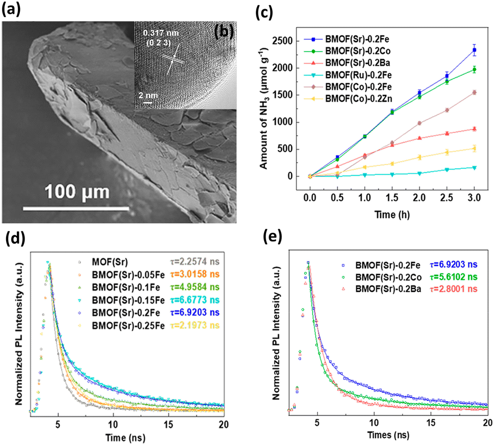 | ||
| Fig. 1 (a) SEM and (b) HRTEM images for BMOF(Sr)-0.2Fe. (c) Results of photocatalytic NH3 synthesis under white light illumination on various BMOFs samples. (d) Time-resolved PL data of MOF(Sr) and various BMOF(Sr) samples. (e) Time-resolved PL data of BMOF(Sr)-0.2Fe, BMOF(Sr)-0.2Co and BMOF(Sr)-0.2Ba. Reproduced with permission from ref. 37. Copyright 2021, American Chemical Society. | ||
Time-resolved PL analysis was conducted to explore the charge transfer behavior of BMOFs. According to the PL decay curves shown in Fig. 1d, the average PL lifetimes of MOF(Sr), BMOF(Sr)-0.05Fe, BMOF(Sr)-0.1Fe, BMOF(Sr)-0.15Fe, BMOF(Sr)-0.2Fe, and BMOF(Sr)-0.25Fe were 2.26, 3.02, 4.96, 6.68, 6.92, and 2.20 ns, respectively. This result indicated that an appropriate content of hard acid metal can lengthen the photoexcited carrier lifetime. Furthermore, the excess incorporation may form an electron trap and decrease the separation efficiency of the photoexcited charge carriers. Importantly, the ΔIP value between the bimetal nodes greatly influenced the photoexcited carrier lifetime. The large ΔIP value may have a positive effect on suppressing carrier recombination, resulting in a prolonged carrier lifetime. As shown in Fig. 1e, BMOF(Sr)-0.2Fe (soft and hard acid) exhibited a longer carrier lifetime than that of BMOF(Sr)-0.2Co (soft and borderline acid) and BMOF(Sr)-0.2Ba (soft and soft acid). The very prolonged carrier lifetime for BMOF(Sr)-0.2Fe accounted for its superior performance in photocatalytic NH3 synthesis.
Liu et al. proposed a two-step self-assembly process that is simple and effective to functionalize UiO-67(bpydc) with Ru-based photosensitizers and Co catalytic sites.38 The resulting (Co/Ru)n-UiO-67(bpydc) provided a molecular platform to enable fast multielectron injection from photosensitizers through the basal MOFs; in addition, the platform provides catalytic centres, achieving efficient syngas production from photocatalytic CO2 reduction with a yield of 13![[thin space (1/6-em)]](https://www.rsc.org/images/entities/char_2009.gif) 600 μmol g−1 (H2:CO = 2:1) in 16 h. This performance was almost 30- and 20-fold higher than that of the homogeneous counterparts of Co2+/[Ru(bpy)3]2+ and Co(bpy)/[Ru(bpy)3]2+, respectively. The results of the microstructural investigation suggested that Ru, Zr, and Co elements were uniformly distributed in the modified MOFs. The ratio of Co/Ru significantly influenced the ratio of the produced H2/CO, which can be systematically adjusted from 3.0 to 1.9. Compared to (Co/Ru)2.4-UiO-67(bpydc), the homogeneous counterparts, i.e., Co2+/[Ru(bpy)3]2+ and Co(bpy)/[Ru(bpy)3]2+, exhibited much lower yields of CO/H2 production (Fig. 2a). Time-resolved PL data confirm that the introduced Co sites can accelerate the PL decay of the excited states of Ru-UiO-67(bpy)3, shortening its carrier lifetime from 25.4 ns to 13.1 ns (Fig. 2b). This observation confirmed that efficient electron transfer occurred from the Ru-based photosensitizers to the Co catalytic sites (Fig. 2c), which can account for the greatly enhanced photocatalytic activity of (Co/Ru)2.4-UiO-67(bpydc).
600 μmol g−1 (H2:CO = 2:1) in 16 h. This performance was almost 30- and 20-fold higher than that of the homogeneous counterparts of Co2+/[Ru(bpy)3]2+ and Co(bpy)/[Ru(bpy)3]2+, respectively. The results of the microstructural investigation suggested that Ru, Zr, and Co elements were uniformly distributed in the modified MOFs. The ratio of Co/Ru significantly influenced the ratio of the produced H2/CO, which can be systematically adjusted from 3.0 to 1.9. Compared to (Co/Ru)2.4-UiO-67(bpydc), the homogeneous counterparts, i.e., Co2+/[Ru(bpy)3]2+ and Co(bpy)/[Ru(bpy)3]2+, exhibited much lower yields of CO/H2 production (Fig. 2a). Time-resolved PL data confirm that the introduced Co sites can accelerate the PL decay of the excited states of Ru-UiO-67(bpy)3, shortening its carrier lifetime from 25.4 ns to 13.1 ns (Fig. 2b). This observation confirmed that efficient electron transfer occurred from the Ru-based photosensitizers to the Co catalytic sites (Fig. 2c), which can account for the greatly enhanced photocatalytic activity of (Co/Ru)2.4-UiO-67(bpydc).
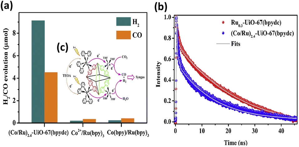 | ||
| Fig. 2 (a) Results of photocatalytic CO2 reduction under visible light illumination over (Co/Ru)2.4-UiO-67(bpydc) and the corresponding homogeneous counterparts. (b) Time-resolved PL spectra of (Co/Ru)2.4-UiO-67(bpydc) and Ru0.3-UiO-67(bpydc). Excitation and emission wavelength were 450 nm and 700 nm, respectively. (c) Proposed mechanism of interfacial charge transfer. Reproduced with permission from ref. 38. Copyright 2019, Elsevier. | ||
In the other study by Lin et al.,39 a FeNix BMOF composed of Prussian blue analogs (PBA) was synthesized to perform photocatalytic CO2 reduction. A trade-off effect from the synergy of the two metal sites was demonstrated to optimize the performance of CO2 reduction. The synergy is based on the distinct functionalities of Fe and Ni. Fe functions as a mediator to promote interfacial electron transfer, while Ni works as the active site to enable CO2 adsorption and reduction. Time-resolved PL data suggested enhanced charge transfer from photosensitizer to FeNix-PBA with increasing Fe content. By delicately adjusting the number of Fe and Ni sites in MOFs, a high CO yield along with a nearly 100% CO selectivity can be achieved.
3.2 Modification of organic linkers
By altering the composition of organic linkers, the bandgap of MOFs can be reduced to harvest an increased number of photons from the solar spectrum; this method was demonstrated to be an efficient strategy to tailor the photocatalytic properties of MOFs.46 This approach further gestates a conception involving the selection of specific substituent groups to modify the organic linkers of MOFs; thus, a capacity for visible light absorption is achieved. The successful substituent groups include –NH2, –OH, –SH, and –NO2.47–49 On the other hand, modification of organic linkers can tailor the band structure of MOFs to modulate interfacial charge transfer dynamics. This strategy also offers an effective route for optimizing the photocatalytic properties of MOFs. In Chen's study,40 two linkers, H2BDC-(SCH3)2 and H2BDC-(SOCH3)2, with different ratios were introduced to UiO-66 (Zr) through post-oxidation and direct synthesis, producing mixed-linker UiO-66-(SCH3)2-xh (x = 4, 9, 12, representing post-oxidation hours) and UiO-66-(SOCH3)x(SCH3)2−x, respectively. Pt was photodeposited on these MOFs to serve as a cocatalyst for photocatalytic H2 production (Fig. 3a). In Fig. 3b, the photocatalytic H2 production of the three mixed-linker Pt/UiO-66-(SCH3)2-xh and single-linker Pt/UiO-66-(SCH3)2 was compared. Pt/UiO-66-(SCH3)2-9h exhibited the maximum rate of H2 production, which was approximately 4.8 times that of Pt/UiO-66-(SCH3)2. On the other hand, compared to the single-linker UiO-66-(SOCH3) and UiO-66-(SCH3), UiO-66-(SOCH3)x(SCH3)2−x (x = 0.4, 0.6) exhibited markedly improved photocatalytic abilities (Fig. 3c). Notably, the percentage of BDC-(SOCH3)2 (23.9%) in UiO-66-(SOCH3)0.4(SCH3)1.6 is almost identical to that of BDC-(SOCH3)2 (24.4%) in UiO-66-(SCH3)2-9h. However, the photocatalytic H2 evolution rate of UiO-66-(SOCH3)0.4(SCH3)1.6 is half of that of UiO-66-(SCH3)2-9h. The performance difference between these two isostructural complexes further reveals the fundamentally different charge transfer dynamics involved.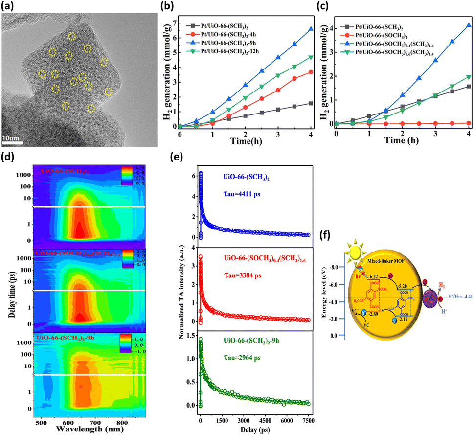 | ||
| Fig. 3 (a) HRTEM image of UiO-66-(SCH3)2-9h deposited with Pt. Results of photocatalytic H2 production under visible light illumination over (b) Pt/UiO-66-(SCH3)2 and Pt/UiO-66-(SCH3)2-xh, (c) Pt/UiO-66-(SOCH3)x(SCH3)2−x (x = 0, 0.4, 0.6, 2). (d) TA spectra at various probe delays and wavelengths for UiO-66-(SCH3)2, UiO-66-(SOCH3)0.4(SCH3)1.6, and UiO-66-(SCH3)2-9h. (e) Corresponding kinetic traces at 640 nm. The pump wavelength was 400 nm. (f) Proposed mechanism of interfacial charge transfer for UiO-66-(SCH3)2-xh. Reproduced with permission from ref. 40. Copyright 2021, American Chemical Society. | ||
This marked difference was ascribed to the distinctive molecular structure at the MOF surface. During the post-oxidation process for UiO-66-(SCH3)2-xh, the –SCH3 groups on the MOF surface were preferentially oxidized. The resulting –SOCH3 groups were concentrated on the surface of UiO-66-(SCH3)2-9h, which differs from the uniform distribution of –SOCH3 in the whole structure of UiO-66-(SOCH3)0.4(SCH3)1.6. The former localized molecular structure was feasible for reactant access and charge transfer. Hence, the H2 generation rate of UiO-66-(SCH3)2-9h was much higher than that of UiO-66-(SOCH3)0.4(SCH3)1.6, although they bear almost the same BDC-(SOCH3)2 ratio. To gain a deeper knowledge of the interfacial charge dynamics, fs-TA spectroscopy measurements were carried out on three representative samples. Fig. 3d shows the TA spectra for UiO-66-(SCH3)2, UiO-66-(SOCH3)0.4(SCH3)1.6, and UiO-66-(SCH3)2-9h as a function of probe delay time and wavelength. An intense excited state absorption band centered at approximately 640 nm was recorded. The kinetic traces at 640 nm were fitted with a multiexponential function, generating average lifetimes of 4411, 3384, and 2964 ps for UiO-66-(SCH3)2, UiO-66-(SOCH3)0.4(SCH3)1.6, and UiO-66-(SCH3)2-9h, respectively (Fig. 3e). Here, the shortest lifetime of UiO-66-(SCH3)2-9h indicated the fastest charge relaxation process results from the best charge separation efficiency, consistent with the trend in photocatalytic activity. A charge transfer mechanism based on type-II band alignment was considered for UiO-66-(SCH3)2-xh (Fig. 3f). In this mechanism, the two linkers were incorporated in the distinct region of the MOFs, forming a homojunction composed of MOF-BDC-(SOCH3)2 and MOF-BDC-(SCH3)2. Under light illumination, the photoexcited electrons were most likely transferred from the conduction band of MOF-BDC-(SOCH3)2 to that of MOF-BDC-(SCH3)2, whereas the photogenerated holes were transported in the opposite direction. The spatially separated electrons and holes can then participate in proton reduction and scavenger oxidation, respectively, leading to pronounced photocatalytic activity.
In the other study led by Wang et al.,41 the band structure was tuned by modifying MIL-125-NH2 with viologen molecules (RV2+); thus, the photocatalytic performance was improved. The morphology of MIL-125-RV2+ was essentially identical to that of MIL-125-NH2, revealing the structural integrity of the MOF skeleton upon modification (Fig. 4a). The band structures of MIL-125-NH2 and MIL-125-RV2+ were determined from Mott–Schottky measurements (Fig. 4b). Upon RV2+ modification, the conduction band level of MOFs was cathodically shifted by 0.23 V, which was beneficial for carrying out photocatalytic CO2 reduction to efficiently produce HCOOH. After 10 h of photocatalytic operation, the yield of HCOOH for MIL-125-RV2+ was 12.13 mmol, substantially higher than that of MIL-125-NH2 (7.31 mmol) (Fig. 4c). Time-resolved PL spectra further showed that the carrier lifetime of MIL-125-RV2+ was significantly longer than that of MIL-125-NH2. This observation indicated that the introduced RV2+ can coordinate interfacial charge transfer for MOFs to prolong the carrier lifetime (Fig. 4d). For MIL-125-NH2, the Ti4+ ions in the Ti-oxo clusters served as traps for photoexcited electrons, prohibiting their further participation in CO2 reduction. After RV2+ was introduced, the electron trapping at Ti4+ could be mitigated, which facilitated further relaxation of photoexcited electrons to the surface-adsorbed CO2. Under this situation, the photoexcited electrons of MIL-125-RV2+ had more opportunities to participate in CO2 reduction, leading to the enhanced performance of HCOOH production.
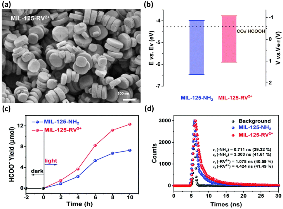 | ||
| Fig. 4 (a) SEM image of MIL-125-RV2+. (b) Band structure of MIL-125-NH2 and MIL-125-RV2+ concerning the redox potential of CO2/HCOOH at pH = 7. (c) Results of photocatalytic CO2 reduction under visible light illumination over MIL-125-NH2 and MIL-125-RV2+. (d) Time-resolved PL spectra of MIL-125-NH2 and MIL-125-RV2+. Reproduced with permission from ref. 41. Copyright 2022, Royal Society of Chemistry. | ||
3.3 Introduction of defects
Defects in MOFs have been characterized as local sites breaking the periodical arrangement of atoms in the crystalline framework. The missing organic linkers and missing metal clusters account for major defect types of MOFs. By introducing these point defects, the physical and chemical properties of MOFs can be tailored, providing another strategic maneuver to consolidate their utility in photocatalysis.50,51 The attributes of defective MOFs as photocatalysts include enriched active sites,52,53 optimized acidity and basicity,54,55 modified band structure56,57 and additional pore space.58,59 Zang et al. used a competitive coordination method to introduce ligand defects into Cu-triazolate frameworks (MET-Cu).42 During the synthesis of MET-Cu, adding N,N-diethylformamide can prohibit the coordination of Cu with triazole ligands. This would create abundant ligand vacancies (approximately 8%), producing an appreciable amount of unsaturated Cu sites that can function as active sites for photocatalytic reactions. In practice, the Cu centres of MET-Cu were coordinated with six triazole linkers, forming a well-defined octahedral morphology with a solid skeleton structure. After ligand vacancies were introduced, the defective MET-Cu (MET-Cu-D) contained an agglomeration of irregular small particles (Fig. 5a). For comparison purposes, the repaired sample (MET-Cu-R) was also prepared by passivating the linker vacancies of MET-Cu-D through recoordinating triazole linkers. The photocatalytic efficiency of H2 production for the three samples, i.e., MET-Cu, MET-Cu-D, and MET-Cu-R, was then explored. In addition to the use of MOFs, eosin Y (EY) as a photosensitizer and triethylamine (TEA) as a hole scavenger were employed to conduct photocatalytic H2 production. As shown in Fig. 5b, MET-Cu exhibited negligible activity because it did not possess open Cu centres that can serve as active sites for proton reduction. In contrast, MET-Cu-D displayed outstanding activity for H2 production, presumably due to the beneficial effect associated with the unsaturated Cu sites. In comparison with MET-Cu-D, the activity of MET-Cu-R was substantially reduced, suggesting that H2 production deteriorated due to the passivation of linker vacancies. This comparison further revealed the importance of introducing unsaturated Cu centres as active sites for facilitating photocatalytic reactions.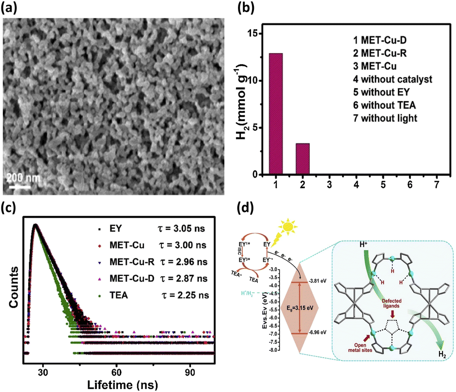 | ||
| Fig. 5 (a) SEM images of MET-Cu-D and MET-Cu (inset). (b) Results of photocatalytic H2 production under visible light illumination over the three samples under different conditions. (c) Time-resolved PL spectra of EY in the presence of the three samples. (d) Proposed mechanism of interfacial charge transfer for MET-Cu-D. Reproduced with permission from ref. 42. Copyright 2021, Elsevier. | ||
Time-resolved PL measurements were further conducted to study the influence of unsaturated Cu sites on the interfacial charge dynamics of MET-Cu. Fig. 5c shows the time-resolved PL spectra of EY in the presence of the three samples. For pure EY, the recorded PL lifetime was 3.05 ns. When MET-Cu, MET-Cu-R, and MET-Cu-D were dispersed in EY, the PL lifetime of EY was reduced to 3.00, 2.96, and 2.87 ns, respectively. This phenomenon indicated that the photoexcited electrons of EY were injected into MOFs, suppressing charge recombination for EY to reduce the PL lifetime. Significantly, the presence of defective MET-Cu-D caused the largest decrease in PL lifetime for EA, suggesting that the unsaturated Cu sites in MET-Cu-D can most effectively coordinate charge transfer dynamics for the injected electrons. Based on these observations, a plausible mechanism was proposed to account for the superior photocatalytic activity of MET-Cu-D, as shown in Fig. 5d. Under visible light illumination, EY was excited to generate singlet-state EY1*, followed by fast relaxation to form triplet-state EY3*. Subsequently, EY3* was reduced by the hole scavenger and formed EY−˙. Further injecting electrons into MET-Cu-D recovered the ground-state EY. In addition, the injected electrons presumably transferred to the unsaturated Cu centres, reacting with the adsorbed protons to evolve H2. For defective MET-Cu-D, the unsaturated Cu centres can function as active sites for H2 production and charge transfer mediators for the injected electrons. Due to the improved reaction kinetics and enhanced interfacial charge dynamics, MET-Cu-D exhibited superior photocatalytic activity towards H2 production.
He and coworkers used a similar approach to introduce missing linkers to UiO-66(Zr) by adding an acetic acid (HAc) modulator during the synthesis.43 The defective UiO-66(Zr) not only became visible light responsive but also possessed frustrated Lewis pairs, Zr3+–OH, which were conductive to photocatalytic CO2 reduction. As shown in the SEM images in Fig. 6a, noticeable morphological changes were observed in UiO-66(Zr) upon the introduction of missing ligands. Fig. 6b compares the photocatalytic efficiency of non-defective UiO-66-0 and that of four defective UiO-66-X (X = 2, 4, 6, 8) prepared with increasing amounts of HAc. For non-defective UiO-66-0, its large bandgap (3.92 eV) prohibited effective CO2 reduction under visible light illumination; as a result, nearly inactive performance was observed. For the four defective UiO-66-X, a volcano-type activity trend was found, in which UiO-66-6 showed the largest yield of CO. This result indicated that an optimal content of missing linkers generated the best photocatalytic activity for UiO-66-X.
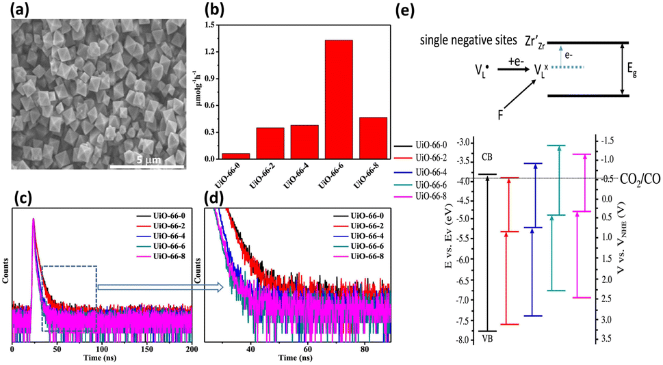 | ||
| Fig. 6 (a) SEM images of UiO-66-6 and UiO-66-0 (inset). (b) Results of CO production from photocatalytic CO2 production under visible light illumination over various UiO-66-X. (c and d) Time-resolved PL spectra of various UiO-66-X. (e) Proposed mechanism of the energetic state of missing ligands and derived band structure for various UiO-66-X (X = 0, 2, 4, 6, 8). Reproduced with permission from ref. 43. Copyright 2022, American Chemical Society. | ||
To determine what generates the optimal content of missing linkers, time-resolved PL analysis was performed to determine the carrier lifetime. As displayed in Fig. 6c and d, the four defective UiO-66-X samples all exhibited faster PL decay kinetics than that of nondefective UIO-66-0. The computed average lifetimes were 3.71, 3.34, 2.66, 2.12, and 2.29 ns for UIO-66-0, UIO-66-2, UIO-66-4, UIO-66-6, and UIO-66-8, respectively. This feature implied that missing linkers may improve charge separation efficiency by accepting photoexcited electrons from MOFs. Among the four defective MOFs, UiO-66-8 had the shortest PL lifetime, implying that the fastest carrier relaxation dynamics occur within UiO-66-8. The highest carrier mobility along with the most enhanced charge separation was therefore expected for UiO-66-8, which can account for the best CO yield observed. Note that a similar quantitative effect on interfacial charge dynamics has been widely reported in semiconductor heterostructure systems,17 which is decisive to the resultant photocatalytic performance. Fig. 6e depicts a possible mechanism that explains the role of missing ligands in mediating interfacial charge dynamics for defective UiO-66-X. Analogous to the creation of oxygen vacancies in oxide semiconductors, introducing missing ligands in MOFs generates a positively charged state termed  located within the bandgap. Upon bandgap excitation,
  can capture electrons and form neutral VLX. The electrons of VLX can then be excited to the conduction band by irradiation with energy lower than the bandgap, forming photoexcited electrons. Subsequently, the metal Zr centres captured the photoexcited electrons to form a single negative state Zr3+, in which the CO2 reduction reaction can readily occur. The additional absorption band observed for UiO-66-X in the longer wavelength region validated the above contentions. The band structure derived from the Mott–Schottky analysis further supported this argument. After missing ligands were introduced, the whole band structure of MOFs was lifted to a more cathodic level, which can increase the reducing power of the photoexcited electrons to facilitate the CO2 reduction reaction.
4. Incorporation of heterojunction
The incorporation of heterojunctions that combine the desirable properties of individual constituents into an integrated whole was a significant step in achieving advanced photocatalysis for semiconductor nanostructures.60,61 Four types of heterojunctions have been incorporated to design sophisticated photocatalysts,17,60–62 including metal–semiconductor, graphene–semiconductor, semiconductor–semiconductor, and Z-scheme (or S-scheme) heterojunctions. Metal–semiconductor heterojunctions are characteristic of pronounced charge separation and peculiar plasmonic effect. Metal can function as electron acceptors, prohibiting charge recombination to improve charge separation.63–67 Some metals exhibit localized surface plasmon resonance (LSPR),68–71 amplifying light absorption and thus, increasing photocatalytic activity. However, only certain wavelengths can be harnessed due to the narrow bandwidth of LSPR. Semiconductor–semiconductor heterojunctions comprise either a type-I,72 a type-II73–78 or a p–n interface.79 Interfacial charge transfer can be manipulated to allow effective carrier utilization, thereby increasing the photocatalytic performance. Merging semiconductors with divergent bandgaps enables the capture of a broader light spectrum. Nevertheless, the band edges must align properly for efficient charge transfer, limiting the available semiconductor combinations. The charge carriers may also be trapped at the interface, leading to reduced photocatalytic efficiency.Graphene–semiconductor heterojunctions function on principles similar to metal–semiconductor heterojunctions.80–83 Because of the superior electron mobility, graphene acts as an electron acceptor for semiconductors, thereby reducing charge recombination. Furthermore, graphene provides a protective layer against the photocorrosion of semiconductors, proven to be a solution to resolve instability issues. However, ensuring a robust interface between graphene and semiconductors is challenging. Excessive graphene layers may obstruct light penetration to the underlying semiconductor, compromising overall photocatalytic efficiency. Z-scheme heterojunctions display a vectorial charge transfer mechanism mimicking natural photosynthetic processes.84,85 The separate charge carriers possess substantially high redox powers to ensure superior activity. Z-scheme heterojunctions can also incorporate semiconductors with diverse bandgaps for expanded light absorption. However, creating an efficient Z-scheme system necessitates a comprehensive understanding of the band structure of the semiconductor. Occasionally, an additional electron mediator, composed of metals86–88 or graphene,89 is indispensable to realize vectorial charge transfer, complicating the configuration.
The approach of heterojunction incorporation has also been widely adopted to construct sophisticated photocatalytic systems based on MOFs. Compared with traditional semiconductor-based heterojunctions, MOF-based heterojunctions exhibit more favorable synergistic features by virtue of the easily tailorable material properties, which are generated by engineering metal clusters and organic ligands.90,91 Several advantages associated with photocatalytic applications, including extended light harvesting, pronounced charge separation, enriched active sites and improved photostability, can be obtained by incorporating heterojunctions in MOFs. Successful examples involve semiconductor coupling,92–96 metal confinement,97,98 the introduction of another MOF,99,100 and the addition of graphene.101 The promise of heterojunction incorporation for MOFs in photocatalytic applications from the perspective of interfacial charge dynamics will be highlighted in this section.
4.1 Semiconductor coupling
Compared with semiconductor nanostructures, MOFs have received more fundamental and technological interest in photocatalysis due to their high tailorability and versatility in property design. By coupling with a semiconductor possessing suitable band alignment, the photocatalytic properties of MOF-based heterojunctions can be substantially improved. In Xu's study,92 a stable MOF, UiO-66, was employed as a support to deposit CdS nanoparticles in a controllable content (from 10 to 40 wt%), forming CdS/UiO-66 heterojunctions. When the CdS content was 10 wt%, UiO-66 was found to induce uniform growth of small CdS nanoparticles (Fig. 7a and b). Further increasing the CdS content to 20 and 40 wt% led to significant aggregation of the deposited CdS. Fig. 7c compares the photocatalytic activity of H2 production among relevant samples under visible light illumination. Pure UiO-66 did not produce H2 because of its large bandgap (4.1 eV). Pure CdS, on the other hand, produced a small amount of H2 due to its inadequate capability as a single material. For CdS/UiO-66, the amount of H2 produced was largely increased, suggesting that the interplay between UiO-66 and CdS can promote photocatalytic performance. Among the three CdS/UiO-66 samples, the sample with 10 wt% CdS showed the highest H2 production activity, exceeding eight times the performance of pure CdS. The decreased activity for CdS/UiO-66 with CdS contents of 20 and 40 wt% was attributed to the significant aggregation of the decorated CdS, which may reduce the exposed active sites to deteriorate the photocatalytic activity.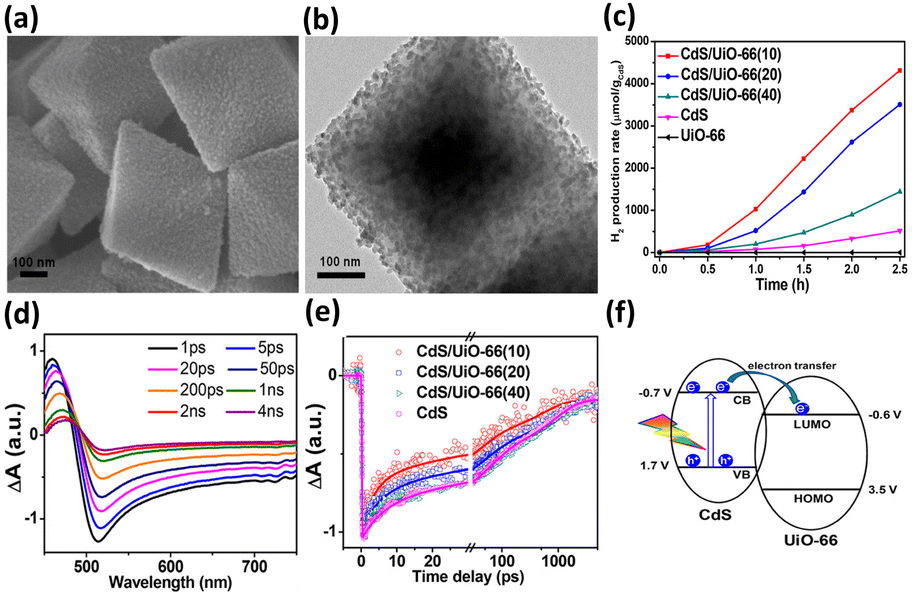 | ||
| Fig. 7 (a) SEM and (b) TEM images of CdS/UiO-66(10). (c) Results of photocatalytic H2 production under visible light illumination over five relevant samples. TA spectra of (d) pure CdS. (e) Comparison of kinetics profiles probed at 650 nm among pure CdS and the three CdS/UiO-66. (f) Proposed mechanism of interfacial charge transfer for CdS/UiO-66. Reproduced with permission from ref. 92. Copyright 2019, American Chemical Society. | ||
To examine the interfacial charge dynamics for CdS/UiO-66 heterojunctions, fs-TA spectroscopic measurements were conducted by pumping the samples at 400 nm and probing them from 450 to 750 nm. As displayed in Fig. 7d, pure CdS showed three noticeable features at 460 nm, 500 nm, and the region beyond 600 nm. The negative absorption band at 500 nm was assigned to the 1S exciton bleach of CdS resulting from the state filling of the 1S(e) level at the conduction band.102 The positive absorption band at 460 nm was associated with the photoinduced absorption of the 1S exciton.103 The broad bleaching band at approximately 650 nm was related to the signal of photoexcited electrons, which resulted from accelerated quenching in the presence of an electron scavenger. The kinetics of the bleach recovery at 650 nm were further examined to investigate the fate of the photoexcited electrons. As compared in Fig. 7e, the three CdS/UiO-66 samples exhibited much faster bleach recovery than that of pure CdS, suggesting the prevalence of an additional electron relaxation pathway at the CdS/UiO-66 heterojunctions. Mott–Schottky analytical results further revealed a type-II band alignment for CdS/UiO-66 (Fig. 7f). Under this situation, the photoexcited electrons of CdS preferentially transferred to UiO-66, thereby accelerating the bleach recovery processes of electrons probed at 650 nm. Significantly, the trend in bleach recovery kinetics for the three CdS/UiO-66 samples was consistent with the variation in the corresponding photocatalytic activity, i.e., the sample with the fastest bleach recovery kinetics had the highest photocatalytic activity. This consistency illustrated that UiO-66 can facilitate charge carrier separation for CdS to optimize H2 production activity. The findings from this work also highlight the unique features of MOFs in promoting the structural dispersion of the coupled semiconductor, securing surface active sites to ensure utility in photocatalysis. A similar approach has been adopted to couple UiO-66 with g-C3N4 for enhanced photocatalytic H2 production.95 The shortened PL lifetime of heterojunction reflected efficient photoexcited electron transfer from g-C3N4 to UiO-66 through a type-II pathway. The separated electrons can readily participate in the H2 production reaction.
The location of the coupled semiconductors at the specific site of MOFs also significantly impacted the effectiveness of interfacial charge transfer for MOF/semiconductor heterojunctions, which is an adoptable route to optimize photocatalytic efficiency. In Ghosh's study, CdS was introduced to Zr4+-based MOF-808 at two distinct locations, i.e., inside the cavities of MOF-808 (denoted as CdS4@MOF-808) and outside the surface of MOF-808 (denoted as CdS/MOF-808-cys), creating two analogous heterojunctions.93 As displayed in Fig. 8a and b, the TME analytical results confirmed the microstructural features of CdS4@MOF-808 and CdS/MOF-808-cys, in which the confinement of CdS nanoparticles inside the pores of MOF-080 and the presence of CdS nanoparticles on the external surface of MOF-808 can be identified. Note that the content of the coupled CdS was fixed so that photocatalytic H2 production could be equitably compared. As revealed in Fig. 8c, CdS4@MOF-808 had a substantially higher H2 yield than CdS/MOF-808-cys, suggesting that introducing CdS inside the cavities of MOF-808 can achieve better photocatalytic performance due to the confinement effect. To understand this confinement effect from the charge dynamics point of view, TA measurements were conducted by pumping the samples at 400 nm and probing them from 420 to 650 nm. The two heterojunction samples share similar spectral features associated with CdS, i.e., one positive absorption band below 440 nm, one primary negative bleach band at approximately 480 nm, and another broad negative bleach band from 500 to 650 nm. The bleach recovery at approximately 480 nm reflected the depletion of the photoexcited electrons at the conduction band of CdS, which was further traced in Fig. 8d to interrogate the fate of the photoexcited electrons. The kinetics profile of CdS/MOF-808-cys comprised three time constants of 0.83 ps (33%), 21 ps (53%), and 3.12 ns (14%). The two fast recovery components were related to the trapping of the photoexcited electrons at the defect states, in which the relatively slow component was associated with the recombination of the photoexcited electrons with the trapped holes. Compared with CdS/MOF-808-cys, CdS4@MOF-808 displayed faster kinetics of bleach recovery, showing three time constants of 0.22 ps (44%), 13.2 ps (31%), and 384 ps (25%). This outcome suggested that the photoexcited electrons of CdS can be more easily delocalized in CdS4@MOF-808. The separated photoexcited electrons can then readily participate in photocatalytic H2 production. As shown in Fig. 8e, density functional theory (DFT) calculations revealed an interfacial electron transfer pathway from CdS to the Zr4+ sites of MOF-808. For CdS4@MOF-808, because CdS was confined in close proximity to the Zr4+ sites of MOF-808, a shorter electron transfer path from CdS to MOF-808 was considered. This spatial confinement may promote more effective charge separation and increase the photocatalytic activity of CdS4@MOF-808 as observed.
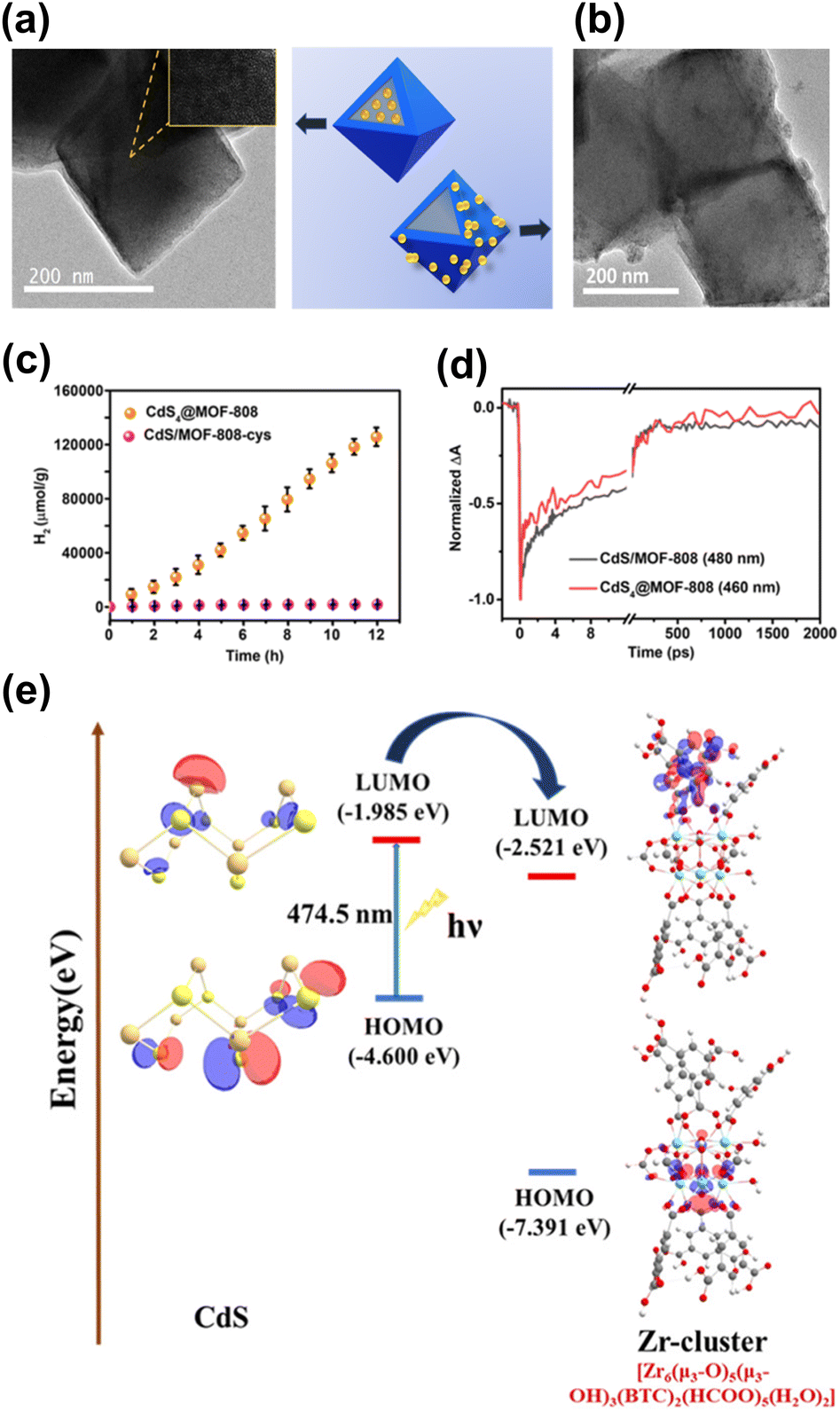 | ||
| Fig. 8 TEM images of (a) CdS4@MOF-808, (b) CdS/MOF-808-cys. (c) Results of photocatalytic H2 production under visible light illumination over the two samples. (d) Comparison of kinetics profiles probed around 480 nm between the two samples. (e) Proposed mechanism of interfacial charge transfer for CdS and MOF-808. Reproduced with permission from ref. 93. Copyright 2019, Royal Society of Chemistry. | ||
In addition to enhancing charge separation, MOFs can improve photostability for coupled semiconductors, which is an effective strategy to increase the durability of those suffering from photocorrosion issues. In Deng's study, Cu3(BTC)2 was employed as the MOF model to protect Cu2O photocathodes from photocorrosion during the CO2 reduction process.94 As displayed in Fig. 9a and b, Cu3(BTC)2 with a protruding columnar morphology was grown on the surface of the Cu2O thin films. The performance of Cu3(BTC)2/Cu2O in photoelectrochemical (PEC) CO2 reduction under visible light illumination was examined. Fig. 9c compares the production yield of CO between Cu3(BTC)2/Cu2O and pristine Cu2O under different conditions. In darkness, Cu3(BTC)2/Cu2O showed a CO yield that was 2 times higher than that of pristine Cu2O. This result signified that the Cu atoms of the deposited Cu3(BTC)2 supplied incremental active sites for facilitating CO production from CO2 reduction. Under visible light illumination, Cu3(BTC)2/Cu2O exhibited a threefold increase in CO yield relative to pristine Cu2O. The increasing activity enhancement suggested that the deposited Cu3(BTC)2 promoted effective charge separation for Cu2O by accepting the photoelectrons from Cu2O. The delocalized electrons can then readily participate in CO2 reduction. During PEC operation, pristine Cu2O tended to undergo oxidative photocorrosion, which can consume photoexcited electrons to compromise the effectiveness of CO2 reduction. In Fig. 9d, the unstable, declining photocurrent generation of pristine Cu2O was characteristic of serious photocorrosion. Cu3(BTC)2/Cu2O, however, exhibited stable and constant photocurrent generation, suggesting that the deposited Cu3(BTC)2 can protect the underlying Cu2O from photocorrosion. Due to this protection, both the faradaic efficiency and solar-to-CO2 conversion efficiency were substantially enhanced.
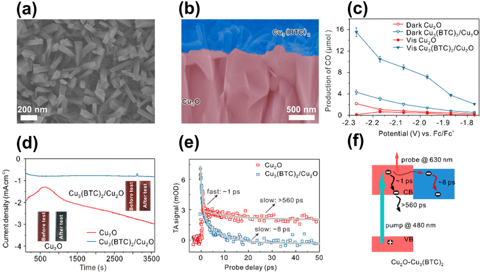 | ||
| Fig. 9 (a) Top-view and (b) cross-section SEM images of Cu3(BTC)2/Cu2O. (c) Results of CO production from PEC CO2 production under visible light illumination over pristine Cu2O and Cu3(BTC)2/Cu2O. (d) Corresponding photocurrent generation for an extended period. (e) Comparison of kinetics profiles probed at 630 nm between pristine Cu2O and Cu3(BTC)2/Cu2O. (f) Proposed mechanism of interfacial charge transfer for Cu3(BTC)2/Cu2O. Reproduced with permission from ref. 94. Copyright 2018, Wiley. | ||
A type-II band alignment was also considered for Cu3(BTC)2/Cu2O heterojunctions. Under light illumination, the photoexcited electrons of Cu2O preferentially transferred to Cu3(BTC)2 and participated in CO2 reduction. To probe this process, TA measurements were conducted by pumping the samples at 480 nm. Fig. 9e compares the kinetics profiles of the photoinduced absorption decay between pristine Cu2O and Cu3(BTC)2/Cu2O. Pristine Cu2O showed biexponential decay kinetics with two lifetime constants of 1 ps and 560 ps. As depicted in Fig. 9f, the fast decay was assigned to the electron relaxation within the conduction band of Cu2O, whereas the slow decay was ascribed to the subsequent electron–hole recombination. Upon the deposition of Cu3(BTC)2, only the fast decay component with a lifetime of 8 ps was observed. Because Cu3(BTC)2 attracted photoexcited electrons from Cu2O, the intrinsically slow electron–hole recombination was prohibited. This interfacial electron can accelerate excited state deactivation, resulting in the quicker kinetics of photoinduced absorption decay observed for Cu3(BTC)2/Cu2O. This study revealed that Cu3(BTC)2 plays multiple roles in enhancing the CO2 reduction performance of Cu2O photocathodes, including roles as a photocorrosion inhibitor, active site provider, and charge separation enhancer.
One the other hand, the Z-scheme mechanism can be attained by coupling MOFs with a semiconductor that can induce vectorial charge transfer. Kong's group reported the synthesis of UiO-66-(COOH)2/ZnIn2S4 hybrid photocatalysts for applications in H2 production and Cr5+ reduction.96 Because of the band alignment at the interface, the photoexcited electrons of UiO-66-(COOH)2 were recombined with the photogenerated holes of ZnIn2S4. This vectorial charge transfer led to the accumulation of photoexcited electrons at ZnIn2S4 and the concentration of photogenerated holes at UiO-66-(COOH)2, realizing the Z-scheme mechanism. The observed prolonged PL lifetime for UiO-66-(COOH)2/ZnIn2S4 suggested the prevalence of charge carrier recombination at the interface. By virtue of the Z-scheme mechanism, UiO-66-(COOH)2/ZnIn2S4 photocatalysts possessed enhanced reducing and oxidizing powers, thus exhibiting superior activity toward H2 reduction and Cr5+ reduction.
4.2 Metal confinement
The profitable features of noble metal nanoparticles, including their unique electronic structure and peculiar optical properties, have been utilized in semiconductor photocatalysis.17,60,61 It is therefore not surprising to see the entry of metal nanoparticles in the MOF-based photocatalytic systems.97,98 Due to the porous nature and robust structure of MOFs, they are ideal supports for metal nanoparticles. In particular, the uniform nanopores in MOFs can provide confined environments to enable size control over the target metals and can simultaneously guarantee that the reactant molecules are accessible to the active metal sites. This feature is especially important for maximizing the utilization of surface active sites in metals since metal nanoclusters or even metal single atoms can be incorporated. Furthermore, organic ligands can function as anchors to stabilize tethered metals, ensuring their long-term effectiveness in heterogeneous catalysis. Jiang's group utilized the confined cavities of MOFs to enable the intercalation of single Pt atoms.97 An Al-based porphyrinic MOF, termed Al-TCPP, which has four pyrrolic N sites, was employed. As Fig. 10a shows, because of the strong interaction with the pyrrolic N atoms, single Pt atoms can be stabilized in the square-planar cavities of the porphyrin struts in Al-TCPP. The resultant single Pt atom-loaded Al-TCPP (denoted as Al-TCPP-0.1Pt, Pt content = 0.1 wt%) showed a major Pt size distribution between 0.1 and 0.2 nm. On the other hand, Pt nanoparticles 3 nm in size were prepared in advance and introduced to the external surface of Al-TCPP. This Pt-mixed Al-TCPP (denoted as Al-TCPP-PtNPs) served as a control sample so that the performance in photocatalytic H2 production could be compared. The comparative results showed that pristine Al-TCPP was nearly inactive towards H2 production under visible light illumination, which was ascribable to the pronounced charge recombination. Al-TCPP-0.1Pt and Al-TCPP-PtNPs were considerably active due to the enhanced charge separation rendered by Pt. Noticeably, Al-TCPP-0.1Pt exhibited a turnover frequency that was 30 times higher than that of Al-TCPP-PtNPs, indicating that loading Pt in the cavities of Al-TCPP was more effective in promoting photocatalytic performance.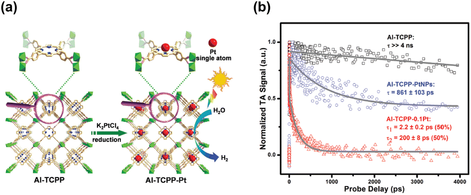 | ||
| Fig. 10 (a) Schematic illustration for the intercalation of single Pt atoms in the confined cavity of Al-TCPP. (b) Comparison of kinetics profiles probed at 540 nm among the three samples. Reproduced with permission from ref. 97. Copyright 2020, Royal Society of Chemistry. | ||
To gain more insights into the cause, TA analysis was conducted to investigate the interfacial charge carrier dynamics. The samples were pumped at 400 nm and probed between 520 and 640 nm, a spectral region associated with the trap states of photoexcited electrons. Fig. 10c shows the resultant kinetics traces for the photoinduced absorption signals at 540 nm. Pristine Al-TCPP featured a slow decay process with a lifetime component longer than 4 ns. This feature suggested that the photoexcited electrons were stably trapped and hardly utilized for H2 production. An evident acceleration of decay kinetics was observed for Al-TCPP-PtNPs, showing a dominant lifetime of 861 ± 103 ps. The acceleration in kinetics occurred because an additional electron transfer pathway from Al-TCPP to Pt nanoparticles emerged. This may accelerate the removal of the trapped electrons and allow them to participate in H2 production. As a result, Al-TCPP-PtNPs exhibited noticeable photocatalytic activity. The acceleration of decay kinetics became more pronounced for Al-TCPP-0.1Pt, showing two lifetime components of 2.2 ± 0.2 ps (50%) and 200 ± 8 ps (50%). This outcome signified that loading a small content of single Pt atoms in the cavities of Al-TCPP can maximize the effectiveness of interfacial charge transfer, leading to very enhanced photocatalytic activity, as observed. This study delivers an innovative yet reliable approach for the stabilization of single metal atoms by exploiting the microstructural characteristics of MOFs, which provides new opportunities for using MOF-based heterojunctions for advanced photocatalytic applications.
The benefits of loading metals precisely in the cavities of MOFs in photocatalysis were highlighted in Guo's study.98 As illustrated in Fig. 11a, the following scenarios for the incorporation of Pt nanoparticles in Zr-MOF and NH2-UiO-68 were systematically compared: (A) Pt was embedded outside the cavities of NH2-UiO-68 (denoted as Pt/NH2-UiO-68); (B and C) Pt was embedded inside the cavities of NH2-UiO-68 (denoted as Pt@NH2-UiO-68); and (D) Pt was embedded outside and inside the cavities of NH2-UiO-68 (denoted as Pt–NH2-UiO-68). These Pt-loaded NH2-UiO-68 samples were used as photocatalysts to perform CO2 reduction under visible light illumination. Fig. 11b shows the comparative results obtained for CO yields, from which several important points can be summarized. First, the presence of Pt enhanced the CO production yield of NH2-UiO-68 regardless of the scenario of Pt incorporation. This outcome revealed the necessity of incorporating metals to enhance the photocatalytic activity of MOFs. Second, among all the Pt-incorporated NH2-UiO-68 samples, Pt(2)@NH2-UiO-68 (Pt content = 2 wt%) generated the highest CO yield, approximately three and two times the performance of Pt(2)/NH2-UiO-68 and Pt(4)–NH2–UiO-68, respectively. The performance of Pt(2)@NH2-UiO-68 was also better than that of Pt-mixed NH2-UiO-68 (denoted as Pt(2) + NH2-UiO-68). The superior activity of Pt(2)@NH2-UiO-68 disclosed the advantageous feature of loading metals inside the MOFs for achieving superb photocatalytic performance. This feature was further examined by looking into the interfacial charge dynamics of the samples using time-resolved PL spectroscopy. As shown in Fig. 11c, the PL lifetime of NH2-UiO-68 was largely reduced after Pt was incorporated. The occurrence of photoexcited electron transfer from NH2-UiO-68 to Pt accounted for the observed reduced lifetime, which can explain the enhanced photocatalytic activity. Among all the Pt-incorporated NH2-UiO-68 samples, Pt(2)@NH2-UiO-68 displayed the shortest PL lifetime. This result suggested that the effectiveness of interfacial electron transfer can be greatly enhanced by loading Pt inside NH2-UiO-68. In this situation, the incorporated Pt was in close contact with NH2-UiO-68, which can facilitate interfacial electron transfer to maximize the photocatalytic performance. Another important point noticed from Fig. 11b was the performance comparison with the analogous MOF with shorter linkers, NH2-UiO-66. Inferior performance of CO production occurred because shorter organic linkers endow MOFs with a weaker CO2 adsorption capacity. This outcome also emphasized the significance of engineering organic ligands to tailor the material properties of MOFs to optimize photocatalytic efficiency.
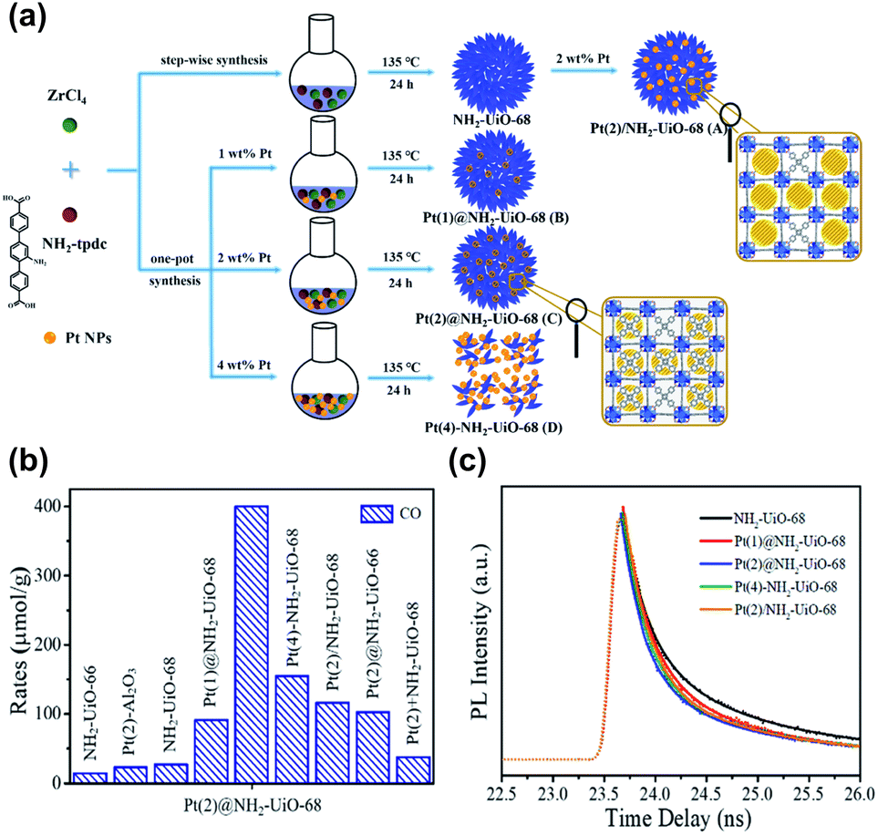 | ||
| Fig. 11 (a) Schematic illustration for three distinct scenarios of incorporating Pt nanoparticles in NH2-UiO-68. (b) Results of CO production from photocatalytic CO2 reduction under visible light illumination over relevant samples. (c) Time-resolved PL spectra of pristine NH2-UiO-68 and various Pt-incorporated NH2-UiO-68. Excitation and emission wavelength were 360 nm and 475 nm, respectively. Reproduced with permission from ref. 98. Copyright 2016, Wiley. | ||
4.3 Another MOF introduction
Due to the presence of independent active sites, merging two MOFs into a whole may generate multiple synergies and diversified configurations that can provide a robust and flexible foundation for photocatalysis.99,100 For instance, the mixed metallic active sites in the merged MOFs can work together to achieve intermediate interaction strengths with reactant molecules, improving activity and selectivity. The inclusion of multiple types of organic ligands may also equip the merged MOFs with multifunctional surface moieties, increasing their adaptability in complex reaction environments. One MOF has been modified with the other MOF to expand the heterojunction family for advanced photocatalysis. In Huang's study, a hierarchical core@shell MOF@MOF heterojunction was proposed by depositing UiO-67-NH2 on the first-grown PCN-222-Ni.99 Based on the results of radial spin-trapping experiments, a Z-scheme band alignment was considered for the resulting core@shell PCN-222-Ni@UiO-67-NH2 heterojunctions (denoted as P@U). As displayed in Fig. 12a, under light illumination, the photoexcited electrons of UiO-67-NH2 recombined with the photogenerated holes of PCN-222-Ni. This would lead to the accumulation of photoexcited electrons at PCN-222-Ni, which had a higher conduction band level, and the concentration of photogenerated holes at UiO-67-NH2, which had a low valence band level. Because the electrons and holes were situated at energetic levels with high redox potentials, remarkable photocatalytic efficiency was expected for P@U. Fig. 12b and c summarize the results obtained for photocatalytic CO2 reduction. Compared with pure PCN-222-Ni and pure UiO-67-NH2, P@U displayed substantially higher yields of liquid (HCOOH) and gaseous products (CO, CH4). Further insights into the interfacial charge dynamics at the Z-scheme heterojunction of P@U can be acquired from the time-resolved PL data in Fig. 12d. Both PCN-222-Ni and UiO-67-NH2 components exhibited well-defined PL emission bands in response to pronounced electron–hole recombination, showing PL lifetimes of 1.81 and 1.77 ns, respectively. Upon the formation of the core@shell heterojunction, the PL emission was largely quenched along with a greatly reduced lifetime of 0.76 ns. These data supported the Z-scheme charge transfer mechanism, which further accounted for the observed superior photocatalytic performance of P@U.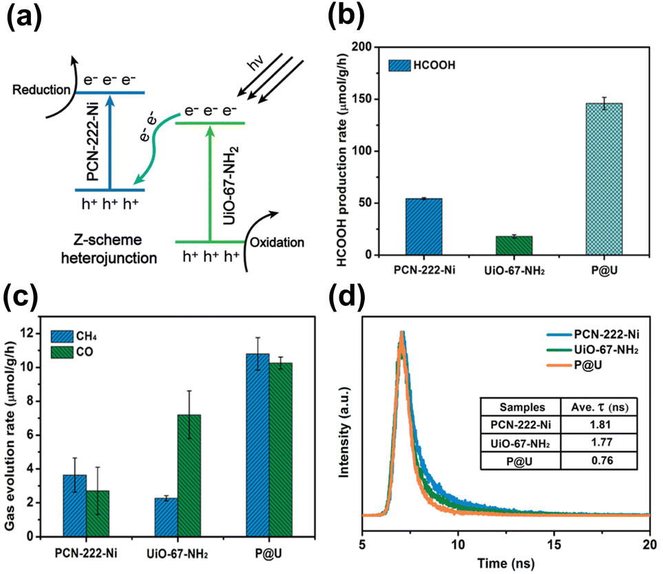 | ||
| Fig. 12 (a) Proposed Z-scheme charge transfer mechanism for P@U. Results of (b) HCOOH, (c) CO and CH4 production from photocatalytic CO2 production under visible light illumination over relevant samples. (d) Time-resolved PL spectra of relevant samples. The excitation wavelength was 375 nm; emission wavelength was 475, 500, and 480 nm for pure PCN-222-Ni, pure UiO-67-NH2, and P@U, respectively. Reproduced with permission from ref. 99. Copyright 2022, Royal Society of Chemistry. | ||
On top of the enhanced activity, the selectivity of a target product can also be improved by employing core@shell MOF@MOF heterojunctions. Shi's group reported the synthesis of core@shell Fe-MOF@Ni-MOF heterojunctions (denoted as Fe/Ni-TX, where X = reaction temperature in °C) for applications in photocatalytic CO2 reduction.100 Note that the photocatalytic experiments were carried out by adding [Ru(bpy)3]2+ as a photosensitizer, triethanolamine (TEOA) as a sacrificial reagent and acetonitrile as a solubility enhancer of CO2. Fig. 13a and b summarize the comparative results. Under optimal synthetic conditions, the core@shell heterojunction, i.e., Fe/Ni-T120, exhibited a considerably higher yield of CO than that of its pure counterparts. This superiority was ascribed to the prevalence of interfacial charge transfer and effective charge separation, as derived from the much faster PL decay kinetics observed in Fig. 13c. Much significantly, Fe/Ni-T120 achieved a remarkable 92.1% selectivity of CO from CO2 reduction. This value surpassed the performance of most state-of-the-art photocatalysts reported, highlighting the capability of core@shell MOF@MOF heterojunctions with bimetallic active sites for mediating the reaction pathways of CO2 reduction. Fig. 13d shows a plausible mechanism that accounts for CO production from photocatalytic CO2 reduction over Fe/Ni-T120. Under visible light illumination, Fe/Ni-T120 can be sensitized by [Ru(bpy)3]2+ and excited by incident light, producing photoexcited electrons to manage the production of CO. As a sacrificial reagent, TEOA can reduce [Ru(bpy)3]3+ to recover its original state. Meanwhile, H2O can consume photogenerated holes to complete the whole reaction. This study features an innovative bimetallic organic skeleton for core@shell MOF@MOF heterojunctions, in which the two metals can work together to manage CO2 reduction.
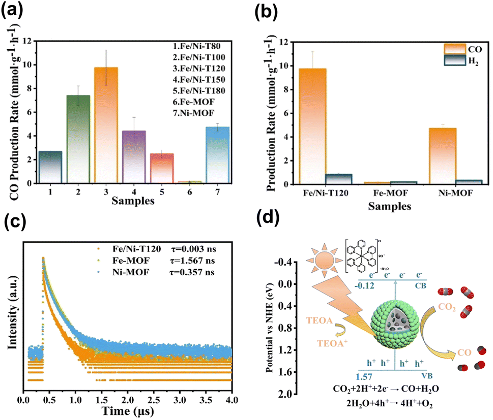 | ||
| Fig. 13 (a and b) Results of CO and H2 production from photocatalytic CO2 production under visible light illumination over relevant samples. (c) Time-resolved PL spectra of relevant samples. (d) Proposed mechanism of photocatalytic CO2 reduction on Fe/Ni-T120. Reproduced with permission from ref. 100. Copyright 2012, American Chemical Society. | ||
5. COFs as an analogue
The photocatalytic activity of MOFs is accentuated by their unique porous structures with various dimensions. However, most of these structures are unstable in water or solvents with highly coordinating reagents, which prevents the repeated use of MOFs as photocatalysts.104–106 COF-based photocatalysts are potentially preferable to MOF-based photocatalysts. As an analog of MOFs, COFs share many similar characteristics with MOFs. The most significant difference between COFs and MOFs is how their two-dimensional (2D) or three-dimensional (3D) porous frameworks are constructed. MOFs are connected by coordination bonds between metal ions and coordinative organic linkers. In contrast, COFs are connected by covalent bonds between rigid organic motifs (knots) and linkers composed of light elements (e.g., B, C, N, and O). As covalent bonds are more robust than coordination bonds, COFs exhibit better chemical and thermal stability than MOFs. Photoactive units in COFs can be installed into robust frameworks through strong covalent bonds, suppressing their photocorrosion and enabling long-term use.107,108 In addition, the mass density of COFs is generally lower than that of MOFs due to the absence of metal ions. Therefore, COFs are expected to exhibit greater adsorption capacity than that of MOFs.109,110The first synthesis of COFs111 was ten years after that of MOFs.112 Therefore, compared with MOF-based photocatalysts, the research field of COF-based photocatalysts is in the early stage. On the other hand, various photocatalytic reactions, such as water splitting, CO2 reductions, photodegradation of organic dyes, and photocatalytic transformation of organic compounds, achieved by MOF-based photocatalysts can also be realized by COF-based photocatalysts, indicating that COFs photocatalysts are promising photocatalysts.18 In this section, we will briefly introduce COF-based photocatalysts as an analog of MOF-based photocatalysts. The main focus will be on how the chemical structures of COFs affect their photocatalytic activities because their chemical structures are strongly related to their electronic properties, such as bandgap and charge carrier mobility.
5.1 π-Conjugated structures
In general, a narrow bandgap improves the efficiency of solar energy harvesting, which enhances photocatalytic activities. One approach used to manipulate the bandgap of COFs is designing extended π-conjugated moieties in-plane and in the layer stacking direction. Through extended π-conjugated moieties, photoexcited charge carriers can be transported through the whole COF network for delocalization, which not only narrows the bandgap of COFs but also reduces the possibility of charge carrier recombination. Upon the extension of the π-conjugated moieties, the absorption range of organic molecules with π-conjugated moieties in their skeletons can be shifted to longer wavelengths. To design fully sp2-carbon-linked COFs, poly(p-phenylene) linkers are often chosen first. The optical properties of COFs and their pore size are easily controlled by changing the number of repeating units of poly(p-phenylene) linkers. Zhang's group synthesized fully sp2-carbon-linked COFs that contain polyphenylene linkers with different lengths and investigated how the length of the polyphenylene linkers affects the optical properties and photocatalytic performance.113,114 They demonstrated that an increase in the repeating units of poly(p-phenylene) linkers was found to enhance the light-harvesting ability of the synthesized COFs, which increased the activity for photocatalytic H2 production under visible light irradiation. However, increasing the length of poly(p-phenylene) linkers installed into fully sp2-carbon-linked COFs does not always improve photocatalytic performance. Meier and coworkers prepared covalent triazine-based frameworks composed of triazine rings as knots and different poly(p-phenylene) spacers as linkers via acid-catalyzed cyclotrimerization (CTF-n, n = 1–4).115Fig. 14a shows the corresponding molecular structure of CTF-n. The light absorption characteristics of CTF-n can be readily tuned by changing the phenylene units. As displayed in Fig. 14b, the bandgap of CTF-n gradually decreased from 2.95 to 2.48 eV as the number of repeating phenylene units increased from 1 to 4, suggesting that the light-harvesting efficiency improved. On the other hand, DFT calculations showed that the redox powers of CTF-n also varied with phenylene units. As Fig. 14c summarizes, the oxidizing power of CTF-n decreased as the phenylene units increased, while the reducing power of CTF-n remained nearly unchanged. The compromise between improved light harvesting and decreased oxidizing power led to the highest photocatalytic activity of H2 production observed for CTF-2 (Fig. 14d). These studies highlight how the photocatalytic activity of COFs can be controlled by tuning the structural features.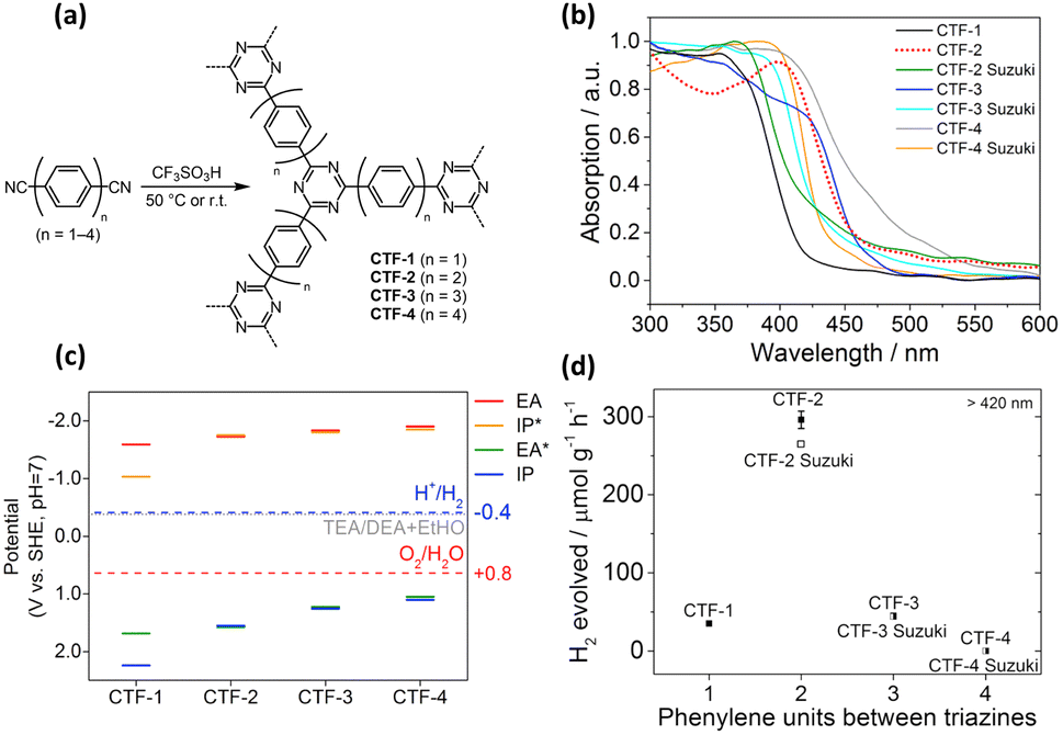 | ||
| Fig. 14 (a) Synthesis of CTF-n via acid-catalyzed cyclotrimerization. (b) Corresponding absorption spectra. (c) Calculated reducing (EA, IP*) and oxidizing potentials (IP, EA*) for CTF-3. (d) Relationship between H2 yield and number of repeating phenylene units for CTF-n. Reproduced with permission from ref. 115. Copyright 2017, Elsevier. | ||
5.2 Donor–acceptor (D–A) units
Another approach used to tune the bandgap of COFs is installing D–A components into their frameworks. The introduced donor and acceptor units strongly interact with each other, which results in the hybridization of the energy levels of the donor and acceptor units to form the HOMO and the LUMO for the D–A components. As illustrated in Fig. 15a, the new hybridized HOMO has a higher energy level than the donor units, whereas the new hybridized LUMO has a lower energy level than the acceptor units, which narrows the bandgap. In addition, D–A components facilitate electron transfer from donor units to acceptor units, which reduces the recombination of photoexcited electron–hole pairs. Wang and coworkers demonstrated that an sp2-carbon-based COF with D–A components showed a higher photocatalytic H2 production activity than that of its analogs without D–A components.116 Three vinylene-linked two-dimensional COFs (BTH-1, BTH-2, and BTH-3) containing benzobisthiazole (BTH) units were synthesized using different C3 symmetrical aldehydes (TA, TP, and TS) (Fig. 15b). Among the three synthesized COFs, BTH-3 composed of BTH and TS showed the narrowest bandgap (1.42 eV) because the donor–acceptor interactions between the electron-donating benzotrithiophene units and the cyano-vinylene linkages connecting the electron-deficient benzobisthiazole units were strong (Fig. 15c). The results obtained from photocurrent measurements and electrochemical impedance spectroscopy suggested that BTH-3 exhibited better charge separation and transport properties than BTH-1 and BTH-2. This was because of the introduced D–A components into the frameworks of BTH-3. With these beneficial features, BTH-3 showed much higher photocatalytic activity than that of BTH-1 and BTH-2 (Fig. 15d).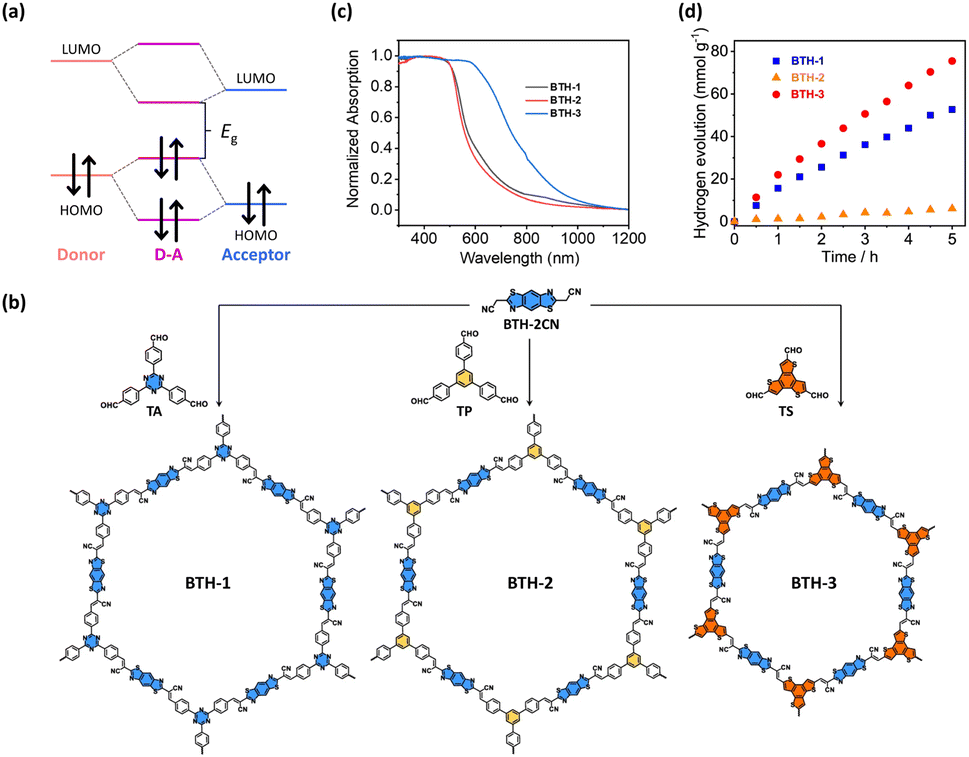 | ||
| Fig. 15 (a) Diagram of molecular orbital interaction between donor and acceptor moieties and the formation of a new bandgap in D–A components. (b) Synthetic procedures of BTH-1, BTH-2, BTH-3. (c) Corresponding absorption spectra. (d) Results of photocatalytic H2 production under visible light illumination over the three samples. Reproduced with permission from ref. 116. Copyright 2022, Springer Nature. | ||
5.3 Pros and cons
2D or 3D porous structures inherent to COFs are theoretically limitless, owing to the vast array of knot and linker units that can be synthesized through organic synthetic protocols. The versatility of these building blocks allows for the precise design and customization of COFs, leading to an expansive diversity of structures with tailor-made pore sizes, geometries, and functionalities. This adaptability makes COFs highly suitable for a range of catalytic applications. The synthesis of crystalline COFs necessitates the incorporation of specific functional groups, which often involves complex multi-step synthetic procedures.117 This can elevate the production costs due to the laborious nature of these processes. Additionally, the polycondensation reactions used to link monomer units into COFs demand extensive optimization, further contributing to the complexity and expense of COF development.118 While COFs are regarded as chemically more stable than MOFs due to the nature of their reversible covalent bonds, this reversibility can present a conundrum. There is a compromise between the crystallinity and stability of COFs. Achieving high crystallinity in COFs may lead to a reduction in their stability, and enhancing stability could result in lower crystallinity of COF.117,119Many COFs are synthesized as nanocrystalline samples, which imposes additional challenges for structural characterization.120 This complexity obscures the clear elucidation of the photocatalytic mechanisms tied to their well-ordered structures. In contrast, MOFs boast well-defined and tailorable porous structures with high crystallinity, which can be more straightforwardly assessed through crystallographic techniques. This clarity in structural definition aids in the exploration of the interplay between the microstructure of MOFs and their photocatalytic properties.121 Moreover, the metal centers within MOFs serve as catalytic sites for a multitude of complex reactions,122 underscoring the multifunctionality of MOFs in photocatalytic applications. This versatility, combined with the more accessible structural analysis, positions MOFs as more feasible candidates for photocatalyst applications compared to COFs. Despite the promising attributes of COFs, MOFs currently stand out as the more practical option for photocatalysis owing to their well-characterized structures and versatile catalytic capabilities.
6. Summary and perspectives
As summarized in Table 1, manipulating the charge transfer dynamics of MOFs through composition engineering and heterojunction incorporation can provide a concise picture and knowledge for the creation of robust photocatalytic systems for desired usage based on MOFs. As highlighted in this minireview, considerable efforts have been dedicated to modulating the interfacial charge dynamics of MOF-based photocatalysts for performance optimization. Other approaches that have been adapted in semiconductor-based photocatalytic systems can also be applied to tailor the photocatalytic properties of MOFs. For example, by maneuvering electric and magnetic fields,123–127 the behavior of charge transfer of MOFs can also be managed to enable activity maximization. Considering these advancements, certain measures must be taken to overcome challenges currently facing MOF-based photocatalysts in order to accelerate their widespread application. First, a comprehensive understanding of the charge transfer pathways involved in the whole photocatalytic process is indispensable, especially for those containing parallel and sequential reaction steps.128,129 Monitoring individual charge transfer pathways and piecing together the chain of events is important for establishing a veritable working mechanism. How to design experimental procedures to identify the spectral signatures of specific charge transfer pathways is essential for clarifying the charge transfer scenario. In this regard, adding suitable scavengers to determine the signals of associated species can provide an intelligent approach to directly probe the dynamics of the species of interest.130,131 However, the produced data can be complex and challenging to interpret. Advanced data analysis with the aid of models and algorithms may be necessary to extract meaningful information.132 Besides time-resolved PL and TA, transient surface photovoltage also offers a valuable tool for studying the charge transfer and separation efficiency of photocatalysts.133 This technique involves monitoring the change in the surface potential of a photocatalyst upon exposure to light. When charge carriers reach the surface of the photocatalyst, they induce a change in the local electric field, which in turn affects the surface potential. The separation of charges creates a spatial charge distribution that can be detected as a transient surface photovoltage. By analyzing these signals, the effectiveness of charge carrier generation, separation, and transportation can be inferred, providing crucial information for understanding interfacial charge dynamics of a photocatalyst. On the other hand, real-time observations of the charge transfer dynamics of MOF-based photocatalysts under working conditions are important for elucidating the intricate mechanistic details. Specifically, the influence of external factors, such as the presence of reactants and electrolytes and changes in pH and temperature, must be assessed. While the in situ time-resolved PL and TA studies can offer invaluable insights, the challenges associated with experimental complexity, sample preparation, and data analysis need to be addressed. Other real-time analytical techniques, such as in situ X-ray photoelectron spectroscopy134,135 and operando Raman spectroscopy,136,137 can provide complementary information to the establishment of a veritable working mechanism.| MOFs | Modification | Photocatalytic application | Charge dynamics | Reference |
|---|---|---|---|---|
| [Sr(NH2-BDC)(DMF)]n | Sr/Fe | N2 reduction | Prolonged PL lifetime for long-lived carriers | 37 |
| UiO-67(bpydc) | Co/Ru | CO2 reduction | Shortened PL lifetime for efficient electron transfer | 38 |
| PBA | FeNix | CO2 reduction | Shortened PL lifetime for efficient electron transfer | 39 |
| UiO-66 | –SCH3 & –SOCH3 | H2 production | Shortened TA lifetime for fast charge relaxation | 40 |
| MIL-125-NH2 | RV2+ | CO2 reduction | Prolonged PL lifetime for mitigated electron trapping | 41 |
| MET-Cu | Linker vacancies | H2 production | Shortened PL lifetime for efficient electron transfer | 42 |
| UiO-66 | Linker vacancies | CO2 reduction | Shortened PL lifetime for efficient electron transfer | 43 |
| UiO-66 | CdS (type-II) | H2 production | Shortened TA lifetime for efficient electron transfer | 92 |
| MOF-808 | CdS (type-II) | H2 production | Shortened TA lifetime for efficient electron transfer | 93 |
| Cu3(BTC)2 | Cu2O (type-II) | CO2 reduction | Shortened TA lifetime for efficient electron transfer | 94 |
| UiO-66 | g-C3N4 (type-II) | H2 production | Shortened PL lifetime for efficient electron transfer | 95 |
| UiO-66-(COOH)2 | ZnIn2S4 (Z-scheme) | H2 production & Cr6+ reduction | Prolonged PL lifetime for prevalence of interfacial charge recombination | 96 |
| Al-TCPP | Pt single metal | H2 production | Shortened TA lifetime for efficient electron transfer | 97 |
| UiO-68-NH2 | Pt metal | CO2 reduction | Shortened PL lifetime for efficient electron transfer | 98 |
| PCN-222-Ni | UiO-67-NH2 (Z-scheme) | CO2 reduction | Shortened PL lifetime for efficient electron transfer | 99 |
| Fe-MOF | Ni-MOF | CO2 reduction | Shortened PL lifetime for efficient electron transfer | 100 |
Furthermore, similar to the future blueprint in other photocatalyst categories,61,138,139 near-infrared responsive MOFs are urgently needed and are necessary for realizing wide-spectrum-driven photocatalysis. The answer to this problem may involve introducing organic linkers with intrinsic near-infrared absorption. Successful examples have included large π-conjugated porphyrin linkers128 and ruthenium complexes with π-conjugation ligands.140 Due to the prevalence of ligand-to-cluster or ligand-to-ligand charge transfer, photoexcited charge carriers can be secured to carry out efficient photocatalytic reactions. An additional approach to the development of near-infrared responsive MOFs can also be realized by means of upconversion nanoparticle integration.141,142 By maneuvering the untapped near-infrared energy to harness the entire solar spectrum, the photocatalytic performance of MOFs can be increased to an advanced level. When exploiting near-infrared responsive MOFs, conventional trial-and-error attempts in materials synthesis should be avoided. In this sense, a paradigm shift in the design of next-generation photocatalysts has occurred with data-driven materials and methods to search and screen through machine learning143,144 Due to the advancement in mathematical algorithms, large-scale data analysis can be managed to accelerate the identification of the target MOFs. The concurrent examination of interfacial charge dynamics for the developed near-infrared responsive MOFs is also essential for bridging the gap between fundamental knowledge and practical applications. However, accessing state-of-the-art instrumentation that enables probing charge transfer processes in near-infrared spectral regions is technically challenging, which can be a barrier for researchers from other disciplines. Addressing these challenges will be the principal for pushing forward the blossoming development of near-infrared responsive MOFs in photocatalysis. Overall, by linking interfacial charge dynamics to photocatalytic performance, this mini review establishes the design rules and principles for engineering MOFs with superior capabilities and widens the horizon of possibilities for continuously using MOFs in advanced photocatalytic reactions.
Author contributions
Chien-Yi Wang: conceptualization, investigation, writing – original draft; Huai-En Chang: conceptualization, investigation, writing-original draft; Cheng-Yu Wang: conceptualization, project administration, supervision, writing – review & editing; Tomoyuki Kurioka: conceptualization, project administration, supervision, writing – review & editing; Chun-Yi Chen: conceptualization, investigation; Tso-Fu Mark Chang: conceptualization, investigation; Masato Sone: conceptualization, investigation; Yung-Jung Hsu: conceptualization, funding acquisition, project administration, supervision, writing – review & editing.Conflicts of interest
There are no conflicts to declare.Acknowledgements
This work is financially supported by the National Science and Technology Council, Taiwan under grants NSTC 111-2113-M-A49-038, NSTC 112-2113-M-A49-024, MOST 111-2628-E-A49-001-MY3, NSTC 112-2221-E-A49-035-MY2, and NSTC 112-2218-E-008-014, and by JSPS KAKENHI with Grant Numbers JP22K20475 and JP23K13557. This work is also supported by the Center for Emergent Functional Matter Science of National Yang Ming Chiao Tung University from The Featured Areas Research Center Program within the framework of the Higher Education Sprout Project by the Ministry of Education (MOE) in Taiwan. This work is supported in part by the World Research Hub (WRH) Program of the International Research Frontiers Initiative, Tokyo Institute of Technology.Notes and references
- G. L. Yang, X. J. Che, S. L. Hou, C. S. Cao and B. Zhao, Inorg. Chem., 2021, 60, 1922–1929 CrossRef CAS PubMed.
- S. Kampouri, F. M. Ebrahim, M. Fumanal, M. Nord, P. A. Schouwink, R. Elzein, R. Addou, G. S. Herman, B. Smit, C. P. Ireland and K. C. Stylianou, ACS Appl. Mater. Interfaces, 2021, 13, 14239–14247 CrossRef CAS PubMed.
- Z. Wang, L. Zeng, C. He and C. Duan, ACS Appl. Mater. Interfaces, 2021, 13, 25898–25905 CrossRef CAS PubMed.
- S. Fu, S. Yao, S. Guo, G. C. Guo, W. Yuan, T. B. Lu and Z. M. Zhang, J. Am. Chem. Soc., 2021, 143, 20792–20801 CrossRef CAS PubMed.
- J. Tang and J. Wang, Environ. Sci. Technol., 2018, 52, 5367–5377 CrossRef CAS PubMed.
- J. Liu, L. Chen, H. Cui, J. Zhang, L. Zhang and C. Y. Su, Chem. Soc. Rev., 2014, 43, 6011–6061 RSC.
- X. Feng, J. Hajek, H. S. Jena, G. Wang, S. K. P. Veerapandian, R. Morent, N. DeGeyter, K. Leyssens, A. E. J. Hoffman, V. Meynen, C. Marquez, D. E. DeVos, V. VanSpeybroeck, K. Leus and P. V. DerVoort, J. Am. Chem. Soc., 2020, 142, 3174–3183 CrossRef CAS PubMed.
- F. G. Cirujano and F. X. Xamena, J. Phys. Chem. Lett., 2020, 11, 4879–4890 CrossRef CAS PubMed.
- L. T. Guo, Y. Y. Cai, J. M. Ge, Y. N. Zhang, L. H. Gong, X. H. Li, K. X. Wang, Q. Z. Ren, J. Su and J. S. Chen, ACS Catal., 2015, 5, 388–392 CrossRef CAS.
- H. J. Son, S. Jin, S. Patwardhan, S. J. Wezenberg, N. C. Jeong, M. So, C. E. Wilmer, A. A. Sarjeant, G. C. Schatz, R. Q. Snurr, O. K. Farha, G. P. Wiederrecht and J. T. Hupp, J. Am. Chem. Soc., 2013, 135, 862–869 CrossRef CAS PubMed.
- L. Liu, S. Du, X. Guo, Y. Xiao, Z. Yin, N. Yang, Y. Bao, X. Zhu, S. Jin, Z. Feng and F. Zhang, J. Am. Chem. Soc., 2022, 144, 2747–2754 CrossRef CAS PubMed.
- J. Long, S. Wang, Z. Ding, S. Wang, Y. Zhou, L. Huang and X. Wang, Chem. Commun., 2012, 48, 11656–11658 RSC.
- X. Zhang, J. Wang, X. X. Dong and Y. K. Lv, Chemosphere, 2020, 242, 125144 CrossRef CAS PubMed.
- S. Liu, C. Zhang, Y. Sun, Q. Chen, L. He, K. Zhang, J. Zhang, B. Liu and L. F. Chen, Coord. Chem. Rev., 2020, 413, 213266 CrossRef CAS.
- R. Li, W. Zhang and K. Zhou, Adv. Mater., 2018, 30, 1705512 CrossRef PubMed.
- L. Fan, Q. Yu, J. Chen, U. Khan, X. Wang and J. Gao, Catalysts, 2022, 12, 1005 CrossRef CAS.
- C. W. Tsao, M. J. Fang and Y. J. Hsu, Coord. Chem. Rev., 2021, 438, 213876 CrossRef CAS.
- Y. L. Liu, X. Y. Liu, L. Feng, L. X. Shao, S. J. Li, J. Tang, H. Cheng, Z. Chen, R. Huang, H. C. Xu and J. L. Zhuang, ChemSusChem, 2022, 15, e202102603 CrossRef CAS PubMed.
- S. Subudhi, S. P. Tripathy and K. Parida, Inorg. Chem. Front., 2021, 8, 1619–1636 RSC.
- J. Guo, Y. Wan, Y. Zhu, M. Zhao and Z. Tang, Nano Res., 2021, 14, 2037–2052 CrossRef CAS.
- C. W. Huang, V. H. Nguyen, S. R. Zhou, S. Y. Hsu, J. X. Tan and K. C. W. Wu, Sustainable Energy Fuels, 2020, 4, 504–521 RSC.
- C. Cai, G. Fan, B. Du, Z. Chen, J. Lin, S. Yang, X. Lin and X. Li, Catal. Sci. Technol., 2022, 12, 3767–3777 RSC.
- D. Li, M. Kassymova, X. Cai, S. Q. Zang and H. L. Jiang, Coord. Chem. Rev., 2020, 412, 213262 CrossRef CAS.
- G. Lu, F. Chu, X. Huang, Y. Li, K. Liang and G. Wang, Coord. Chem. Rev., 2022, 450, 214240 CrossRef CAS.
- É. Whelan, F. W. Steuber, T. Gunnlaugsson and W. Schmitt, Coord. Chem. Rev., 2021, 437, 213757 CrossRef.
- J. Cao, Z. Yang, W. Xiong, Y. Zhou, Y. Wu, M. Jia, C. Zhou and Z. Xu, Coord. Chem. Rev., 2021, 439, 213924 CrossRef CAS.
- C. I. Ezugwu, S. Liu, C. Li, S. Zhuiykov, S. Roy and F. Verpoort, Coord. Chem. Rev., 2022, 450, 214245 CrossRef CAS.
- N. Kolobov, M. G. Goesten and J. Gascon, Angew. Chem., Int. Ed., 2021, 60, 26038–26052 CrossRef CAS PubMed.
- R. Jaryal, R. Kumar and S. Khullar, Coord. Chem. Rev., 2022, 464, 214542 CrossRef CAS.
- H. Liu, M. Cheng, Y. Liu, J. Wang, G. Zhang, L. Li, L. Du, G. Wang, S. Yang and X. Wang, Energy Environ. Sci., 2022, 15, 3722–3749 RSC.
- H. Lin, Y. Xu, B. Wang, D. S. Li, T. Zhou and J. Zhang, Small Struct., 2022, 3, 2100176 CrossRef CAS.
- X. Li, S. Surendran Rajasree, J. Yu and P. Deria, Dalton Trans., 2020, 49, 12892–12917 RSC.
- M. R. diNunzio, E. C. Mancebo, B. Cohen and A. Douhal, J. Photochem. Photobiol., C, 2020, 44, 100355 CrossRef CAS.
- T. H. Lai, K. I. Katsumata and Y. J. Hsu, Nanophotonics, 2020, 10, 777–795 CrossRef.
- J. Hu, C. Chen, H. Yang, F. Yang, J. Qu, X. Yang, W. Sun, L. Dai and C. M. Li, Appl. Catal., B, 2022, 317, 121723 CrossRef CAS.
- X. Li, J. Hu, T. Yang, X. Yang, J. Qu and C. M. Li, Nano Energy, 2022, 92, 106714 CrossRef CAS.
- Z. Zhao, H. Ren, D. Yang, Y. Han, J. Shi, K. An, Y. Chen, Y. Shi, W. Wang, J. Tan, X. Xin, Y. Zhang and Z. Jiang, ACS Catal., 2021, 11, 9986–9995 CrossRef CAS.
- M. Liu, Y. F. Mu, S. Yao, S. Guo, X. W. Guo, Z. M. Zhang and T. B. Lu, Appl. Catal., B, 2019, 245, 496–501 CrossRef CAS.
- M. Lin, Y. Luo, T. Zhang, X. Shen, Z. Zhuang and Y. Yu, ACS Appl. Mater. Interfaces, 2022, 14, 52868–52876 CrossRef CAS PubMed.
- T. F. Chen, L. Y. Wang, Y. F. Wang, H. Gao, J. He, G. Wang, X. F. Meng, Y. S. Wu, Y. H. Deng and C. Q. Wan, ACS Appl. Mater. Interfaces, 2021, 13, 20897–20905 CrossRef CAS PubMed.
- T. Wang, L. Zhang, J. Liu, X. X. Li, L. Yuan, S. L. Li and Y. Q. Lan, Chem. Commun., 2022, 58, 7507–7510 RSC.
- Z. D. Wang, Y. Zang, Z. J. Liu, P. Peng, R. Wang and S. Q. Zang, Appl. Catal., B, 2021, 288, 119941 CrossRef CAS.
- Y. He, C. Li, X. B. Chen, Z. Shi and S. Feng, ACS Appl. Mater. Interfaces, 2022, 14, 28977–28984 CrossRef CAS PubMed.
- X. You, H. Wu, R. Zhang, Y. Su, L. Cao, Q. Yu, J. Yuan, K. Xiao, M. He and Z. Jiang, Nat. Commun., 2019, 10, 4160 CrossRef CAS PubMed.
- R. G. Pearson, J. Am. Chem. Soc., 1963, 85, 3533–3539 CrossRef CAS.
- C. H. Hendon, D. Tiana, M. Fontecave, C. Sanchez, L. D'Arras, C. Sassoye, L. Rozes, C. M. Draznieks and A. Walsh, J. Am. Chem. Soc., 2013, 135, 10942–10945 CrossRef CAS PubMed.
- T. F. Chen, S. Y. Han, Z. P. Wang, H. Gao, L. Y. Wang, Y. H. Deng, C. Q. Wan, Y. Tian, Q. Wang, G. Wang and G. S. Li, Appl. Catal., B, 2019, 259, 118047 CrossRef CAS.
- S. Y. Han, D. L. Pan, H. Chen, X. B. Bu, Y. X. Gao, H. Gao, Y. Tian, G. S. Li, G. Wang, S. L. Cao, C. Q. Wan and G. C. Guo, Angew. Chem., 2018, 130, 10012–10017 CrossRef.
- K. Hendrickx, D. E. P. Vanpoucke, K. Leus, K. Lejaeghere, A. V. D. Deyne, V. VanSpeybroeck, P. Van DerVoort and K. Hemelsoet, Inorg. Chem., 2015, 54, 10701–10710 CrossRef CAS PubMed.
- W. Xiang, Y. Zhang, Y. Chen, C. J. Liu and X. Tu, J. Mater. Chem. A, 2020, 8, 21526–21546 RSC.
- Z. Fang, B. Bueken, D. E. DeVos and R. A. Fischer, Angew. Chem., Int. Ed., 2015, 54, 7234–7254 CrossRef CAS PubMed.
- W. Xu, Y. Zhang, J. Wang, Y. Xu, L. Bian, Q. Ju, Y. Wang and Z. Fang, Nat. Commun., 2022, 13, 2068 CrossRef CAS PubMed.
- W. Wang, T. Sheng, S. Chen, Z. Xiang, F. Zhou, W. Zhu and H. Wang, Chem. Eng. J., 2023, 453, 139711 CrossRef CAS.
- C. A. Suárez, S. P. Beltran, G. E. R. Caballero and P. B. Balbuena, Catal. Sci. Technol., 2018, 8, 847–857 RSC.
- C. Montoro, P. Ocón, F. Zamora and J. A. R. Navarro, Chem. – Eur. J., 2016, 22, 1646–1651 CrossRef CAS PubMed.
- M. Taddei, G. M. Schukraft, M. E. A. Warwick, D. Tiana, M. J. McPherson, D. R. Jones and C. Petit, J. Mater. Chem. A, 2019, 7, 23781–23786 RSC.
- I. A. Lázaro, H. Szalad, P. Valiente, J. Albero, H. García and C. M. Gastaldo, ACS Appl. Mater. Interfaces, 2022, 14, 21007–21017 CrossRef PubMed.
- I. Abánades Lázaro, C. J. R. Wells and R. S. Forgan, Angew. Chem., Int. Ed., 2020, 59, 5211–5217 CrossRef PubMed.
- G. Cai and H. L. Jiang, Angew. Chem., Int. Ed., 2017, 56, 563–567 CrossRef CAS PubMed.
- Y. A. Chen, Y. T. Wang, H. S. Moon, K. Yong and Y. J. Hsu, RSC Adv., 2021, 11, 12288–12305 RSC.
- M. J. Fang, C. W. Tsao and Y. J. Hsu, J. Phys. D Appl. Phys., 2020, 53, 143001 CrossRef CAS.
- F. Yang, J. Qu, Y. Zheng, Y. Cai, X. Yang, C. M. Li and J. Hu, Nanoscale, 2022, 14, 15217–15241 RSC.
- M. Y. Kuo, C. F. Hsiao, Y. H. Chiu, T. H. Lai, M. J. Fang, J. Y. Wu, J. W. Chen, C. L. Wu, K. H. Wei, H. C. Lin and Y. J. Hsu, Appl. Catal., B, 2019, 242, 499–506 CrossRef CAS.
- Y. C. Pu, W. T. Chen, M. J. Fang, Y. L. Chen, K. A. Tsai, W. H. Lin and Y. J. Hsu, J. Mater. Chem. A, 2018, 6, 17503–17513 RSC.
- W. H. Lin, Y. H. Chiu, P. W. Shao and Y. J. Hsu, ACS Appl. Mater. Interfaces, 2016, 8, 32754–32763 CrossRef CAS PubMed.
- Y. H. Hsu, A. T. Nguyen, Y. H. Chiu, J. M. Li and Y. J. Hsu, Appl. Catal., B, 2016, 185, 133–140 CrossRef CAS.
- W. T. Chen, Y. K. Lin, T. T. Yang, Y. C. Pu and Y. J. Hsu, Chem. Commun., 2013, 49, 8486–8488 RSC.
- T. H. Lai, C. W. Tsao, M. J. Fang, J. Y. Wu, Y. P. Chang, Y. H. Chiu, P. Y. Hsieh, M. Y. Kuo, K. D. Chang and Y. J. Hsu, ACS Appl. Mater. Interfaces, 2022, 14, 40771–40783 CrossRef CAS PubMed.
- Y. H. Chiu, S. B. Naghadeh, S. A. Lindley, T. H. Lai, M. Y. Kuo, K. D. Chang, J. Z. Zhang and Y. J. Hsu, Nano Energy, 2019, 62, 289–298 CrossRef CAS.
- Y. H. Chiu, K. D. Chang and Y. J. Hsu, J. Mater. Chem. A, 2018, 6, 4286–4296 RSC.
- Y. C. Pu, G. Wang, K. D. Chang, Y. Ling, Y. K. Lin, B. C. Fitzmorris, C. M. Liu, X. Lu, Y. Tong, J. Z. Zhang, Y. J. Hsu and Y. Li, Nano Lett., 2013, 13, 3817–3823 CrossRef CAS PubMed.
- T. Yang, Y. Shao, J. Hu, J. Qu, X. Yang, F. Yang and C. Ming Li, Chem. Eng. J., 2022, 448, 137613 CrossRef CAS.
- M. Wang, Y. S. Chang, C. W. Tsao, M. J. Fang, Y. J. Hsu and K. L. Choy, Chem. Commun., 2019, 55, 2465–2468 RSC.
- P. Y. Hsieh, Y. H. Chiu, T. H. Lai, M. J. Fang, Y. T. Wang and Y. J. Hsu, ACS Appl. Mater. Interfaces, 2019, 11, 3006–3015 CrossRef CAS PubMed.
- Y. S. Chang, M. Choi, M. Baek, P. Y. Hsieh, K. Yong and Y. J. Hsu, Appl. Catal., B, 2018, 225, 379–385 CrossRef CAS.
- M. Y. Chen and Y. J. Hsu, Nanoscale, 2013, 5, 363–368 RSC.
- Y. F. Lin and Y. J. Hsu, Appl. Catal., B, 2013, 130–131, 93–98 CrossRef CAS.
- Y. C. Chen, Y. C. Pu and Y. J. Hsu, J. Phys. Chem. C, 2012, 116, 2967–2975 CrossRef CAS.
- Y. H. Chiu and Y. J. Hsu, Nano Energy, 2017, 31, 286–295 CrossRef CAS.
- W. C. Hu, Y. A. Chen, P. Y. Hsieh, C. W. Tsao, Y. H. Chiu, T. F. M. Chang, C. Y. Chen, M. Sone and Y. J. Hsu, J. Taiwan Inst. Chem. Eng., 2020, 112, 337–344 CrossRef CAS.
- Y. C. Pu, H. Y. Chou, W. S. Kuo, K. H. Wei and Y. J. Hsu, Appl. Catal., B, 2017, 204, 21–32 CrossRef CAS.
- K. A. Tsai and Y. J. Hsu, Appl. Catal., B, 2015, 164, 271–278 CrossRef CAS.
- Y. C. Chen, K. Katsumata, Y. H. Chiu, K. Okada, N. Matsushita and Y. J. Hsu, Appl. Catal., A, 2015, 490, 1–9 CrossRef CAS.
- J. M. Li, C. W. Tsao, M. J. Fang, C. C. Chen, C. W. Liu and Y. J. Hsu, ACS Appl. Nano Mater., 2018, 1, 6843–6853 CrossRef CAS.
- J. Hu, C. Chen, Y. Zheng, G. Zhang, C. Guo and C. M. Li, Small, 2020, 16, 2002988 CrossRef CAS PubMed.
- I. Hong, Y. A. Chen, Y. J. Hsu and K. Yong, ACS Appl. Mater. Interfaces, 2021, 13, 52670–52680 CrossRef CAS PubMed.
- J. M. Li, H. Y. Cheng, Y. H. Chiu and Y. J. Hsu, Nanoscale, 2016, 8, 15720–15729 RSC.
- Y. C. Pu, W. H. Lin and Y. J. Hsu, Appl. Catal., B, 2015, 163, 343–351 CrossRef CAS.
- A. Iwase, Y. H. Ng, Y. Ishiguro, A. Kudo and R. Amal, J. Am. Chem. Soc., 2011, 133, 11054–11057 CrossRef CAS PubMed.
- G. E. M. Schukraft, B. Moss, A. G. Kafizas and C. Petit, ACS Appl. Mater. Interfaces, 2022, 14, 19342–19352 CrossRef CAS PubMed.
- M. Liu, Z. Xing, Z. Li and W. Zhou, Coord. Chem. Rev., 2021, 446, 214123 CrossRef CAS.
- H. Q. Xu, S. Yang, X. Ma, J. Huang and H. L. Jiang, ACS Catal., 2018, 8, 11615–11621 CrossRef CAS.
- A. Ghosh, S. Karmakar, F. A. Rahimi, R. S. Roy, S. Nath, U. K. Gautam and T. K. Maji, ACS Appl. Mater. Interfaces, 2022, 14, 25220–25231 CrossRef CAS PubMed.
- X. Deng, R. Li, S. Wu, L. Wang, J. Hu, J. Ma, W. Jiang, N. Zhang, X. Zheng, C. Gao, L. Wang, Q. Zhang, J. Zhu and Y. Xiong, J. Am. Chem. Soc., 2019, 141, 10924–10929 CrossRef CAS PubMed.
- R. Wang, L. Gu, J. Zhou, X. Liu, F. Teng, C. Li, Y. Shen and Y. Yuan, Adv. Mater. Interfaces, 2015, 2, 1500037 CrossRef.
- F. Mu, Q. Cai, H. Hu, J. Wang, Y. Wang, S. Zhou and Y. Kong, Chem. Eng. J., 2020, 384, 123352 CrossRef CAS.
- X. Fang, Q. Shang, Y. Wang, L. Jiao, T. Yao, Y. Li, Q. Zhang, Y. Luo and H. L. Jiang, Adv. Mater., 2018, 30, 1705112 CrossRef PubMed.
- F. Guo, Y. P. Wei, S. Q. Wang, X. Y. Zhang, F. M. Wang and W. Y. Sun, J. Mater. Chem. A, 2019, 7, 26490–26495 RSC.
- H. B. Huang, Z. B. Fang, R. Wang, L. Li, M. Khanpour, T. F. Liu and R. Cao, Small, 2022, 18, 2200407 CrossRef CAS PubMed.
- L. Gu, G. Deng, R. Huang and X. Shi, Nanoscale, 2022, 14, 15821–15831 RSC.
- Y. Wang, Y. Yu, R. Li, H. Liu, W. Zhang, L. Ling, W. Duan and B. Liu, J. Mater. Chem. A, 2017, 5, 20136–20140 RSC.
- K. Wu, H. Zhu, Z. Liu, W. R. Córdoba and T. Lian, J. Am. Chem. Soc., 2012, 134, 10337–10340 CrossRef CAS PubMed.
- H. Zhu, N. Song and T. Lian, J. Am. Chem. Soc., 2010, 132, 15038–15045 CrossRef CAS PubMed.
- A. Dhakshinamoorthy, A. M. Asiri and H. García, Angew. Chem., Int. Ed., 2016, 55, 5414–5445 CrossRef CAS PubMed.
- D. Jiang, P. Xu, H. Wang, G. Zeng, D. Huang, M. Chen, C. Lai, C. Zhang, J. Wan and W. Xue, Coord. Chem. Rev., 2018, 376, 449–466 CrossRef CAS.
- K. Sun, Y. Qian and H. L. Jiang, Angew. Chem., Int. Ed., 2023, 62, e202217565 CrossRef CAS PubMed.
- Y. Zhang, H. Liu, F. Gao, X. Tan, Y. Cai, B. Hu, Q. Huang, M. Fang and X. Wang, EnergyChem, 2022, 4, 100078 CrossRef CAS.
- K. Geng, T. He, R. Liu, S. Dalapati, K. T. Tan, Z. Li, S. Tao, Y. Gong, Q. Jiang and D. Jiang, Chem. Rev., 2020, 120, 8814–8933 CrossRef CAS PubMed.
- J. Wang and S. Zhuang, Coord. Chem. Rev., 2019, 400, 213046 CrossRef CAS.
- X. Liu, H. Pang, X. Liu, Q. Li, N. Zhang, L. Mao, M. Qiu, B. Hu, H. Yang and X. Wang, Innovation, 2021, 2, 100076 CAS.
- A. P. Côté, A. I. Benin, N. W. Ockwig, M. O'Keeffe, A. J. Matzger and O. M. Yaghi, Science, 2005, 310, 1166–1170 CrossRef PubMed.
- O. M. Yaghi, G. Li and H. Li, Nature, 1995, 378, 703–706 CrossRef CAS.
- S. Bi, Z. A. Lan, S. Paasch, W. Zhang, Y. He, C. Zhang, F. Liu, D. Wu, X. Zhuang, E. Brunner, X. Wang and F. Zhang, Adv. Funct. Mater., 2017, 27, 1703146 CrossRef.
- S. Bi, C. Yang, W. Zhang, J. Xu, L. Liu, D. Wu, X. Wang, Y. Han, Q. Liang and F. Zhang, Nat. Commun., 2019, 10, 2467 CrossRef PubMed.
- C. B. Meier, R. S. Sprick, A. Monti, P. Guiglion, J. S. M. Lee, M. A. Zwijnenburg and A. I. Cooper, Polymer, 2017, 126, 283–290 CrossRef CAS.
- Y. Wang, W. Hao, H. Liu, R. Chen, Q. Pan, Z. Li and Y. Zhao, Nat. Commun., 2022, 13, 100 CrossRef CAS PubMed.
- F. Haase and B. VLotsch, Chem. Soc. Rev., 2020, 49, 8469–8500 RSC.
- R. Freund, O. Zaremba, G. Arnauts, R. Ameloot, G. Skorupskii, M. Dincă, A. Bavykina, J. Gascon, A. Ejsmont, J. Goscianska, M. Kalmutzki, U. Lächelt, E. Ploetz, C. S. Diercks and S. Wuttke, Angew. Chem., Int. Ed., 2021, 60, 23975–24001 CrossRef CAS PubMed.
- F. Haase, E. Troschke, G. Savasci, T. Banerjee, V. Duppel, S. Dörfler, M. M. J. Grundei, A. M. Burow, C. Ochsenfeld, S. Kaskel and B. V. Lotsch, Nat. Commun., 2018, 9, 2600 CrossRef PubMed.
- A. L. Magano, A. J. Almarza, J. Alemán and R. M. Ballesté, Catalysts, 2020, 10, 120 CrossRef.
- J. D. Xiao and H. L. Jiang, Acc. Chem. Res., 2019, 52, 356–366 CrossRef CAS PubMed.
- A. Dhakshinamoorthy, Z. Li and H. Garcia, Chem. Soc. Rev., 2018, 47, 8134–8172 RSC.
- B. Dai, G. M. Biesold, M. Zhang, H. Zou, Y. Ding, Z. L. Wang and Z. Lin, Chem. Soc. Rev., 2021, 50, 13646–13691 RSC.
- B. Dai, J. Guo, C. Gao, H. Yin, Y. Xie and Z. Lin, Adv. Mater., 2023, 35, 2210914 CrossRef CAS PubMed.
- B. Dai, J. Fang, Y. Yu, M. Sun, H. Huang, C. Lu, J. Kou, Y. Zhao and Z. Xu, Adv. Mater., 2020, 32, 1906361 CrossRef CAS PubMed.
- B. Dai, Y. Zhou, X. Xiao, Y. Chen, J. Guo, C. Gao, Y. Xie and J. Chen, Adv. Sci., 2022, 9, 2203057 CrossRef CAS PubMed.
- B. Dai, H. Feng, Z. Li and Y. Xie, Sci. Bull., 2022, 67, 779–783 CrossRef CAS PubMed.
- J. Y. Zeng, X. S. Wang, B. R. Xie, Q. R. Li and X. Z. Zhang, J. Am. Chem. Soc., 2022, 144, 1218–1231 CrossRef CAS PubMed.
- A. G. Sánchez, M. G. Mendoza, M. Barawi, I. J. V. Garcia, M. Liras, F. Gándara and V. A. dela Peña O'Shea, J. Am. Chem. Soc., 2020, 142, 318–326 CrossRef PubMed.
- J. G. Santaclara, A. I. O. Suarez, I. duFossé, A. Houtepen, J. Hunger, F. Kapteijn, J. Gascon and M. A. van derVeen, Faraday Discuss., 2017, 201, 71–86 RSC.
- Z. Lian, Z. Li, F. Wu, Y. Zhong, Y. Liu, W. Wang, J. Zi and W. Yang, Commun. Chem., 2022, 5, 93 CrossRef CAS PubMed.
- M. Y. Kuo, N. Spitha, M. P. Hautzinger, P. L. Hsieh, J. Li, D. Pan, Y. Zhao, L. J. Chen, M. H. Huang, S. Jin, Y. J. Hsu and J. C. Wright, J. Am. Chem. Soc., 2021, 143, 4969–4978 CrossRef CAS PubMed.
- J. Hu, X. Li, J. Qu, X. Yang, Y. Cai, T. Yang, F. Yang and C. M. Li, Chem. Eng. J., 2023, 453, 139957 CrossRef CAS.
- Z. Jin and X. Wang, Mater. Today Energy, 2022, 30, 101164 CrossRef CAS.
- Y. Zhang, J. Zhao, H. Wang, B. Xiao, W. Zhang, X. Zhao, T. Lv, M. Thangamuthu, J. Zhang, Y. Guo, J. Ma, L. Lin, J. Tang, R. Huang and Q. Liu, Nat. Commun., 2022, 13, 58 CrossRef CAS PubMed.
- J. J. Liu, Z. W. Jiang and S. W. Hsu, ACS Appl. Mater. Interfaces, 2023, 15, 6716–6725 CrossRef CAS PubMed.
- T. G. Vo, G. S. Tran, C. L. Chiang, Y. G. Lin, H. E. Chang, H. H. Kuo, C. Y. Chiang and Y. J. Hsu, Adv. Funct. Mater., 2023, 33, 2209386 CrossRef CAS.
- P. Y. Hsieh, J. Y. Wu, T. F. M. Chang, C. Y. Chen, M. Sone and Y. J. Hsu, Arabian J. Chem., 2020, 13, 8372–8387 CrossRef CAS.
- Y. H. Chiu, T. H. Lai, M. Y. Kuo, P. Y. Hsieh and Y. J. Hsu, APL Mater., 2019, 7, 080901 CrossRef.
- J. H. Tang, G. Han, G. Li, K. Yan and Y. Sun, iScience, 2022, 25, 104064 CrossRef CAS PubMed.
- D. Li, S. H. Yu and H. L. Jiang, Adv. Mater., 2018, 30, 1707377 CrossRef PubMed.
- M. Li, Z. Zheng, Y. Zheng, C. Cui, C. Li and Z. Li, ACS Appl. Mater. Interfaces, 2017, 9, 2899–2905 CrossRef CAS PubMed.
- H. Mai, T. C. Le, D. Chen, D. A. Winkler and R. A. Caruso, Chem. Rev., 2022, 122, 13478–13515 CrossRef CAS PubMed.
- J. Xie, Y. Su, D. Xue, X. Jiang, H. Fu and H. Huang, Acta Metall. Sin., 2021, 57, 1343–1361 CAS.
Footnote |
| † These authors contributed equally. |
| This journal is © The Royal Society of Chemistry 2024 |