Steric effects stabilize reverse micelle domains in supercritical CO2 by determined conformation: restrictions of water and cations†
Huiwen
Sun
a,
Meng
Wang
a,
Pan
Wang
a and
Muhan
Wang
 *abc
*abc
aDepartment of Civil Engineering, Qingdao University of Technology, Qingdao 266033, China. E-mail: wangmuhan@qut.edu.cn
bState Key Laboratory of Hydraulic Engineering Simulation and Safety, Tianjin University, Tianjin 300072, China
cSchool of Materials Science and Engineering, China University of Petroleum, Qingdao 266580, China
First published on 12th September 2023
Abstract
Previous research into designing CO2-philic surfactants has certain limitations, necessitating the exploration of effective design concepts for hydrocarbon surfactants, which are far less expensive and less toxic than fluorocarbon surfactants. In this study, molecular simulations were employed to extensively investigate preassembled models of four representative surfactants and elucidate the structure of water-in-carbon dioxide (W/C) microemulsions. Innovative strategies for evaluating the stability of surfactant microemulsions and designing CO2-philic surfactants were developed. Thorough investigations into the microemulsion structure revealed that fluorocarbon surfactants formed stable micelles due to the steric effect arising from the determined conformation, which is restricted by hydrogen bonds. Fluorination at the terminal end of the surfactant tail will lead to a more restrictive structure, acting as a steric hindrance. Investigation into a hydrocarbon surfactant also determined that the group at the surfactant tail terminal formed hydrogen bonds with water molecules, restricting the conformation of the surfactant. This is a feasible method via fluorine substitution. This work reveals that steric effects arising from water molecules and cation restrictions can guide surfactant synthesis strategies or stabilize reverse micelles in scCO2 systems. With the development of these basic design principles, the synthesis of efficient hydrocarbon surfactants will be achieved in the foreseeable future.
Design, System, ApplicationThis study is about the design and optimization of CO2-philic surfactants, intending to discover new strategies for evaluating the stability of surfactants in microemulsions and designing CO2-philic surfactants, as well as developing efficient design concepts for hydrocarbon surfactants. These surfactants can form stable micelles in supercritical carbon dioxide solvents and are cheaper and less toxic than fluorocarbon surfactants. In this study, molecular dynamics simulations were used to investigate the stability of surfactant microemulsions and to elucidate the structure of carbon dioxide-in-water microemulsions. It was found that fluorocarbon surfactants form stable micelles due to steric effects that limit their conformation, which is achieved through hydrogen bonding and fluorine substitution at the surfactant tail. Similarly, hydrogen bonding between water molecules and the tails of hydrocarbon surfactants can constrain the conformation of the surfactant and lead to a viable approach for fluorine substitution. This study aims to guide the synthetic strategy of surfactants or stabilize reverse micelles in the scCO2 system, making the production of CO2-friendly surfactants more efficient and cost-effective. |
1 Introduction
Supercritical carbon dioxide (scCO2) is considered to have huge potential as a green solvent.1 CO2 is abundant in the atmosphere and can easily attain supercritical conditions (Pc = 7.38 MPa, Tc = 31.1 °C). What is more, this solvent is non-flammable, inexpensive, selective, environmentally friendly, and generally considered to be safe.2 These advantages make scCO2 an ideal alternative solvent for the separation of petrochemical products and green oil production.3–6 Although significant progress has been achieved in using carbon dioxide for oil and gas production,7–9 challenges such as oil displacement10 or fracturing,11 as well as the low viscosity of carbon dioxide under formation conditions continue to impede the development of related technologies. These limitations need to be addressed urgently.12,13 In recent decades, research has focused on designing effective surfactant additives to improve the physical and chemical properties of scCO2 and increase its viscosity.14 The solubility characteristics of carbon dioxide (CO2) are primarily determined by its linear molecular structure, leading to a notable affinity for non-polar substances. However, the solubility of CO2 in polar substances, such as biomolecules, polymers, ions, and water, remains remarkably limited. This inherent limitation poses substantial constraints on the advancement and utilization of supercritical carbon dioxide (scCO2).15An effective approach to improve the physicochemical properties of CO2 is the addition of surfactants, which can produce stable dispersions and form water/CO2 microemulsions.16 However, most of the existing surfactants capable of forming reverse micelles in scCO2 are mainly fluorocarbon surfactants, which form reverse micelles at reasonable pressures but are expensive and environmentally unfriendly.17–25 To address these limitations, hydrocarbon surfactants have been developed as an alternative.26–28 In comparison to fluorocarbon surfactants, hydrocarbon surfactants are less expensive and less toxic, making them an attractive alternative for various applications. Despite some promising results, the majority of hydrocarbon surfactants struggle to form stable reverse micelles or only do so at high pressures.26,29–31 Therefore, novel design strategies for hydrocarbon surfactants need to be investigated.32–34
Various methods have been explored for designing surfactants suitable for use in CO2, commonly referred to as “CO2-philic” tail surfactants.35–37 Although CO2 is a non-polar molecule, as a quadrupole moment molecule, CO2 has a strong electric quadrupole moment and easily interacts with highly electronegative atoms (such as fluorine, chlorine, etc.).38–40 Thus it exhibits distinctive electrostatic properties, which enable it to form specific interactions with highly compatible polar substances.41,42 This property has garnered significant interest from researchers, particularly regarding the potential interactions between CO2 and the fluorine component in fluorocarbon surfactants. O'Neill et al. found experimentally that as the cohesive energy density decreases, the solubility of polymers in CO2 increases, which is consistent with polarization interactions and van der Waals (vdW) interactions.43 Sarbu et al. increased the solubilities of copolymers in CO2 by designing one monomer with low cohesive energy density and a large free volume and a second that provided specific acid–base interactions.44 Such strategies based on the specific interaction between fluoride and CO2 are important for the design of CO2-philic surfactants. Raveendran et al. found that acetylation of carbohydrates yielded CO2-philes with similar properties to the tails of fluorocarbon surfactants. However, the oxygenated hydrocarbon surfactant was unable to form reverse micelles with a larger volume and higher water content.45 This strong interaction between the fluorocarbon groups of the surfactants and CO2 was found to be much more pronounced in one of his ab initio studies,46 but much smaller in other studies.41 Another molecular dynamic simulation study by Stone et al. calculated the interaction between CO2 and fluorocarbon chains and found a specific interaction that showed almost no distinction from the interaction observed between CO2 and hydrocarbon chains.47 These findings suggest that the aforementioned strategies alone are insufficient for designing highly interfacially active hydrocarbon surfactants capable of forming W/C microemulsions with larger sizes or higher water content, indicating the presence of other factors influencing CO2-philic surfactants.
The formation of a microemulsion in scCO2 necessitates specific properties in the surfactants employed. Interfacial activity is the first requirement, followed by the ability to significantly reduce interfacial tension.48–50 Stone et al. calculated a simple molecular model and found that fluorocarbon surfactants have a lower fraction of free volume (FFV) in the tail region compared to their hydrogenated counterparts. This observation suggests that the separation of CO2 and water is achieved through steric hindrance.33 Following these strategies there have been many further studies, such as the investigation by Sagisaka et al.,51 who examined a series of hyperbranched hydrocarbon surfactants with decreasing free volume in the tail region and demonstrated their potential to exhibit low surface energies comparable to fluorocarbon surfactants. This new class of low-surface-energy surfactants called “hedgehog” surfactants, was then characterized using surface tension measurements and small-angle neutron scattering methods. Such strategies of reducing free volume were tested with a wide range of surfactants, and the consistent correlation between reduced FFV and enhanced stability of water-in-carbon dioxide (W/C) microemulsions aligns with numerous experimental observations across a wide range of surfactants.51–53 However, certain hydrocarbon surfactants deviate from this theory. For instance, one example exhibits a lower FFV (0.42) than the highly efficient fluorocarbon surfactant di-CF4, yet it does not perform as well in practical applications.54 This discrepancy suggests a limitation of the applicability of FFV theory in guiding the design of CO2-philic surfactants. In this paper, the molecular model structures of W/C microemulsions of four typical surfactants were investigated by molecular simulation. The unique perspective provided by atomic-level information, which is challenging to obtain experimentally, enables analysis of the interactions between water molecules or cations and surfactant tails, thereby influencing the CO2-philic nature of surfactants. A novel concept for designing hydrocarbon surfactants based on the restriction of surfactant conformations is proposed. This approach addresses the need for alternative strategies in the design of CO2-philic surfactants and offers valuable insights into the rational design of surfactants with an enhanced CO2-philic nature.
2 Models and simulation details
2.1 Modelling details
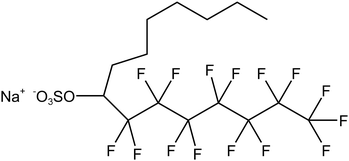
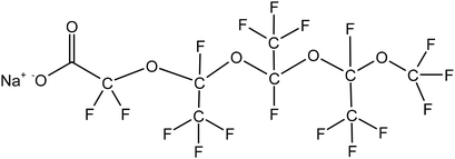
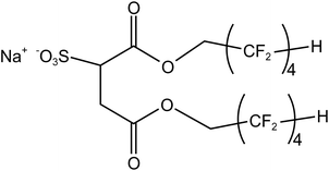
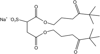
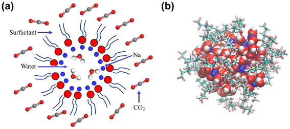
Four typical surfactants were carefully selected for molecular dynamics (MD) studies considering their representative nature, extensive prior research, practical relevance, and potential for comparative analysis.55 Namely, F7H7, PFPE, di-HCF4, and AOK, were selected for the study (see Table 1 for details). F7H7 is a hybrid surfactant consisting of one hydrocarbon and one fluorocarbon chain per molecule, while PFPE has only one perfluorinated chain. Di-HCF4 is a double-chain surfactant with fluorination at the terminal carbon atom and AOK is a ketone analog of the AOT surfactant with one carbonyl group on each tail and t-butyl at the chain tips.This study employed all-atom molecular dynamics (MD) simulations to investigate a preassembled system comprising four surfactants, water, and CO2 molecules. It has been previously observed experimentally that selected surfactants can all form microemulsion reverse micelles in scCO2,18,27,56 and the use of preassembled morphologies in simulations can increase computational efficiency.57 Therefore, the pre-assembled reverse micelles model was used in this study. Fig. 1(a) displays the structural properties of the preassembled models of surfactants. The preassembled reverse micellar spheres with an initial radius of 25 Å were composed of a water core surrounded by a spherical arrangement of surfactants in bulk CO2. Each simulation system comprised 125 water molecules, 18 sodium atoms (randomly placed in the aqueous solution), 18 surfactants, and 2467 CO2 molecules, with the number of CO2 molecules chosen based on a pressure of 20 MPa, which is sufficient for the formation of micelles by all the selected surfactants. The initial dimensions of the box are 65 Å × 65 Å × 65 Å, with periodic boundary conditions in all three directions.
2.2 Equilibrium molecular dynamics simulation
In this study, all-atom molecular dynamics (MD) were performed using LAMMPS software. The interatomic interactions were described using the COMPASS force field58 which is an ab initio-based forcefield that has been parameterized using extensive data for molecules in the condensed phase. COMPASS is capable of accurately predicting structural, conformational, vibrational, cohesive, and thermophysical properties for a wide range of compounds, both in isolation and in condensed phases.59–66 The water model of SPC/E67,68 and the rigid CO2 model of EPM2 (ref. 69) were utilized (specific parameters are provided in Table S1†). The intermolecular interaction parameters were automatically generated and derived using Materials Studio7.0 software. The initial model underwent relaxation through a series of geometry optimization runs to optimize its configuration and ensure the lowest potential energy of the starting structure. Based on this, we performed a 2 ns simulation under the NPT ensemble of 318 K and 20 MPa to obtain a reasonable system density, which prevents box fluctuations from affecting the system density. This value is close to the system density of the experimental density of scCO2 at 318 K and 20 MPa pressure ( ).70 Then the system remained at 318 K under the NVT ensemble for 6 ns MD simulation, and the data of the last 1 ns of the equilibrium system were used for the analysis. Based on previous studies by Sanjib Senapati et al.,57,71 preassembled surfactant systems can reach equilibrium within 4–5 ns. To demonstrate that the systems reached equilibrium after 6 ns, we calculated the root mean square deviation (RMSD) for each of the four systems (Fig. S1†). The reverse micelles formed after the final equilibrium are shown in Fig. 1(b). The Berendsen method was applied to the thermostat to keep the temperature of the simulation system constant.72–77 The van der Waals (vdW) interactions were calculated within a cutoff distance of 10 Å, while the long-range electrostatic interactions were treated using the Ewald summation method with a precision of 10−4 in combination with the direct pairwise interactions calculation within a real space cutoff of 10 Å.78 During the whole process, a fixed time step of 1 fs was used and data was collected every 1 ps. All the simulations were long enough for thermodynamic equilibrium and the full-precision trajectory was recorded for at least 6000 ps. We computed the average properties using the last 1000 frames of data obtained from the NVT ensemble and snapshots are output from VMD software.79
3 Results and discussion
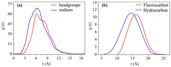
To study the coverage of surfactants on the surface of reverse micelles, Fig. 2 calculates the radial density distribution of surfactants along the centroid of the reverse micelles in the F7H7 surfactant W/C microemulsion system. In Fig. 2(a), the radial density distributions of headgroups and sodium display peaks at 6.02 Å and 6.11 Å, respectively. The headgroup distribution exhibits a single strong peak, albeit imperfect. The overlap of the peaks indicates that the movement trajectories of the headgroup and sodium atom are similar. A very broad peak means that the distance from the head group to the centroid is not the same, which means that the water core is not a regular circle, but more like an ellipse. Secondly, when calculating the density distribution from the tail to the centroid of the reverse micelles, we selected the most terminal atom of the tail for the calculation. The distance from the tail to the centroid can reflect the radius of the reverse micellar sphere. In Fig. 2(b), the radial density distribution of the hydrocarbon chain and fluorocarbon chain tail of F7H7 is shown. The hydrocarbon chain tip has a wider distribution range compared to the fluorocarbon chain tip, indicating greater flexibility of the hydrocarbon chain. Clear peaks at 14.5 Å and 15.9 Å are observed for the hydrocarbon and fluorocarbon chains, respectively. Similarly, if there are sharp and narrow peaks in the density distribution of the tails, it means that most of the tails around the micelle centroid are of the same length, and the formation of surfactants around the centroid of reverse micelles is a relatively standard round ball. However, if the peak of the curve is relatively wide, it means that the length distribution of the tail chain is very large which means there are tail chains of various lengths. The formation around the centroid is not a standard sphere, but more similar to an ellipsoid. In addition, the peak distance between the head group and the micelle centroid is about 6 Å, and the peak distance between the tail group and the micelle centroid is about 15 Å. The distribution area of the tail group is farther away from the micelle centroid than the head group. Considering the radial density distribution of the headgroups, it can be inferred that the surfactant forms a spherical structure outside the reverse micelles. The headgroup of the surfactant is towards the micelle centroid, and the tail group is away from the micelle centroid. The spherical shell of the spherical structure is composed of tail chains (fluorocarbon chains and hydrocarbon chains). These findings align with the molecular model of equilibrium reverse micelles depicted in Fig. 1(b). To further probe the significant variation in tortuosity, chain length, and conformation between fluorocarbon and hydrocarbon chains within the same surfactant molecule, we calculated the length distribution of the chains.The surfactant chain length distribution is shown in Fig. 3(a). The fluorocarbon chain length shows a high and narrow peak at 10.62 Å and the range is approximately 3 Å. In contrast, the hydrocarbon chain length distribution showed a broad and low peak at 9.56 Å, with a range almost twice as large as the fluorocarbon chain. The narrower and sharper peak observed in the fluorocarbon chain distribution suggests a stronger constraint on its conformation and length compared to the hydrocarbon chain. Therefore, the intermolecular interactions that limit the conformation and length of the fluorocarbon chains are stronger than the intermolecular interactions of the hydrocarbon chains. The atomic-scale structure of water molecules and surfactant activities restricted by hydrogen bonds are shown in Fig. 3(b). Compared with the optimized structure (Fig. S6†), the molecular chain length changed significantly, upon initial structural optimization of the F7H7 surfactant, the fluorine chain is observed to have a length of 9.12 Å, while the hydrocarbon chain is slightly longer at 9.47 Å. However, upon reaching pre-assembly equilibrium, the chain length distribution (Fig. 3a) reveals a higher proportion of shorter hydrocarbon chains compared to fluorine chains. Furthermore, we conducted calculations of the radial distribution function (RDF) of hydrogen atoms in water with respect to oxygen atoms (O–Hw) on the surfactant's headgroup, as well as the RDF of hydrogen atoms with respect to fluorine atoms (F–Hw) on the surfactant.80 The findings, presented in Fig. 3(c), demonstrate the formation of hydrogen bonds between water molecules and both fluorine atoms and oxygen atoms on the surfactant's headgroup. We also calculated the evolution of the number of bonds with time (Fig. S2†), proving that hydrogen bonds are stable. Due to the strong oxidizing power of fluorine, the fluorocarbon chain of the surfactant forms a constrained structure with hydrogen bonds. This bond connects the core of water, headgroup, and surfactant fluorine of the micelle, restraining the fluorocarbon chain but not the hydrocarbon chain. Combined with the length distribution in Fig. 3(a), it shows that the hydrocarbon chain of surfactant F7H7 is “softer” than its fluorocarbon chain due to the effect of hydrogen bonding, which means that the hydrocarbon chain has higher flexibility. This makes the fluorocarbon more effective at blocking off the CO2 diffusion in the reverse microemulsion.
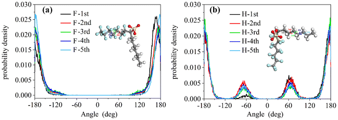
We calculated the torsion angles of the F7H7 surfactant molecular fluorine chains and hydrocarbon chains after equilibrium, which can reflect the conformation of surfactant molecules. As shown in Fig. 4, these results suggested that the hydrogen bond on the hierarchical structure leads to the stronger constraint of the fluorocarbon chain and the fluorocarbon chain conformation is more stable than the hydrocarbon chain. Compared with hydrocarbon chains, fluorine chains can form more stable conformations, resulting in better separation of water from CO2. As shown in Fig. 4(a), the torsion angle distribution of the fluorocarbon chain has a single peak at 180° (plus and minus 180° are connected to each other, which is considered to be only one peak), which represents all the twists in the entire configuration. This conformation, characterized by an anti-periplanar arrangement, is considered stable due to its low energy state. In contrast, in addition to the main peak at 180° in Fig. 4(b), the distribution of torsion angles of the hydrocarbon chains exhibits two secondary peaks at ±60°, which indicates the formation of a metastable syncline conformation for the hydrocarbon chains. Combining the characteristics of hydrogen bond appearance in Fig. 3(b), almost all the hydrogen bonds to the micellar core of water, headgroup, and surfactant fluorine are to the fluorine on the first CF2 starting from sulfur. This shows that the hydrogen bonds will limit the movement of the fluorocarbon chain but will not affect the outer tail conformation, so the outer tail conformation can easily form a stable anti-encircling planar conformation. In contrast, they have minimal influence on the conformation of the hydrocarbon chains, allowing the tail chains to move freely, forming a syncline conformation. This steric effect caused by hydrogen-bonding constraints may be one of the most critical effects leading to the CO2-philic properties of fluorocarbon chains. To isolate the influence of hydrocarbon chains and observe in detail how hydrogen bonds affect the conformation of fluorocarbon chains, we conducted simulations using the PFPE surfactant pre-assembly model, which consists solely of perfluorinated chains in a water/CO2 mixed system.
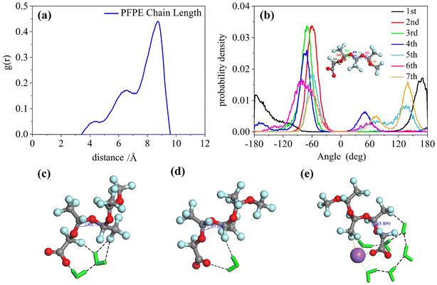
Unlike the single peak of the F7H7 surfactant, the chain length distribution of the PFPE surfactant is shown in three peaks at 4.4 Å, 6.5 Å, and 8.7 Å in Fig. 5(a). Although the range of chain length distribution is wide for both surfactants, the presence of more peaks in the PFPE surfactant chain suggests that PFPE forms specific conformations, rather than flexible ones like F7H7. To determine the conformation of the PFPE surfactant, the torsion angle distributions were performed in Fig. 5(b). The second, third, and fourth torsion angles are mostly 60° implying the synclinal conformation is formed, which is distinct from the most stable anti-periplanar conformation of the first torsion angle. However, the fifth and sixth torsion angles are even performed with gauche defects at 120° (anticlinal confirmation). These different conformations result in different constraints on each fluoride atom in CF2, leading to a restrained surfactant tail in a determined conformation to separate CO2 and water. To provide evidence for the presence of hydrogen bonds between water molecules and PFPE molecules, we conducted calculations of the radial distribution function (RDF) between specific atoms and the time evolution of the number of bonds in the PFPE surfactant molecule (Fig. S3†). Furthermore, we selected and presented representative conformations in Fig. 5, highlighting the existence of hydrogen bonds in these configurations. Fig. 5(c) and (d) illustrate how water provides hydrogen bond donors that connect surfactant headgroups and tails (hydrogen bond acceptors) and restrict the conformation of the surfactant tail at the third torsion angle. In addition to the water acting as a coordinating molecule connected by metal ions as a “bridge”, the fluorine in the surfactant tail also performs coordination phenomenon, which provides another way to constrain the surfactant conformation as shown in Fig. 5(e). The fluorine on the surfactant tail will form hydrogen bonds with the water molecules and due to the hydrogen bonds, the water will be attracted to the fluorine and therefore not interact with CO2. This helps to restrict the conformation of the surfactant, which prevents CO2 from coming into contact with water. Ultimately, the steric effect arising from these interactions leads to the development of CO2-philic behavior in the surfactant. In addition, previous studies using quantum chemical methods have shown that81 fluorine with a high negative charge (−0.26, different from hydrogen's 0.09) could be forming a coordination interaction similar to water molecules and play a role similar to hydrogen bonding to cause CO2-philicity. Studies have shown that these interactions binding conformation of surfactants were weaker than bond intramolecular interactions but stronger than normal non-bonding intermolecular interactions. Here they are referred to as link interactions. This kind of interaction would also impact the CO2-philicity of surfactant. This steric effect caused by hydrogen bond constraints may be one of the critical impacts that lead to the fluorocarbon chain's CO2-philic property. Compared to the F7H7 fluorocarbon's straight conformation (Fig. 3b), the conformations of the PFPE surfactant (Fig. 5(c)–(e)) are curled, which is attributed to linking interactions at different positions of the surfactant tail. In the F7H7 surfactant system, the hydrogen bonds were formed at surfactant headgroups or CF2 groups connected with headgroups because of the F7H7 surfactant hydrocarbon chain steric effect such that link interaction cannot affect the tail after the CF2 group and every torsion angle at the F7H7 surfactant fluorocarbon chain formed anti-periplanar conformation and then restrained the F7H7 surfactant fluorocarbon chain as straight conformation. However, in the PFPE surfactant system (a single chain surfactant known for its typically large FFV, making it difficult to separate water/CO2 and form W/C reverse microemulsion), hydrogen bonds were formed at the surfactant headgroups and the fluoromethyl groups (mostly on the first or second fluoromethyl groups near to the headgroups). In these locations, these hydrogen bonds induced a curled shape in the PFPE surfactant chains by limiting the third and fourth torsion angles in the PFPE surfactant's primary chain to the metastable synclinal conformation. This curled effect was able to increase the percentage of surfactant coverage and this curled structure is stable and difficult to change because of the hydrogen bonding interactions or coordinating interactions restraining surfactant conformation. This phenomenon could effectively separate the water phase and CO2 phase and enhance microemulsion stability. From this phenomenon we can infer that the location of hydrogen bond formation played a significant role in determining the CO2-philic nature of the surfactant, with closer proximity to the tail resulting in stronger restraint on surfactant conformation, facilitating the separation of water and CO2 phases. This explains why this single-chain surfactant (PFPE) was able to form microemulsions in the SC-CO2 phase. Existing studies have shown that fluorination at the surfactant tail terminal group is a key factor determining the ability of the surfactant to effectively stabilize.27,30,82,83 Therefore, di-HCF4, a double-tailed surfactant fluorinated on the surfactant tail group, was investigated.
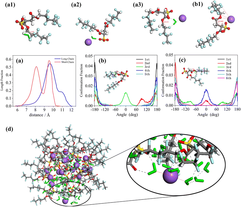
The chain length distribution as well as conformational analysis of the equilibrated di-HCF4 surfactant are shown in Fig. 6. Fig. 6(a) illustrates the chain length distribution of the two chains of the di-HCF4 surfactant, revealing sharp and narrow peaks for both short and long chains. The short chain exhibits two distinct peaks, indicating a more coiled conformation compared to the long chain, which has a single peak. The torsion angle distributions of the short chains (Fig. 6(b)) and long chains (Fig. 6(c)) provide detailed insights into their conformations. Observing the distribution of torsion angles, it is found that almost all torsion angles are distributed around 180°, except for the second and third twists on the short chain and the third and fourth twists on the long chain (equivalent to the second and third torsion). Here, the third torsion angle on the short chain is called the middle torsion angle. There are two peaks at 0° and 180° in the middle torsion angle, which represent two different conformations of the anti-wrapped conformation and the cis-wrapped conformation. There is a significant difference between this and the structure image before the surfactant forms reverse micelles (Fig. S6†). The middle torsion angle distribution of the long chain is unevenly distributed at 0°, which is due to the difference in the chain length distribution of the surfactant due to the two conformational distributions of the middle torsion angle of the surfactant chain. These results suggest that short-chain conformations are more defined than long chains. The radial distribution function (RDF) analysis between water molecules and di-CHF4 molecules (Fig. S4†) provides evidence supporting the formation of hydrogen bonds between water molecules, Na ions, and the active agent molecules. Molecular models of torsion angles formed under hydrogen bonding are shown in Fig. 6(a1) and (a2), which produce the same effect despite differences in the intermediate torsion angles of these conformations (0° in Fig. 6(a1) and 180° in Fig. 6(a2)), that is, they confine the tail near the core with a specific conformation and then stabilize the microemulsion, as we discussed above. In addition, the fluorine coordination between the cation and the tail of the surfactant (as shown in Fig. 6(b1)) also limits the formation of a definite conformation of the surfactant, which is another part of the reason for the 0° twist angle in the middle of the long chain and the sharp and narrower peaks in both chains. The atomic structure in this case, as shown in Fig. 6(a3), exhibits a twist angle of approximately 90°at the third (or second in the short chain) twist angle in the long chains, and almost all of this conformation occurs at the exposed interface (dominating in Fig. 6(b) and (c)). In summary, by integrating various analytical results, including chain length distribution, conformational analysis, torsion angle, RDF analysis, and molecular coordination effects, we found that when the surfactant molecules form reverse micelles, the tail chains will be twisted and bent to different degrees, forming a specific conformation on the surface of the water core. The atoms on the bent tail chain will form hydrogen bonds with water molecules and cations. The existence of hydrogen bonds stabilizes the specific conformation of the tail chain bending, which means that di-HCF4 can form stable reverse micelles.
The results reveal that di-HCF4 surfactants can form stable reverse micelles with a spherical structure, which is consistent with the experimental observations.84,85 This shows that the di-HCF4 surfactant structure is indeed ideal for forming reverse micelles. Compared with perfluorinated tail surfactants such as F7H7 and PFPE, di-HCF4 surfactants limit the conformational flexibility of the surfactant only through the fluorination of the surfactant tail end groups, resulting in a more curved conformation at the intermediate torsion angle. This restriction is likely due to the presence of water molecules and cations, which enhance surfactant coverage and micelle stability. This is similar to the discussion about the differences between fluorocarbon and hydrocarbon chains in F7H7 surfactants demonstrating the effectiveness of fluorination at the surfactant tail terminal group, while perfluorination is ineffective and wasteful. Considering the toxicity and cost associated with fluorocarbon surfactants, a practical alternative is to use a group that can form hydrogen bonds with water molecules to replace fluorine at the surfactant tail terminal. We focused on investigating the preassembly behavior of AOK surfactants in the SC-CO2 system, which are analogs of AOT surfactants. AOK surfactants consist of two hydrocarbon chains and feature an additional carbonyl group at the tail, eliminating the presence of fluorine.
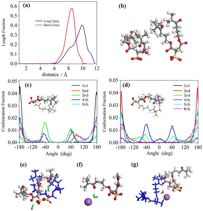
By comparing the length distributions of the short and long chains of AOK surfactants in Fig. 7(a), it was found that the long chains were more widely distributed and thinner than the short chains, although they all exhibited single, sharp, and narrow peaks. This indicates a more defined conformation of the short chains, similar to that observed in the conformational distribution of the di-HCF4 surfactant. Such a curved conformation could improve the coverage of surfactants because of the shorter conformation of surfactants in the reverse microemulsion system which was shown in Fig. 7(b). Both short chains and long chains of the AOK surfactant's conformational distributions were shown in Fig. 7(c) and (d), where most of the torsion angles distributions were performed at only one peak in the 0° (except for the third and fourth torsion angle in the short chains or the fourth and fifth torsion angle in the long chains what we called middle torsion angle just like di-HCF4 surfactant). These middle torsion angles are shown as two peaks around 0° and 60° as a synclinal conformation (mainly) and anti-periplanar conformation (secondarily). These results are consistent with the images we observed for the typical conformations of surfactants in the equilibrated microemulsion system, as shown in Fig. 7(e)–(g). Also, the radial distribution functions (RDF) are calculated to analyze the interactions between internal water molecules and surfactant carbonyl groups, and between water molecules and sodium ions (Fig. S5†). The presence of distinct peaks in RDF is one of the reasons for the existence of hydrogen bonds between these molecular entities. Through analyzing these typical conformations, we discovered that the hydrogen bonding and hydration were linked to the surfactant carbonyl and inner water molecules and restrained the surfactant with the synclinal conformation of the curved chain structure thus stabilizing the reverse micelles of surfactant. Furthermore, we also found that water molecules could link the oxygen atoms of the surfactant headgroups and the oxygen atoms of carbonyl groups near the headgroups. This interaction stabilizes the conformation of short chains, resulting in a straighter configuration. This explains why the length distributions of surfactant chains exhibit sharper peaks for the short chains.
Compared with fluorine-containing di-HCF4 surfactants, we found that surfactants without fluorine on the surface can also form metastable structures under the constraints of hydrogen bonds. The significant difference between the di-HCF4 surfactant and AOK surfactant lies in the fluorine content at the terminal. While di-HCF4 has multiple fluorine atoms, the AOK surfactant only has one carbonyl group at the terminal. This disparity affects the properties of the AOK surfactant, making it challenging to achieve the same performance as di-HCF4. However, despite this difference, the AOK surfactant exhibits similarities with di-HCF4, including comparable length distributions, the same restriction method of water molecule restriction, and even certain conformations of surfactant chains. This provides more evidence affirming our conclusions that carbonylation at the surfactant tail terminal group is effective and that fluorine-substitution by carbonyl groups or other groups capable of forming hydrogen bonds is a feasible method for designing hydrocarbon chain surfactants.
4 Summary and conclusions
Molecular dynamics simulations of four typical CO2-philic surfactant preassembly models of water–surfactant–scCO2 reveal the presence of reverse micelles in supercritical carbon dioxide. These findings demonstrate that nanometer-sized spherical water droplets exist stably in the polar core of surfactant aggregates, which is consistent with the experimental results of previous researchers.Steric effects are discussed in detail by studying the conformational determinants in surfactant reverse micellar systems and specific conformations characterized by length and torsion angle distributions. Our results suggest that the fluorocarbon chains of surfactants can form hydrogen bonds to constrain the conformation of surfactants, thereby forming stable micelles to separate carbon dioxide and water phases. The location of the hydrogen bond formed on the surfactant proves to also be a very important factor in determining micelle stability with hydrogen bond formation at the surfactant chain terminal favouring restriction of surfactant conformations as curved conformations. This will increase the area occupied by the surfactants within the micelles and therefore result in stronger separation. Cations and water molecules can form hydrogen bonds and hydration with head groups, tail groups, and other water molecules to stabilize the micellar structure and promote the formation of hydrogen bonds, which play a role in regulating the stability and structure of micelles. Our conclusions are supported by the fact that such a steric effect is one of the most important factors in the stability of reverse micelles. Based on this principle of steric effects, the concept of modifying the carbonyl groups on the surfactant end groups to obtain better coverage and more stable hydrocarbon surfactants on reverse micelles is feasible for designing hydrocarbon surfactants. While existing hydrocarbon surfactants may have limited practical applications, it is foreseeable that with the development of these basic design principles efficient hydrocarbon surfactants will be synthesized in the future.
Conflicts of interest
There are no conflicts of interest to declare.Acknowledgements
M. W. and D. H. are grateful for financial support from the National Natural Science Foundation of China under Grant U2006224, 52308263, 51978352, 52178221, National Key Research and Development project 2022YFE0133800, Shandong Province Natural Science Foundation under Grant ZR2020QE253, ZR2020JQ25, ZR2022YQ55, 2019KJG010, Shandong Provincial Education Department under Grant 2019KJG010, Qingdao Research Program 16-5-1-96-jch, 111 Project TMduracon20220022, Taishan Scholars of Shandong Province under Grant tsqn.201812090, are gratefully acknowledged.References
- J. H. Clark, V. Budarin, F. E. I. Deswarte, J. J. E. Hardy, F. M. Kerton, A. J. Hunt, R. Luque, D. J. Macquarrie, K. Milkowski, A. Rodriguez and others, Green Chem., 2006, 8, 853–860 RSC.
- O. R. Davies, A. L. Lewis, M. J. Whitaker, H. Tai, K. M. Shakesheff and S. M. Howdle, Adv. Drug Delivery Rev., 2008, 60, 373–387 CrossRef CAS.
- J. H. Clark and S. J. Tavener, Org. Process Res. Dev., 2007, 11, 149–155 CrossRef CAS.
- G. S. Talele and H. V. Shahare, in Natural Pharmaceuticals and Green Microbial Technology, Apple Academic Press, 2021, pp. 1–9 Search PubMed.
- Y. Medina-Gonzalez, S. Camy and J.-S. Condoret, ACS Sustainable Chem. Eng., 2014, 2, 2623–2636 CrossRef CAS.
- C. J. Clarke, W.-C. Tu, O. Levers, A. Brohl and J. P. Hallett, Chem. Rev., 2018, 118, 747–800 CrossRef CAS.
- M. Mazzotti, R. Pini and G. Storti, J. Supercrit. Fluids, 2009, 47, 619–627 CrossRef CAS.
- F. M. Orr Jr and J. J. Taber, Science, 1984, 224, 563–569 CrossRef CAS PubMed.
- M. Enayati, E. Heidaryan and B. Mokhtari, in Canadian International Petroleum Conference, 2008 Search PubMed.
- L. W. Holm and V. A. Josendal, J. Pet. Technol., 1974, 26, 1427–1438 CrossRef.
- L. I. U. He, W. Feng, J. Zhang, M. Siwei and D. Yongwei, Shiyou Kantan Yu Kaifa, 2014, 41, 513–519 Search PubMed.
- M. A. Fernø, M. Steinsbø, Ø. Eide, A. Ahmed, K. Ahmed and A. Graue, J. Nat. Gas Sci. Eng., 2015, 27, 1063–1073 CrossRef.
- Q. I. N. Jishun, H. A. N. Haishui and L. I. U. Xiaolei, Shiyou Kantan Yu Kaifa, 2015, 42, 232–240 Search PubMed.
- E. Heidaryan, T. Hatami, M. Rahimi and J. Moghadasi, J. Supercrit. Fluids, 2011, 56, 144–151 CrossRef CAS.
- A. Pandey, A. S. K. Sinha, K. R. Chaturvedi and T. Sharma, Energy, 2021, 235, 121445 CrossRef CAS.
- J. Eastoe, S. Gold and D. C. Steytler, Langmuir, 2006, 22, 9832–9842 CrossRef CAS PubMed.
- W. Ryoo, S. E. Webber and K. P. Johnston, Ind. Eng. Chem. Res., 2003, 42, 6348–6358 CrossRef CAS.
- M. P. Heitz, C. Carlier, J. deGrazia, K. L. Harrison, K. P. Johnston, T. W. Randolph and F. V. Bright, J. Phys. Chem. B, 1997, 101, 6707–6714 CrossRef CAS.
- J. L. Dickson, P. G. Smith, V. V. Dhanuka, V. Srinivasan, M. T. Stone, P. J. Rossky, J. A. Behles, J. S. Keiper, B. Xu, C. Johnson and others, Ind. Eng. Chem. Res., 2005, 44, 1370–1380 CrossRef CAS.
- J. Eastoe, A. Dupont and D. C. Steytler, Curr. Opin. Colloid Interface Sci., 2003, 8, 267–273 CrossRef CAS.
- J. H. Jun, K. Sawada and M. Ueda, Dyes Pigm., 2004, 61, 17–22 CrossRef CAS.
- M. Sagisaka, D. Koike, S. Yoda, Y. Takebayashi, T. Furuya, A. Yoshizawa, H. Sakai, M. Abe and K. Otake, Langmuir, 2007, 23, 8784–8788 CrossRef CAS.
- M. Hummel, M. Markiewicz, S. Stolte, M. Noisternig, D. E. Braun, T. Gelbrich, U. J. Griesser, G. Partl, B. Naier, K. Wurst and others, Green Chem., 2017, 19, 3225–3237 RSC.
- M. P. Krafft and J. G. Riess, Curr. Opin. Colloid Interface Sci., 2015, 20, 192–212 CrossRef CAS.
- S. Peshoria, D. Nandini, R. K. Tanwar and R. Narang, Environ. Chem. Lett., 2020, 18, 1277–1300 CrossRef CAS.
- J. Eastoe, A. Paul, S. Nave, D. C. Steytler, B. H. Robinson, E. Rumsey, M. Thorpe and R. K. Heenan, J. Am. Chem. Soc., 2001, 123, 988–989 CrossRef CAS PubMed.
- M. Sagisaka, S. Ono, C. James, A. Yoshizawa, A. Mohamed, F. Guittard, R. M. Enick, S. E. Rogers, A. Czajka, C. Hill and others, Colloids Surf., B, 2018, 168, 201–210 CrossRef CAS.
- X. Zhang, J. Q. Pham, N. Ryza, P. F. Green and K. P. Johnston, J. Vac. Sci. Technol., B: Microelectron. Nanometer Struct.--Process., Meas., Phenom., 2004, 22, 818–825 CrossRef CAS.
- J. Liu, B. Han, J. Zhang, G. Li, X. Zhang, J. Wang and B. Dong, Chem. – Eur. J., 2002, 8, 1356–1360 CrossRef CAS.
- A. Mohamed, M. Sagisaka, F. Guittard, S. Cummings, A. Paul, S. E. Rogers, R. K. Heenan, R. Dyer and J. Eastoe, Langmuir, 2011, 27, 10562–10569 CrossRef CAS.
- A. Mohamed, M. Sagisaka, M. Hollamby, S. E. Rogers, R. K. Heenan, R. Dyer and J. Eastoe, Langmuir, 2012, 28, 6299–6306 CrossRef CAS.
- C. A. Moody and J. A. Field, Environ. Sci. Technol., 2000, 34, 3864–3870 CrossRef CAS.
- M. T. Stone, P. G. Smith, S. R. P. da Rocha, P. J. Rossky and K. P. Johnston, J. Phys. Chem. B, 2004, 108, 1962–1966 CrossRef CAS.
- J. Liu, Z. Shervani, P. Raveendran and Y. Ikushima, J. Supercrit. Fluids, 2005, 33, 121–130 CrossRef CAS.
- S. R. P. Da Rocha, K. L. Harrison and K. P. Johnston, Langmuir, 1999, 15, 419–428 CrossRef.
- S. S. Adkins, D. Gohil, J. L. Dickson, S. E. Webber and K. P. Johnston, Phys. Chem. Chem. Phys., 2007, 9, 6333–6343 RSC.
- A. Mohamed, T. Ardyani, S. A. Bakar, M. Sagisaka, S. Ono, T. Narumi, M. Kubota, P. Brown and J. Eastoe, J. Supercrit. Fluids, 2016, 116, 148–154 CrossRef CAS.
- Y. Zheng, S. Herbers, Q. Gou, W. Caminati and J.-U. Grabow, J. Phys. Chem. Lett., 2021, 12, 3907–3913 CrossRef CAS PubMed.
- D. W. Arnold, S. E. Bradforth, E. H. Kim and D. M. Neumark, J. Chem. Phys., 1995, 102, 3493–3509 CrossRef CAS.
- D. Quiñonero, C. Garau, C. Rotger, A. Frontera, P. Ballester, A. Costa and P. M. Deyà, Angew. Chem., 2002, 114, 3539–3542 CrossRef.
- P. Raveendran and S. L. Wallen, J. Am. Chem. Soc., 2002, 124, 12590–12599 CrossRef PubMed.
- S. G. Kazarian, M. F. Vincent, F. V. Bright, C. L. Liotta and C. A. Eckert, J. Am. Chem. Soc., 1996, 118, 1729–1736 CrossRef CAS.
- M. L. O'Neill, Q. Cao, M. Fang, K. P. Johnston, S. P. Wilkinson, C. D. Smith, J. L. Kerschner and S. H. Jureller, Ind. Eng. Chem. Res., 1998, 37, 3067–3079 CrossRef.
- T. Sarbu, T. Styranec and E. J. Beckman, Nature, 2000, 405, 165–168 CrossRef CAS PubMed.
- P. Raveendran and S. L. Wallen, J. Am. Chem. Soc., 2002, 124, 7274–7275 CrossRef CAS PubMed.
- P. Raveendran and S. L. Wallen, J. Phys. Chem. B, 2003, 107, 1473–1477 CrossRef CAS.
- M. T. Stone, S. R. P. da Rocha, P. J. Rossky and K. P. Johnston, J. Phys. Chem. B, 2003, 107, 10185–10192 CrossRef CAS.
- T. A. Hoefling, R. M. Enick and E. J. Beckman, J. Phys. Chem., 1991, 95, 7127–7129 CrossRef CAS.
- H. M. Woods, M. M. C. G. Silva, C. Nouvel, K. M. Shakesheff and S. M. Howdle, J. Mater. Chem., 2004, 14, 1663–1678 RSC.
- L. Bao, S. Fang, D. Hu, Y. Zong, L. Zhao, W. Yuan and T. Liu, J. Supercrit. Fluids, 2018, 133, 163–170 CrossRef CAS.
- M. Sagisaka, T. Narumi, M. Niwase, S. Narita, A. Ohata, C. James, A. Yoshizawa, E. de Givenchy, F. Guittard, S. Alexander and others, Langmuir, 2014, 30, 6057–6063 CrossRef CAS.
- S. Alexander, G. N. Smith, C. James, S. E. Rogers, F. Guittard, M. Sagisaka and J. Eastoe, Langmuir, 2014, 30, 3413–3421 CrossRef CAS PubMed.
- A. Czajka, C. Hill, J. Peach, J. C. Pegg, I. Grillo, F. Guittard, S. E. Rogers, M. Sagisaka and J. Eastoe, Phys. Chem. Chem. Phys., 2017, 19, 23869–23877 RSC.
- M. J. Hollamby, K. Trickett, A. Mohamed, S. Cummings, R. F. Tabor, O. Myakonkaya, S. Gold, S. Rogers, R. K. Heenan and J. Eastoe, Angew. Chem., 2009, 121, 5093–5095 CrossRef.
- M. Wang, S. Wu, P. Wang, B. Dong, M. Ma, Z. Wang, J. Zhong, H. Li and D. Hou, Mater. Struct., 2023, 56(2), 35 CrossRef CAS.
- B. H. Hutton, J. M. Perera, F. Grieser and G. W. Stevens, Colloids Surf., A, 1999, 146, 227–241 CrossRef CAS.
- S. Senapati and M. L. Berkowitz, J. Phys. Chem. B, 2003, 107, 12906–12916 CrossRef CAS.
- H. Sun, P. Ren and J. R. Fried, Comput. Theor. Polym. Sci., 1998, 8, 229–246 CrossRef CAS.
- A. L. Rohl, M. Moret, W. Kaminsky, K. Claborn, J. J. McKinnon and B. Kahr, Cryst. Growth Des., 2008, 8, 4517–4525 CrossRef CAS.
- H. Sun, J. Phys. Chem. B, 1998, 102, 7338–7364 CrossRef CAS.
- J. Yang, Y. Ren, A. Tian and H. Sun, J. Phys. Chem. B, 2000, 104, 4951–4957 CrossRef CAS.
- A. V. Savin and M. A. Mazo, Phys. E, 2020, 118, 113937 CrossRef CAS.
- E. D. Skouras, V. N. Burganos and A. C. Payatakes, J. Chem. Phys., 2001, 114, 545–552 CrossRef CAS.
- X. Wu, R. J. Moon and A. Martini, Cellulose, 2013, 20, 43–55 CrossRef CAS.
- I. M. de Arenaza, E. Meaurio, B. Coto and J.-R. Sarasua, Polymer, 2010, 51, 4431–4438 CrossRef.
- C. Li and A. Strachan, Polymer, 2010, 51, 6058–6070 CrossRef CAS.
- P. Mark and L. Nilsson, J. Phys. Chem. A, 2001, 105, 9954–9960 CrossRef CAS.
- J. Zielkiewicz, J. Chem. Phys., 2005, 123, 104501 CrossRef PubMed.
- J. G. Harris and K. H. Yung, J. Phys. Chem., 1995, 99, 12021–12024 CrossRef CAS.
- S. R. P. da Rocha, K. P. Johnston, R. E. Westacott and P. J. Rossky, J. Phys. Chem. B, 2001, 105, 12092–12104 CrossRef CAS.
- S. Senapati, J. S. Keiper, J. M. DeSimone, G. D. Wignall, Y. B. Melnichenko, H. Frielinghaus and M. L. Berkowitz, Langmuir, 2002, 18, 7371–7376 CrossRef CAS.
- S. Mohammed and G. A. Mansoori, J. Mol. Liq., 2018, 263, 268–273 CrossRef CAS.
- M. KRV, C. Wang, A. Masunov and S. Vasu, in AIAA SCITECH 2022 Forum, 2022, p. 2060 Search PubMed.
- B. Liu, J. Shi, M. Wang, J. Zhang, B. Sun, Y. Shen and X. Sun, J. Supercrit. Fluids, 2016, 111, 171–178 CrossRef CAS.
- O. A. Moultos, G. A. Orozco, I. N. Tsimpanogiannis, A. Z. Panagiotopoulos and I. G. Economou, Mol. Phys., 2015, 113, 2805–2814 CrossRef CAS.
- L. Zhao, S. Lin, J. D. Mendenhall, P. K. Yuet and D. Blankschtein, J. Phys. Chem. B, 2011, 115, 6076–6087 CrossRef CAS PubMed.
- Y. Ling, S. Yao, Y. Chen, D. Hu, Z. Xi and L. Zhao, J. Supercrit. Fluids, 2022, 180, 105424 CrossRef CAS.
- P. P. Ewald, Ann. Phys., 1921, 369, 253–287 CrossRef.
- W. Humphrey, A. Dalke and K. Schulten, J. Mol. Graphics, 1996, 14, 33–38 CrossRef CAS PubMed.
- M. Wang, K. Zhang, X. Ji, P. Wang, H. Ma, J. Zhang and D. Hou, Constr. Build. Mater., 2022, 316, 125800 CrossRef CAS.
- Y. Zhang, J. Li, Z. Yin, J. Zhang, W. Guo and M. Wang, Langmuir, 2020, 36, 15352–15361 CrossRef CAS PubMed.
- J. Eastoe, A. Paul, A. Rankin, R. Wat, J. Penfold and J. R. P. Webster, Langmuir, 2001, 17, 7873–7878 CrossRef CAS.
- M. Sagisaka, S. Iwama, S. Ono, A. Yoshizawa, A. Mohamed, S. Cummings, C. Yan, C. James, S. E. Rogers, R. K. Heenan and others, Langmuir, 2013, 29, 7618–7628 CrossRef CAS PubMed.
- S. R. P. da Rocha and K. P. Johnston, Langmuir, 2000, 16, 3690–3695 CrossRef CAS.
- S. Cummings, K. Trickett, R. Enick and J. Eastoe, Phys. Chem. Chem. Phys., 2011, 13, 1276–1289 RSC.
Footnote |
| † Electronic supplementary information (ESI) available. See DOI: https://doi.org/10.1039/d3me00115f |
| This journal is © The Royal Society of Chemistry 2024 |


![[double bond, length as m-dash]](https://www.rsc.org/images/entities/char_e001.gif) O)–C(C
O)–C(C