
 Open Access Article
 This Open Access Article is licensed under a
 Creative Commons Attribution 3.0 Unported Licence
A bio-based thermoplastic polyurethane with triple self-healing action for wearable technology and smart textiles†
Thomas
Griggs
a,
Jubair
Ahmed
b,
Hamta
Majd
b,
Mohan
Edirisinghe
b and
Biqiong
Chen
 *a
*a
aSchool of Mechanical and Aerospace Engineering, Queen's University Belfast, Stranmillis Road, Belfast BT9 5AH, UK. E-mail: b.chen@qub.ac.uk
bDepartment of Mechanical Engineering, University College London, Torrington Place, London WC1E 7JE, UK
First published on 17th June 2024
Abstract
Self-healing bio-based polymers are an emerging class of materials with promise in both limiting the use of non-renewable monomers in polymer production and increasing the life span of materials through the healing of damage that would otherwise cause the material to fail. This study reports a novel biobased thermoplastic polyurethane (TPU) with triple self-healing action, showing excellent stretchability and self-healing behaviour. The effect of hard segment percentage on the mechanical, thermal, and hydroscopic properties was investigated. The optimised TPU exhibits an elongation at break of 1871%, an ultimate tensile strength (UTS) of 0.36 MPa and a Shore A hardness of 40. The self-healing efficiencies for elongation at break and UTS reach above 90% after only three hours under ambient conditions due to triple action. The TPU shows skin-mimicking mechanical properties, and hydrophobicity, and acts as a stretchable, self-healing substrate for printing conductive circuits, making it a promising candidate for use in stretchable conductors, wearable devices and electronic skin. This bio-based self-healing polymer also shows high processibility into uniformly sized fibres, allowing use in smart elastic textiles.
Introduction
Thermoplastic polyurethanes (TPUs) are materials of current interest in a wide range of applications, including but not limited to surface coating,1 medical tubing,2 automotive,3 and stretchable electronics.4 They are produced utilising a range of diisocyanates, diols and chain extenders, resulting in a segmented material that has a remarkable ability to tailor the final polymer properties for specific applications. However, TPUs are generally produced using petrochemical precursors that are not renewable and show detrimental environmental impact.Bio-based TPUs are being produced to counteract these negatives. Recently, the introduction of bio-based components made through using feedstock stemming from plants, e.g., lignin5 or bacterial fermentation,6 has helped to decrease the environmental footprint of the polymers.
Conventional TPUs are generally susceptible to damage and scratches during use which can lead to catastrophic failure, limiting their operating lifetime.7 A way to counteract these types of damage is through the incorporation of self-healing capabilities into the material,8 which allows for rapid healing of any damage, prolonging its lifespan9 and lowering its ecological footprint. Initial pathways to fulfil self-healing involved the addition of capsules or fillers within the polymer; however, this created high-stress concentration areas, which increased the likelihood of failure.10 Further developments now utilise dynamic reversible bonds, which negate the use of foreign objects within the polymer, and provide the ability of multiple healing instances.10
Different dynamic bonds currently used include Diels–Alder interactions,11 metal–ligand interactions,12 and boron–oxygen dative bonding.13 A promising bond also utilised for healing is the disulphide bond, which readily undergoes disulphide exchange at moderate temperatures. Aliphatic disulphide bonds are commonly used; however, these require an external stimulus such as elevated temperatures, causing higher energy utilisation. Several TPUs in the literature have required healing for 3 h at 120 °C,14 6 h at 60 °C,15 or 4 h at 70 °C16 to achieve high elongation recovery. Other stimuli, such as ultraviolet (UV), can be used and show full recovery after 6 hours of exposure.17
Hydrogen bonding has also been used to prepare self-healing polymers; these require either multifunctional groups with heavily hydrogen-bonded structures,18 or the presence of other dynamic bonds to reach high levels of self-healing.15 Dangling chains within the polymer structure have also been used to help increase the levels of self-healing through the addition of high amounts of van der Waals forces. Such an approach has been seen to have potential for relatively high levels of self-healing.19
In this work, novel bio-based self-healing TPUs are reported, synthesised in one-step step-growth polymerisation with alicyclic isophorone diisocyanate (IPDI), 100% bio-based Pripol 2033, and hydroxyethyl disulphide (HEDS). We hypothesised that three dynamic features of the polymer, namely, disulphide bonding, hydrogen bonding, and van der Waals forces, would allow for excellent synergistic ambient temperature self-healing. HEDS would allow for the addition of the dynamic disulphide bond, capable of providing good ambient temperature self-healing. Pripol 2033 was chosen as a diol as a shorter chain diol would allow for a higher concentration of urethane linkages and therefore a higher concentration of hydrogen bonding, and the presence of dangling chains in the structure would provide a high level of van der Waals forces acting to further improve the self-healing capabilities. The structure and properties of these bio-based self-healing materials were investigated, and their potential applications in stretchable electronics, e-skins/wearable devices, and textiles were explored.
Experimental
Materials
Dimethyl formamide (DMF), dibutyltin dilaurate (DBTDL), HEDS, hexanediol (HDO), IPDI, deuterated chloroform (CDCl3), tetramethylsilane, chloroform, and tetrahydrofuran (THF) containing 2.0% v/v triethylamine and 0.05% w/v BHT inhibitor, all analytical grade, were purchased from Sigma-Aldrich (Gillingham, UK). Diol, Pripol 2033, was provided by Cargill (Gouda, the Netherlands). All chemicals were used as received.Synthesis of bio-based TPUs
TPUs were synthesised in a glass vial purged with nitrogen. Pripol 2033 and HEDS were added to a vial with 0.05 wt% DBDTL and 300 wt% DMF and mixed for 30 min at 60 °C using a hotplate magnetic stirrer. IPDI was then added and allowed to react for 3 hours at 60 °C, before being poured into a mould with a 10 cm diameter and dried on a hot plate set to 100 °C to evaporate the solvent. This was followed by overnight drying in a convection oven at 40 °C.Three TPUs were synthesised with varying hard segment (IPDI) weight percentages, 35% (P35), 40% (P40) and 45% (P45), and an NCO![[thin space (1/6-em)]](https://www.rsc.org/images/entities/char_2009.gif) :OH molar ratio of 1:1 (by fixing the molar number of Pripol 2033 and varying the molar number of HEDS). P40-H was also produced, utilising HDO instead of HEDS to replace the disulphide bonds with a carbon–carbon bond to understand the impact of dynamic bonds on healing.
:OH molar ratio of 1:1 (by fixing the molar number of Pripol 2033 and varying the molar number of HEDS). P40-H was also produced, utilising HDO instead of HEDS to replace the disulphide bonds with a carbon–carbon bond to understand the impact of dynamic bonds on healing.
Characterisation
Fourier transform infrared (FTIR) spectroscopy was performed using a PerkinElmer Spectrum 100, with attenuated total reflectance mode in the region of 4000–650 cm−1. 16 scans were done with a resolution of 4 cm−1.Nuclear magnetic resonance (NMR) 1H NMR and 13C NMR were performed on a Bruker Avance III HD 600 MHz NMR instrument, with a 5 mm PABBO BB probe. CDCl3 was used as the solvent. Tetramethylsilane was used as the internal standard for 1H NMR. The number of scans were 64 and 4096 for 1H NMR and 13C NMR, respectively.
Gel permeation chromatography (GPC) was performed using an Agilent 1260 Infinity II GPC with Agilent GPC/SEC software and 2 × PLgel 5 μm MIXED-C columns (polystyrene-divinylbenzene (PS/DVB), as well as a PLgel 5 μm guard column at 35 °C and a flow rate of 1.0 mL min−1. The eluent used was THF containing 2.0% v/v triethylamine and 0.05% w/v BHT inhibitor. The sample concentration was 3 g ml−1 prepared by mechanical stirring overnight followed by filtering through a 0.45 μm PTFE syringe filter. The GPC was calibrated using 12 × EasiVial PS-H (2 mL) standards, with molecular weights equal to 162, 580, 1210, 4880, 10330, 22790, 75050, 194500, 479200, 885000, 3152000, and 6570000 g mol−1.
Differential scanning calorimetry (DSC) was performed using a TA Discovery DSC25 instrument under nitrogen flow (at a rate of 50 mL min−1) with a heating/cooling rate of 10 °C min−1 at temperatures between −90 °C and 190 °C. Two cycles of heating–cooling were performed, and the second cycle was analysed. Thermal gravimetric analysis (TGA) was carried out on a Netzsch TG 209F1 Libra instrument under a nitrogen flow (at a rate of 50 mL min−1) between 25 °C and 600 °C at a heating rate of 10 °C min−1.
Tensile testing was performed on a Lloyds LRX universal testing machine using a 50 N load cell at room temperature (RT) (≈20 °C) with a crosshead speed of 100 mm min−1 according to ISO-37. A minimum of four (P35/P40) or three (P45) samples were tested. Cyclic tensile testing was carried out to 100% strain on the same machine at a speed of 20 mm min−1 with one-minute rest given between cycles. A hardness test was conducted with Shore A on a Coats Comaco Rubber Hardness Tester in accordance with ISO-868. The specimens had a minimum thickness of 4 mm. Three separate areas of the samples were tested for each composition.
To quantify the mechanical self-healing of the TPUs, the materials were evaluated through a cut-heal process. The specimens were cut completely in half using a scalpel blade and then the two damaged surfaces were placed back together by hand for several seconds, followed by another set or amount of time of further self-healing without force. After a given time, the samples underwent uniaxial tensile testing.
The water contact angle was measured on a Krüss DSA-100. Three different areas of each sample were tested per composition. A smooth area of the sample had a 20 μL droplet of water placed onto the surface. The angle between the droplet and the surface was then measured.
To prepare mechanical and physical testing samples, the TPU materials synthesised were hot pressed at 120 °C for 5 min on a Randoll electrical press to produce rectangular sheets with a thickness of 2 mm. The dumbbell samples for tensile testing were cut from the sheets using a Ray-Ran punch and an ISO 37 type 3 mould, and small disc samples (1 cm diameter) for hardness and contact angle tests were cut using a 10 mm biopsy punch.
Manufacture and characterisation of a stretchable conductor
To prepare the stretchable conductors, rectangular samples of dimensions 10 mm × 40 mm for use in conductivity tests were cut using a cutting press, and the circuits were printed using a Voltero V-One inkjet printer and a silver ink (PerkyPegasus, containing between 70 and 90 wt% silver and a viscosity of 5000 cP) supplied by Voltero. To test the electrical performance under strain, a Lloyd LRX tensile testing machine was utilised to stretch the device to a strain of 300% at a rate of 5 mm min−1, while a Keysight 34470A multimeter was used to record the change in resistance by a two-probe method. Two alligator clips were attached to either side of the printed conductive circuit.Production and characterisation of bio-based TPU fibres
Fibre spinning was carried out using the pressurised gyration method20 to produce bio-based TPU fibres. The polymer was dissolved in chloroform at a concentration of 30 wt% TPU in chloroform, and then spun at 11000 rpm at an applied pressure of 0.1 MPa. Scanning electron microscopy (SEM) was carried out on the produced fibres using a Zeiss Gemini SEM 360, with an operating voltage of 1 kV and a working distance of 6 mm. The average diameter of the fibres was found through 100 fibres being measured at random. To test the tensile properties of the fibres, yarns with a diameter of 0.25 mm were chosen, with five samples tested. A Lloyd LRX was used with a load cell of 50 N and a strain rate of 100 mm min−1.
Results and discussion
Synthesis and chemical structure of TPUs
TPUs based on HEDS, IPDI and Pripol 2033 were synthesised with equimolar –OH and –NCO groups by one-step step-growth polymerisation (Scheme 1). The hard segment weight percentages in the polymer were 35%, 40% and 45%, which were denoted as P35, P40 and P45, respectively. The resulting TPUs were transparent and colourless. | ||
| Scheme 1 Synthesis scheme of TPUs. The structure of Pripol 2033 and TPU is simplified. The TPUs are not block copolymers. | ||
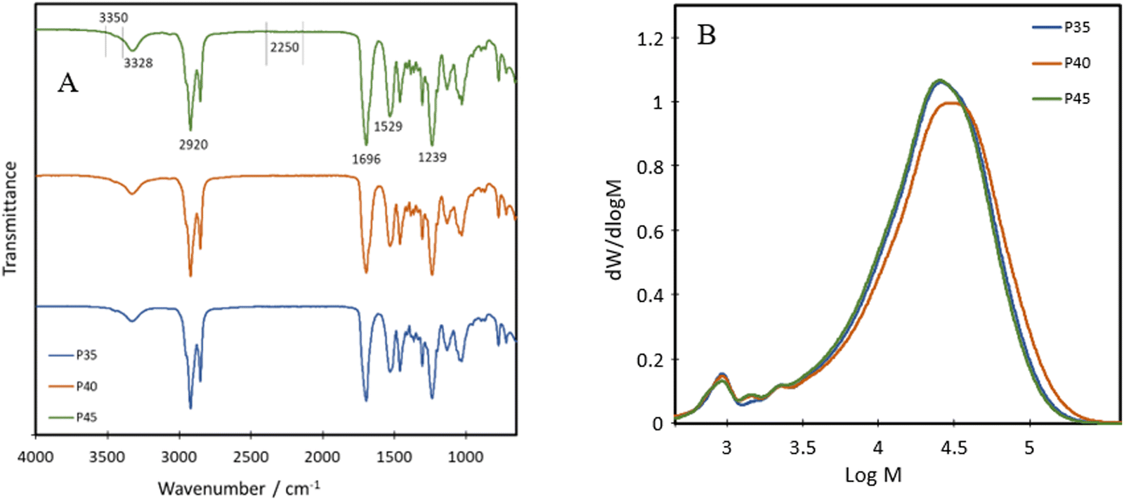
The chemical structure of the bio-based TPU synthesised was first characterised using FTIR, with their spectra being presented in Fig. 1A. The absorption bands at 3328 cm−1, 1529 cm−1 and 1239 cm−1 are attributed to the N–H stretching from amide A, the N–H bending of amide II and the N–H bending of amide III, respectively.21 Other characteristic polyurethane peaks are seen with the C![[double bond, length as m-dash]](https://www.rsc.org/images/entities/char_e001.gif) O stretching absorption band present at 1696 cm−1 while complete reaction and removal of the hazardous isocyanate bonds are confirmed through the absence of an NCO peak at 2250 cm−1,22 with minimal shouldering at 3350 cm−1 correlating with the –OH bond.23 These results confirm the successful formation of polyurethane and the complete reaction of the isocyanate bonds in IPDI. The peak at 3328 cm−1 shows an increase in intensity with increasing hard segment percentage, implying the potential for the highest level of hydrogen bonding within P45, between the neighbouring urethane bonds. The formation of polyurethanes was further investigated using 1H NMR and 13C NMR (Fig. 2). In the 1H NMR spectrum of P40 (Fig. 2A), chemical shifts corresponding to characteristic polyurethane bonds can be seen, namely that of the methylene proton adjacent to –NH at 2.9 ppm.24,25 The methylene proton adjacent to –CO linkage is present at 4 ppm. The –CH3 protons, present at the end of both the dangling chains of the diol and the IPDI, are seen at 1 ppm.26 –CH2 protons produce a chemical shift at 1.3 ppm which is within the polymer backbone.27 The –NH proton, is expected at around 6.5–7 ppm,24,25 however, was absent in the spectra due to its exchangeable nature with deuterium atoms present within the solvent.28 Similar to FTIR, each of the TPUs shows very similar peak positions; however, the relative intensities vary (Fig. S1 and S2, ESI†). With increasing hard segments, both the –NH proton of the urethane bonds and –CH3 protons present on the IPDI show increased intensity. The protons present on the alicyclic IPDI also show increased intensity, while the –CH2 protons of the polymer backbone show a decreased intensity, which can be attributed to the lowered percentage of the diol structure within the polymer. For 13C NMR (Fig. 2B), the molecules that produced chemical shifts are as follows: 13C from the CO linkage present in polyurethane structures is seen at 170 ppm, and methylene groups next to –NH is seen at 38 ppm.2913C capping the non-reactive dangling chains produces the chemical shift at 15 ppm, with the mid-chain methylene groups at 30 ppm.29
O stretching absorption band present at 1696 cm−1 while complete reaction and removal of the hazardous isocyanate bonds are confirmed through the absence of an NCO peak at 2250 cm−1,22 with minimal shouldering at 3350 cm−1 correlating with the –OH bond.23 These results confirm the successful formation of polyurethane and the complete reaction of the isocyanate bonds in IPDI. The peak at 3328 cm−1 shows an increase in intensity with increasing hard segment percentage, implying the potential for the highest level of hydrogen bonding within P45, between the neighbouring urethane bonds. The formation of polyurethanes was further investigated using 1H NMR and 13C NMR (Fig. 2). In the 1H NMR spectrum of P40 (Fig. 2A), chemical shifts corresponding to characteristic polyurethane bonds can be seen, namely that of the methylene proton adjacent to –NH at 2.9 ppm.24,25 The methylene proton adjacent to –CO linkage is present at 4 ppm. The –CH3 protons, present at the end of both the dangling chains of the diol and the IPDI, are seen at 1 ppm.26 –CH2 protons produce a chemical shift at 1.3 ppm which is within the polymer backbone.27 The –NH proton, is expected at around 6.5–7 ppm,24,25 however, was absent in the spectra due to its exchangeable nature with deuterium atoms present within the solvent.28 Similar to FTIR, each of the TPUs shows very similar peak positions; however, the relative intensities vary (Fig. S1 and S2, ESI†). With increasing hard segments, both the –NH proton of the urethane bonds and –CH3 protons present on the IPDI show increased intensity. The protons present on the alicyclic IPDI also show increased intensity, while the –CH2 protons of the polymer backbone show a decreased intensity, which can be attributed to the lowered percentage of the diol structure within the polymer. For 13C NMR (Fig. 2B), the molecules that produced chemical shifts are as follows: 13C from the CO linkage present in polyurethane structures is seen at 170 ppm, and methylene groups next to –NH is seen at 38 ppm.2913C capping the non-reactive dangling chains produces the chemical shift at 15 ppm, with the mid-chain methylene groups at 30 ppm.29
 | ||
| Fig. 1 (A) FTIR spectra (spectra have been shifted vertically for clarity), and (B) GPC traces of TPUs. | ||
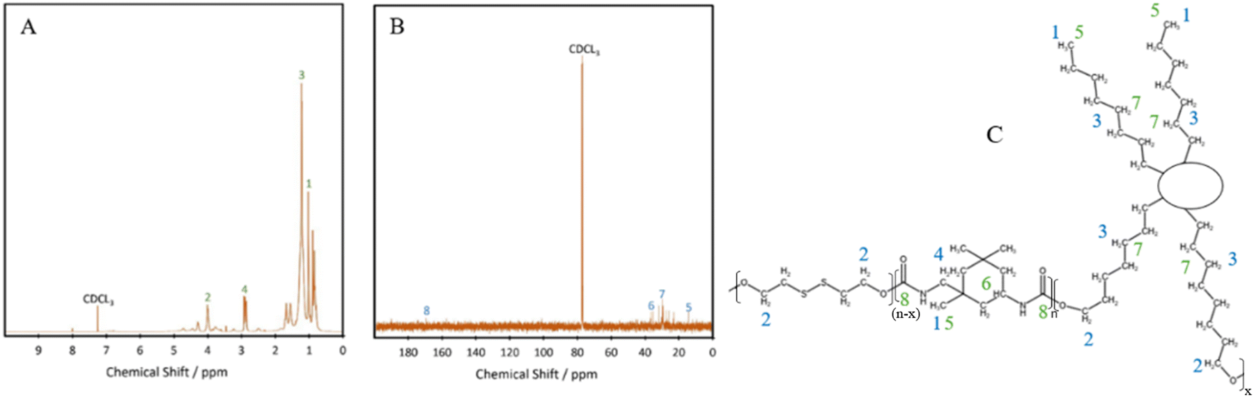 | ||
| Fig. 2 (A) 1H NMR spectra, (B) 13C NMR spectra, and (C) NMR peak designations for P40. | ||
P35, P40 and P45 show weight average molecular weights (![[M with combining macron]](https://www.rsc.org/images/entities/i_char_004d_0304.gif) ws) of 30740, 35580 and 30100 g mol−1 and polydispersity indices (PDIs) of 2.2, 2.0 and 1.9, respectively, obtained from GPC (Fig. 1B). This implies that the polymers have a relatively narrow molecular weight distribution compared to bio-based branched elastomers which have shown values ranging from 3 to 4.19,30 The presence of dangling chains may influence the molecular weights of the various compositions, as their presence in the soft segment would imply that as the hard segment ratio is increased, fewer dangling chains would be present. Despite this, the results suggest that the level of the hard segment has little effect on both the molecular weight and the PDI of the polyurethanes. For all three polymers, there is an additional peak at just under 3 logM, accounting for around 3% oligomers.
ws) of 30740, 35580 and 30100 g mol−1 and polydispersity indices (PDIs) of 2.2, 2.0 and 1.9, respectively, obtained from GPC (Fig. 1B). This implies that the polymers have a relatively narrow molecular weight distribution compared to bio-based branched elastomers which have shown values ranging from 3 to 4.19,30 The presence of dangling chains may influence the molecular weights of the various compositions, as their presence in the soft segment would imply that as the hard segment ratio is increased, fewer dangling chains would be present. Despite this, the results suggest that the level of the hard segment has little effect on both the molecular weight and the PDI of the polyurethanes. For all three polymers, there is an additional peak at just under 3 logM, accounting for around 3% oligomers.
Thermal properties of TPUs
To investigate thermal transitions and thermal stability of the formulations, DSC and TGA were carried out on P35, P40 and P45. The DSC curves show that the produced TPUs are amorphous polymers, as no melting peaks are seen within the range of –60 °C to 190 °C (Fig. 3A). The diol, Pripol 2033, contains two dangling unreactive chains per repeating unit, which hinders the formation of crystalline regions within the polymer chains.19 The diol also shows a short chain length, which is less likely to crystallise.31 The diisocyanate used, IPDI, shows an asymmetric structure, which has been seen to limit crystallinity.32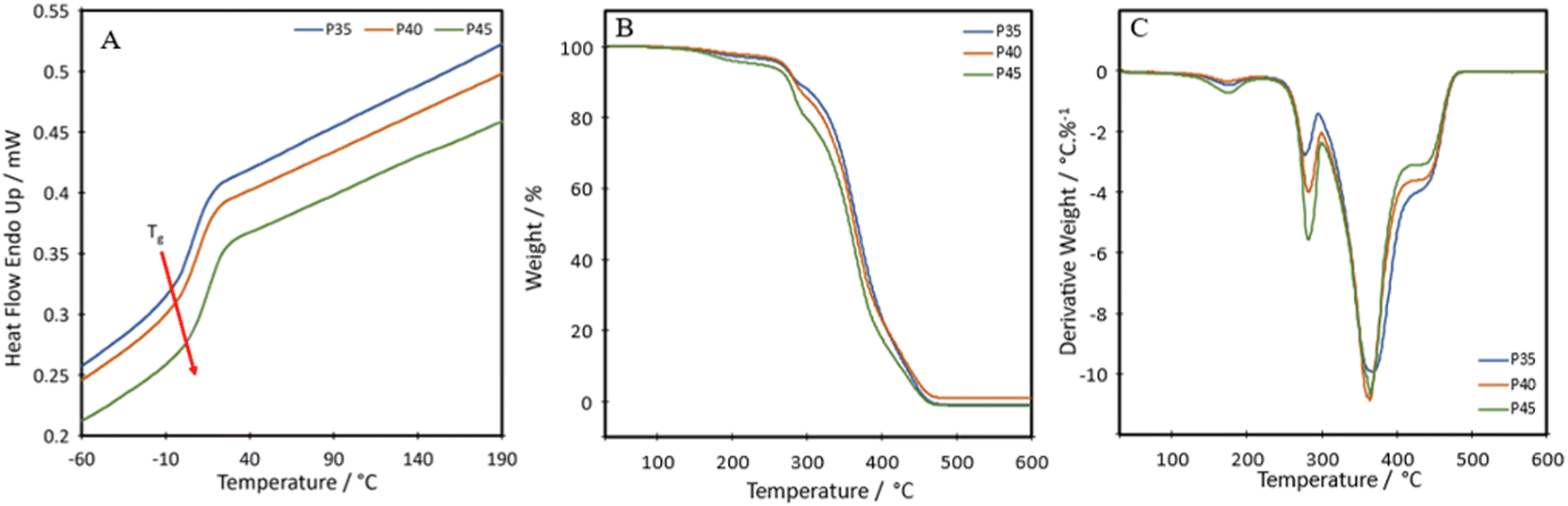 | ||
| Fig. 3 Thermal data of TPUs: (A) DSC, (B) TGA, and (C) DTG thermograms. | ||
The glass transition temperature, Tg, of the synthesised TPUs, determined as the onset of the transition, were −6.6 °C, −3.7 °C and −1.4 °C for P35, P40 and P45, respectively, slightly high compared with other self-healing or bio-based TPUs, which show a Tg value as low as −45 °C.33,34 The short length of the diol increases the Tg value.35 The higher Tg value of the TPUs is not a limitation for self-healing, as the values are lower than RT. The results show an increase in the Tg of the material in relation to the hard segment percentage present. Each TPU showed an initial thermal degradation temperature of 150 °C, which correlates with the breakdown of the urethane bond formed between a primary or secondary alcohol and an isocyanate;36 however, this loss was very small, ranging from 1.7 to 3.8% (Fig. 3B). There were two further steps of degradation, the first at around 250 °C is the hard segment breaking down37 and can be seen from the derivative thermogravimetry (DTG) plot (Fig. 3C). As the hard segment increases, the amount of weight loss in the peak at 250 °C increases correspondingly. The third step, shown by the peak at 350 °C is where the soft segment decomposes.37 The final drop after the plateau at around 410 °C can be attributed to the final breakdown of aromatic components, between 400 °C and 600 °C.38 A char of around 1 wt% remains at 600 °C.
The temperature at which the highest level of degradation occurs (Tpeakd) is determined from the DTG curves to be 368 °C, 364 °C and 364 °C for P35, P40 and P45, respectively. These values are slightly lower than those seen for other bio-based polyurethanes produced with vegetable oil-based diols, with these ranging from around 378 to 394 °C.39,40 It is hypothesised that the slightly reduced degradation temperature could be a side effect of having the disulphide bond present in the chain. A polyurea–urethane containing the disulphide bond produced by Zhang et al. also showed a lowered Tpeakd at around 346 °C.41 The temperatures for 50% weight loss for P35, P40 and P45 are 367 °C, 364 °C and 357 °C, respectively. A difference of 10 °C between P35 and P45 is seen, which stems from the hard segment being less stable and therefore degrading to a greater degree at a lower temperature.42
Mechanical properties
Fig. 4A shows the representative tensile stress–strain curves for P35, P40 and P45. The ultimate tensile strength (UTS), Young's modulus and the elongation at break were measured and are listed in Table 1. Each of the polymers shows distinct linear elastic regions, before plateauing, and then shows a transition in the middle, which can be attributed to the self-healing nature of the polymers.43 As the polymer chains are stretched, the chains first align and the dynamic bonds rupture. If self-healing can occur fast enough, the ruptured dynamic bonds, in this case the disulphide bond, can reform the bond and increase the lifetime of the material.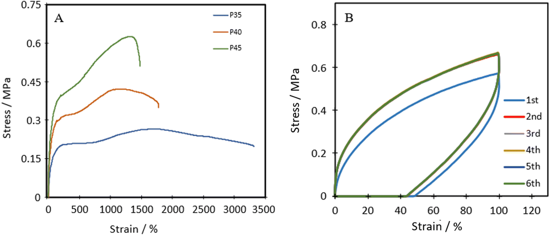 | ||
| Fig. 4 (A) Representative tensile stress–strain plots of TPUs, and (B) cyclic tensile plots of P40 with 1-minute rest between cycles. | ||
| Sample | UTS/MPa | Young's modulus/MPa | Elongation at break/% |
|---|---|---|---|
| P35 | 0.27 ± 0.09 | 0.32 ± 0.04 | 2841 ± 325 |
| P40 | 0.37 ± 0.04 | 0.49 ± 0.08 | 1871 ± 161 |
| P45 | 0.54 ± 0.08 | 0.79 ± 0.12 | 1454 ± 41 |
The Shore A hardness values for P35, P40 and P45 were 35, 40 and 45, respectively, showing increasing hardness with an increase in the hard segment, similar to strength and stiffness.
P40 has a Young's modulus of 0.49 ± 0.08 MPa, which is similar to the Young's modulus of isobutylene isoprene rubber (IIR) ≈0.41 MPa),44 polydimethylsiloxane (PDMS, ≈0.46 MPa)45 and Dragonskin 30 (modulus at 100% strain ≈0.59 MPa).46 Meanwhile, the elongation at break (1871%) of P40 improves compared to the values of IIR (170%), Dragonskin 30 (800%) and PDMS (338%). P40 shows similar Shore A hardness (40) for both PDMS (41–43) and IIR (40). Due to the comparable Young's modulus and hardness, P40 was selected for further cyclic testing.
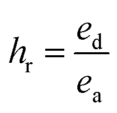
Cyclic tensile stress–strain curves of P40 are shown in Fig. 4B, with six repeated loading–unloading cycles up to 100% strain at a strain rate of 20 mm min−1 with one-minute rest given between cycles. A difference is seen between the first loading curve and all remaining loading curves, showing a lower stress than the remaining cycles. The polymer chains may become more aligned during the initial strain occurrence and may not adopt their original conformation in subsequent cycles, resulting in a higher required force in the remaining cycles.47 Cycles 2–6 show almost identical curves, suggesting P40 has good resilience and shape recovery under the testing conditions. The natural occurrence of hydrogen bonding between the urethane linkages and the van der Waals forces between dangling chains results in many physical crosslinks that contribute to good shape recovery.33 The hysteresis ratio (hr) was calculated using eqn (1) to understand the efficiency of the energy dissipated.
 | (1) |
Self-healing properties
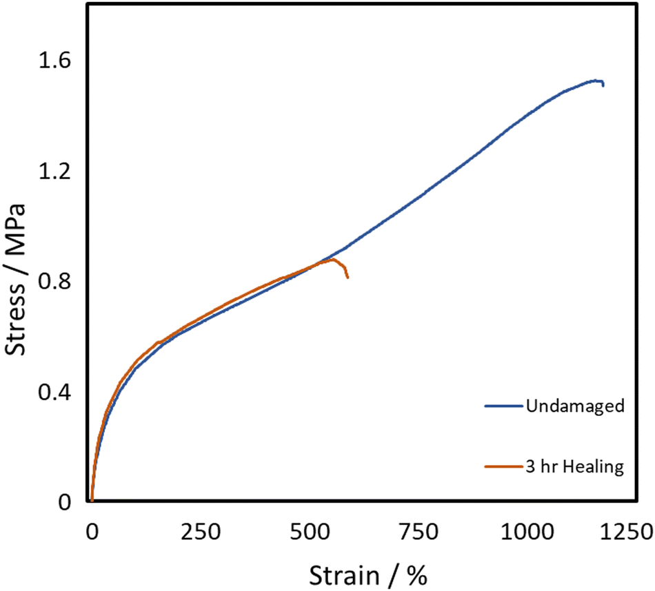
All three of the TPUs reported herein, unlike the above-mentioned commercial elastomers, showed inherent room temperature self-healing capabilities (Fig. 5). Fig. 6 shows the tensile stress–strain plots for the undamaged, the 1 h healed, and the 3 h healed samples for each of the polymers. 20-minute self-healing was additionally carried out on P40 to investigate whether a shorter time period could also provide sufficient self-healing efficiencies as it showed excellent 1-hour healing. Each of the healed samples shows quite similar curves with unique transition in the middle similar to the stress–strain plots in Fig. 4A; however, P35 and P45 fail at much lower elongation. P40 again shows similar curves for each of the healing times, with the UTS increasing with an increase in the self-healing time.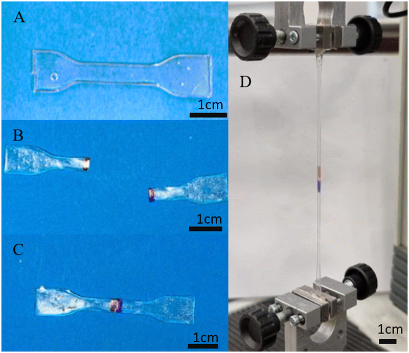 | ||
| Fig. 5 Demonstration of touch-healing capabilities of synthesised P40: (A) original, (B) cut in half, (C) physical touch-healing for 2 h, and (D) healed sample under tensile testing. | ||
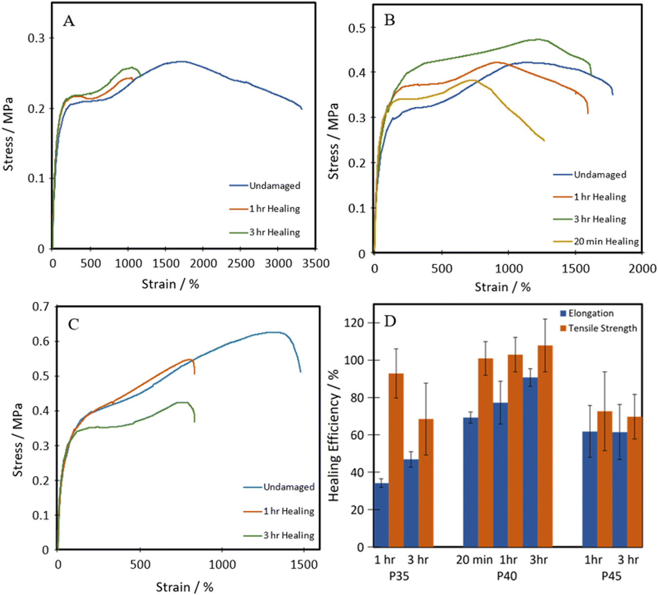 | ||
| Fig. 6 Representative tensile stress–strain plots of healed (A) P35, (B) P40, and (C) P45; (D) self-healing efficiencies of TPUs. | ||
The self-healing efficiency is quantified as a percentage of the mechanical properties achieved compared to the undamaged material. As shown in Fig. 6, the three synthesised TPUs all show some level of RT self-healing, with P40 showing a significant healing efficiency of 69 ± 2% in terms of elongation and 101 ± 3% in terms of UTS after only 20 minutes. After one hour, P35 showed the lowest self-healing efficiency at 34 ± 2% for elongation and 93 ± 13% UTS. This was then followed by 62 ± 13% elongation and 73 ± 20% UTS seen in P45, finally followed by 77 ± 11% and 103 ± 9% in P40. P45 showed no increase in healing with prolonged healing time, while P35 showed a small increase in elongation up to 47 ± 4%. P40 shows improvement in both elongation and UTS healing, reaching high values of 91 ± 4% and 108 ± 14%, respectively, after 3 h healing.
This level of RT self-healing is uncommon amongst polymers utilising the aliphatic disulphide bonds, which generally require long healing times at RT, typically longer than 12 hours, or external stimuli such as heat14–16 or UV exposure,17 to facilitate self-healing. This improvement in the ambient self-healing efficiency for the aliphatic disulphide bond is hypothesised to be partially due to the shorter length of chain extender, which increases the hydrogen bonding density within the polymer, allowing for more dynamic bonds that can facilitate self-healing.51,52 Dangling chains have also been seen to provide polymers with innate self-healing abilities due to their abundant presence of van der Waals forces.19,53
Therefore, the triple action network of the dynamic disulphide bonds, hydrogen bonds and van der Waals forces present in the dangling chains, as illustrated in Scheme 2, helps give these polymers enhanced ambient temperature self-healing. P35 showed the lowest levels of self-healing of the three different compositions. As the dynamic disulphide bond is housed in the chain extender, which P35 contains the least of (due to the lowest amount of hard segment used), the inferior self-healing in P35 is attributed to the lower density of disulphide bonds which plays a significant role in healing efficiency.14,16,41,43 With P45, there are ample disulphide bonds present as a higher amount of chain extenders was used through the increased hard segment. However, chain diffusion is a vital stage in the self-healing process,54 and when this is too low due to the higher chain stiffness, the dynamic bonds cannot reach each other in order to fill the damaged area and heal. Therefore, the lower self-healing properties seen within this polymer can also be attributed to the material being too hard for chain diffusion to occur. Interestingly, the P40 samples that were healed for both one hour and three hours, show a UTS and Young's modulus marginally higher than those of the undamaged sample. It is hypothesised that the healing process instilled a small amount of chain orientation to the damaged area, lowering the level of randomness in the chains. This slight change to chain orientation could also be the cause for the marginal loss in elongation during self-healing.
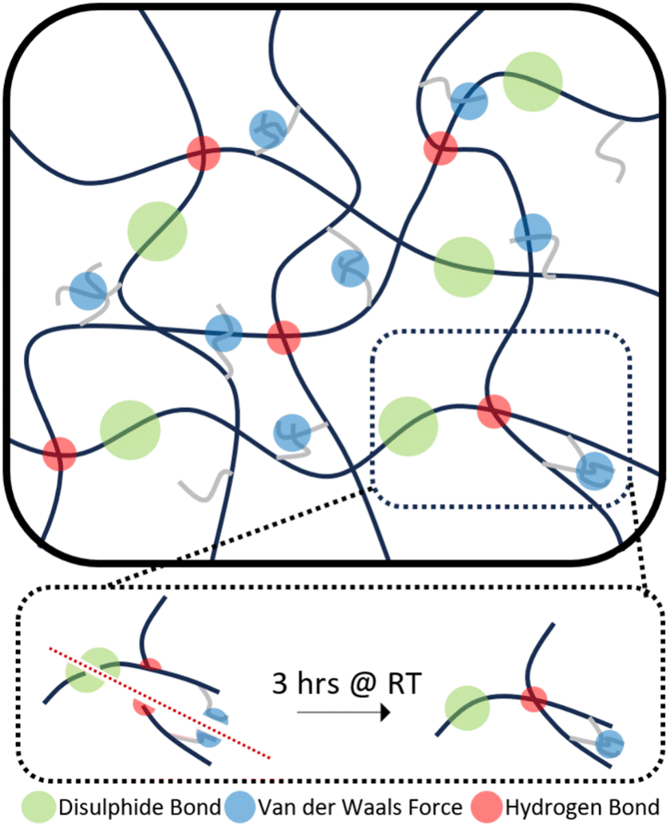 | ||
| Scheme 2 Synergistic self-healing mechanism of TPUs. | ||
From the above evaluations, it becomes apparent that P40 shows a good balance between an adequate concentration of self-healing disulphide bond while maintaining chains that are soft enough to allow the chain diffusion step to occur, facilitating the reparation process to occur fully. So, P40 was considered for further testing to understand the impact of the dynamic bond level on the self-healing efficiencies. The aliphatic disulphide bond containing the chain extender was replaced by HDO, as a way of removing the dynamic disulphide bond while keeping the chain length constant. The tensile curves for the HDO containing material (P40-H) can be seen in Fig. 7.
 | ||
| Fig. 7 Representative tensile stress–strain plots of P40-H. | ||
Fig. 7 shows a large difference in the curve shape in comparison to the disulphide-containing curve, namely the lack of a transition in the middle. As this transition was attributed to the self-healing of bonds, it can be deduced that P40-H either shows little self-healing or requires much longer times to heal as the same strain rate of 100 mm min−1 might be too fast for healing to occur. This hypothesis was confirmed through self-healing tests as the removal of the disulphide bond significantly decreased the self-healing efficiencies of both the UTS and elongation achieved. P40-H shows self-healing efficiencies of only 58% and 61% for elongation and UTS, respectively, after 3 hours of self-healing. This equates to a decrease in 33% efficiency for elongation and 47% for UTS through removal of the disulphide bond. Jian et al.15 determined that hydrogen bonding provided their polyurethanes with 46% self-healing of UTS, whereas with the presence of disulphide bonds, 100% was achieved. P40-H, produced herein, shows a 15% higher UTS self-healing efficiency in comparison, attributed to the dangling chains present in the diol. Some level of self-healing can still be achieved through hydrogen bonding and the van der Waals forces present in the dangling chains; however, the dynamic disulphide bond is required to reach high levels of self-healing in these TPUs.
Additionally, as self-healing utilises weaker sacrificial dynamic bonds with lower bonding energy than the polymer backbone, the removal of these bonds will result in a stronger material; this can be seen in the C–C bond, which is roughly 40% stronger than the S–S bond.55 This was further confirmed through P40-H, as each of the mechanical properties of the material showed significant improvement. Compared to P40, the UTS of P40-H is about four times higher at 1.69 ± 0.17 MPa, whilst still showing a respectable elongation to break of 1176 ± 3%. It also shows a higher Young's modulus at 1.40 ± 0.06 MPa. The stronger mechanical performance seen in P40-H suggests that it would be a good alternative to fossil fuel-based elastomers in applications where self-healing is less vital and where higher mechanical strength and elastic modulus are desired.
Hydrophobicity
Fig. 8 shows the water contact angles of P35, P40 and P45. Both P40 and P45 can be classified as hydrophobic, as they showed contact angles of 91.9 ± 0.43° and 94.8 ± 0.66°, respectively, whereas P35 is slightly more hydrophilic with a contact angle of 88.1 ± 0.72°. An increase in the hard segment increases the hydrophobicity of the material. The polarity of the surface impacts the hydrophobicity of the films; generally, by increasing polarity, hydrophobicity drops.56 Herein, the IPDI present within the hard segment plays a pivotal role in the hydrophobicity of the polymers.57 As the hard segment percentage is increased, the higher concentration of IPDI will result in lower polarity, and therefore higher hydrophobicity. This hydrophobic nature makes the polymers (P40 and P45) attractive materials for conductor applications through minimised risk of moisture related issues. The hydrophobicity is also an important factor in applications such as coatings,19 as well as for contact with skin, as the lower surface wettability suggests that sweat should not cause any swelling within the polymer.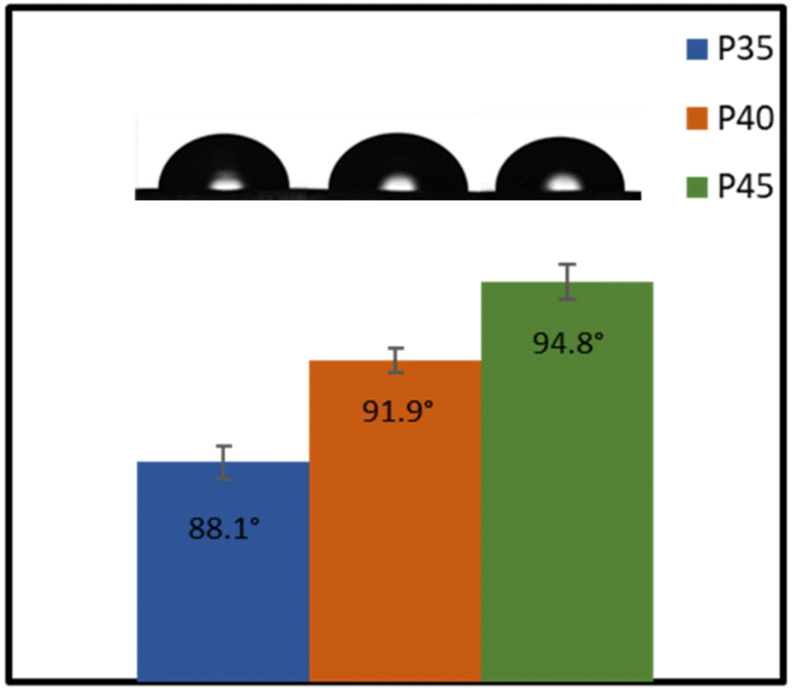 | ||
| Fig. 8 Water contact angles of TPUs. | ||
Applications
Wearable technology
The TPUs synthesised here show good promise in several different applications. One such example is for skin-based applications. In Fig. 9, a comparison between Young's modulus of synthesised TPUs and several different areas of skin is made. Each of the compositions shows Young's modulus comparable to that of a different area of skin, with P35 comparable with the postauricular mastoid, P40 showing similarity to the forearm and P45 being comparable to the forehead.58 This similarity in Young's modulus is vital to the viability of use in applications being exposed to the skin, as it lowers the risk of any delamination and discomfort during use.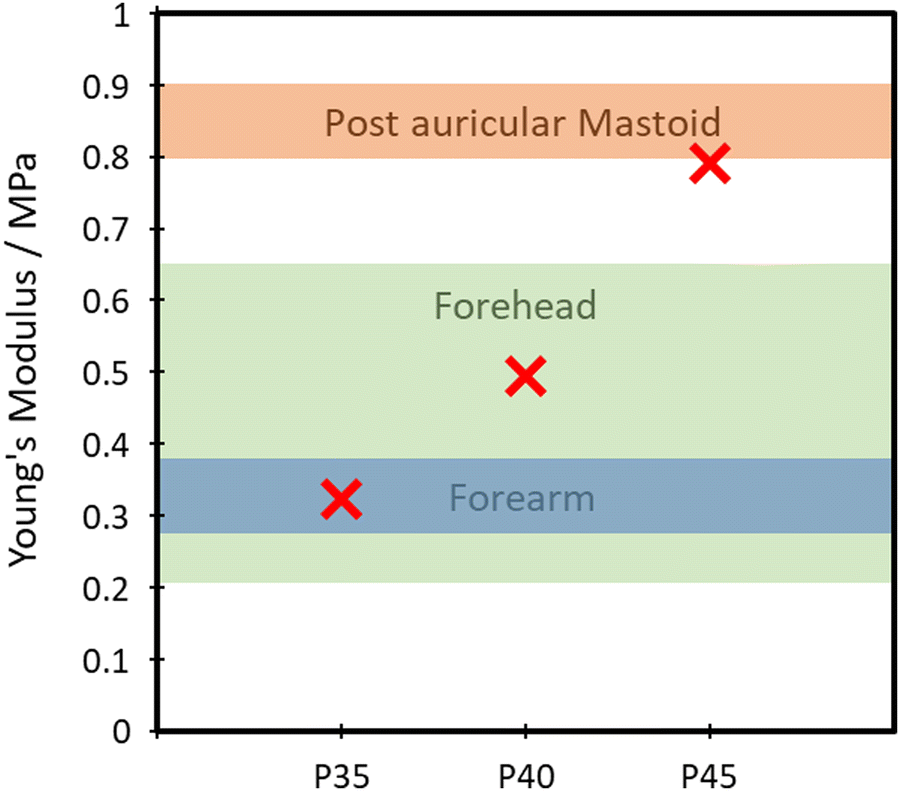 | ||
| Fig. 9 Comparison of the Young's modulus of skin and TPUs. | ||
The polymer's capability of potentially mimicking human skin shows potential for use in the field of wearable technologies. To test the polymer's ability to act as the matrix or substrate for conductive components, a Voltero V-One inkjet printer was utilised to print a circuit onto a P40 substrate using silver ink provided by the supplier. As shown in Fig. 10A, the silver ink was successfully printed onto the surface of the polymer, showing good adhesion between the ink and the polymer. Electrical conductivity versus strain tests were then performed on the circuit to confirm the polymer's suitability for stretchable conductor applications. The acquired relationship plot between relative resistance change and strain can be seen in Fig. 10B.
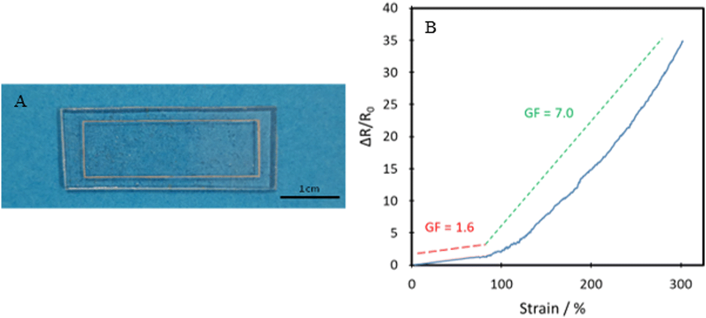 | ||
| Fig. 10 (A) Printed circuit based on silver ink and the P40 elastomer substrate for use in resistance testing, and (B) relative resistance change of printed circuit vs. strain (blue solid line). Red and green dashed lines show approximate gauge factors in two different strain ranges. | ||
Initially, a linear increase in resistance with strain is seen up to 80% as the circuit is stretched uniformly, and then a much steeper curved increase is seen up to 300% strain. The gauge factor (GF) found using eqn (2), which corresponds to the circuit's change in resistance proportional to the change in strain is examined.
 | (2) |
An electrical self-healing test was carried out on an alternative printed circuit (Fig. 11). The circuit and substrate were completely severed, followed by re-joining the two sides. Almost instantly, the diode was reilluminated, showing the effective electrical self-healing of the printed circuit. There was a small difference in brightness, which was qualitatively confirmed as the circuit before severing achieved an electrical conductivity of 2.3 × 10⁵ S m−1 whereas after re-connecting, around 2.1 × 10⁵ S m−1 was achieved. This lower value was due to reconnecting the pieces slightly off-centre, which could be improved by better alignment or printing thicker circuits.
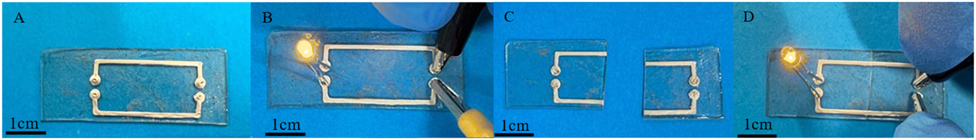 | ||
| Fig. 11 (A) Printed circuit based on silver ink and the P40 elastomer substrate, (B) circuit with illuminated diode, (C) damaged circuit, and (D) self-healed conductive pathway. | ||
The ability to mimic the properties of skin, the hydrophobicity, and the ability to provide a good substrate for use with electrically conductive materials confirm the potential of the new bio-based TPU for use in wearable technology and e-skins.
Smart textiles
The TPUs underwent further processing into fibres to test whether they could be transformed into fibrous forms for producing smart and stretchable textiles. Successful production of uniform fibres with little to no beading was achieved by pressurised gyration, as seen in Fig. 12A. The yarns of the produced fibres underwent mechanical testing, with the tensile stress vs. strain curve seen in Fig. 12B. | ||
| Fig. 12 (A) SEM image of spun P40 fibres, and (B) representative tensile stress–strain plot of spun P40 fibre yarns. | ||
The fibres have an average diameter of 3.31 ± 1.49 μm. This diameter could potentially be reduced by increasing the applied gas pressure during gyration but may come at a cost of reduced uniformity. The fibre topography showed a smooth surface, even with the use of chloroform as the solvent, which can often lead to the formation of surface nanopores.63 Although nanopores can increase the available surface area and be suitable for many biomedical applications, they could also cause a loss in UTS and lower tensile strength. It is seen that the fibres produced by this method show a high degree of alignment, which is especially useful in applications such as wearable devices and e-skin. Through spinning the polymer into fibres, the mechanical strength is significantly increased, reaching an average of 3.45 ± 0.24 MPa UTS. This can be explained by the fact that through the polymer solution being spun, the polymer chains are aligned and then locked in place upon evaporation of the solvent. Despite this, high elongation at break of the fibres is still seen, reaching 302 ± 22%, showing good improvement to some currently produced bio-based polyurethane fibres, typically reaching about 100–200%.64,65
Conclusions
Bio-based self-healing TPUs with varying hard segment molar percentages (35%, 40% and 45%) and triple self-healing mechanisms were successfully prepared using a bio-based diol (Pripol 2033), HEDS and IPDI, and their chemical structure was confirmed by FTIR and NMR. DSC results showed that the polymers were amorphous with Tg values of −6.6, −3.7 and −1.4 °C for P35, P40 and P45, respectively. High-level thermal stability was seen, with each composition showing a Tpeakd value above 360 °C.Each of the elastomers exhibited good mechanical properties, with the UTS increasing with the hard segment content, while elongation at break showed a significant decrease. P40 achieved a good combination of properties, with UTS and Young's modulus values of 0.37 ± 0.04 MPa and 0.49 ± 0.08 MPa, respectively, alongside an elongation to break of 1871 ± 161%. The TPU showed good resilience and shape recovery after cyclic loading to 100% strain. P40 also demonstrated medium-soft hardness with a Shore A value of 40.
P40 showed excellent self-healing at ambient temperature, being able to recover 69 ± 2% elongation and 101 ± 3% UTS after only 20 minutes at RT (≈20 °C), which increased to 91% for elongation and 108% for UTS within just 3 hours. This successful ambient rapid healing was achieved through a three-part synergistic self-healing approach of dynamic disulphide bonds alongside hydrogen bonds and van der Waals forces in the structure.
Water contact angles of over 90° and Young's moduli comparable to different areas of human skin demonstrate that these TPUs could suitably be used in wearable technology and e-skins. Another application as a substrate for conductive materials was seen through circuits printed onto the surface showing an electrical conductivity of 23.4 kS m−1, as well as a low gauge factor of 1.6 up to 80% strain. Additionally, the TPUs displayed high processibility through fibre spinning, showing uniformly sized non-beaded fibres, capable of reaching 302 ± 22% elongation, with a UTS of 3.45 ± 0.24 MPa.
The work presented herein demonstrates that these novel bio-based, self-healing TPUs have potential in stretchable conductors, wearable technologies, e-skins, smart textiles, etc. The one-pot synthesis allows for the production of these TPUs to be readily scaled up. While exceptional ambient temperature self-healing is achieved, further research can be carried out into improving mechanical strength and resilience to broaden the applications of this type of bio-based self-healing elastomer.
Author contributions
B. C. conceived and supervised the project, B. C. and T. G. designed the experiments, T. G. performed the experiments and analysed data, J. A. and H. M. performed fibre spinning experiments, M. E. supervised the spinning work, T. G. wrote the first draft of the manuscript and edited the manuscript. B. C., H. M. and M. E. reviewed and edited the manuscript.Data availability
The dataset underpinning this article is available on PURE for open access, with a description of this article title and DOI.Conflicts of interest
There are no conflicts to declare.Acknowledgements
The QUB authors thank the Engineering and Physical Research Council (EPSRC) for financial support of this work under EP/R5131118/1 – 2278068 and EP/W018977/1. The UCL authors are grateful to the EPSRC for funding pressurised gyration research (EP/S016872/1, EP/N034228/1, and EP/L023059/1).References
- S. Dutta and N. Karak, Prog. Org. Coat., 2005, 53, 147–152 CrossRef CAS.
- X. Zhou, T. Zhang, D. Guo and N. Gu, Colloids Surf., 2014, 441, 34–42 CrossRef CAS.
- R. Deng, P. Davies and A. K. Bajaj, J. Sound Vib., 2003, 262, 391–417 CrossRef.
- W. B. Ying, G. Wang, Z. Kong, C. K. Yao, Y. Wang, H. Hu, F. Li, C. Chen, Y. Tian, J. Zhang, R. Zhang and J. Zhu, Adv. Funct. Mater., 2021, 31, 2009869 CrossRef CAS.
- C. Xu and F. Ferdosian, Conversion of Lignin into Bio-Based Chemicals and Materials, Springer, Berlin, Heidelberg, 1st edn, 2017 Search PubMed.
- W. Ou, H. Qiu, Z. Chen and K. Xu, Biomater., 2011, 32, 3178–3188 CrossRef CAS PubMed.
- F. V. Souza and D. H. Allen, Int. J. Solids Struct., 2011, 48, 3160–3175 CrossRef.
- Y. Han, X. Wu, X. Zhang and C. Lu, ACS Appl. Mater. Interfaces, 2017, 9, 20106–20114 CrossRef CAS PubMed.
- A. Tariq, Z. U. Arif, M. Y. Khalid, M. Hossain, P. I. Rasool, R. Umer and S. Ramakrishna, Adv. Eng. Mater., 2023, 25, 2301074 CrossRef CAS.
- S. R. White, N. R. Sottos, P. H. Geubelle, J. S. Moore, M. R. Kessler, S. R. Sriram, E. N. Brown and S. Viswanathan, Nature, 2001, 409, 794–797 CrossRef CAS PubMed.
- C. Gong, J. Liang, W. Hu, X. Niu, S. Ma, H. T. Hahn and Q. Pei, Adv. Mater., 2013, 25, 4186–4191 CrossRef CAS PubMed.
- D. Mozhdehi, S. Ayala, O. R. Cromwell and Z. Guan, J. Am. Chem. Soc., 2014, 136, 16128–16131 CrossRef CAS PubMed.
- T. Wu, E. Gray and B. Chen, J. Mater. Chem. C, 2018, 6, 6200–6207 RSC.
- X. Wu, J. Li, G. Li, L. Ling, G. Zhang, R. Sun and C.-P. Wong, J. Appl. Polym. Sci., 2018, 135, 46532 CrossRef.
- X. Jian, Y. Hu, W. Zhou and L. Xiao, Polym. Adv. Technol., 2018, 29, 463–469 CrossRef CAS.
- G. Ye and T. Jiang, Polymers, 2021, 13, 2936 CrossRef CAS PubMed.
- W. M. Xu, M. Z. Rong and M. Q. Zhang, J. Mater. Chem. A, 2016, 4, 10683–10690 RSC.
- T. Wu and B. Chen, RSC Adv., 2017, 7, 20422–20429 RSC.
- Y. Nurhamiyah, A. Amir, M. Finnegan, E. Themistou, M. Edirisinghe and B. Chen, ACS Appl. Mater. Interfaces, 2021, 13, 6720–6730 CrossRef CAS PubMed.
- S. Mahalingam, S. Homer-Vanniasinkam and M. Edirisinghe, Mater. Des., 2019, 178, 107846 CrossRef CAS.
- J. Pagacz, K. N. Raftopoulos, A. Leszczyńska and K. Pielichowski, J. Therm. Anal. Calorim., 2016, 123, 1225–1237 CrossRef CAS.
- M. Sultan, K. M. Zia, H. N. Bhatti, T. Jamil, R. Hussain and M. Zuber, Carbohydr. Polym., 2012, 87, 397–404 CrossRef CAS PubMed.
- H. G. M. Edwards, D. W. Farwell and A. C. Williams, Spectrochim. Acta, Part A, 1994, 50, 807–811 CrossRef.
- A. Abbasi, G. Mir Mohamad Sadeghi and I. Ghasemi, Polym. Sci., Ser. B, 2017, 59, 526–536 CrossRef CAS.
- Z. Chen, N. Hadjichristidis, X. Feng and Y. Gnanou, Macromolecules, 2017, 50, 2320–2328 CrossRef CAS.
- M. Pegoraro, A. Galbiati and G. Ricca, J. Appl. Polym. Sci., 2003, 87, 347–357 CrossRef CAS.
- D.-I. Lim, H.-S. Park, J.-H. Park, J. C. Knowles and M.-S. Gong, J. Bioact. Compat., 2013, 28, 274–288 CrossRef CAS PubMed.
- K. Kuwajima and R. L. Baldwin, J. Mol. Biol., 1983, 169, 299–323 CrossRef CAS PubMed.
- C. Delides, R. A. Pethrick, A. V. Cunliffe and P. G. Klein, Polymer, 1981, 22, 1205–1210 CrossRef CAS.
- N. Kasmi, C. Pinel, D. Da Silva Perez, R. Dieden and Y. Habibi, Polym. Chem., 2021, 12, 991–1001 RSC.
- Y. M. Lee, J. C. Lee and B. K. Kim, Polymer, 1994, 35, 1095–1099 CrossRef CAS.
- S.-M. Kim, H. Jeon, S.-H. Shin, S.-A. Park, J. Jegal, S. Y. Hwang, D. X. Oh and J. Park, Adv. Mater., 2018, 30, 1705145 CrossRef PubMed.
- G. Leone, B. Palucci, G. Zanchin, A. Vignali, G. Ricci and F. Bertini, ACS Appl. Polym. Mater., 2022, 4, 3770–3778 CrossRef CAS.
- J. He, F. Song, X. Li, L. Chen, X. Gong and W. Tu, J. Polym. Res., 2021, 28, 122 CrossRef CAS.
- M. F. Sonnenschein, Polyurethanes: science, technology, markets, and trends, Wiley, Hoboken, New Jersey, 2015 Search PubMed.
- N. Ketata, C. Sanglar, H. Waton, S. Alamercery, F. Delolme, G. Raffin and M. F. Grenier-Loustalot, Polym. Polym. Compos., 2005, 13, 1–26 CAS.
- F. S. Chuang, Polym. Degrad. Stab., 2007, 92, 1393–1407 CrossRef CAS.
- W. Zhang, X. Li and R. Yang, Polym. Degrad. Stab., 2011, 96, 1821–1832 CrossRef CAS.
- H. Bakhshi, H. Yeganeh, A. Yari and S. K. Nezhad, J. Mater. Sci., 2014, 49, 5365–5377 CrossRef CAS.
- K. Tachibana and H. Abe, Polym. Degrad. Stab., 2019, 167, 283–291 CrossRef CAS.
- G. Zhang, J. Pei, R. Li, P. Li and B. Zhou, Mater. Res. Express, 2018, 5, 105301 CrossRef.
- S. Mondal and J. L. Hu, Polym. Plas. Technol., 2007, 46, 37–41 CrossRef CAS.
- V. T. Tran, Md. T. I. Mredha, J. Y. Na, J.-K. Seon, J. Cui and I. Jeon, Chem. Eng. J., 2020, 394, 124941 CrossRef CAS.
- Rahco Rubber, IIR Elastomer Technical Datasheet. [Accessed on 7th July 2023]. Available Online: https://rahco-rubber.com/materials/iir-butyl-rubber/, 2023.
- S. Mihara and S. Takeoka, Polym. Adv. Technol., 2022, 33, 1180–1189 CrossRef CAS.
- Smooth-On, Inc. Dragon Skin 30 Elastomer Technical Datasheet. [Accessed 7th July 2023]. Available Online: https://www.smooth-on.com/products/dragon-skin-30/, Dragon Skin 30 Product Information., https://www.smooth-on.com/products/dragon-skin-30/.
- N. Candau, G. Stoclet, J.-F. Tahon, A. Demongeot, E. Yilgor, I. Yilgor, Y. Z. Menceloglu and O. Oguz, Polymer, 2021, 223, 123708 CrossRef CAS.
- K. Cui, T. L. Sun, X. Liang, K. Nakajima, Y. N. Ye, L. Chen, T. Kurokawa and J. P. Gong, Phys. Rev. Lett., 2018, 121, 185501 CrossRef PubMed.
- L. Bartolomé, J. Aurrekoetxea, M. A. Urchegui and W. Tato, Mater. Des., 2013, 49, 974–980 CrossRef.
- X. Zhou, L. Wang, X. Cao, Q. Yin and G. Weng, J. Appl. Polym. Sci., 2019, 136, 47278 CrossRef.
- C. S. Paik Sung, C. B. Hu and C. S. Wu, Macromolecules, 1980, 13, 111–116 CrossRef.
- C. D. Eisenbach and W. Gronski, Makromol. Chem., Rapid Commun., 1983, 4, 707–713 CrossRef CAS.
- M. Yamaguchi, S. Ono and M. Terano, Mater. Lett., 2007, 61, 1396–1399 CrossRef CAS.
- S. Utrera-Barrios, R. Verdejo, M. A. López-Manchado and M. Hernández Santana, Mater. Horiz., 2020, 7, 2882–2902 RSC.
- R. J. W. Cremlyn, An introduction to organosulfur chemistry, Wiley, Chichester, New York, 1996 Search PubMed.
- N. Giovambattista, P. G. Debenedetti and P. J. Rossky, J. Phys. Chem. B, 2007, 111, 9581–9587 CrossRef CAS PubMed.
- P. Król and B. Król, Colloid Polym. Sci., 2012, 290, 879–893 CrossRef PubMed.
- M. F. Griffin, B. C. Leung, Y. Premakumar, M. Szarko and P. E. Butler, J. Otolaryngol - Head & Neck Surg., 2017, 46, 33 Search PubMed.
- P. Bajpai, Biermann's Handbook of Pulp and Paper, Elsevier, 2018, pp. 483–492 Search PubMed.
- S. Yao and Y. Zhu, Nanoscale, 2014, 6, 2345 RSC.
- J. Lee, S. Kim, J. Lee, D. Yang, B. C. Park, S. Ryu and I. Park, Nanoscale, 2014, 6, 11932–11939 RSC.
- J. H. Cho, S.-H. Ha and J.-M. Kim, Nanotechnology, 2018, 29, 155501 CrossRef PubMed.
- U. Illangakoon, S. Mahalingam, R. Matharu and M. Edirisinghe, Polymers, 2017, 9, 508 CrossRef PubMed.
- P. P. Tsai, W. Chen and J. R. Roth, Int. Nonwovens J., 2004, os-13, 17 Search PubMed.
- E. Łyszczarz, W. Brniak, J. Szafraniec-Szczęsny, T. M. Majka, D. Majda, M. Zych, K. Pielichowski and R. Jachowicz, Pharmaceutics, 2021, 13, 1122 CrossRef PubMed.
Footnote |
| † Electronic supplementary information (ESI) available. See DOI: https://doi.org/10.1039/d4ma00289j |
| This journal is © The Royal Society of Chemistry 2024 |