
 Open Access Article
 This Open Access Article is licensed under a Creative Commons Attribution-Non Commercial 3.0 Unported Licence
Structurally realistic carbide-derived carbon model in annealing molecular dynamics methodology with analytic bond-order potential
Koushik
Sarkar
and
Muhammad Anisuzzaman
Talukder
 *
*
Department of Electrical and Electronic Engineering, Bangladesh University of Engineering and Technology, Dhaka, 1205, Bangladesh. E-mail: koushik1564@gmail.com; anis@eee.buet.ac.bd
First published on 7th June 2024
Abstract
A realistic carbide-derived carbon (CDC) model is developed with the analytic bond-order potential (ABOP) using annealing molecular dynamics methodology. ABOP, predominantly used to study crystalline carbon structures, has been applied to produce structurally accurate amorphous carbon structures. The features of the simulated structures have been compared with those experimentally determined from chemically synthesized amorphous CDC materials. Notably, the structural changes observed by varying simulation temperatures closely agree with the trend observed in experiments with the variation of chlorination temperature. The Arrhenius model establishes the similitude between the simulated amorphous carbon structures and their experimental reports, relating the simulation annealing temperature with the experimental chlorination temperature. The atomistic model of porous carbon structures will facilitate their investigation and optimization in the application of gas storage and energy storage devices.
1 Introduction
Carbide-derived carbon (CDC) is a class of nanoporous carbon structures featuring materials from amorphous carbon structures to highly ordered structures such as carbon nanotubes and graphene.1 CDC structures derived from the selective removal of metals from carbide materials have applications in different fields due to their high surface area and well-defined tunable pore size distribution (PSD).2–4 Generally, the synthesis process involves a reaction between the precursor material and chlorine gas to etch out metal selectively, followed by thermal annealing. The properties of the CDC structure, including PSD, are significantly influenced by the choice of the precursor material and the chemical reaction temperature, also known as chlorination temperature.2 Various binary and ternary materials, such as SiC,5 TiC,6 TiAlC2,7 and ZrC,8 have been used as the precursor material for CDC synthesis. The most prominent fields of application for porous carbon structures include electrochemical energy storage devices,6,9–12 protein absorption,13 and gas adsorption and storage.14,15 Structures synthesized at high temperatures have a large percentage of sp2-hybridized atoms, resulting in high conductivity.16 In addition, the pore diameter in the electrode and the electrolyte ions' size significantly influence the specific capacitance and charging and discharging mechanisms in electrochemical capacitors.17,18 Electrochemical capacitors with exceptionally high capacitance have been developed by tuning the PSD to match the size of electrolyte ions with the pore diameter.9CDC structures have been extensively characterized with neutron diffraction, X-ray diffraction, and electron microscopy, and structural patterns and trends with synthesis conditions have been observed.19,20 However, empirical methods need more resolution to fully characterize highly amorphous and heterogeneous nanostructures, limiting the knowledge about the structural features that influence performance in different applications.21 Nanoporous carbon structures have been widely modeled as the slit-pore model in simulation works.22 This model consists of two parallel graphene sheets separated by a characterizing width commonly defined by the peak pore width from experimental PSD. Other geometric models based on fullerene23 and polymeric fragments24 have been developed to emulate realistic porous carbon structures better. In such models, heterogeneity of realistic carbon models, such as the effects of surface curvature, edge, and PSD, cannot be incorporated. However, the effects of ion or gas molecule transport through interconnected porous structures are of significant importance in electrochemical capacitors and gas storage applications.25,26 Therefore, a realistic and accurate porous carbon model is necessary to gain insight into the effects of structural heterogeneity on the performance of gas adsorption, electrochemical capacitance, and ion dynamics.
A more robust approach to modeling nanoporous carbon structure is through atomistic simulations. One such approach is the reconstructive method, where the CDC structure is formed in the reverse Monte Carlo (RMC)27 simulation technique by generating an atomic configuration conforming to an experimentally synthesized CDC sample parameter. The RMC algorithm can be used with a forcefield, known as the hybrid RMC (HRMC), to avoid unphysical structural features.28 This reconstructive approach has been implemented to develop the atomistic model of CDC and other nanoporous carbon structures.29–32 The most critical shortcoming of this approach is the dependency on experimental data, which are subject to various systematic biases. Secondly, the radial distribution function (RDF) data used in the reconstruction cannot capture the nanometer-sized features, such as porosity and surface curvature. Thirdly, several structures with different features can be generated from one-dimensional RDF due to a lack of uniqueness.33 In addition, the RMC approach only reconstructs an atomistic model of experimentally characterized nanoporous carbon material but cannot predict carbon structures developed in different synthesis conditions.
An alternative strategy of atomistic simulation is the mimetic approach, which does not require any experimental data and can predict features of carbon structures developed in various conditions. Among the mimetic approaches, the quench molecular dynamics (QMD) method has been studied and applied extensively to model amorphous silica,34–36 metal,37 and carbon structures.38 Previous QMD studies have attempted to model porous carbon structures with different force fields, such as the Tersoff potential,39 reactive summation state (RSS),38 and the ReaxFF potential.40 One shortcoming of the previous QMD studies was the absence of graphene layer stacking in simulated structures, attributed to the short-range nature of the RSS potential, as this potential cannot model long-range attraction between graphene layers.21 In a subsequent study, the CDC structure was modeled with the ReaxFF potential, which includes long-range Van-der-Waals and electrostatic interactions to model the non-bonded interaction between atoms.41 Despite incorporating a reactive force field with long-range interaction, only a small amount of graphene sheet stacking was observed at the slowest quench rate of 1 K per picosecond.
The mimetic approach also includes the annealing methodology instead of quenching for generating CDC. The annealing temperature can be correlated with the reaction temperature of CDC synthesis, leading to a better match between the simulation and experimental procedures. The atomistic model of amorphous carbon has been developed with different force fields, but graphene layer stacking present in experimentally obtained CDC samples was not observed.21,42,43 Recently, de Tomas et al. carried out annealing on a metal-removed carbide lattice with the environment-dependent interatomic potential (EDIP)44 force field and observed good agreement with experimental results.45 Graphene sheet stacking was observed in simulated structures at high temperatures, conforming to experimentally observed TEM images.
The forcefield used in molecular dynamics (MD) simulations critically determines the accuracy of the simulated CDC model and its agreement with experimental data. Several forcefields for generating CDC models have been reported in the literature. However, not all potential functions can produce carbon structures with realistic features of CDC materials.45,46 Analytic bond-order potential (ABOP) has been derived from the tight binding model for σ and π bond order through quantum mechanical analysis.47 This potential function has been recently re-parameterized for carbon materials to model the crystalline growth of carbon materials.48 ABOP has been re-parameterized for modeling the crystalline growth of graphene, graphite, and carbon nanotubes. Although this forcefield has been incorporated in simulating crystalline structures, such as penta-graphene,49 antimony-carbide,50 and graphene composite,51 its application in simulating amorphous carbon has not been investigated except for the recent study by de Tomas et al.46 It was reported that annealing with ABOP generates hexagonal ring-dominated highly graphitized carbon structures. The hexagonal ring percentage formed with ABOP is only second to that formed with EDIP and equal to that formed with the Gaussian approximation potential (GAP)52 among all the potentials studied. Although a machine learning-based potential, such as GAP, is expected to produce a CDC atomistic model with better conformity to the experimental sample, the exceptionally high computational cost, almost 100 times more than ABOP, makes studying large systems with tens of thousands of atoms difficult.
A forcefield capable of producing structures with a high percentage of hexagonal rings is essential for generating a realistic CDC model, as these materials are graphitic. Forcefields, such as AIREBO, Tersoff, extended Tersoff, Tersoff-S, and Erhart/Albe, have comparable or lower computational costs than ABOP.46 However, these forcefields offer much fewer hexagonal rings and more higher-order rings per atom than ABOP.46 Consequently, ABOP is the best potential with a moderate computational cost suitable for generating highly graphitized amorphous structure. In addition, the fact that ABOP was developed to model the crystalline growth of carbon material and the experimental CDC samples are highly graphitic calls for an in-depth investigation of this forcefield in synthesizing a realistic CDC model.
Only recently, Wang et al. demonstrated graphitized nanoporous carbon structures with GAP after retraining the model and introducing several algorithmic modifications to speed up the simulation.53 Wang et al. also reported that the newly trained potential is almost seven times faster than the original GAP. Their work produced nanoporous carbon structures with different densities and compared the simulated diffraction patterns, partial distribution functions, and pair distribution functions with the experimental data.53 Further investigation is necessary to compare the simulated coordination number, adsorption isotherm, and average pore size with experimental data extracted from samples synthesized at different temperatures to determine to what extent the simulated structures generated with this potential conform to experimental samples.
This work explores the application of ABOP in simulating an amorphous carbon model and demonstrates that a structurally realistic CDC model can be generated in annealing molecular dynamics methodology with this potential. Due to the low computational cost associated with the ABOP potential, a large carbon model with tens of thousands of atoms and simulation time on the order of nanoseconds can be simulated with moderate computational capacity. In this work, the simulated carbon models are studied extensively, and structural features, such as the coordination fraction, ring size distribution (RSD), RDF, and PSD, have been investigated for the structures generated with different annealing temperatures. These simulated features are compared with experimental data of titanium CDC samples. It is observed that the simulated structures show the same trend as the experimental samples with the variation of chlorination temperature. The concept of temperature acceleration modeled by the Arrhenius equation is applied to develop a relation between the simulation's annealing temperature and the experiment's chlorination temperature. Close agreements are observed between features of the experimental sample and features of the simulated structure and in the trend associated with temperature variation. Correlation between experimental and simulation temperatures and agreement of the simulated structures with the experimental ones imply that our methodology can produce an atomistic model of experimentally synthesized CDC structure at any intermediate temperature.
2 Simulation methodology
In this work, molecular dynamics simulation has been carried out with ABOP forcefield in LAMMPS54 software package. The procedure follows an annealing methodology, where the simulation temperature is kept constant for a long time to generate the amorphous carbon structure. This methodology strongly resembles the experimental synthesis of porous carbon formation, where the chemical reaction is carried out at a constant temperature. In subsequent discussions, annealing temperatures represent temperatures set in the simulations.In this work, the initial structure is generated by placing carbon atoms at the lattice sites of a simple cubic (SC) structure and then introducing slight random variations in their positions. The mesopore regime comprises pores with diameters from 2 to 50 nm. The simulation box size needs to be several times larger than the size of the largest pores to capture the formation of pores with more than 2 nm diameter in simulation. This work set the simulation box size to ∼10 nm for all simulation temperatures. As observed during simulation, some atoms form C2 carbon pairs and remain detached from the solid structure. The percentage of such detached atoms increases as the annealing temperature increases. The mass density is calculated by dividing the total mass of bonded atoms in the simulation box by the volume of the simulation box. To keep the final mass density of the annealed structure close to the experimentally observed bulk mass density of 0.95 g per cc, the initial simulation box length is varied slightly while keeping the atom number constant to increase the initial density for increased annealing temperatures. The total number of atoms is kept constant at 54![[thin space (1/6-em)]](https://www.rsc.org/images/entities/char_2009.gif) 872, while the simulation box length is varied with temperature as given in Table 1. Several trial simulations are carried out with different initial densities for simulation temperatures above 1500 K to determine the initial length of the cubic simulation box.
872, while the simulation box length is varied with temperature as given in Table 1. Several trial simulations are carried out with different initial densities for simulation temperatures above 1500 K to determine the initial length of the cubic simulation box.
| Annealing temperature, TS (K) | Initial density (g cm−3) | Final density (g cm−3) | Simulation box length, L (nm) | Simulation time (ns) |
|---|---|---|---|---|
| 1000 | 0.95 | 0.95 | 10.48 | 0.2 |
| 1500 | 0.95 | 0.95 | 10.48 | 0.2 |
| 2000 | 0.96 | 0.947 | 10.446 | 0.5 |
| 2500 | 0.97 | 0.95 | 10.41 | 5 |
| 3000 | 1.03 | 0.946 | 10.2 | 10 |
The carbon structure is annealed at 1000, 1500, 2000, 2500, and 3000 K with three-dimensional periodic boundary conditions. The simulation temperature (TS) is significantly greater than the experimental temperatures (Te) to capture the reaction dynamics within reasonable simulation time by molecular dynamics simulation. The initial velocity of carbon atoms is assigned by sampling a Maxwell–Boltzmann distribution at the annealing temperature. The simulation is carried out long enough for each temperature until the percentage of sp2 bonded atoms is saturated. Fig. 1 shows the time-evolution of sp2 bonded atom fraction. The time is normalized by the total simulation duration for different temperatures as given in Table 1. It is observed from Fig. 1 that longer simulation time is required for higher temperatures to produce a structure where the sp2 bonded atom percentage has saturated. The fractions of carbon atoms with other coordination numbers follow a similar trend, although the saturated values vary for different temperatures. The percentage of sp2 bonded carbon atoms increases sharply at the beginning of the simulation and gradually reaches a steady state value, showing an increasing trend with increasing simulation temperature. Once the bonded atom percentage saturates, the structure shows no significant evolution with time. The simulation duration varies from 200 ps to 10 ns for TS = 1500 to 3000 K, as given in Table 1. The temperature control is imposed by canonical sampling thermostat with Hamiltonian dynamics developed by Bussi et al.55 The relaxation constant for the Bussi thermostat has been set to 10 fs. This simulation applies the Velocity-Verlet integration algorithm with a time-step of 0.5 fs. The time-step is set to a relatively high value as the structures only contain carbon atoms.41
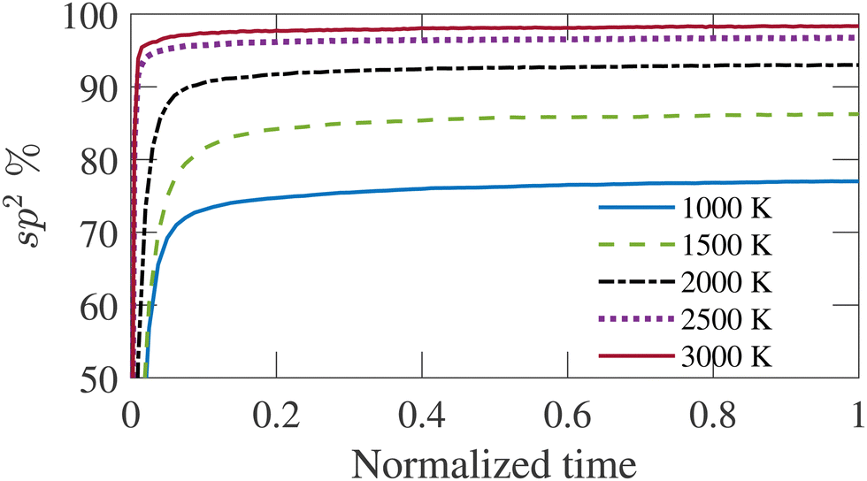 | ||
| Fig. 1 Variation of sp2 bonded atom percentage with time for simulation temperatures (TS). The time is normalized by the total duration of the simulation. | ||
The high temperatures of the annealing simulation render the atoms significantly deviated from their mean position in the structures produced from the simulation. As a result, the energy of the structure obtained from the annealing simulation is minimized in the conjugate gradient algorithm before further analysis. The non-bonded atom pairs are removed by evaluating the coordination number of each atom and discarding any atom with a coordination number less than 2. The coordination number is calculated by counting the neighbors within a cutoff of 1.85 Å. This cutoff also defines bonding between atoms. Snapshots of cross-sectional views of annealed structures are rendered, and RDFs are calculated with the OVITO software package.56 RSD is calculated using the algorithm developed by Franzblau et al. to determine the shortest path ring.57 Pair distribution functions (PDF) are calculated using eqn (1)
| G(r) = 4πrρ0[g(r) − 1], | (1) |
For comparison with experimental results, RDF data have been convoluted with a Gaussian distribution having a standard deviation of 0.11 Å to consider the effect of finite maximum scattering vector.45 PSDs are derived using the code written by Bhattacharya et al.36,58 This algorithm calculates the pore diameter by evaluating the diameter of spheres that do not overlap with each other and the pore walls. The minimum probe diameter has been set to 3.4 Å with an error tolerance of 0.01 to terminate the iterative process. The PSD calculated in this way is referred to as the geometric PSD in literature.
The adsorptive property of the MD-generated carbon model structures has been studied by simulating adsorption isotherm with grand canonical Monte Carlo (GCMC) simulation in Cassandra open source software package.59 The simulations consider argon as the adsorbate fluid at a constant temperature of 77 K. Interaction between the carbon and argon atoms is modeled with 12-6 Lennard-Jones (LJ) potential with a cutoff distance of 15 Å. For carbon and argon, the energy parameters are εC/kB = 28.0 K, εAr/kB = 120.0 K, respectively, and the size parameters are σC = 3.4 Å, σAr = 3.405 Å, respectively.60 The cross parameters for interaction between argon and carbon are calculated from the Lorentz–Bertholet mixing rule.61 The number and position of only argon atoms have been varied in GCMC simulation to achieve the lowest energy state, while the carbon atoms are considered to be fixed in position and number. Equal probabilities are set for the insertion, deletion, and translation of atoms in this simulation. Multiple short simulations of 2 million steps have been carried out at each pressure point till the number of argon atoms saturates for a particular pressure. The number of atoms saturates within 4 million steps at most of the pressure points.
Establishing a relationship between experimentally produced CDC structures and simulated porous carbon structures is of major concern in the field of molecular dynamics simulation. In recent work, the concept of temperature acceleration62 has been applied to develop a relationship between annealing temperature of simulation and experimental temperature, assuming the reaction dynamics can be modeled by Arrhenius behaviour, as given by45
 | (2) |
 is the calculated simulation temperature, kB is the Boltzmann constant, te is the experimental synthesis time set to 104 s from experimental work of Dash et al.,6 and ts is the simulation time, as given in Table 1. The only unknown parameter in eqn (2) is the activation energy parameter Ea, which was estimated by comparing the PDF, sp2 percentage, and cross-sectional snapshots of simulated structures to reported data of experimentally synthesized CDC structures. Primarily, the correlation between TS and Te was aimed to establish in a way such that the trend observed in experimental data with temperature agrees with the simulated data. In the process, good agreement between experimental and simulated parameters for individual temperatures was observed, especially for PDFs, as shown in Fig. 6.
Establishing the one-to-one correspondence between Te and TS starts by calculating  from eqn (2) considering Te as an input. Then, the closest simulation temperature (TS) to the calculated temperature
  is regarded to correspond to the experimental temperature (Te). The maximum deviation between TS and
  is calculated to be 8.6% when Te = 1200 °C, denoting the upper limit of temperature that can be evaluated by this simple model. The range of value for Te covered by this model, and the variation of
  as well as TS are depicted in Fig. 2. Fig. 2 shows the variation of
  with Te and the corresponding simulation temperatures (TS). Estimation of Ea enabled the calculation of TS from any Te provided that 400° < Te < 1200 °C. Once TS is known, our methodology can generate the atomistic model of the CDC structure experimentally synthesized at Te temperature.
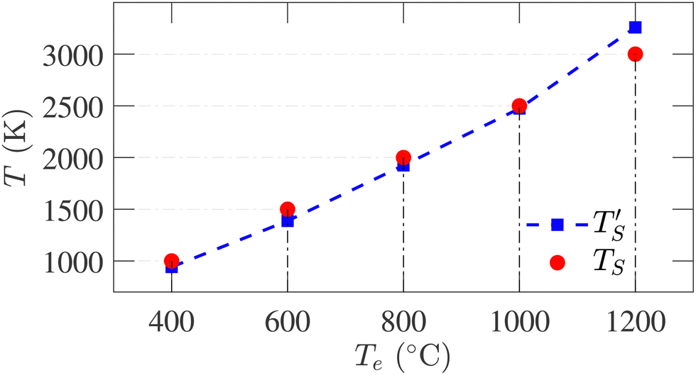 | ||
| Fig. 2 Correlation between simulation temperature (TS) and experimental temperature (Te) calculated from eqn (1). The experimental temperatures and time (te = 104 s) are taken from ref. 6. The simulation parameters are tabulated in Table 1. | ||
3 Results
In this work, annealing molecular dynamics simulations have been conducted at five temperatures ranging from 1000 to 3000 K. The simulation parameters are summarized in Table 1. As previously observed, isolated atom percentages increase as the annealing temperature increases in simulations. Table 1 shows the initial densities of carbon structures in the simulation box for different temperatures that result in the desired final mass density of 0.95 g per cc. The maximum deviation observed is only 0.42%, which occurs at 3000 K.Fig. 3 compares the cross-sectional snapshots of simulated annealed structures at different temperatures with TEM images of samples at corresponding experimental temperatures.10,19 The simulated snapshots and experimental TEM images are compared side by side to elucidate the similar trends in graphitic sheets and pore sizes in experimental and simulated structures with increasing temperatures. Snapshots of a thin cross-section of the simulated structures are shown to visualize pores better. Although void pores cannot be directly observed in the experimental samples, their sizes and distributions can be estimated by looking at the surrounding graphitic pore walls. Highly amorphous carbon structures with no visible graphene sheet fragments are formed for Te ≤ 600 °C. Relatively small-sized pores are observed to be uniformly distributed throughout the structure. For Te > 800 °C, structures with larger and planar graphene sheets and larger pore sizes emerge. With increasing temperature, the structures manifest larger straight graphene fragments stacked together. The CDC structure synthesized at Te = 1200 °C exhibits the highest number of stacked graphene layers, as shown in Fig. 3(e).
 | ||
| Fig. 3 (a)–(e) TEM images of experimental samples synthesized at temperatures (Te) of 400, 600, 800, 1000, and 1200 °C, respectively. (f)–(j) Cross-sectional view of 1.5 nm slab of simulated structure annealed at TS = 1000, 1500, 2000, 2500, and 3000 K, respectively. TEM images in panels (a), (d), and (e) are reprinted with permission from ref. 19. Copyright 2015 American Chemical Society. TEM images in panels (b) and (c) are reprinted with permission from ref. 10. Copyright 2006 Elsevier Ltd. | ||
At TS < 2000 K, carbon structures with small curved graphene fragments with tiny diameter pores less than 20 Å are formed. The pores are observed to be distributed uniformly throughout the structures. At TS = 2000 K, large graphene sheets are observed, agreeing with the TEM image of the structure at Te = 800 °C, although the graphene layer stacking is not observed in this simulated structure. Large graphene sheets with small curvature and double-layer stacking are observed in the simulated structure annealed at 2500 K. Graphene sheet stacking observed at this temperature is in excellent agreement with the experimental TEM image. When TS = 3000 K, a high degree of long-range order with flat graphene sheet stacking up to 3 layers is observed. Even though a high level of graphene sheet stacking up to four layers, as observed in experimental samples, could not be generated with simulation. However, the trend present in experiments has been clearly captured by the simulated structures with the variation of the simulation temperature.
RSD is a measure of the medium-range order of an amorphous structure. A ring is defined as a closed path that can be traced among bonded atoms. The ring size is determined by counting the number of atoms or bonds in the closed path. The RSD of graphene consists of only hexagonal rings with a ring per atom value of 0.5, the highest percentage of a structure's hexagonal ring fraction. The simulated structures are analyzed, and the number of triangular to octagonal rings is counted. For comparing the RSD of different annealed structures, the ring counts are divided by the total number of atoms remaining in the simulation box after removing the isolated atoms. The RSD of physical samples cannot be determined by experimental characterization tools. Therefore, simulation results for this parameter are not compared with experimental data. It has been observed that no triangular and quadrilateral rings are formed in annealed structures at any simulation temperature. The summation of pentagonal to octagonal rings per atom increases initially and saturates at 2000 K as the hexagonal ring fraction approaches the graphitic limit. For all temperatures, the RSD is dominated by the hexagonal ring, and this percentage increases with the increasing simulation temperature, as shown in Fig. 4(a). It implies that the annealed structures become increasingly graphitic, resulting in a higher degree of short-range order. The percentage of other rings, except for hexagonal rings, decreases with the increasing temperature.
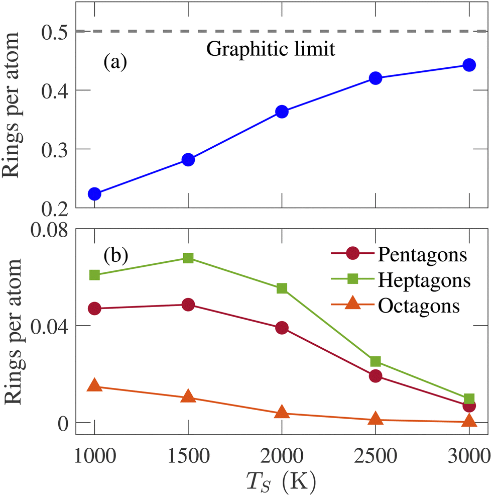 | ||
| Fig. 4 Variation of (a) hexagonal, (b) pentagonal, heptagonal, and octagonal rings per atom with the simulation temperature (TS). | ||
Fig. 4(b) shows the fraction of non-hexagonal rings for different temperatures. The octagonal ring fraction remains small at low temperatures and tends to zero at high temperatures. Therefore, rings larger than octagons were not counted as their percentages were too insignificant. The percentage of the heptagonal ring is slightly greater than the pentagonal ring, especially when TS ≤ 2000 K. Different percentages of the pentagonal and heptagonal rings indicate the presence of curved graphene sheets, consistent with the observation in Fig. 3. The pentagonal and heptagonal ring counts are almost equal at TS = 2500 and 3000 K. If the number of pentagons and heptagons are equal, there will be no spherical curvature according to Euler criteria.45Fig. 3(i) and (j) show that large and planar graphene sheets are formed with small curvatures at TS = 2500 and 3000 K. The difference between heptagonal and pentagonal rings is the smallest at TS = 3000 K, resulting in the largest flat graphene sheet formation among all the structures generated in this work.
The pair distribution function (PDF) represents the number of atoms in a spherical shell with a radius of r, centering a reference atom and averaging over all atoms. Eqn (1) can be written as G(r) = 4πr[ρ(r) − ρ0], where ρ0 and ρ(r) are the average and local atom densities, respectively, at a distance r. As evident from the equation, the PDF oscillates around zero and shows prominent peaks at distances corresponding to distances between atoms.63 The negative value of PDF represents that the local density at that distance is smaller than the average density. Fig. 5 shows the PDFs of simulated structures for r ≤ 10 Å, annealed at different annealing temperatures. The positions of the peaks in these PDFs resemble that of an ideal graphene structure, indicating the graphitic nature of these structures and supporting the observations from previous results. The peaks appearing at 1.43, 2.47, and 2.83 Å correspond to the first, second, and third nearest neighbors in a graphene structure composed of hexagonal rings. Subsequent peaks at 3.78, 4.27, and 4.95 Å are representatives of atoms in neighboring hexagonal rings. The peak at 5.15 Å is only visible at TS ≥ 2500 K. With increasing temperature, the peaks become narrower and more prominent, indicating a higher degree of graphitization with the temperature rise. The structure annealed at 3000 K is the most graphitic as the long-range order is observed with the presence of narrow and visible peaks beyond 6 Å, as shown in Fig. 5. The small peak observed at 3.2 Å is due to the presence of heptagonal rings in the simulated structures.64
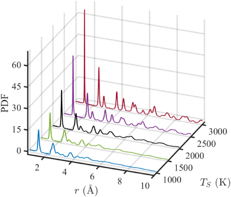 | ||
| Fig. 5 Pair distribution function (PDF) for simulated structures annealed at five simulation temperatures (TS). | ||
The simulated PDFs are compared with the experimentally determined X-ray diffraction PDFs obtained by Forse et al.64 In Fig. 6, PDFs of experimental samples synthesized at 600, 800, and 1000 °C are compared with the calculated PDFs annealed at 1500, 2000, and 2500 K, respectively. The correspondence between TS and Te has been established by the Arrhenius relation. Excellent agreement between the simulated and experimental data has been observed in the positions and heights of the peaks, except for the third peak at 2.88 Å. Nevertheless, this degree of conformity to experimental PDF over three different temperatures has never been reported in the literature. With increasing temperature, the peaks of the experimental PDFs become more pronounced, and a similar trend is observed in the simulated PDFs. At TS = 2500 K, although the third simulated PDF peak occurs at the same position as the experimental PDF, the heights do not match. In a recent work by de Tomas et al.,45 good agreement between the simulated and the experimental PDFs corresponding to the CDC sample synthesized at 1000 °C was reported but failed to reproduce the peaks beyond 4 Å for the experimental sample of 600 °C. On the other hand, the PDF of the simulated structure corresponding to 600 °C from this work accurately reproduces the numbers and positions of peaks beyond 4 Å, as shown in Fig. 6(a).
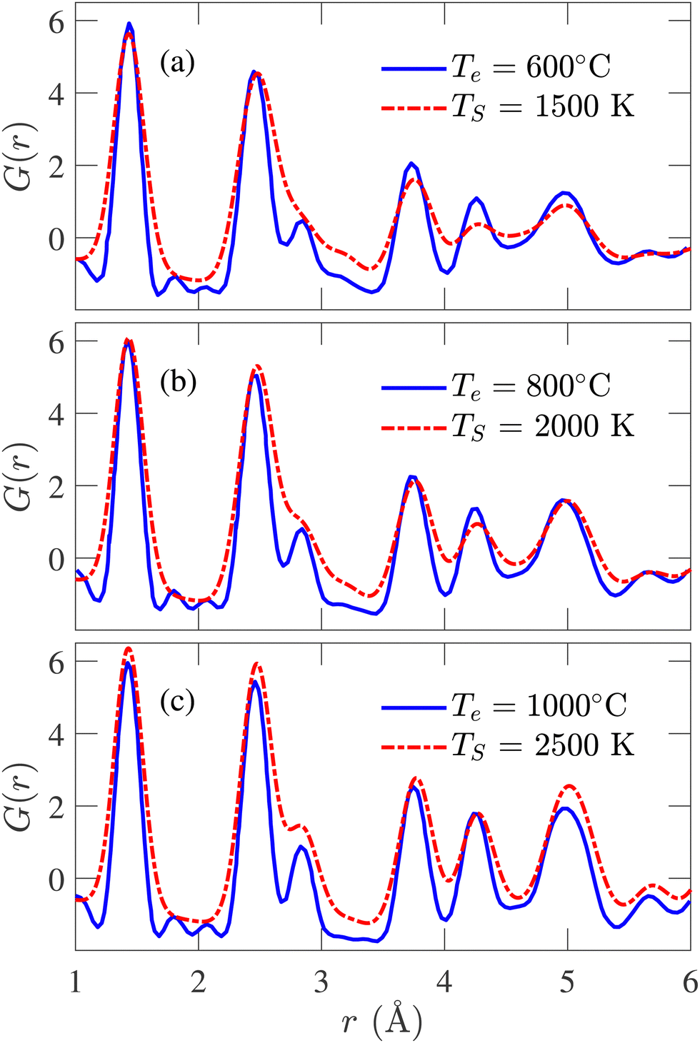 | ||
| Fig. 6 Comparison between simulated and experimental pair distribution functions (PDFs) obtained from X-ray diffraction for simulation temperature (TS) of (a) 1500 K, (b) 2000 K, and (c) 2500 K. The experimental results are reported by Forse et al.64 | ||
Fig. 7 presents the sp2-hybridized atom percentage variations with TS. An increasing trend in the sp2-bonded atom percentage is evident from the figure, reaching 98.3% at TS = 3000 K. The sp3-bonded atom percentage remains <2% for all structures. The sp-bonded atom percentage decreases from 21% to 1.60% as TS increases from 1000 to 3000 K. The average coordination number for the simulated structures varies from 2.80 to 2.98, agreeing well with the previously reported variations from 2.95 to 3.05 by de Tomas et al.45 The large sp2-percentage indicates the graphitic nature of the annealed structures and reveals a higher degree of graphitization with increasing temperature. Experimentally determined sp2 data available in literature20 for temperatures corresponding to the simulation temperatures are also plotted in Fig. 7 for comparison. The experimental data for 400 °C is not available in the literature and could not be compared with the simulated result. Good agreement is observed at the high-temperature range, while deviation is observed in the low-temperature range. The experimental data spanning the temperature range from 500 °C to 3000 °C show an overall increasing trend. Such an increasing trend is also seen in our data; however, the experimental temperature range to which our data is compared does not exhibit a strong increasing trend.
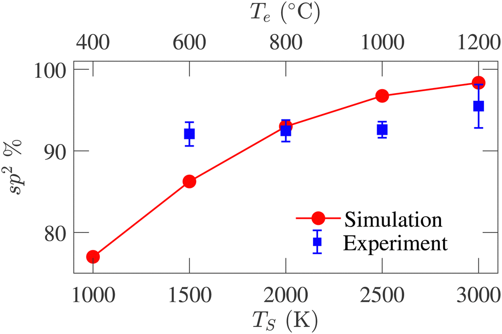 | ||
| Fig. 7 Comparison between sp2-hybridized atom percentage variations with simulation (TS) and experiment (Te) temperatures. The experimental data are reported by Gläsel et al.20 | ||
Adsorption isotherm is an integral property of the CDC sample as it is used for determining PSD experimentally. In an experimental setup, N2, CO2, CH4 gases can be adsorbed in the porous structure to calculate the adsorption isotherm. To reduce simulation run-time, adsorption isotherm is calculated from Ar gas adsorption in simulated porous models, as the Ar molecule consists of only one atom. GCMC simulated argon adsorption isotherms at 77 K are compared with the experimental data reported by Dash et al.6 Conventionally, adsorption isotherm is plotted against relative pressure (P/P0) where P0 is the saturation pressure, beyond which the adsorbate volume does not increase with an increase in pressure. The results in Fig. 8 are given assuming P0 = 1 atm.
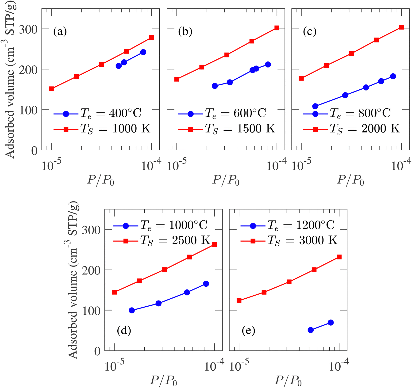 | ||
| Fig. 8 Comparison between the experimental and GCMC simulation generated argon adsorption isotherm at 77 K and low-pressure region for structures developed at different temperatures. The experimental data is reported by Dash et al.6 | ||
The isotherms calculated from experimental CDC samples exhibit increasing adsorbed volume of argon at P/P0 = 1 with increasing synthesis temperature Te. A similar trend is observed for simulated carbon structures where the absorbed volume gradually increases from 432 to 513 cm3 g−1 as TS changes from 1000 to 3000 K. The slight increase in pore volume with temperature is also reflected by the porosity, i.e., the ratio of void space to the total volume of a system. The calculated porosity is in very close agreement with the experimentally reported 57%,1 albeit the variation between 57.6% and 61.7% for TS of 1000 and 3000 K, respectively. The simulated adsorption at a high relative pressure does not match the experimental data. This deviation can be attributed to the heterogeneous nature and considerable density variation in experimental samples with length scale inaccessible by MD simulation. On the other hand, at a low-pressure regime, due to the low density of adsorbate, carbon argon interaction should be the principal influence on adsorption.21 As a result, while it is not possible to achieve quantitative conformity at high relative pressure between experimental and simulated isotherms, qualitative comparison at low-pressure regimes should be feasible. The comparison between simulated and experimental adsorption isotherms at low relative pressure regions is presented in Fig. 8. The strong adsorption at low-pressure regions indicates the presence of micropores in simulated structures. At TS = 1000 K, the simulated isotherm slightly overestimates the experimental value while maintaining an identical trend. For TS < 2500 K, the isotherms shift slightly upwards with increasing simulation temperature, failing to capture the trend observed in experiments. For TS > 2500 K, the isotherms shift downwards with temperature, conforming to the experimental observation and indicating reduced pore volume in the micropore regime.
Fig. 9 represents the normalized geometric PSD, calculated following the method of Gleb and Gubbins.36 It is evident that the largest diameter of pores in the distribution is proportional to the annealing temperature. A similar trend can be observed in the cross-sectional snapshot shown in Fig. 3, where the emergence of pores with larger sizes is visually observed with increasing simulation temperature. The PSD gradually shifts rightward as TS increases. At TS = 1000 K, the PSD is narrow with a relatively small dispersion. With increasing temperature, more dispersed PSD is observed, extending up to 34 Å at TS = 3000 K. For TS < 2000 K, the pore size is confined in the micropore regime, i.e., <20 Å. For TS > 2000 K, the PSD extends into the mesopore regime. The formation of mesopores justifies the necessity of a large system size for simulation, as implemented in this work.
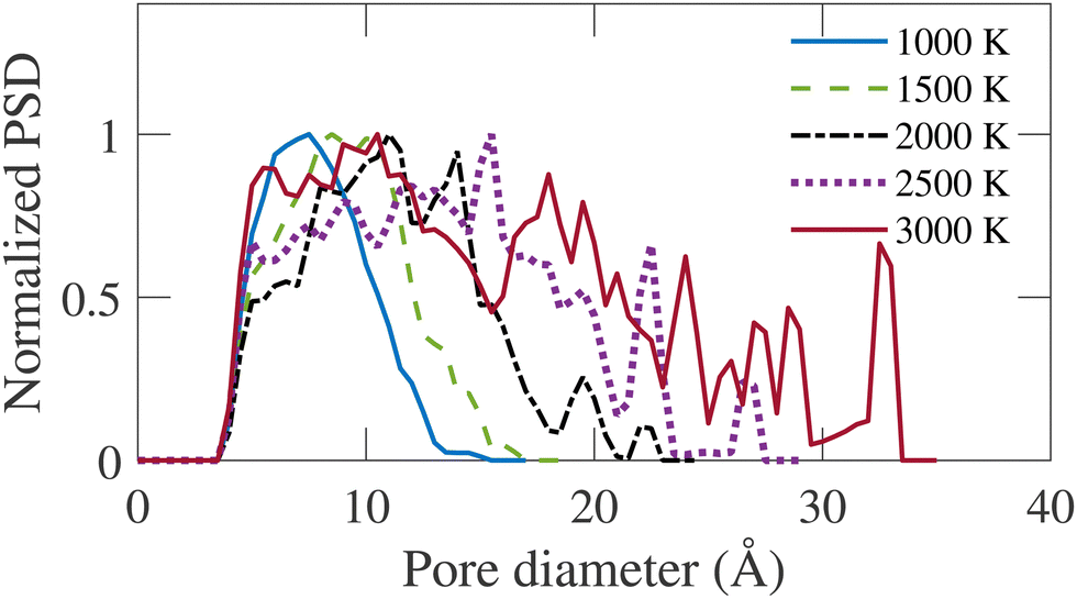 | ||
| Fig. 9 Normalized pore size distribution (PSD) for annealed structures at different simulation temperatures (TS). | ||
Experimentally, the PSD cannot be determined directly from the samples. The experimental pore size reported by Dash et al.6 is calculated using the non-local density functional theory (NLDFT) from the argon adsorption isotherm at 77 K and carbon dioxide adsorption isotherm at 273 K. As the simulated PSD and experimental PSD are calculated using different methodologies, they have not been compared directly. However, the variation of average pore diameter with simulation and corresponding experimental temperature is shown in Fig. 10. The average geometric pore size overestimates the experimental data. In addition, in experimental samples, a decrease in the average pore diameter is observed as the temperature increases from 400 to 600 °C. Apart from this temperature range, the simulated average pore diameter follows the increasing trend of the experimental average pore size. The offset between the experimental and simulated data is attributed to the difference in methodologies for calculating PSD. Notably, the PSD calculated using the NLDFT method depends on the adsorbate molecule's size, while geometric PSD has no such dependency.
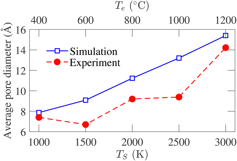 | ||
| Fig. 10 Comparison between the variation of average pore size of experimental samples and simulated structures with temperature. The experimental data are obtained from ref. 6. | ||
4 Conclusion
This work has reported the first application of ABOP in generating structurally realistic CDC models. Simulations carried out with large simulation boxes and for long simulation time have resulted in carbon models with realistic structural features, which have been compared with the experimentally generated TiC-CDC samples. Annealing with higher temperatures and longer simulation time have resulted in more ordered and graphitized carbon structures. The Arrhenius model has been applied to formulate a one-to-one relation between simulation and experimental temperatures. The comparison between TEM images and cross-sectional snapshots of the simulated structures reveals the structural similarity between experimental and simulated samples. The simulated structures in this work exhibit the same trend in the variation of structural parameters as the experimental structures as the temperature increases. Although our simulated models have a higher degree of graphene sheet stacking than previous quench-generated models, they still need to be in the order of experimental samples. The adsorption isotherms in the low-pressure region indicate that the structures are populated with many micropores, which agrees with experiments qualitatively. Despite a few limitations, the carbon model generated in the annealing methodology in our work has more realistic features than any other quench-generated models reported previously. Furthermore, due to the low computational cost of ABOP forcefield, larger systems can be simulated for a long simulation time, and realistic carbon structures can be produced and analyzed swiftly. Realistic carbon models with porous carbon electrodes are essential for supercapacitor simulation studies. The porous carbon model generated in our work could be applied to study the non-ideal effects of the surface curvature, spatial distribution of pores, and pore accessibility of ions on supercapacitor device performances.Data availability statement
Data for this article, i.e., the XYZ files comprising the atomic coordinate of simulated models are available at https://doi.org/10.5281/zenodo.11396617.Conflicts of interest
There are no conflicts to declare.References
- V. Presser, M. Heon and Y. Gogotsi, Carbide-derived carbons-from porous networks to nanotubes and graphene, Adv. Funct. Mater., 2011, 21(5), 810–833 CrossRef CAS.
- Y. Gogotsi, A. Nikitin, H. Ye, W. Zhou, J. E. Fischer, B. Yi, H. C. Foley and M. W. Barsoum, Nanoporous carbide-derived carbon with tunable pore size, Nat. Mater., 2003, 2(9), 591–594 CrossRef CAS PubMed.
- S. Osswald, J. Chmiola and Y. Gogotsi, Structural evolution of carbide-derived carbons upon vacuum annealing, Carbon, 2012, 50(13), 4880–4886 CrossRef CAS.
- G. Laudisio, R. K. Dash, J. P. Singer, G. Yushin, Y. Gogotsi and J. E. Fischer, Carbide-derived carbons: a comparative study of porosity based on small-angle scattering and adsorption isotherms, Langmuir, 2006, 22(21), 8945–8950 CrossRef CAS PubMed.
- S. Welz, M. J. McNallan and Y. Gogotsi, Carbon structures in silicon carbide derived carbon, J. Mater. Process. Technol., 2006, 179(1–3), 11–22 CrossRef CAS.
- R. Dash, J. Chmiola, G. Yushin, Y. Gogotsi, G. Laudisio, J. Singer, J. Fischer and S. Kucheyev, Titanium carbide derived nanoporous carbon for energy-related applications, Carbon, 2006, 44(12), 2489–2497 CrossRef CAS.
- E. N. Hoffman, G. Yushin, T. El-Raghy, Y. Gogotsi and M. W. Barsoum, Micro and mesoporosity of carbon derived from ternary and binary metal carbides, Microporous Mesoporous Mater., 2008, 112(1–3), 526–532 CrossRef CAS.
- R. Dash, G. Yushin and Y. Gogotsi, Synthesis, structure and porosity analysis of microporous and mesoporous carbon derived from zirconium carbide, Microporous Mesoporous Mater., 2005, 86(1–3), 50–57 CrossRef CAS.
- J. Chmiola, G. Yushin, Y. Gogotsi, C. Portet, P. Simon and P.-L. Taberna, Anomalous increase in carbon capacitance at pore sizes less than 1 nanometer, Science, 2006, 313(5794), 1760–1763 CrossRef CAS PubMed.
- J. Chmiola, G. Yushin, R. Dash and Y. Gogotsi, Effect of pore size and surface area of carbide derived carbons on specific capacitance, J. Power Sources, 2006, 158(1), 765–772 CrossRef CAS.
- R. Lin, P. Huang, J. Segalini, C. Largeot, P.-L. Taberna, J. Chmiola, Y. Gogotsi and P. Simon, Solvent effect on the ion adsorption from ionic liquid electrolyte into sub-nanometer carbon pores, Electrochim. Acta, 2009, 54(27), 7025–7032 CrossRef CAS.
- J. Chmiola, C. Largeot, P.-L. Taberna, P. Simon and Y. Gogotsi, Monolithic carbide-derived carbon films for micro-supercapacitors, Science, 2010, 328(5977), 480–483 CrossRef CAS PubMed.
- S. Yachamaneni, G. Yushin, S.-H. Yeon, Y. Gogotsi, C. Howell, S. Sandeman, G. Phillips and S. Mikhalovsky, Mesoporous carbide-derived carbon for cytokine removal from blood plasma, Biomaterials, 2010, 31(18), 4789–4794 CrossRef CAS PubMed.
- C. Vakifahmetoglu, V. Presser, S.-H. Yeon, P. Colombo and Y. Gogotsi, Enhanced hydrogen and methane gas storage of silicon oxycarbide derived carbon, Microporous Mesoporous Mater., 2011, 144(1–3), 105–112 CrossRef CAS.
- V. Presser, J. McDonough, S.-H. Yeon and Y. Gogotsi, Effect of pore size on carbon dioxide sorption by carbide derived carbon, Energy Environ. Sci., 2011, 4(8), 3059–3066 RSC.
- A. M. Kern, B. Zierath, J. Haertlé, T. Fey and B. J. Etzold, Thermal and electrical conductivity of amorphous and graphitized carbide-derived carbon monoliths, Chem. Eng. Technol., 2016, 39(6), 1121–1129 CrossRef CAS.
- S. Kondrat, P. Wu, R. Qiao and A. A. Kornyshev, Accelerating charging dynamics in subnanometre pores, Nat. Mater., 2014, 13(4), 387–393 CrossRef CAS PubMed.
- Y. He, J. Huang, B. G. Sumpter, A. A. Kornyshev and R. Qiao, Dynamic charge storage in ionic liquids-filled nanopores: insight from a computational cyclic voltammetry study, J. Phys. Chem. Lett., 2015, 6(1), 22–30 CrossRef CAS PubMed.
- G. Yushin, R. Dash, J. Jagiello, J. E. Fischer and Y. Gogotsi, Carbide-derived carbons: effect of pore size on hydrogen uptake and heat of adsorption, Adv. Funct. Mater., 2006, 16(17), 2288–2293 CrossRef CAS.
- J. Gläsel, J. Diao, Z. Feng, M. Hilgart, T. Wolker, D. S. Su and B. J. Etzold, Mesoporous and graphitic carbide-derived carbons as selective and stable catalysts for the dehydrogenation reaction, Chem. Mater., 2015, 27(16), 5719–5725 CrossRef.
- J. Palmer, A. Llobet, S.-H. Yeon, J. Fischer, Y. Shi, Y. Gogotsi and K. Gubbins, Modeling the structural evolution of carbide-derived carbons using quenched molecular dynamics, Carbon, 2010, 48(4), 1116–1123 CrossRef CAS.
- P. J. Harris, Structure of non-graphitising carbons, Int. Mater. Rev., 1997, 42(5), 206–218 CrossRef CAS.
- P. J. Harris and S. C. Tsang, High-resolution electron microscopy studies of non-graphitizing carbons, Philos. Mag. A, 1997, 76(3), 667–677 CAS.
- M. Acharya, M. S. Strano, J. P. Mathews, S. J. Billinge, V. Petkov, S. Subramoney and H. C. Foley, Simulation of nanoporous carbons: a chemically constrained structure, Philos. Mag. B, 1999, 79(10), 1499–1518 CrossRef CAS.
- G. Feng, R. Qiao, J. Huang, S. Dai, B. G. Sumpter and V. Meunier, The importance of ion size and electrode curvature on electrical double layers in ionic liquids, Phys. Chem. Chem. Phys., 2011, 13(3), 1152–1161 RSC.
- J. C. Palmer, J. D. Moore, J. K. Brennan and K. E. Gubbins, Simulating local adsorption isotherms in structurally complex porous materials: A direct assessment of the slit pore model, J. Phys. Chem. Lett., 2011, 2(3), 165–169 CrossRef CAS.
- R. McGreevy and L. Pusztai, Reverse monte carlo simulation: a new technique for the determination of disordered structures, Mol. Simul., 1988, 1(6), 359–367 CrossRef.
- S. Duane, A. D. Kennedy, B. J. Pendleton and D. Roweth, Hybrid monte carlo, Phys. Lett. B, 1987, 195(2), 216–222 CrossRef CAS.
- S. K. Jain, R. J.-M. Pellenq, J. P. Pikunic and K. E. Gubbins, Molecular modeling of porous carbons using the hybrid reverse monte carlo method, Langmuir, 2006, 22(24), 9942–9948 CrossRef CAS PubMed.
- G. Opletal, T. Petersen, D. McCulloch, I. Snook and I. Yarovsky, The structure of disordered carbon solids studied using a hybrid reverse monte carlo algorithm, J. Phys.: Condens. Matter, 2005, 17(17), 2605 CrossRef CAS.
- P. Zetterström, S. Urbonaite, F. Lindberg, R. G. Delaplane, J. Leis and G. Svensson, Reverse monte carlo studies of nanoporous carbon from tic, J. Phys.: Condens. Matter, 2005, 17(23), 3509 CrossRef.
- P. Kowalczyk, A. P. Terzyk, P. A. Gauden, S. Furmaniak, M. Wisśniewski, A. Burian, L. Hawelek, K. Kaneko and A. V. Neimark, Carbon molecular sieves: reconstruction of atomistic structural models with experimental constraints, J. Phys. Chem. C, 2014, 118(24), 12996–13007 CrossRef CAS.
- P. Jedlovszky, I. Bakó, G. Palinkas, T. Radnai and A. Soper, Investigation of the uniqueness of the reverse monte carlo method: Studies on liquid water, J. Chem. Phys., 1996, 105(1), 245–254 CrossRef CAS.
- S. H. Garofalini, Molecular dynamics simulation of the frequency spectrum of amorphous silica, J. Chem. Phys., 1982, 76(6), 3189–3192 CrossRef CAS.
- M. D. Kluge, J. R. Ray and A. Rahman, Amorphous-silicon formation by rapid quenching: A molecular-dynamics study, Phys. Rev. B: Condens. Matter Mater. Phys., 1987, 36(8), 4234 CrossRef CAS PubMed.
- L. D. Gelb and K. Gubbins, Pore size distributions in porous glasses: a computer simulation study, Langmuir, 1999, 15(2), 305–308 CrossRef CAS.
- K. Ding and H. C. Andersen, Molecular-dynamics simulation of amorphous germanium, Phys. Rev. B: Condens. Matter Mater. Phys., 1986, 34(10), 6987 CrossRef CAS PubMed.
- Y. Shi, A mimetic porous carbon model by quench molecular dynamics simulation, J. Chem. Phys., 2008, 128(23), 234707 CrossRef PubMed.
- J. Tersoff, Modeling solid-state chemistry: Interatomic potentials for multicomponent systems, Phys. Rev. B: Condens. Matter Mater. Phys., 1989, 39(8), 5566 CrossRef PubMed.
- A. C. Van Duin, S. Dasgupta, F. Lorant and W. A. Goddard, Reaxff: a reactive force field for hydrocarbons, J. Phys. Chem. A, 2001, 105(41), 9396–9409 CrossRef CAS.
- M. W. Thompson, B. Dyatkin, H.-W. Wang, C. H. Turner, X. Sang, R. R. Unocic, C. R. Iacovella, Y. Gogotsi, A. C. Van Duin and P. T. Cummings, An atomistic carbide-derived carbon model generated using reaxff-based quenched molecular dynamics, C, 2017, 3(4), 32 Search PubMed.
- R. Ranganathan, S. Rokkam, T. Desai and P. Keblinski, Generation of amorphous carbon models using liquid quench method: A reactive molecular dynamics study, Carbon, 2017, 113, 87–99 CrossRef CAS.
- M. J. López, I. Cabria and J. A. Alonso, Simulated porosity and electronic structure of nanoporous carbons, J. Chem. Phys., 2011, 135(10), 104706 CrossRef PubMed.
- N. A. Marks, Generalizing the environment-dependent interaction potential for carbon, Phys. Rev. B: Condens. Matter Mater. Phys., 2000, 63(3), 035401 CrossRef.
- C. de Tomas, I. Suarez-Martinez, F. Vallejos-Burgos, M. J. Lopez, K. Kaneko and N. A. Marks, Structural prediction of graphitization and porosity in carbide-derived carbons, Carbon, 2017, 119, 1–9 CrossRef CAS.
- C. de Tomas, A. Aghajamali, J. L. Jones, D. J. Lim, M. J. Lopez, I. Suarez-Martinez and N. A. Marks, Transferability in interatomic potentials for carbon, Carbon, 2019, 155, 624–634 CrossRef CAS.
- D. Pettifor and I. Oleinik, Analytic bond-order potentials beyond tersoff-brenner. i. theory, Phys. Rev. B: Condens. Matter Mater. Phys., 1999, 59(13), 8487 CrossRef CAS.
- X. Zhou, D. K. Ward and M. E. Foster, An analytical bond-order potential for carbon, J. Comput. Chem., 2015, 36(23), 1719–1735 CrossRef CAS PubMed.
- S. Winczewski, M. Y. Shaheen and J. Rybicki, Interatomic potential suitable for the modeling of penta-graphene: Molecular statics/molecular dynamics studies, Carbon, 2018, 126, 165–175 CrossRef CAS.
- J. Yan and S. Chen, Mechanical properties of monolayer antimony carbide: A molecular dynamics simulation, Mater. Today Commun., 2020, 22, 100817 CrossRef CAS.
- L. R. Safina, E. A. Rozhnova, R. T. Murzaev and J. A. Baimova, Effect of interatomic potential on simulation of fracture behavior of cu/graphene composite: A molecular dynamics study, Appl. Sci., 2023, 13(2), 916 CrossRef CAS.
- V. L. Deringer and G. Csányi, Machine learning based interatomic potential for amorphous carbon, Phys. Rev. B, 2017, 95(9), 094203 CrossRef.
- Y. Wang, Z. Fan, P. Qian, T. Ala-Nissila and M. A. Caro, Structure and pore size distribution in nanoporous carbon, Chem. Mater., 2022, 34(2), 617–628 CrossRef CAS.
- S. Plimpton, Fast parallel algorithms for short-range molecular dynamics, J. Comput. Phys., 1995, 117(1), 1–19 CrossRef CAS.
- G. Bussi, D. Donadio and M. Parrinello, Canonical sampling through velocity rescaling, J. Chem. Phys., 2007, 126(1), 014101 CrossRef PubMed.
- A. Stukowski, Visualization and analysis of atomistic simulation data with ovito-the open visualization tool, Modell. Simul. Mater. Sci. Eng., 2009, 18(1), 015012 CrossRef.
- D. Franzblau, Computation of ring statistics for network models of solids, Phys. Rev. B: Condens. Matter Mater. Phys., 1991, 44(10), 4925 CrossRef CAS PubMed.
- S. Bhattacharya and K. E. Gubbins, Fast method for computing pore size distributions of model materials, Langmuir, 2006, 22(18), 7726–7731 CrossRef CAS PubMed.
- J. K. Shah, E. Marin-Rimoldi, R. G. Mullen, B. P. Keene, S. Khan, A. S. Paluch, N. Rai, L. L. Romanielo, T. W. Rosch, B. Yoo, et al., Cassandra: An open source monte carlo package for molecular simulation, 2017 Search PubMed.
- B. Coasne, S. K. Jain, L. Naamar and K. E. Gubbins, Freezing of argon in ordered and disordered porous carbon, Phys. Rev. B: Condens. Matter Mater. Phys., 2007, 76(8), 085416 CrossRef.
- W. A. Steele, The interaction of rare gas atoms with graphitized carbon black, J. Phys. Chem., 1978, 82(7), 817–821 CrossRef CAS.
- N. Marks, M. Cover and C. Kocer, Simulating temperature effects in the growth of tetrahedral amorphous carbon: the importance of infrequent events, Appl. Phys. Lett., 2006, 89(13), 131924 CrossRef.
- V. Petkov, Pair distribution functions analysis, Characterization of Materials, 2012, pp. 1361–1372 Search PubMed.
- A. C. Forse, C. Merlet, P. K. Allan, E. K. Humphreys, J. M. Griffin, M. Aslan, M. Zeiger, V. Presser, Y. Gogotsi and C. P. Grey, New insights into the structure of nanoporous carbons from NMR, Raman, and pair distribution function analysis, Chem. Mater., 2015, 27(19), 6848–6857 CrossRef CAS.
| This journal is © The Royal Society of Chemistry 2024 |