
 Open Access Article
 This Open Access Article is licensed under a
 Creative Commons Attribution 3.0 Unported Licence
Microporous carbonaceous adsorbent prepared from a pyrolyzed polymer†
Jaroslav
Lang
 *a,
Jan
Bednárek
a,
Michal
Ritz
b,
Martin
Kormunda
c,
Tomáš
Zelenka
d,
Michal
Vaštyl
a,
Anna
Gavlová
a,
Zdeňka
Kolská
c and
Marta
Férová
d
*a,
Jan
Bednárek
a,
Michal
Ritz
b,
Martin
Kormunda
c,
Tomáš
Zelenka
d,
Michal
Vaštyl
a,
Anna
Gavlová
a,
Zdeňka
Kolská
c and
Marta
Férová
d
aInstitute of Environmental Technology, CEET, VSB – Technical University of Ostrava, 17. Listopadu 2172/15, 708 00 Ostrava-Poruba, Czech Republic. E-mail: jaroslav.lang@vsb.cz
bFaculty of Materials Science and Technology, Department of Chemistry and Physico-Chemical Processes, VSB – Technical University of Ostrava, 17. Listopadu 2172/15, 708 00 Ostrava-Poruba, Czech Republic
cFaculty of Science, J. E. Purkyně University, Pasteurova 15, 400 96 Ústí nad Labem, Czech Republic
dFaculty of Science, University of Ostrava, 30. dubna 22, 701 03 Ostrava, Czech Republic
First published on 16th July 2024
Abstract
Emerging pollutants pose a significant health risk, and their presence in water has far-reaching consequences. Although there are several ways to decrease the levels of emerging contaminants, conventional water treatment processes are not designed for their removal. One of the more effective water treatment methods used for further micropollutant elimination is adsorption on carbonaceous materials. This work focuses on the preparation of a carbonaceous adsorbent using the pyrolysis of the polymer polyetheretherketone (PEEK). The polymer was pyrolyzed at 600 °C for 3 hours in an N2 atmosphere. The prepared carbonaceous material is microporous and contains surface oxygen functional groups (ethers, ketones, and aldehydes). The adsorption properties of the prepared adsorbent were tested on two pharmaceuticals: the analgesic diclofenac and antibiotic ofloxacin. In this study, kinetic and equilibrium experiments were performed. The adsorption maximum was 2.25 mg g−1 for diclofenac and 2.84 mg g−1 for ofloxacin. The pseudo-second-order model and Redlich–Peterson model best fitted both diclofenac and ofloxacin. The prepared material did not show high adsorption capacity, but the potential of the polymers as a feedstock material for pyrolysis was successfully demonstrated. This research might serve as a stepping stone towards the preparation of tailor-made adsorbents that could be used for studying adsorption mechanisms.
Introduction
Anthropogenic pollution is a major global issue, and its consequences for human life, and life on this planet in general, are yet to be determined. The main contributors to man-made pollution are agriculture and various kinds of industries, such as pharmaceutical, textile, chemical, and energy. The adverse effects and health risks on human health linked to man-made pollution include poisoning, changes in metabolism, and even cancer, but the negative effects on the aquatic life and biota in general are non-negligible as well.1–3 New, or previously undetectable, emerging pollutants (EPs) are now becoming more prevalent. A significant number of EPs are present in the aquatic environment.4 These are mainly pharmaceuticals and personal care products (PPCPs), endocrine-disrupting compounds (EDCs), pesticides, flame retardants, surfactants, nanoparticles, and illicit drugs.5 Although these compounds are present at relatively low concentrations (ng mL−1 or μg mL−1), EPs such as hormones, pyrethroids, and certain organophosphorus pesticides, can affect the aquatic environment even at extremely low doses.4Accumulation of pharmaceuticals in wastewater is a growing global concern, and the removal of pharmaceuticals represents an environmental challenge that has to be faced. Two common pharmaceutical compounds used on a daily basis were used in this work. Diclofenac is a non-prescription non-steroidal anti-inflammatory drug (NSAID) with analgesic and antipyretic activity. It is used, e.g., for the treatment of rheumatoid arthritis or to alleviate muscle, joint, or menstrual pain. However, this substance has a documented negative impact on the environment.6,7 Ofloxacin is a fluoroquinolone antibiotic with a broad spectrum of uses, e.g. urinary and respiratory tract infections, otitis, or conjunctivitis. It is partly resistant to conventional wastewater treatment and can be dangerous for aquatic organisms.8 Both these compounds are commonly present in wastewater. In the literature, ofloxacin concentrations ranging from 5 ng L−1 to 160 μg L−1![[thin space (1/6-em)]](https://www.rsc.org/images/entities/char_2009.gif) 9,10 and diclofenac concentrations ranging from 0.04 ng L−1 to 11 mg L−1 have been reported.11,12 In order to draw near these real-life concentrations in our study, we chose concentrations in the μg L−1 range for kinetics experiments.
9,10 and diclofenac concentrations ranging from 0.04 ng L−1 to 11 mg L−1 have been reported.11,12 In order to draw near these real-life concentrations in our study, we chose concentrations in the μg L−1 range for kinetics experiments.
Although there are several ways to decrease the levels of emerging contaminants, conventional wastewater treatment processes are not designed to remove these micropollutants. Therefore, several methods for water purification are being investigated, e.g., advanced oxidation processes (AOP),13 reverse osmosis,14 biological treatment,15 adsorption, etc. The AOP can degrade both organic and inorganic pollutants showing high removal efficiency, and methods like ozonization and Fenton processes are well described. On the other hand, generally requiring pre-treatment steps, there is a risk of the formation of toxic and harmful by-products and the economic viability of these methods is low at the moment.13 Reverse osmosis also removes organic and inorganic pollutants, produces high-quality water, and can be economically feasible with minimal pre-treatment steps. Although some pre-treatment is still needed, the membranes are prone to fouling, and the use of aggressive chemical cleaning lowers the lifetime.14 The biological treatment methods are already used in wastewater treatment plants, mainly used for the degradation of organic pollutants, and are more economically and environmentally viable options. The removal efficiency is not very high and greatly depends on the nature of the pharmaceutical pollutant.16,17 The popularity of adsorption lies in its effectiveness for a variety of pollutants, efficiency, and economy.18 Due to their high efficiency, carbonaceous materials (activated carbon and biochar) are among the most popular adsorbents.19 Common precursors for their preparation are coal, peat, lignite, coconut shells, etc.20 In the last years, the use of alternative precursors, such as various agricultural waste21–25 or invasive herbs,26–28 gained attention. Activated carbon and biochar are commonly used for the adsorption of a great variety of organic substances29–32 and heavy metals,30–33 and it should be pointed out that they are able to remove the EPs.5,34,35
The surface functional groups and textural properties of an adsorbent play a key role in adsorption. It is desirable to use materials with a large surface area, suitable pore size distribution, and surface chemistry (surface functional groups favoring adsorption of the intended pollutant). Of the variety of functional groups, oxygen functional groups play a major role in the adsorption of polar substances (pesticides, pharmaceuticals, industrial chemicals).4
The standard pyrolysis feedstock for activated carbon and biochar is biomass, coal, and petroleum pitch, which are chemically very diverse cocktails of various substances. Plant biomass is a very complicated composite mixture of polymers, inorganic and organic compounds with complex morphology (tissues, vascular system, etc.). With such a complex feedstock, the product is always a mixture of different functional groups and large pore distribution. Polymers represent a suitable resource of carbonaceous material with uniform chemical composition and well-described chemical structure with an option for further targeted modifications. These features make polymers an excellent pyrolysis feedstock, and would allow for the preparation of tailor-made adsorbents.
The research on the synthesis and preparation of adsorbents with specific functional groups derived from polymer pyrolysis feedstock is very limited compared to activated carbon and biochar.36–38 Their variable chemical composition and morphology allow for better control over the parameters of the produced carbonaceous material.39,40 Polymer-based activated carbon made of waste PVC and PET exhibited high adsorption capacity.41 Some recent works focused on using polymer-based carbonaceous materials for water treatment. Al-Odayini42 studied the adsorption of methyl orange on polyaniline-based activated carbon. Trinh and Schäfer43 used polymer-based spherical activated carbon (PSBAC) for the adsorption of glyphosate and its metabolite aminomethylphosphonic acid (AMPA). PSBAC was also used for the removal of steroids in work by Tagliavini et al.44 It should be noted that similar requirements on the textural parameters and functional groups of adsorbents are the same for electrode materials. The use of pyrolyzed polymer electrodes in supercapacitors is very promising.45
PEEK is a high-performance polymer with applications in the aerospace and car industry. It is chemically and thermally stable up to 250 °C without any loss of mechanical properties, and can be further reinforced by the addition of carbon and glass fibers. As a thermoplastic, it can be melted and reused. The processing involves grinding, melting, and subsequent injection molding. The process can be repeated several times before the mechanical properties of the polymer are diminished.46 The chemical and thermal stability previously desired in the material then poses a disadvantage during the recycling process. The material ends up in a landfill or requires complicated disposal methods.47 An alternative would be to use discarded PEEK as a feedstock for thermal processing. The pyrolysis-prepared carbonaceous material could be used as an adsorbent for pollutants and/or as an electrode material.
The main objective of this work was to prepare a carbonaceous material by pyrolysis from polymeric raw materials and characterize the new carbonaceous material, both in terms of the material morphology and functional groups on the surface of the material. The study was supplemented by the adsorption properties of the carbonaceous material. The adsorption properties were tested on two pharmaceuticals commonly found in wastewater – the analgesic diclofenac and the antibiotic ofloxacin.
Materials and methods
The following commercially available polymers—polystyrene (PS), copolymer ethylene-norbornene (COC), polyetheretherketone (PEEK), and polycarbonate (PC) were used in the initial assessment. Pristine polyetheretherketone (PEEK) polymer was provided by Xiamen Keyuan Plastic Co., Ltd. The polymer structures are listed in the ESI† (Table S1). The initial assessment of the polymers was done using thermogravimetric analysis (TGA). The pristine PEEK was further characterized using X-ray powder diffraction (XRD), X-ray fluorescence spectrometry (XRF), and Fourier transform infrared spectroscopy (FTIR). The XRF results for PEEK can be found in the Table S2 (ESI†). The PEEK material was used in pyrolysis experiments as received without additional processing. The pyrolysis of the polymer material was performed using TGA instrumentation.The pharmaceuticals diclofenac sodium salt and ofloxacin (Sigma Aldrich, St. Louis, MO, USA) (Table 1) were used in adsorption experiments.
| Pharmaceuticals | Diclofenac | Ofloxacin |
|---|---|---|
| Molecular formula | C14H10Cl2NNaO2 | C18H20FN3O4 |
| Molecular weight (g mol−1) | 318.1 | 361.4 |
| Water solubility (mg L−1 at 25 °C) | 2.37 | 10800 |
| DMSO solubility (mg L−1 at 25 °C) | 112 | 400 |
| pKa1 | 4.15 | 5.97 |
| pKa2 | — | 8.28 |
| Structure |

|
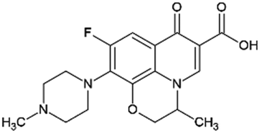
|
TGA
Thermal degradation of selected polymers was initially examined with thermogravimetric analysis (TGA) in a nitrogen atmosphere. TGA was performed with LECO TGA701, (St. Joseph, USA). The initial mass of the sample was 1 gram. The sample was placed in a ceramic crucible. The material was heated from laboratory temperature (25 °C) to 1000 °C with an applied heating rate of 5 °C min−1.The TGA instrument was also used in pyrolysis experiments. In the pyrolysis experiments, 2 g of PEEK was placed per crucible and 19 crucibles were fitted into a tray of the TGA. The material was heated from laboratory temperature (25 °C) to 600 °C with a heating rate of 10 °C min−1. The dwell time was 3 hours. The pyrolysis was performed in a nitrogen atmosphere. The crucibles were covered by lids. The pyrolysis yield of char was about 50 wt%, e.g., 20 g per pyrolysis experiment. The solid residue, i.e., char was crushed in a mortar and sieved. The experiment was repeated several times until about 50 g of the material of the correct fraction was collected. The size fraction utilized in this work was 0.16–0.315 mm.
The proximate and elemental analysis
The proximate analysis of pristine PEEK according to the ASTM D7582 standard (LECO, TGA 701, St. Joseph, USA) consisted of the moisture (wt%), volatile matter (wt%), fixed carbon (wt%) and ash content (wt%) determination.The elemental analysis according to Standard ASTM D3172-13 and D5373-16 (LECO CHNS 628, St. Joseph, USA) determined the content of elements C, H, and N. The oxygen content was calculated from data gathered in elemental and proximate analysis.
XRF
The chemical composition of the PEEK was studied using energy dispersive X-ray fluorescence spectrometer XEPOS (SPECTRO, Germany). The measurement was carried out in the air in a special cuvette supplied with a polymer film.XRD
X-Ray powder diffraction (XRD) patterns were measured using a Rigaku SmartLab diffractometer in the Bragg–Brentano geometry, using Co Kα radiation, with a D/teX Ultra 250 detector collecting the scattered intensity in the diffraction angle (2θ) range of 5–90°. The investigated sample was compared with the reference diffractogram database published by ICDD (PDF-2).SEM
A scanning electron microscope with a tungsten cathode (SEM: Tescan Vega, Brno, Czech Republic) was used for the microscopic examination of PEEK. Micrographs were obtained using a combination of secondary electrons (SE) and backscattered electrons (BSE) mode (SE + BSE) with an acceleration voltage of 15 keV. Samples before imaging were gold-sputtered (with Quorum Q150R ES plus sputter) in order to ensure adequate electron conductivity. Photographs were taken from random places on the samples to ensure an unbiased examination of the samples (without focusing on unnecessary anomalies or artifacts).FTIR
The infrared spectra were measured by the KBr technique, using the FTIR spectrometer Nicolet iS50 (Thermo Scientific, USA) with DTGS detector in transmission mode with 64 scans at a resolution of 4 cm−1 in the spectral range of 4000–400 cm−1.XPS
XPS spectra were obtained using a Phoibos 100 X-ray photoelectron spectrometer (SPECS Surface Nano Analysis GmbH, Berlin, Germany) operating in fixed analyzer transmission (FAT) mode (SPECS) with a five-channel MCD-5 detector (SPECS). An achromatic X-ray source XR50 (SPECS) was used with an Al X-ray tube and Kα line (energy of 1486.6 eV) at 12 kV, 200 W, and no flood gun was used. The powder sample was placed on a double side carbon conductive adhesive tape in a stainless-steel sample holder in a thick layer. The survey spectrum was acquired at a pass energy of 40 eV, and high-resolution spectra were acquired at a pass energy of 10 eV. The spectra were analyzed in CasaXPS, and the Shirley background model was used.Physisorption
Nitrogen physisorption at 77 K was performed using 3 flex micromeritics instruments. Prior to the nitrogen adsorption–desorption measurements, the samples were degassed at a temperature of 350 °C for 24 h under vacuum lower than 1 Pa. Carbon dioxide physisorption at 273 K was performed using the static manometric adsorption system Autosorb iQ-XR (Quantachrome Instruments) in a range of 10−5–0.03 p/p0. Prior to the isotherm measurements, the samples were degassed at a temperature of 300 °C for 24 h under vacuum lower than 1 Pa.For the evaluation of the N2/77 K adsorption isotherms, the Brunauer–Emmett–Teller (BET) theory was used to calculate the BET area marked as SBET (in m2 g−1)48,49 with respect to Rouquerol's criteria.50 The volume and surface area of the mesopores (Vmeso, Smeso) and the volume of the micropores and ultramicropores (Vmicro, Vultramicro) were calculated from the pore size distribution curve. We do not provide the surface area of the micropores with respect to the volume-filling mechanism of adsorbate in micropores.51 Therefore, only the micropore volume should be reported. The pore size distribution was obtained by fitting the nitrogen adsorption isotherm by a hybrid QSDFT adsorption kernel, assuming slit-shaped micropores and cylindrical mesopores using VersaWin software (Quantachrome Instruments). This kernel is limited to pores of diameter below 33 nm. The CO2 adsorption–desorption isotherms were obtained in order to determine the micropore volume (Vmicro). The porous properties were determined using the GCMC (grand canonical Monte Carlo) adsorption kernel, assuming slit-shaped carbon micropores.
Zeta potential and isoelectric point
The zeta potential of samples was determined using a Litesizer™ 500 (Anton Paar, Graz, Austria), with a light source of 658 nm red laser (40 mW) at 25 °C. The samples were dispersed in different media (distilled water, 0.001 M KCl, 168.7 μg L−1 of ofloxacin, or 148.5 μg L−1 for diclofenac), and then placed in an Omega cuvette (∼300 μL per sample). Data were evaluated by the accompanying software program, Kalliope™. Each sample was measured three times. Zeta potential measurements to determine the isoelectric point were performed in distilled water and KCl on a Zetasizer Nano ZS (Malvern Panalytical, UK), and processed using Zetasizer software 8.02 (Malvern Panalytical, UK). All samples were prepared at a concentration of 1 g L−1, sonicated for 5 min (35 kHz, 120 W) and their pH was adjusted as necessary using 0.1 mol L−1 HCl or NaOH. These samples were measured three times, and the value given is the average of the three measurements. The zeta potential was calculated in software by the Smoluchowski model.Adsorption experiments
Equilibrium and kinetic experiments were carried out to test the adsorption capacity of the materials. Diclofenac sodium salt and ofloxacin (Sigma Aldrich, St. Louis, MO, USA) were used for the adsorption experiments. The solutions of diclofenac sodium salt (148.5 μg L−1) and ofloxacin (168.7 μg L−1) were prepared. The concentrations of stock solutions were chosen to be mutually equimolar. The diclofenac solution was prepared by dissolving 2.97 mg of diclofenac sodium salt in 200 mL of demineralized water. A 5-mL volume of this solution was diluted with demineralized water to a final volume of 500 mL. Analogically, the ofloxacin stock solution was prepared by dissolving 3.374 mg of ofloxacin in 200 mL of demineralized water and subsequently diluting the solution to the required concentration. For kinetic measurement, 25 mL of the solution was pipetted to a 50 mL Erlenmeyer flask and mixed with 20 mg of the adsorbent. Each mixture was mixed for different time periods with the aid of a laboratory shaker (Standard Analog Shaker, Model 3500, agitation speed 150 rpm, VWR, Radnor, PA, USA). Then, the solution was filtered (Whatman, membrane filters, ME 24/12 ST, 0.2 μm).High dosages of adsorbate do not necessarily result in high adsorption efficiency, as the adsorbate may agglomerate and sterically block pore entrances. Also, the real concentrations found in the environment are usually much lower. Therefore, we decided to use the following concentrations in the kinetic test, diclofenac sodium salt c0 = 148.5 μg L−1 and ofloxacin c0 = 168.7 μg L−1.
For the construction of adsorption isotherms, the solutions of both diclofenac and ofloxacin were prepared in the initial concentration range of 1–50 mg L−1. The volume of 25 mL of each solution was pipetted to a 50 mL Erlenmeyer flask, mixed with 20 mg of prepared adsorbent, and shaken for 24 hours on a laboratory shaker.
The residual concentrations of the pharmaceuticals were determined with the aid of liquid chromatography coupled with tandem mass spectrometry (LC-MS). A Nexera X2 chromatograph (Shimadzu, Kyoto, Japan) coupled with a QTRAP 6500+ mass spectrometer (Sciex, USA) equipped with an electrospray ionization source was used for this work. The chromatographic separation of diclofenac was performed on a Kinetex Phenyl-hexyl analytical column (150 × 3 mm i.d., 2.6 μm) equipped with an adequate guard column. The mobile phase used for diclofenac separation consisted of 5 mM ammonium formate in ultrapure water (phase A) and in methanol (phase B). An analytical Kinetex XB-C18 column (150 × 4.6 mm i.d., 2.6 μm), guarded with a suitable guard column, was used for the chromatographic separation of ofloxacin along with the mobile phase consisting of acetonitrile (A) and 0.5% formic acid in ultrapure water (B). All columns were purchased from Phenomenex (Torrance, CA, USA). Both analytical methods used gradient elution with a flow rate of 0.350 mL min−1 and injection of 5 μL. The tandem mass spectrometer was operated in positive mode. For each target analyte, two MRM transitions were used (one for quantification and one for qualification). The MS operational settings were as follows: capillary voltage: 5.5 kV, capillary temperature: 450 °C, the nebulizer gas pressure: 50 psi, the heater gas pressure: 60 psi.
The models applied to interpret the equilibrium data included the following: Langmuir, Freundlich, Redlich–Peterson, and Dubinin–Radushkevich. The kinetics data were interpreted with the following equations: pseudo-first order, pseudo-second order, Elovich, and intraparticle diffusion. As will be shown later, the system with ofloxacin did not reach adsorption equilibrium after 24 h. Consequently, we are introducing a distinct parameter solely for this system q24h (mg g−1), denoting the adsorption uptake of ofloxacin after 24 hours (because the term qe cannot be used in this instance). The goodness of fit of the adsorption data with selected equations and models was determined by Radj2, which is a modified version of R2 that considers the number of independent variables.
Adsorption data interpretation
Four equations were used for the interpretation of the adsorption kinetics.The pseudo-first order model was originally proposed by Lagergren:52
| q(t) = qe(1 − e−k1t), | (1) |
The pseudo-second order model was first published by Blanchard et al.:53
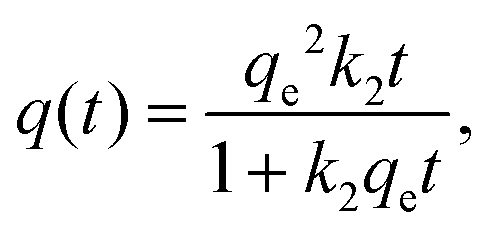 | (2) |
The Elovich model was first proposed by Roginsky and Zeldovich:54
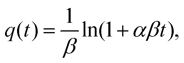 | (3) |
The intraparticle diffusion model describes the reaction pathways and adsorption mechanisms better than the three models mentioned above. It can be useful for the prediction of a controlling step as well. Its linearized form55 is described as follows:
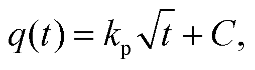 | (4) |
For the modeling of the adsorption isotherms, four models were applied.
The Langmuir equation56 was developed based on four assumptions: a fixed number of active sites with the same energy, reversible adsorption, no further adsorption on an occupied site, and no interaction between adsorbate species.
 | (5) |
The Freundlich equation57 is one of the earliest empirical equations to describe the equilibrium data and adsorption characteristics for a heterogeneous surface.
| qe = kFcne, | (6) |
The Redlich–Peterson equation58 incorporates both Langmuir and Freundlich models.
 | (7) |
The Dubinin–Radushkevich equation59 was developed to account for the effect of the porous structure of an adsorbent.
| qe = qRDe−kRDε2, | (8) |
 | (9) |
Results and discussion
Characterization of char
Selected polymer materials were studied using TG analysis to ascertain the yield of char. The polymers were selected based on their structural units containing heterocyclic and aromatic carbons and heteroatoms (oxygen). Polystyrene is a long hydrocarbon chain polymer with attached phenyl groups. Ethylene norbornene copolymer is a cyclic olefin polymer composed of norbornene, which is a highly strained bridged cyclic hydrocarbon, and ethylene a simple hydrocarbon. Polyetheretherketone is composed of aromatic rings linked by ether and ketone groups. Polycarbonate is an aromatic polymer with carbonate linkages. The char yield from TGA was 0.05 wt% for PS, 0.05 wt% for COC, 28.83 wt% for PEEK, and 0.02 wt% for PC. Based on the initial TGA data (in Fig. S1, ESI†), it was revealed that the most promising material was the PEEK polymer. Further research was therefore focused on this material. Pristine PEEK material was characterized by selected methods (proximate and elemental analysis, XRD, XRF, FTIR) before the pyrolysis experiments and other processing. The FTIR of pristine PEEK required cryogenic milling (RETSCH CryoMill) as a pretreatment. Pyrolyzed PEEK material was crushed in mortar, sieved to particle size fractions <0.16 mm and 0.16–0.315 mm, and characterized by elemental analysis, XRD, XRF, FTIR, XPS, SEM, N2 and CO2 physisorption, isoelectric point, and zeta potential in solutions of pharmaceuticals. The adsorption experiments with pharmaceuticals (diclofenac and ofloxacin) were performed with pyrolyzed PEEK (particle size fraction of 0.16–0.315 mm).TGA of the pristine PEEK material in (Fig. 1a) indicates that degradation of PEEK in the N2 atmosphere starts at 510 °C. Most of the material degrades at this temperature. In the temperature window of 510–600 °C, 37.10% of the mass content is lost. The decomposition further progresses on a smaller scale up to 760 °C. From 760 °C to 1000 °C, the material decomposes at a stable rate and the loss of mass is linear. In the temperature window of 600–760 °C, 18.71% of the mass content is lost. In the window 760–1000 °C, a further 17.22% of the mass content is lost. At 557 °C, breakdown of the ketone and ether bonds of the PEEK (structure of the PEEK polymer molecule shown in ESI,† Table S1) takes place. Further decomposition in the range of 600–800 °C is due to oxidization of the char, which is in good agreement with Gaitanelis et al.60 The crucible lid is proved to have a great effect on the char yield. The char yield in TGA without the lid was 28.83 wt% (Fig. 1a). Meanwhile, with the lid on, it was 51 wt% (Fig. 1b). The lid prevents the immediate escape of volatile organic compounds and increases their contact time with the char, thus allowing for their interaction, e.g., crosslinking and their reintegration into the polycyclic aromatic structure. The conditions in the pyrolysis experiment were based on the TGA results.
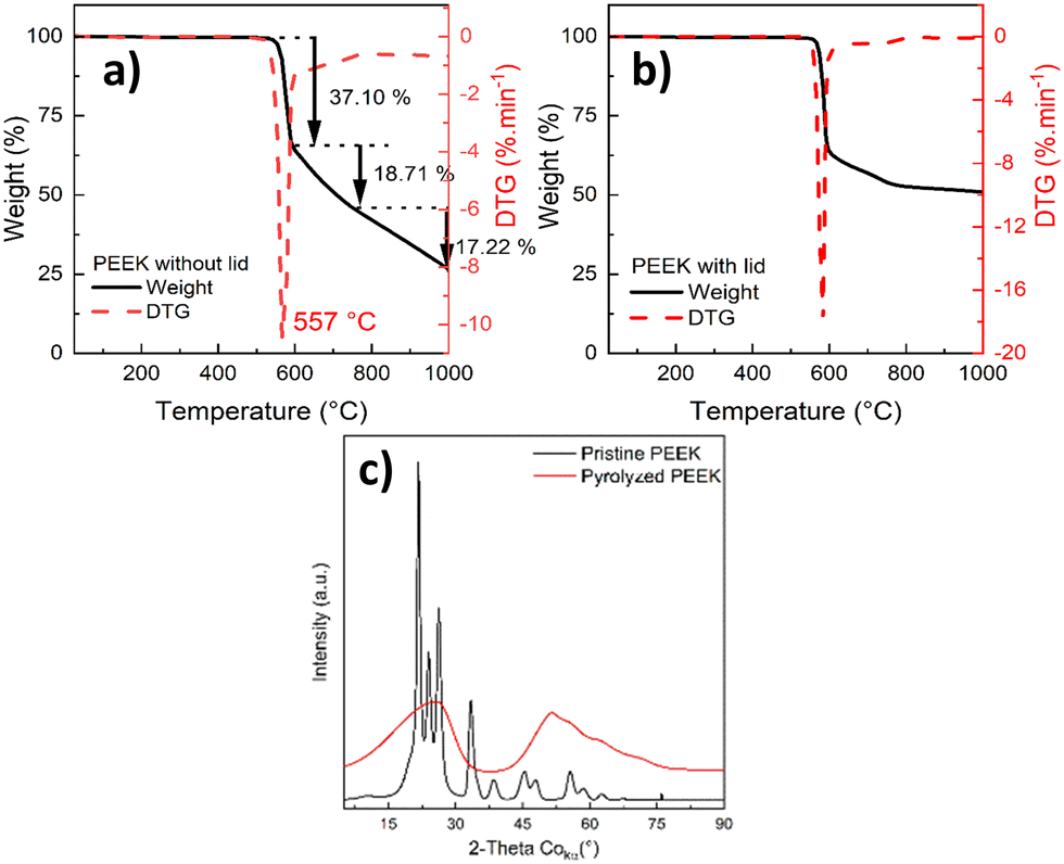 | ||
| Fig. 1 TGA of pristine PEEK with lid (a) and without lid (b), and XRD of pristine and pyrolyzed PEEK (c). | ||
The material was heated from laboratory temperature (25 °C) to 600 °C with a heating rate of 10 °C min−1. The dwell time was set to 3 hours, the crucible was covered with a lid, and the pyrolysis was performed in a nitrogen atmosphere. Such conditions are also commonly used in the pyrolysis of biomass.
The XRD analysis in Fig. 1c of the pristine PEEK shows a crystalline material. The four diffraction peaks at 2θ of 21.7°, 24.0°, 26.3°, and 33.4° correspond to the diffractions of the (110), (111), (200), and (211) crystalline planes of the orthorhombic unit cell of PEEK, respectively.61,62 The pristine PEEK diffractogram was identified as a PEEK polymer according to the reference card 00-047-1946 in the ICDD (PDF-2) database. The diffractogram of pyrolyzed PEEK shows an amorphous material. The aforementioned breakdown of the ketone and ether bonds, and the subsequent cross-linking and reorganization of the structure had an adverse effect on the ordered structure. Therefore, the crystallinity of the pyrolyzed PEEK material is very low.
The chemical composition of the pristine and pyrolyzed PEEK was determined using XRF (in Table S2, ESI†). The content of the impurities in the pristine PEEK and pyrolyzed PEEK was 0.4 wt% and 1.7 wt%, respectively. The increase seen in pyrolyzed PEEK can be explained by concentration (impurities are not volatile and do not leave during pyrolysis). The proximate and elemental analysis in Table 2 showed that the pristine PEEK consists mainly of carbon, oxygen, and hydrogen. The oxygen content in the pyrolyzed PEEK decreased significantly, but the carbon followed the opposite trend. The pyrolyzed PEEK is a char material with a very high content of carbon (95 wt%). The ash content from the proximate analysis corresponds very well with the results of the XRF analysis of the pristine PEEK.
| [wt%] | Moisture | Ash | Fixed carbon | Volatile | C | H | N | O |
|---|---|---|---|---|---|---|---|---|
| Pristine PEEK | 2.16 | 0.42 | 83.41 | 14.01 | 79.20 | 4.34 | <0.05 | 13.83 |
| Pyrolyzed PEEK | — | — | — | — | 94.95 | <0.01 | 0.18 | 2.29 |
The bulk and surface chemistry (functional groups) were studied using FTIR (Fig. 2 and Table S3, ESI†) and XPS analysis (Fig. 3), respectively.
 | ||
| Fig. 2 FTIR spectra of the pristine and pyrolyzed PEEK, pyrolyzed PEEK (top, red color), and pristine PEEK (bottom, black color). | ||
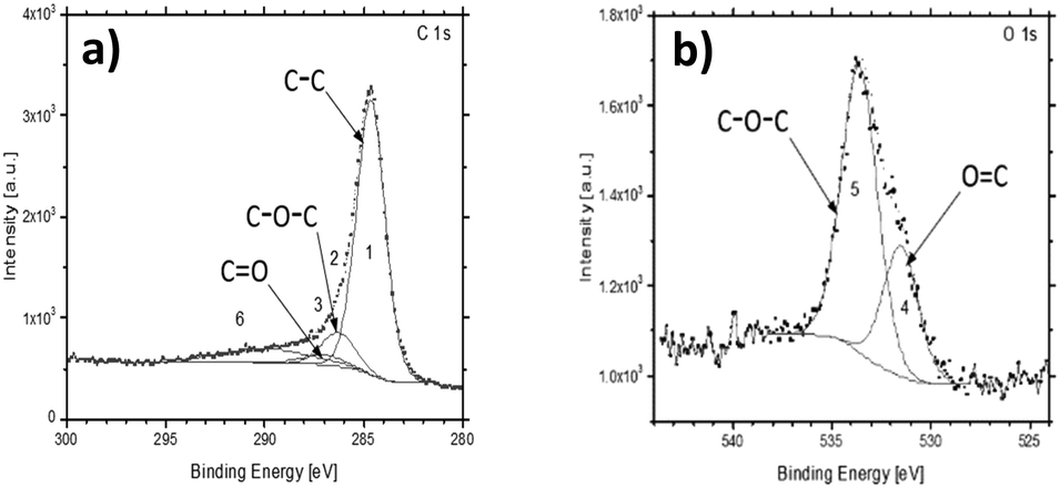 | ||
| Fig. 3 High-resolution XPS spectra of pyrolyzed PEEK C 1s (a) and O 1s (b). | ||
The chemical structure of the pristine and pyrolyzed PEEK was examined with FTIR. The FTIR spectrum of as-received pristine PEEK is shown in Fig. 2. Most of the bands in the spectrum of pristine PEEK are characteristic for the aromatic ring vibrations; only bands above 3500 cm−1 are characteristic of the stretching vibration of O–H from moisture. The bands between 3000 and 3100 cm−1 are due to the stretching vibration of C–H in the aromatic ring. The bands between 1600 and 1400 cm−1 belong to the stretching vibration of C![[double bond, length as m-dash]](https://www.rsc.org/images/entities/char_e001.gif) C in the aromatic rings. The bands between 1000 and 700 cm−1 are assigned to the out-of-plane deformation vibration of C–H in the aromatic rings (overtones of this vibration are visible between 2100 and 1800 cm−1). The bands below 700 cm−1 belong to the skeletal deformation vibration of the aromatic rings. The functional groups are represented by bands at 1230 cm−1 and at ca. 1180 cm−1; both mentioned bands are due to the asymmetric stretching vibration of C–O–C in the aromatic ethers. The band at ca. 1780 cm−1 is characteristic of the stretching vibration of CO of aromatic aldehydes (at the end of the polymer chain of pristine PEEK). The band at ca. 1660 cm−1 belongs to the stretching vibration of CO of the aromatic ketones (the overtone of this vibration is at ca. 3300 cm−1 in the spectrum). The presence of an aromatic aldehyde band is confirmed by the presence of bands of Fermi resonance between 2900 and 2650 cm−1. In the spectrum of pyrolyzed PEEK, the spectral bands of aromatic ring are also present as follows: 3047 cm−1 (stretching vibration of C–H in aromatic compounds); ca. 1585 cm−1 (stretching vibration of CC); bands below 900 cm−1 (out-of-plane deformation vibration of C–H). The bands at 2910 cm−1 and 2850 cm−1 belong to the stretching vibration of C–H in aliphatic hydrocarbons (CH2 groups). The band at ca. 1700 cm−1 belongs to the stretching vibration of CO probably in ketones. Bands at ca. 1170 cm−1 are due to the stretching vibration of C–O–C in ethers. For the list of FTIR bands, please see Table S3 (ESI†). The above assignment of the spectral bands (in the spectra of both samples) was made according to monography by M. Horák.63
C in the aromatic rings. The bands between 1000 and 700 cm−1 are assigned to the out-of-plane deformation vibration of C–H in the aromatic rings (overtones of this vibration are visible between 2100 and 1800 cm−1). The bands below 700 cm−1 belong to the skeletal deformation vibration of the aromatic rings. The functional groups are represented by bands at 1230 cm−1 and at ca. 1180 cm−1; both mentioned bands are due to the asymmetric stretching vibration of C–O–C in the aromatic ethers. The band at ca. 1780 cm−1 is characteristic of the stretching vibration of CO of aromatic aldehydes (at the end of the polymer chain of pristine PEEK). The band at ca. 1660 cm−1 belongs to the stretching vibration of CO of the aromatic ketones (the overtone of this vibration is at ca. 3300 cm−1 in the spectrum). The presence of an aromatic aldehyde band is confirmed by the presence of bands of Fermi resonance between 2900 and 2650 cm−1. In the spectrum of pyrolyzed PEEK, the spectral bands of aromatic ring are also present as follows: 3047 cm−1 (stretching vibration of C–H in aromatic compounds); ca. 1585 cm−1 (stretching vibration of CC); bands below 900 cm−1 (out-of-plane deformation vibration of C–H). The bands at 2910 cm−1 and 2850 cm−1 belong to the stretching vibration of C–H in aliphatic hydrocarbons (CH2 groups). The band at ca. 1700 cm−1 belongs to the stretching vibration of CO probably in ketones. Bands at ca. 1170 cm−1 are due to the stretching vibration of C–O–C in ethers. For the list of FTIR bands, please see Table S3 (ESI†). The above assignment of the spectral bands (in the spectra of both samples) was made according to monography by M. Horák.63
The survey XPS spectra of the pyrolyzed PEEK sample identified the presence of expected carbon C 1s, oxygen O 1s, and Auger O KLL peaks at expected binding energies (BE) (Fig. S2, ESI†). The shapes of the high-resolution spectra of C 1s and O 1s are very close to the reference PEEK polymer data64 (Fig. 3). The increased full width half maximum (FWHM) of our data corresponds to the powder character of the sample and the used achromatic X-ray source. The achromatic X-ray source was used to simplify the measurement. The carbon-related C 1s peak can be fitted by 3 main components at BE 284.7 eV, 286.31 eV, and 287.10 eV labeled from 1 to 3, respectively. The binding energies correspond to the elemental constituents of PEEK, where 1 is C–C, 2 is C–O–C, and 3 is CO.64 The last component of the C 1s peak in the literature is around 291.59 eV, where our data show a significantly wider peak or more probably a set of multiple peaks. These correspond to various functional groups as observed on FTIR, and it was labeled as 6. The XPS is not able to distinguish them, but only confirms their presence (component number 6). The O 1s peak of the PEEK sample is also in agreement with the reference PEEK data, where two main components are present. They are labeled as 4 for OC at 531.5 eV and 5 for the C–O–C parts of PEEK at 533.59 eV. The higher energy part of the spectra shows a bump in the background. It is most probably caused by the abovementioned functional groups observed also in the C 1s spectra as the broader component labeled 6.
The FTIR and XPS results are in good agreement with the literature on the surface analysis of the pyrolyzed lignocellulosic biomass.65 Both methods confirm the presence of oxygen functional groups. No other functional groups containing a heteroatom were detected. The advantage of the polymer pyrolysis feedstock over the chemical composition of the product is well demonstrated here. The char/adsorbent possesses only oxygen functional groups. Although the surface chemistry of the material is still complicated, the contribution of other heteroatoms can be discarded. This feature can be helpful in the research of precise adsorption mechanisms, a task that would be too complex to perform with biomass-based adsorbents.
The morphology of the pyrolyzed PEEK (char crushed in mortar and sieved) was studied with SEM (Fig. 4). Particles look very homogeneous and appear to be chipped from a larger block. The shape of the individual particles resembles glass shards or obsidian. The particles have long, sharp edges and a conchoidal fracture (Fig. 4a and b). The surface of the particles is smooth, but a closer look shows the presence of a small number of round macropores. The homogeneous nature of the material stems from the fact that the starting material is a chemically pure substance that is first melted in a pyrolysis experiment, and then the molten substance is pyrolyzed. The resulting char resembles a stiff meringue-like foam.
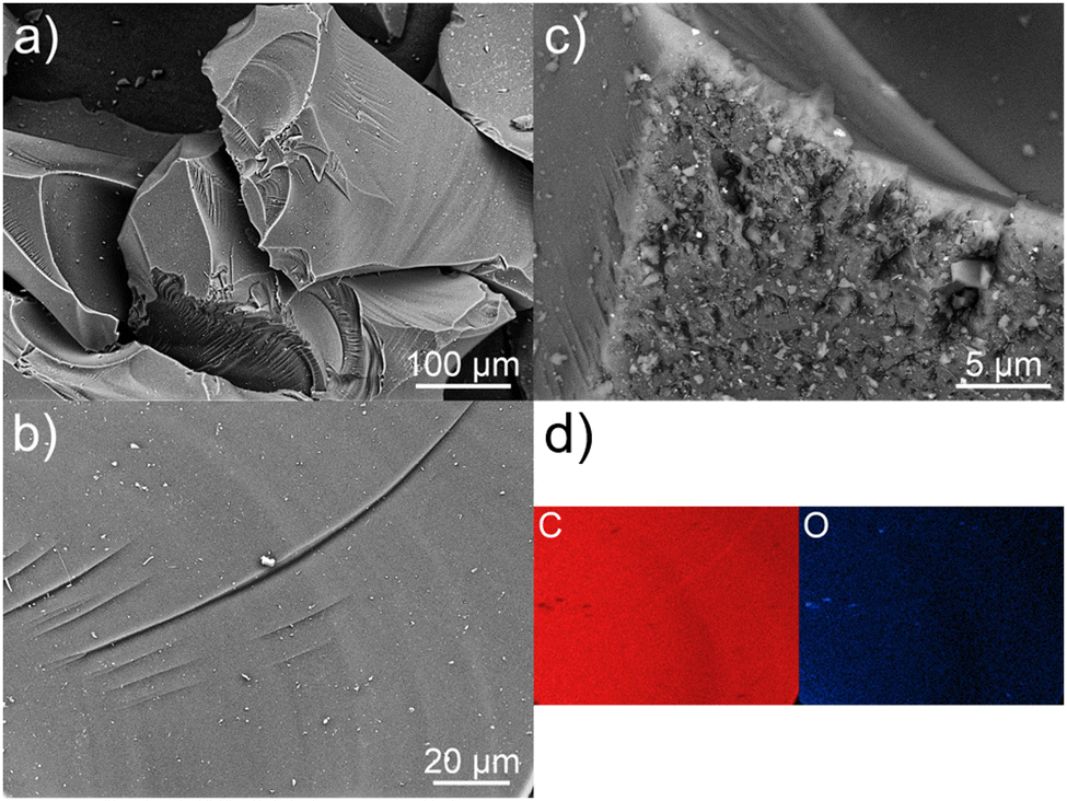 | ||
| Fig. 4 SEM image of the PEEK morphology (a)–(c); chemical map of the carbon and oxygen distribution on the surface (d). | ||
The BET area, and microporous and mesoporous characteristics (including pore size distribution) were studied with N2 and CO2 physisorption. The N2 adsorption–desorption isotherm for pyrolyzed PEEK 0.16–0.315 mm is shown in Fig. 5a. The isotherm is of type I(b) according to IUPAC classification,66 which is found with materials having pore size distributions over a broader range including wider micropores (pores smaller than 2 nm) and possibly narrow mesopores (≲2.5 nm). The isotherm has an unclosed hysteresis, which is sometimes found in carbonaceous materials with slit-like micropores.66–69 From the isotherm and Table 3, it is apparent that the material is predominantly microporous (0.198 cm3 g−1) with a small number of mesopores (0.027 cm3 g−1) ranging between 10–30 nm (inset of Fig. 5c). Although the QSDFT kernel used to calculate the pore size distribution is limited to pores smaller than about 33 nm, the nature of the N2 adsorption isotherm (Fig. 5a) does not suggest the substantial presence of larger mesopores. The micropore size distribution calculated from the N2 adsorption isotherm (Fig. 5c) refers to the presence of fewer supermicropores (0.7–2 nm) and a large volume of ultramicropores (pore width <0.7 nm) with the most frequent width (modus) at 0.55 nm. The values from Table 3 are comparable with those reported in the literature, e.g., pyrolyzed coconut fibres.70 The micropore volume calculated from the CO2 adsorption isotherm for the PEEK sample (Fig. 5a) is in reasonable agreement with nitrogen physisorption results (Table 3), and exactly confirms 0.55 nm as the modal micropore width (Fig. 5b).
 | ||
| Fig. 5 N2 physisorption at 77 K (red color) and CO2 physisorption at 273 K (black color) on pyrolyzed PEEK (a); micropore distribution (b) and mesopore distribution (N2/77 K) (c). | ||
| Method | S BET (m2 g−1) | S meso (m2 g−1) | V meso (cm3 g−1) | V micro (cm3 g−1) | V ultramicro (cm3 g−1) |
|---|---|---|---|---|---|
| S BET = BET area. Vmeso and Smeso = mesopore volume and surface area, respectively. Vmicro = micropore volume. Vultramicro = volume of ultramicropores. | |||||
| N2/77 K physisorption | 579.4 | 40.3 | 0.027 | 0.198 | 0.062 |
| CO2/273 K physisorption | — | — | — | 0.187 | 0.135 |
It is worth noting that the adsorption and desorption of CO2 are reversible, as only a negligible hysteresis appears compared to the N2 physisorption result. Such “open” or “low-pressure” hysteresis that does not close below 0.42 p/p0 (for N2/77 K) has already been described in the literature (e.g., in ref. 66–69). It is usually attributed to, e.g., diffusion-controlled hysteresis due to the restricted diffusion of adsorptive molecules into (during the adsorption) or out (during the desorption) of the narrow micropores. Another explanation may lie in a pore deformation due to the swelling and contraction of the pore system during adsorption or desorption. By comparing the volume of ultramicropores (Vultramicro in Table 3) calculated from N2 and CO2 isotherms, it is clear that CO2 gives an ultramicropore volume that is more than double the value of the one from N2. This can be attributed to the well-known restricted diffusion of N2 molecules into/out of the narrow (ultra)microporosity71 of the PEEK material under the cryogenic measurement temperature (77 K). This hypothesis gains support from the pore size distributions (Fig. 5b) calculated from both CO2 and N2 adsorption experiments, revealing that the PEEK sample predominantly contains small ultramicropores with a size of 0.55 nm. We therefore speculate that the diffusion-controlled hysteresis may explain the low-pressure hysteresis found during N2 sorption in such small ultramicropores.
Sorption kinetics and equilibrium tests
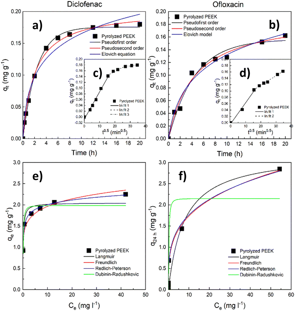 | ||
| Fig. 6 Sorption tests with pyrolyzed PEEK. Kinetic data (a) and (b) with the intraparticle diffusion model in the inlay (c) and (d); adsorption isotherms (25 °C) (e) and (f). | ||
The course of adsorption differs between both contaminants based on intraparticle diffusion curves. From the intraparticle diffusion model (Fig. 6c, d and Table S4, ESI†), it is apparent that there is the presence of multiple linear regions. In the case of diclofenac removal, there are three linear regions corresponding to three individual steps of the adsorption process (film diffusion, intraparticle diffusion, and adsorptive attachment). Conversely, in the case of ofloxacin, we noticed only the first two of the mentioned steps. The intraparticle diffusion is therefore not the sole mechanism of adsorption, and the adsorption process consists of multiple mechanisms.
When compared with the literature, the obtained maximum adsorption capacities qe appear notably low (Tables S9 and S10, ESI†). Therefore, we endeavored to identify the underlying cause by evaluating the size of the adsorbate (diclofenac and ofloxacin) molecules related to the modal (most frequent) size of micropores in the PEEK material. To determine the size of these molecules, we relied on data sourced from the Crystallography Open Database.72–74 The estimated dimensions of the diclofenac molecule were found to be approximately 0.93 nm in length and 0.74 nm in width, while the ofloxacin molecule measured approximately 1.32 nm in length and 0.74 nm in width. It becomes evident that the widths of both molecules exceed the modal micropore size of PEEK, which stands at 0.55 nm (Fig. 5b). It can be deduced from Table 3 that the volume of the ultramicropores (corresponding well with the widths of the adsorbate molecules) account for over 70% of the total micropore volume (calculated from the CO2 adsorption data). This observation indicates that steric hindrance at the ultramicropores can be responsible for the inaccessibility of active sites in ultramicropores by diclofenac and ofloxacin molecules, and consequently their weak adsorption uptake.
In addition to steric limitations, the adsorbent-adsorptive interactions also may play a significant role. To investigate this, we performed zeta-potential measurements on a PEEK sample suspended in water, diclofenac, ofloxacin, and KCl solutions. The zeta potentials are shown in Table S5 (ESI†). The suspensions of the pharmaceuticals were diluted so much that the differences in zeta potentials were negligible when compared to distilled water (ζ = −28.1 mV). The isoelectric point (IEP) for suspensions defines the pH at which the net electrical charge on the surface of the dispersed particles is equal to zero. The pH measurements revealed that the isoelectric point of the PEEK (Fig. S3a and b, ESI†) was approximately 2.4 in H2O and 3 in KCl. The equilibrium pH values after all of the adsorption experiments in this study were approximately 6.8 (initial pH = 8.1) for diclofenac and 6.4 (initial pH = 7.6) for ofloxacin. Since these equilibrium pH values for both pharmaceuticals far exceed their pHIEP values, it can be assumed that the overall surface charge of the adsorbent was negative under the sorption experiments, which may make the PEEK adsorbent suitable for the adsorption of cations.
To find out if the molecules of pharmaceuticals are dissociated under the pH of adsorption experiments, the pKa values are taken into account. The pKa values for diclofenac (pKa = 4.15) and ofloxacin (pKa1 = 5.97 for the carboxylic acid group and pKa2 = 8.28 for the piperazinyl ring nitrogen) show that both pharmaceuticals are in dissociated and partially dissociated form in their respective solutions.75 Dissociated pharmaceuticals are ionized (in the form of anions). Therefore, based on the data from IEP (zeta potential measurement) and pKa values, it can be surmised that at the experimental pH (during the adsorption experiments), both pharmaceutical solutions and the adsorbent are negatively charged, which negatively influences the adsorption uptake.
In summary, the novel PEEK material adsorbs pharmaceutical substances like diclofenac and ofloxacin. However, its ultramicroporous nature is not sufficiently exploited due to the large size of the pharmaceutical molecules that can only partially penetrate the micropores. At the same time, there are the repulsive forces between the adsorbent and molecules of the pharmaceuticals. The PEEK material therefore appears to be better suited as a sorbent for small molecules or heavy metal cations.
Conclusion
A carbonaceous adsorbent was created through the pyrolysis of a polyetheretherketone (PEEK) polymer. The resultant carbon material possesses a microporous structure with a large surface area and narrow pore distribution, with a modal pore size of 0.55 nm. The surface analysis confirmed the presence of oxygen functional groups, such as ethers, aldehydes, and ketones. In the adsorption tests, diclofenac and ofloxacin were used as model adsorbates. The results of the kinetic and equilibrium adsorption tests were interpreted using selected models. The material is better suited for adsorbing smaller positively charged pollutants, as indicated by the adsorption tests and characterization. Activation or functionalization could further improve the textural and adsorption properties of this material. The successful demonstration of the potential of polymers in creating carbonaceous adsorbents was achieved. The distinct properties of polymers enable the creation of tailor-made adsorbents suitable for investigating adsorption mechanisms.Author contributions
J. Lang: conceptualization, formal analysis, visualization, writing – original draft, writing – review & editing. J. Bednárek: investigation, writing – original draft. M. Ritz: investigation, writing – review & editing. M. Kormunda: investigation, writing – review & editing. T. Zelenka: investigation, writing – review & editing. M. Vaštyl: conceptualization, writing – review & editing. A. Gavlová: investigation, writing – review & editing, visualization. Z. Kolská: investigation, writing – review & editing. M. Férová: investigation, writing – review & editing.Data availability
The data that support the findings of this study are available on request from the corresponding author, Jaroslav Lang.Conflicts of interest
The authors declare that they have no known competing financial interests or personal relationships that could have appeared to influence the work reported in this paper.Acknowledgements
The authors would like to thank the Large Research Infrastructure ENREGAT supported by the Ministry of Education, Youth and Sports of the Czech Republic under project No. LM2023056. This work was financially supported by the European Union under the REFRESH - Research Excellence For REgion Sustainability and High-tech Industries project No. CZ.10.03.01/00/22_003/0000048 via the Operational Programme Just Transition. Special thanks to Ing. Hynek Beneš, PhD for his advice regarding the selection of an initial set of polymers, Mgr. Daniel Cvejn, PhD for consultation, and Prof. Ing. Kamila Kočí, PhD for her support.References
- T. H. Miller, K. T. Ng, S. T. Bury, S. E. Bury, N. R. Bury and L. P. Barron, Environ. Int., 2019, 129, 595–606 CrossRef CAS PubMed.
- D. Mondal, R. Periche, B. Tineo, L. A. Bermejo, M. M. Rahman, A. B. Siddique, M. A. Rahman, J. L. Solis and G. J. F. Cruz, Chemosphere, 2019, 125070, DOI:10.1016/j.chemosphere.2019.125070.
- B. G. Marshall, M. M. Veiga, R. J. Kaplan, R. Adler Miserendino, G. Schudel, B. A. Bergquist, J. R. D. Guimaraes, L. G. S. Sobral and C. Gonzalez-Mueller, Environ. Sci.: Processes Impacts, 2018, 20, 632–641 RSC.
- V. Geissen, H. Mol, E. Klumpp, G. Umlauf, M. Nadal, M. van der Ploeg, S. E. A. T. M. van de Zee and C. J. Ritsema, Int. Soil Water Conserv. Res., 2015, 3, 57–65 CrossRef.
- T. Do Minh, J. Song, A. Deb, L. Cha, V. Srivastava and M. Sillanpää, Chem. Eng. J., 2020, 124856, DOI:10.1016/j.cej.2020.124856.
- M. A. Taggart, R. Cuthbert, D. Das, C. Sashikumar, D. J. Pain, R. E. Green, Y. Feltrer, S. Shultz, A. A. Cunningham and A. A. Meharg, Environ. Pollut., 2007, 147, 60–65 CrossRef CAS.
- J. O. Ighalo and A. G. Adeniyi, ChemBioEng Rev., 2020, 7, 50–64 CrossRef CAS.
- B. R. Esposito, M. L. Capobianco, A. Martelli, M. L. Navacchia, L. Pretali, M. Saracino, A. Zanelli and S. S. Emmi, Radiat. Phys. Chem., 2017, 141, 118–124 CrossRef CAS.
- J. Georgin, D. S. P. Franco, C. G. Ramos, D. G. A. Piccilli, E. C. Lima and F. Sher, Chem. Eng. Res. Des., 2023, 193, 99–120 CrossRef CAS.
- D. G. Larsson, C. de Pedro and N. Paxeus, J. Hazard. Mater., 2007, 148, 751–755 CrossRef CAS.
- J. A. A. de Carvalho Filho, H. M. da Cruz, B. S. Fernandes, F. Motteran, A. L. R. de Paiva and J. Pereira Cabral, Environ. Pollut., 2022, 300, 118916 CrossRef CAS.
- J. Kapelewska, U. Kotowska, J. Karpińska, D. Kowalczuk, A. Arciszewska and A. Świrydo, Microchem. J., 2018, 137, 292–301 CrossRef CAS.
- M. Coha, G. Farinelli, A. Tiraferri, M. Minella and D. Vione, Chem. Eng. J., 2021, 414, 128668 CrossRef CAS.
- E. R. Cornelissen, D. J. H. Harmsen, B. Blankert, L. P. Wessels and W. G. J. van der Meer, Desalination, 2021, 509, 115056 CrossRef CAS.
- H. Abu Hasan, M. H. Muhammad and N. I. Ismail, J. Water Process Eng., 2020, 33, 101035 CrossRef.
- G. T. H. Ooi, K. Tang, R. K. Chhetri, K. M. S. Kaarsholm, K. Sundmark, C. Kragelund, K. Litty, A. Christensen, S. Lindholst, C. Sund, M. Christensson, K. Bester and H. R. Andersen, Bioresour. Technol., 2018, 267, 677–687 CrossRef CAS.
- L. Pérez-Bou, A. Rosa-Masegosa, R. Vilchez-Vargas, A. Link, A. Gonzalez-Martinez, J. Gonzalez-Lopez and B. Muñoz-Palazon, J. Water Process Eng., 2024, 60, 105206 CrossRef.
- J. H. Qu, J. Environ. Sci., 2008, 20, 1–13 CrossRef CAS.
- I. Kozyatnyk, D. M. M. Yacout, J. Van Caneghem and S. Jansson, Bioresour. Technol., 2020, 302, 122866 CrossRef CAS.
- J. Akhtar, N. A. S. Amin and K. Shahzad, Desalin. Water Treat., 2016, 57, 12842–12860 CrossRef CAS.
- M. A. Yahya, Z. Al-Qodah and C. W. Z. Ngah, Renewable Sustainable Energy Rev., 2015, 46, 218–235 CrossRef CAS.
- M. Lewoyehu, J. Anal. Appl. Pyrolysis, 2021, 159, 105279 CrossRef CAS.
- J. Lang, L. Matejova, A. K. Cuentas-Gallegos, D. R. Lobato-Peralta, K. Ainassaari, M. M. Gomez, J. L. Solis, D. Mondal, R. L. Keiski and G. J. F. Cruz, J. Environ. Chem. Eng., 2021, 9, 105979 CrossRef CAS.
- L. Matejova, J. Bednarek, J. Tokarsky, I. Koutnik, B. Sokolova and G. J. F. Cruz, Appl. Surf. Sci., 2022, 605, 154607 CrossRef CAS.
- J. Bednarek, L. Matejova, Z. Jankovska, M. Vastyl, B. Sokolova, P. Peikertova, P. Siler, A. Verner, J. Tokarsky, I. Koutnik, M. Svab and M. Vrablova, J. Environ. Chem. Eng., 2022, 10, 108003 CrossRef CAS.
- A. U. Rajapaksha, M. Vithanage, M. Ahmad, D. C. Seo, J. S. Cho, S. E. Lee, S. S. Lee and Y. S. Ok, J. Hazard. Mater., 2015, 290, 43–50 CrossRef CAS PubMed.
- J. K. H. Faltynowicz and M. Kulazynski, Open Chem., 2015, 13, 1150–1156 Search PubMed.
- I. Koutnik, M. Vrablova and J. Bednarek, Bioresour. Technol., 2020, 309, 123315 CrossRef CAS PubMed.
- Y. Dai, N. Zhang, C. Xing, Q. Cui and Q. Sun, Chemosphere, 2019, 223, 12–27 CrossRef CAS.
- J. Liu, J. Jiang, Y. Meng, A. Aihemaiti, Y. Xu, H. Xiang, Y. Gao and X. Chen, J. Hazard. Mater., 2020, 388, 122026 CrossRef CAS.
- F. R. Oliveira, A. K. Patel, D. P. Jaisi, S. Adhikari, H. Lu and S. K. Khanal, Bioresour. Technol., 2017, 246, 110–122 CrossRef CAS PubMed.
- Z. Zhang, Z. Zhu, B. Shen and L. Liu, Energy, 2019, 171, 581–598 CrossRef CAS.
- P. M. Godwin, Y. Pan, H. Xiao and M. T. Afzal, J. Bioresour. Bioprod., 2019, 4, 31–42 CrossRef.
- D. Wei, B. Li, H. Huang, L. Luo, J. Zhang, Y. Yang, J. Guo, L. Tang, G. Zeng and Y. Zhou, Chemosphere, 2018, 197, 165–180 CrossRef CAS.
- P. R. Yaashikaa, P. Senthil Kumar, S. J. Varjani and A. Saravanan, Bioresour. Technol., 2019, 292, 122030 CrossRef CAS.
- K. Laszlo, A. Bota and L. G. Nagy, Carbon, 2000, 38, 1965–1976 CrossRef CAS.
- A. Singh and D. Lal, J. Appl. Polym. Sci., 2010, 115, 2409–2415 CrossRef CAS.
- S. Ronka, J. Anal. Appl. Pyrolysis, 2014, 110, 390–400 CrossRef CAS.
- T.-H. Le and H. Yoon, Carbon, 2019, 152, 796–817 CrossRef CAS.
- M. F. Hassan, M. A. Sabri, H. Fazal, A. Hafeez, N. Shezad and M. Hussain, J. Anal. Appl. Pyrolysis, 2020, 145, 104715 CrossRef CAS.
- F. Lian, C. Chang, Y. Du, L. Zhu, B. Xing and C. Liu, J. Environ. Sci., 2012, 24, 1549–1558 CrossRef CAS PubMed.
- A. B. Al-Odayni, F. S. Alsubaie and W. S. Saeed, Polymers, 2023, 15, 806 CrossRef CAS PubMed.
- P. B. Trinh and A. I. Schafer, J. Hazard. Mater., 2023, 454, 131211 CrossRef CAS PubMed.
- M. Tagliavini, F. Engel, P. G. Weidler, T. Scherer and A. I. Schafer, J. Hazard. Mater., 2017, 337, 126–137 CrossRef CAS.
- L. Miao, X. Qian, D. Zhu, T. Chen, G. Ping, Y. Lv, W. Xiong, Y. Liu, L. Gan and M. Liu, Chin. Chem. Lett., 2019, 30, 1445–1449 CrossRef CAS.
- A. R. McLauchlin, O. R. Ghita and L. Savage, J. Mater. Process. Technol., 2014, 214, 75–80 CrossRef CAS.
- L. O. Dandy, G. Oliveux, J. Wood, M. J. Jenkins and G. A. Leeke, Polym. Degrad. Stab., 2015, 112, 52–62 CrossRef CAS.
- S. J. Gregg and K. S. W. Sing, Adsorption, Surface Area and Porosity, Academic Press, New York, 2nd edn, 1982 Search PubMed.
- S. Brunauer, P. H. Emmett and E. Teller, J. Am. Chem. Soc., 1938, 60, 309–319 CrossRef CAS.
- J. Rouquerol, P. Llewellyn and F. Rouquerol, Studies in Surface Science and Catalysis, Elsevier Inc., 2007, vol. 160, pp. 49–56 Search PubMed.
- S. Lowell, J. E. Shields, M. A. Thomas and M. Thommes, Characterization of Porous Solids and Powders: Surface Area, Pore Size and Density, Springer Netherlands, Dordrecht, Netherlands, 2004 Search PubMed.
- S. Lagergren, K. Sven. Vetenskapsakad. Handl., 1898, 24, 1–39 Search PubMed.
- G. Blanchard, M. Maunaye and G. Martin, Water Res., 1984, 18, 1501–1507 CrossRef CAS.
- Y. B. Z. S. Roginsky, Acta Physicochim. URSS, 1934, 1, 554 Search PubMed.
- W. J. Weber and J. C. Morris, J. Sanit. Eng. Div., 1963, 89, 31–60 CrossRef.
- I. Langmuir, J. Am. Chem. Soc., 1918, 40, 1361–1403 CrossRef CAS.
- H. Freundlich, Z. Phys. Chem., 1906, 57, 385–471 CAS.
- O. Redlich and D. L. Peterson, J. Phys. Chem., 1959, 63, 1024 CrossRef CAS.
- M. Dubinin and L. Radushkevich, Chem. Zentralbl., 1947, 1, 875 Search PubMed.
- D. Gaitanelis, C. Worrall and M. Kazilas, Polym. Degrad. Stab., 2022, 204, 110096 CrossRef CAS.
- M. Naffakh, M. A. Gomez, G. Ellis and C. Marco, Polym. Int., 2003, 52, 1876–1886 CrossRef CAS.
- A. M. Diez-Pascual, G. Martinez and M. A. Gomez, Macromolecules, 2009, 42, 6885–6892 CrossRef CAS.
- M. Horák and D. Papoušek, Infrared Spectra and Structure of Molecules, Academia, Prague, Czech Republic, 1976 Search PubMed.
- P. Louette, F. Bodino and J.-J. Pireaux, Surf. Sci. Spectra, 2007, 12, 149–153 CrossRef.
- J. Grams, J. Anal. Appl. Pyrolysis, 2022, 161, 105429 CrossRef CAS.
- M. Thommes, K. Kaneko, A. V. Neimark, J. P. Olivier, F. Rodriguez-Reinoso, J. Rouquerol and K. S. W. Sing, Pure Appl. Chem., 2015, 87, 1051–1069 CrossRef CAS.
- K. Lászlo, A. Bóta and L. G. Nagy, Carbon, 2000, 38, 1965–1976 CrossRef.
- P. Maziarka, C. Wurzer, P. J. Arauzo, A. Dieguez-Alonso, O. Mašek and F. Ronsse, Chem. Eng. J., 2021, 418, 129234 CrossRef CAS.
- P. I. Ravikovitch and A. V. Neimark, Adsorption, 2005, 11, 265–270 CrossRef.
- N. H. Phan, S. Rio, C. Faur, L. L. Coq, P. L. Cloirec and T. H. Nguyen, Carbon, 2006, 44, 2569–2577 CrossRef CAS.
- T. Zelenka, T. Horikawa and D. D. Do, Adv. Colloid Interface Sci., 2023, 311, 102831 CrossRef CAS.
- S. Grazulis, D. Chateigner, R. T. Downs, A. T. Yokochi, M. Quiros, L. Lutterotti, E. Manakova, J. Butkus, P. Moeck and A. Le Bail, J. Appl. Crystallogr., 2009, 42, 726–729 CrossRef CAS.
- S. Mahapatra, K. N. Venugopala and T. N. G. Row, Cryst. Growth Des., 2010, 10, 1866–1870 CrossRef CAS.
- A. Llinàs, J. C. Burley, K. J. Box, R. C. Glen and J. M. Goodman, J. Med. Chem., 2007, 50, 979–983 CrossRef.
- PubChem Compound Summary for CID 4583, Ofloxacin, https://pubchem.ncbi.nlm.nih.gov/compound/Ofloxacin.
Footnote |
| † Electronic supplementary information (ESI) available. See DOI: https://doi.org/10.1039/d4ma00141a |
| This journal is © The Royal Society of Chemistry 2024 |