
 Open Access Article
 This Open Access Article is licensed under a
 Creative Commons Attribution 3.0 Unported Licence
Structure and molecular mobility of phosphinine-based covalent organic frameworks – glass transition of amorphous COFs†
Farnaz
Emamverdi
a,
Jieyang
Huang
 b,
Paulina
Szymoniak
a,
Michael J.
Bojdys
b,
Martin
Böhning
a and
Andreas
Schönhals
*a
b,
Paulina
Szymoniak
a,
Michael J.
Bojdys
b,
Martin
Böhning
a and
Andreas
Schönhals
*a
aBundesanstalt für Materialforschung und -prüfung (BAM), Unter den Eichen 87, Berlin 12205, Germany. E-mail: Andreas.Schoenhals@bam.de; Fax: +49 30/8104-73384; Tel: +49 30/8104-3384
bDepartment of Chemistry, Humboldt University, Brook-Taylor Straße 2, Berlin 12489, Germany
First published on 2nd February 2024
Abstract
Two-dimensional covalent organic frameworks (COFs) based on phosphinine and thiophene building blocks have been synthesized with two different side groups. The materials are denoted as CPSF-MeO and CPSF-EtO where CxxF correspond to the covalent framework, whereas P and S are related to heteroatoms phosphorous and sulfur. MeO and EtO indicate the substituents, i.e. methoxy and ethoxy. Their morphologies were studied by scanning electron microcopy and X-ray scattering. The absence of crystalline reflexes in the X-ray pattern reveal that both materials are amorphous and can be considered as glasses. Furthermore, N2 adsorption measurements indicate substantial Brunauer–Emmett–Teller (BET) surface area values pointing to the formation of three-dimensional pores by stacking of the aromatic 2D layer. An analysis of the porosity of both COFs showed a mean radius of the pores to be of ca. 4 nm, consistent with their chemical structure. The COFs form nanoparticles with a radius of around 100 nm. The thermal behavior of the COFs was further investigated by fast scanning calorimetry. These investigations showed that both COFs undergo a glass transition. The glass transition temperature of CPSF-EtO is found to be ca. 100 K higher than that for CPSF-MeO. This large difference in the glass transition is discussed to be due to a change in the interaction of the COF sheets induced by the longer ethoxy group. It might be assumed that for CPSF-EtO more individual COF sheets assemble to larger stacks than for CPSF-MeO. This agrees with the much larger surface area value found for CPSF-EtO compared to CPSF-MeO. To corroborate the results obtained be fast scanning calorimetry dielectric measurements were conducted which confirm the occurrence of a dynamic glass transition. The estimated temperature dependence of the relaxation rates of the dielectric relaxation and their absolute values agrees well with the data obtained by fast scanning calorimetry. Considering the fragility approach to the glass transition, it was further found that CPSF-MeO is a fragile glass former whereas CPSF-EtO behaves as a strong glass forming material. This difference in the fragility points also to distinct differences in the interaction between the 2D COF molecules in both materials.
Introduction
Covalent organic frameworks (COFs) are a novel and innovative category of materials.1,2 They are composed mainly of light elements like hydrogen, carbon, nitrogen, and oxygen etc. Depending on the building blocks two- or three-dimensional frameworks are formed by the reaction between organic precursors molecules which results in strong covalent bonds. In case of aromatic 2D structures the obtained sheets can form larger structures linked by π–π interactions. Thus, stable nonporous3,4 as well as microporous5 frameworks are obtained with can be either crystalline or amorphous. These nano- or mesopores may form by stacking assembly of macrocyclic moieties in aromatic 2D layers.COFs can have a variety of potential applications, where one of its most prominent field is gas separation and storage, especially for hydrogen, carbon dioxide, methane as well as amonia.1 Such applications will have a high implication in the protection of our environment from the pollution by greenhouse gases or by the use of COFs in green automotive industry. When photoelectric moieties are incorporated in the well-defined framework structure, functional COFs can be obtained which possess unique electrical and optical properties.1 This direction in the application of COFs was pioneered by Jing et al. by considering pyrene-functionalized COF materials.6 Depending on the nature of the photoelectric group, COFs with different properties like luminescence, semi-conductivity or photo-conductivity can be obtained including also photon harvesting COFs. Similar to other porous materials like metal organic frameworks (MOFs) or zeolites, functional COF materials might also have a great potential in catalysis including electrochemical applications.1 This concerns mainly heterogeneous catalysis which requires materials with a high thermal stability, a resistance against water as well as most of organic solvents. In addition, easily accessible stable catalytic sides combined with an efficient mass transport in the porous network is a further requirement.
Earlier synthesized COF materials connected by boronate esters, boroxins7–10 and imines11 suffered from a poor thermal stability which limits their use in sensing and electrochemical applications. Recently, stable, and crystalline triazine-based graphdiyene frameworks that exhibit interesting photocatalytic, electronic, and structural effects were reported.12,13
Covalently linked materials offer a LEGO™ design potential allowing in principle for infinite organic building blocks (tectons). However, in practice only a subset of nanomaterials mainly based on aromatic carbons have been utilized to create complex materials such as polymers. Various materials like porous organic frameworks (POFs)14, porous aromatic frameworks (PAFs)15 and conjugated microporous polymers (CMPs)16 have been extensively studied for gas and energy storage, catalysis, sensing, and opto-electronic devices.17–20 By incorporating nitrogen, sulfur, and silicon into the tectons, new materials like triazine-based graphitic carbon nitride (TGCN)21, covalent triazine-based frameworks (CTFs),22–24 sulfur- and nitrogen-containing porous polymers (SNPs)25, silicate organic frameworks (SiCOFs)26, and π-conjugated covalent phosphinine-based framework27 have emerged. These advancements have not only expanded the understanding of constructing extended systems but also revealed additional layers of complexity in the material properties. For instance, nitrogen-containing CTFs can act as heterogeneous Periana catalysts, facilitating low-temperature oxidation of methane to methanol. Sulfur- and nitrogen-containing polymer frameworks exhibit intimate donor–acceptor domains and a narrow bandgap, leading to remarkable performance in photocatalytic water-splitting. Despite the confusing nomenclature, CTFs, CMPs, PAFs, and SNPs share the common feature of being constructed from covalently linked π-conjugated building blocks. Electron delocalization within the polymer framework enhances intriguing properties such as electrical storage and conductivity, bandgap properties, photoluminescence, and light harvesting.
To expand the properties and applications of fully aromatic frameworks, two broad strategies are employed: post-synthetic modifications and initial reaction design. Post-synthetic modifications involve altering polymer topology (e.g., template removal, freeze-drying)28,29 or introducing heteroatoms into the network backbone.30 While these modifications enhance material properties, they heavily rely on the initial framework morphology and suffer from randomness and inhomogeneity in diffusion-limited processes. Consequently, a more rational approach to improving fully aromatic frameworks lies in the initial design of the building blocks.7,22,23,25,31,39
Besides the gas transport and storage properties, their catalytic as well as optical activities, less is known about their internal molecular mobility. Especially for COFs with less pronounced crystallinity, i.e. substantial or predominant fractions of amorphous material, the molecular mobility is an essential factor determining or limiting potential applications. In consequence, and from a fundamental point of view point it is important to investigate the molecular mobility in such systems. Here two novel phosphinine-based amorphous covalent organic frameworks are investigated by a combination of methods, sensitive to structure and molecular mobility. To characterize the morphology scanning electron microscopy (SEM) is employed. To investigate the molecular mobility fast scanning calorimetry (FSC) and broadband dielectric spectroscopy (BDS) are utilized. Recently both methods have been used to investigate the molecular mobility in related microporous materials like metal organic frameworks,32 polymers of intrinsic microporosity (PIMs)33–36 as well as microporous high performance polynorbornenes.37,38
Materials and methods
Materials
Two homologous covalent organic frameworks based on λ5-phosphinine tectons and thienothiophene moieties were considered here. The general synthesis route of COFs obtained from the polymerization of λ5-phosphinine was given elsewhere.27 The polymerization of the building blocks considered here was carried out by a Stille coupling protocol which was palladium catalyzed.39,40 The reaction scheme is given in the ESI† in Fig. S1 together with some further details like elementary composition (see Table S1, ESI†) and the purification procedure of the obtained products. Further the obtained reaction products were characterized by 31P magic angle spinning (MAS) solid-state NMR (ssNMR) and 13C cross polarization magic angle spinning (CP-MAS). The corresponding NMR spectra and the assignments of the peaks are given in the ESI† (see Fig. S2 and S3). The polymerization results in π-conjugated frameworks with a classical honeycomb-like structure forming predominantly two-dimensional sheets containing six-membered phosphinine rings (with alkoxy groups attached to the phosphorus) as well as thienothiophen moieties consisting of two fused thiophene rings. As the building blocks are all planar the formation of fully aromatic 2D sheets is more likely than three-dimensional structures. These 2D sheets will probably form stack-like aggregates due to π–π stacking of the aromatic moieties. Depending on the alkoxy groups at the phosphinine phosphorus the materials are denoted as CPSF-MeO and CPSF-EtO here and their chemical structures are given in Fig. 1(a) and (b). The difference of the material considered here, and the related framework structure CPF discussed in ref. 27 is the additional thienothiophene-unit in the building blocks of the CPSF.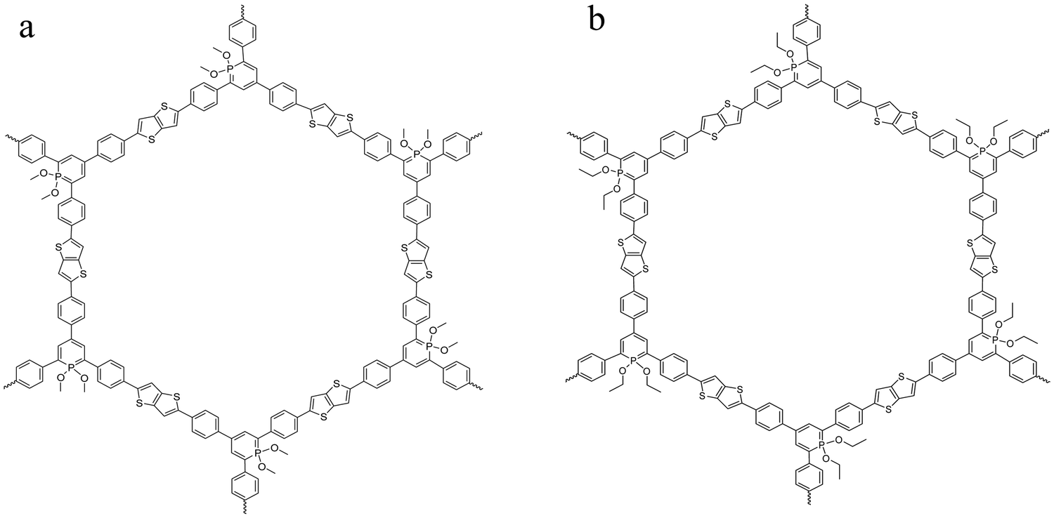 | ||
| Fig. 1 Chemical structure of the investigated COF materials: CPSF-MeO (a, left) and CPSF-EtO (b, right). | ||
The samples were investigated with respect to microporosity by nitrogen adsorption measurements at 77 K. The sorption/desorption isotherms are given in the ESI† in Fig. S4. CPSF-MeO has a BET surface area value of 21.5 m2 g−1 where for CPSF-EtO a value of 92.2 m2 g−1 was estimated. The difference in the surface area values of both compounds is reproducible and significant. These values indicate the presence of a certain micro- or mesoporosity which must be ascribed to the formation of stacks of the 2D sheets. As the BET surface area values are relatively low it is concluded that the stacks are either imperfect or small with respect to their stack height and/or their lateral dimensions. The maximum of the pore size distribution is found at 3.5 nm for CPSF-MeO and 4 nm for CPSF-EtO (see Fig. S5, ESI†). For further details see ESI.† This size scale is also supported by the chemical structure as for the mesoscopic rings in the 2D sheets a theoretical diameter of 3.8 nm can be deduced (see Fig. S6, ESI†). This value coincides well with the experimentally estimated pore size values. This agreement confirms the structure of the 2D sheets with the macrocycle being the building block for the formation for the microporosity by stacking of these sheets.
 . The dielectric data were measured in the frequency range from 10−1 Hz to 106 Hz at the temperature between 173 K and 573 K. A Quatro cryosystem (Novocontrol) was used to control the temperature of the sample with a temperature stability better than 0.1 K employing nitrogen as heating agent. The measurements were carried out in parallel plate geometry using a custom made hermetically sealed dielectric cell. For details see ref. 45. In the cell disk-like stainless steel electrodes are incorporated having an active diameter of 16 mm. The distance between the electrodes was maintained by the construction of the cell and was 100 μm.
Results and discussion
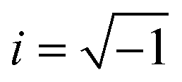
The thermal stability of the COFs was investigated by TGA measurements. Fig. 2 gives the weight loss versus temperature for both materials.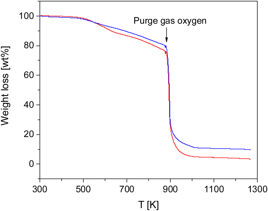 | ||
| Fig. 2 Weight loss versus temperature for both COF materials: blue – CPSF-MeO, red – CPSF-EtO. | ||
Both COF materials are thermally stable up to ca. 500 K (227 °C). For higher temperatures there is a weight loss of ca. 19 and 23% in the temperature range of 500–873 K (227–600 °C) for CPSF-MeO and CPSF-EtO. As the principal structure of the 2D sheets is similar for both materials it might be concluded that the difference in the mass loss is due the different side groups, either directly or indirect due to differences in the lateral size of the sheets or formation of defects or end groups. At 873 K in oxygen atmosphere the samples degrade by oxidation. The residual char, which is remaining carbonaceous material that cannot be further degraded into smaller volatile fragments in the probed temperature range, accounts for 10 and 4% for CPSF-MeO and CPSF-EtO, respectively. For the investigated materials the most probable char promoters are the aromatic groups in the chemical structure. It might be that also phosphorus which is known as a flame-retardant component is involved in the char formation.48
To characterize the morphology of the COF materials first scanning electron microscopy (SEM) is carried out. Fig. 3 gives the SEM images for CPSF-MeO (Fig. 3(a)) and CPSF-EtO (Fig. 3(b)).
 | ||
| Fig. 3 (a) SEM image of CPSF-MeO powder. (b) SEM image of CPSF-EtO powder. The red bars represent a size of 1 μm. | ||
The SEM images show that the bulk COF powers consist of flakes with a size of ca. 10.3 μm for CPSF-MeO and 37.6 μm for CPSF-EtO. These sizes were estimated by statistical image analysis. The “cauliflower-like” structure might indicate a point-nucleation growth mechanism. This means the nucleation starts from a sufficiently large aggregate that its surface to volume ratio is higher than a critical one where the further nucleation is driven by a reduction in the free energy. As the same solvent is used for the synthesis and larger flakes are found for CPSF-EtO this might indicate that during preparation CPSF-EtO precipitate later from the solution. As in the context of the observed microporosity this different appearance might be either an effect of the alkoxy-groups at the phosphorus or rather their effect on the formation of the sheets and/or defects, end groups etc. The figures show also that the flakes have a finer internal structure with elements of smaller sizes. Despite the apparently larger size of the observed flakes the structure of CPSF-EtO seems to be more open than that of CPSF-MeO which agrees with the larger BET surface area of CPSF-EtO.
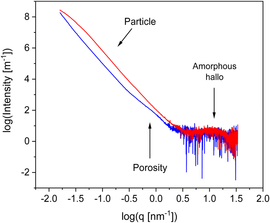
To characterize the materials further X-ray scattering have been carried out. Fig. 4 compares the X-ray pattern for CPSF-MeO and CPSF-EtO. X-ray data have been reported for the comparable system CPF-1 elesewhere.27 For both COF materials the scattering patterns reveal different scattering phenomena. As no sharp Bragg reflections are detected in the WAXS region, and only an amorphous halo is observed, indicating that the samples do not contain significant amounts of crystalline materials and can be considered as largely amorphous. The amorphous halo corresponds to short range correlations between carbon/carbon structures.49 Moreover, such a scattering pattern in the WAXS region is an indication for some disorder in the systems. Therefore, it can be concluded that both COF materials can be considered as glass-like. This is confirmed by the lack of observed first-order phase transitions in conventional differential scanning calorimetry (DSC) experiments. An example for a conventional DSC measurement is given for CPSF-EtO in Fig. S7 (ESI†).
 | ||
| Fig. 4 X-ray pattern for the both COF materials: blue – CPSF-MeO, red – CPSF-EtO. | ||
In the intermediate X-ray scattering range at q values from 0.1 nm−1 to 1 nm−1 the scattering is related to the microporosity of the materials. The scattering at scattering vectors below 0.1 nm−1q can be assigned to the originates from scattering of primary COF particles as discussed below. The data in the SAXS range were analyzed by a Monte-Carlo fitting procedure.44,50 This analysis is based on considering spheres as scattering objects with a minimal set of assumptions regarding the size distribution. This analysis results in histograms of the sphere radii distributions, showing two distinct regions. The obtained histograms are given in the ESI† as Fig. S8 and S9. The first region corresponds to structures with a size distribution between 0 and 10 nm. It is assigned to the micropores formed by the of the COF materials. From that distribution an average pore radius of ca. 3 nm is derived for both COF materials. This value is in reasonable agreement with the data obtained from the nitrogen adsorption measurements. The second region in the histograms with averaged structure sizes larger than 10 nm is related to the distribution of aggregates and/or nanoparticles formed by the COF molecules. Most probably these nanoparticles are formed due to the interaction of the functional groups of the individual COF sheets for instance by π–π interactions. For CPSF-MeO the average value obtained for this part of the particle size distribution is 137 nm. It must be noted that the main population is probably beyond our measurement limit. Therefore, the average radius of 137 nm is based on the measurable range only and might be not correct when only a tail was observed. For CPSF-EtO a sphere radius of 81 nm is obtained. The smaller particle size found for CPSF-EtO might be a further reason for the higher BET surface value found for this material. It is worth to mention that the SEM images and the X-ray scattering pattern reveal no distinct signature of layered aggregates, whereas the BET surface area values indicate the presence of micropores which must be formed by stacks of the COF 2D sheets. Therefore, it can be concluded that the formed stacks are rather small. Following this argumentation and considering the identical size of the macrocyclic structures forming defined mesopores for both COF, it may be further concluded that the fraction of micro- or mesoporosity due to stacked 2D sheets compared to the interstitial volume of bigger aggregates or agglomerates might be larger for CPSF-EtO resulting in a smaller maximum in the size distribution. Consequently, the investigated CPSF-EtO seems to exhibit a stronger tendency to stacking than CPSF-MeO. This is supported by the lager BET surface of CPSF-EtO and its smaller average particle size from the X-ray experiments indicating more mesopores formed by stacking of the 2D sheets.
As discussed above both COF materials can be considered as liquids or glasses. Therefore, the question appears whether CPSF-MeO and CPSF-EtO undergo a glass transition. This is not a trivial question. Here, the individual COF sheets self-assemble into stacks. By this arrangement rotational fluctuations or segmental dynamics – which are usually discussed as the molecular origin of the glass transition for glass forming liquids or polymers – are so restricted that they have to be ruled out. By conventional differential scanning calorimetry, no glass transition could be observed (see Fig. S7, ESI†). This might be ascribed to the thermal response at the glass transition being too low to be detected by conventional DSC. Therefore, fast scanning calorimetry experiments employing a FlashDSC 1 have been carried out. Due to the higher heating rates compared to conventional DSC thermal transitions with a weaker intensity could be detected. Fig. 5 gives the heat flow as a function of temperature for CPSF-MeO (Fig. 5(a)) and CPSF-EtO (Fig. 5(b)) for different heating rates.
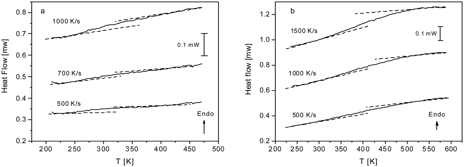 | ||
| Fig. 5 (a) Heat flow versus temperature for CPSF-MeO for the indicated heating rates. (b) Heat flow versus temperature for CPSF-EtO for the indicated heating rates. | ||
A step-like change is observed in the heat flow indicating a glass transition. As expected, the glass transition shifts to higher temperatures with increasing heating rate which is also characteristic for a glass transition. For conventional polymers cooperative segmental dynamics related to conformational changes is discussed as molecular origin for the glass transition. As the individual COF molecules stack together by π–π interactions cooperative bending fluctuation as discussed as a molecular mechanism for the glass transition of PIMs35,36 can also be considered. The observed step-like changes of the heat flow at the glass transition (ΔcP) are small for both materials. Within the experimental uncertainties no significant differences for both materials can be discussed unambiguously.
A glass transition temperature Tg is estimated as the temperature of the half step-height of the heat flow step. As the step in the heat flow is small, the Tg values might be subjected to larger errors. Surprisingly, although the chemical structure of both COF materials is quite similar, the glass transition of CPSF-EtO is ca. 100 K higher than that of CPSF-MeO. For conventional polymers like poly(n-alkyl metharylates) it is known that exchange of a methyl by an ethyl group in each repeat unit leads to an internal plasticization, and thus to a decrease of the glass transition temperature.51 In contrast to that, the result observed for the COFs here indicates that CPSF-EtO has a more rigid or stiffer structure than CPSF-MeO. This can be understood considering the discussion of BET values and particle size distributions above. The larger fraction of better stacked 2D sheets of CPSF-EtO represents overall a higher degree of order and stronger interaction between these sheets. On the other hand, the more amorphous character of the CPSF-MeO allows for an enhanced molecular mobility resulting in a distinctly lower glass transition temperature, even when it is reasonable to assume identical modes of motion for both species.
Assuming cylindrical pores from the ratio of the BET surface areas the ratio of the numbers of the stacked layers can be roughly estimated (see ESI†). Such a consideration reveals the number of stacked layers is on average ca. four times higher for CPSF-EtO compared to that of CPSF-MeO. This confirms the larger fraction of stacked structures in CPSF-EtO causing a more restricted molecular mobility than in CPSF-MeO leading to a higher glass transition temperature.
For a more detailed analysis of the molecular mobility and the glass transition detected by FSC measurements of the dielectric investigations were carried out. Fig. 6 gives the dielectric loss ε′′ versus temperature for different frequencies for CPSF-MeO (a) and CPSF-EtO (c). For both materials a well-pronounced dielectric process is observed. This process has some specific peculiarities: (1) the dielectric strength decreases strongly with increasing frequency; (2) the position of the maximum of its dielectric loss is independent of temperature. These properties indicate that this dielectric mode is not a relaxation process related to a molecular mobility of dipoles. Percolation of electric excitations has been discussed in literature as the origin for such a process.52 Feldman et al. studied the percolation of electric excitations for microporous silica glasses where the analysis leads to an estimation of the porosity.53–55 A similar process was also obtained for a nanocomposite containing a nanoporous filler.56 The investigated conjugated covalent frameworks also reveal a weak porosity. Therefore, the concept of the percolation of electric excitation is also applied here for that process.
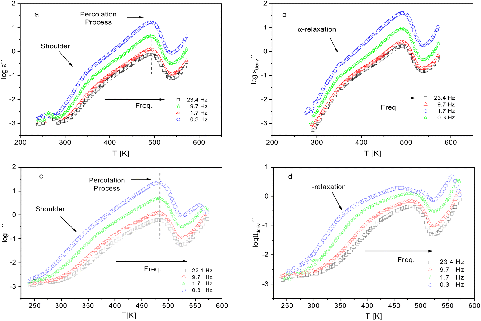 | ||
Fig. 6 (a) Dielectric loss versus temperature for CPSF-MeO at the indicated frequencies. (b)  versus temperature for the same frequencies given in (a). (c) Dielectric loss versus temperature for CPSF-EtO at the indicated frequencies. (d) versus temperature for the same frequencies given in (a). (c) Dielectric loss versus temperature for CPSF-EtO at the indicated frequencies. (d)  versus temperature for the same frequencies given in (c). versus temperature for the same frequencies given in (c). | ||
Although this dominating process observed in the dielectric spectra is not related to molecular mobility of the COF materials, a closer inspection of the dielectric loss shows that there is a low temperature shoulder of the more pronounced percolation process. The shoulder shifts to higher temperatures with increasing frequency which indicates a true relaxation process, called α-relaxation. Due to the weak intensity of this process (as can be seen in Fig. 6(a) and (c)), the data were further analyzed by a technique which is called “conduction-free” dielectric loss  . This approach is based on the derivative of the real part of the complex dielectric function regarding frequency.57 For the Debye function it holds:
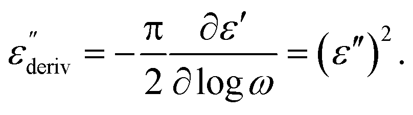 | (1) |
From eqn (1) one can deduce that  shows a peak, like the dielectric loss but due to the square the peak in
  is narrower than that in ε′′ itself. The power of this approach is demonstrated in Fig. 6(b) and (d) which gives the conduction-free loss versus temperature for both materials at the same frequencies as shown in Fig. 6(a) and (c). The shoulder is much more pronounced in that representation and allows for the estimation of the temperature of maximal dielectric loss by fitting a Gaussian to the data for each considered frequency. An example for that analysis is given in the ESI† in Fig. S10. Unfortunately, this analysis could be carried out only in a limited frequency range, as for higher frequencies this relaxation process is overlayed by the percolation process. The estimated maximum temperatures for the α-relaxation are plotted together with the frequency fp in the so-called relaxation map in Arrhenius coordinates (log frequency versus inverse temperature) in Fig. 7 (red circles) for both COF materials.
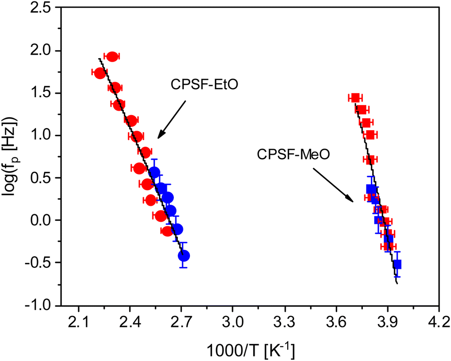 | ||
| Fig. 7 Relaxation rates versus inversus temperature in the Arrhenius diagram: squares – CPSF-MeO; circles – CPSF-EtO. Red – dielectric data; blue – FSC data. The solid lines are common fits of the VFT equation to the dielectric and FSC data for each material. | ||
At first glance the data seem to follow a linear relation and can be described by the Arrhenius equation which is given by
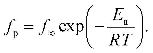 | (2) |
In eqn (2)f∞ is the relaxation rate for infinite temperatures, Ea symbolizes the (apparent) activation energy and R denotes the universal gas constant. A fit of the Arrhenius equation to the data of CPSF-MeO gives an apparent activation energy of 165.2 kJ mol−1 and a prefactor log(f∞ [Hz]) = 33.4. These values are much too high to be discussed on a sound physical basis. For CPSF-EtO an apparent activation energy of 89.9 kJ mol−1 and a prefactor log(f∞ [Hz]) = 12.4 were obtained. Again, the large difference in the glass transition temperatures, and also the large difference in the apparent activation energies shows that both materials behave quite differently although their basic chemical structures are quite similar.
Nevertheless, since the FSC data show a glass transition and the apparent activation energies of the dielectric relaxation processes are high, the temperature dependence of the relaxation rates should rather be considered as glassy dynamics which is better approximated by the empirical Vogel/Fulcher/Tammann (VFT-) equation which reads58
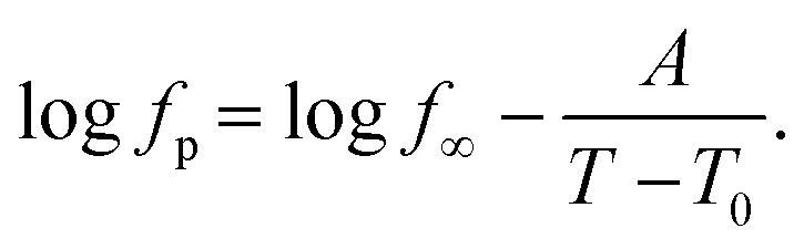 | (3) |
 . The fragility concept can be used to classify glass-forming systems.59 A material is categorized ‘fragile’ if the temperature dependence of the relaxation rates deviates strongly from an Arrhenius-like behavior and ‘strong’ if fp(T) is close to the latter. Fig. 7 shows that the data for both materials can be well described by the VFT approach, which in turn can be considered a clear indication for glassy dynamics. Therefore, the dielectric α-relaxation observed for both COF materials is assigned to the dynamic glass transition. This assignment agrees with thermal data obtained by FSC which also show a glass transition.
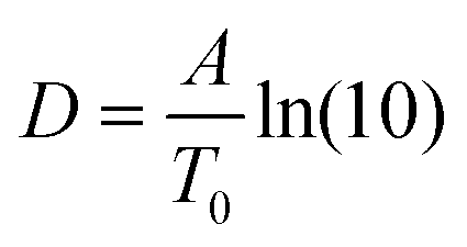
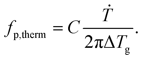
To compare the thermal and the dielectric data, a thermal relaxation rate is calculated from the heating rates in the framework of the fluctuation theory to the glass transition by60
 | (4) |
The dielectric α-relaxation could be measured and analyzed only in a relatively narrow temperature range. Therefore, the fragility strength D cannot be reliably estimated Nevertheless, the data for CPSF-EtO can be better approximated by an Arrhenius equation with a more realistic preexponential factor and apparent activation energy. For that reason, it is concluded here that CPSF-EtO is a stronger glass-former, whereas the glass formation of CPSF-MeO which is more fragile. The large change in the fragility indicates, like the difference in the glass transition temperature, a distinct difference in the interaction of the molecules for both COFs.
Conclusion
Two homologous phosphinine-based covalent organic frameworks denoted as CPSF-MeO and CPSF-EtO have been synthesized. Both form planar aromatic structures, but their chemical structure differs just in ethoxy groups instead of methoxy groups of the phosphinine moieties at the six edges of the macrocyclic structure. Despite of their large similarity significant differences with respect to structure formation, morphology and internal molecular mobility have been observed. Nitrogen adsorption measurements reveal that the materials have moderate BET surface area values below 100 m2 g−1. The maximum of the pore size distribution was found for CPSF-MeO to be 3.5 nm and for CPSF-EtO to be 4 nm coinciding with the geometrical diameter of the macrocycle in the 2D planar sheets of 3.8 nm. This indicates a stacking of these sheets as origin of the respective porosity. The structure of these COF materials was further investigated by scanning electron microscopy. These experiments show that in the bulk COFs form small flakes with average sizes of 10.3 μm for CPSF-MeO and 37.6 μm for CPSF-EtO. These flakes have a finer internal structure. Therefore, the materials were further investigated by X-ray scattering combining SAXS and WAXS measurements. The data in the WAXS range show that the materials are amorphous and can be considered as glass-like. Further the X-ray measurements reveal the porosity of the materials with an average pore radius of 4 nm. This value agrees well with the data obtained by the nitrogen adsorption measurements and the geometry of the macrocyclic structures. Moreover, X-ray investigations show also that the flakes consist of nanoparticles with an average size of at least 137 nm for CPSF-MeO and 81 nm for CPSF-EtO. Most likely these nanoparticles are formed by the interaction of stacked COF molecules.As the both COF materials were found to be amorphous, CPSF-MeO and CPSF-EtO are further investigated by fast scanning calorimetry. These investigations reveal that both materials undergo a glass transition. With this observation it was shown for the first time that amorphous COF show a glass transition. Surprisingly, the glass transition temperature of CPSF-EtO is found to be 100 K higher than for CPSF-MeO although the differences in the chemical structure are quite small. The large difference in the glass transition temperatures is discussed considering a different stacking behavior of both COF molecules. It is assumed that CPSF-EtO forms larger well-defined aggregates that CPSF-MeO, which shows a less ordered and more amorphous character. This assumption is supported by the ca. 4 times larger BET surface area value measured for CPSF-EtO. To investigate the glass transition of these materials further dielectric measurements were carried out. The dielectric spectra reveal two processes. The process observed at higher temperatures has some unusual properties as its temperature position is independent of temperature. This process cannot be considered as a relaxation process related to the molecular mobility in the system. This process is rather assigned to electrical percolation related to the porosity. A second process is observed as a low temperature shoulder of the percolation process. Its position shifts to higher temperatures with increasing frequency indicating a relaxation process related to molecular mobility. The process was analyzed quantitatively via the so-called conduction-free loss approach. With the obtained relaxation rates an Arrhenius diagram was constructed. The dielectric data agree well in their temperature dependence and their absolute values with data obtained by fast scanning calorimetry. This quantitative agreement of the data proved the observed relaxation process in dielectric spectroscopy being a dynamic glass transition. To gain a better understanding and identifying the motional origin of the relaxation process the obtained results must be confirmed for other amorphous COF systems.
Conflicts of interest
The authors declare no competing financial interest.References
- S.-Y. Ding and W. Wang, Covalent organic frameworks (COFs): from design to applications, Chem. Soc. Rev., 2013, 42, 548–568 RSC.
- W. Zhao, L. Xia and X. Liu, Covalent organic frameworks (COFs) perspective of industrialization, CrystEngComm, 2018, 20, 1623–1634 Search PubMed.
- N. G. McCrum; C. P. Buckley and C. B. Bucknall, Principles of polymer engineering, Oxford University Press, New York, 1997 Search PubMed.
- A. J. Blake, N. R. Chapness, M. Crew and S. Parson, Sawhorse connections in a Ag(I)-nitrite coordination network: {[Ag(pyrazine)]NO2}∞, New J. Chem., 1999, 23, 13–15 RSC.
- R. Dawson, A. I. Cooper and D. J. Adams, Nanoporous organic polymer networks, Prog. Polym. Sci., 2011, 37, 530–563 CrossRef.
- S. Wan, J. Guo, J. Kim, H. Ihee and D. Jiang, A belt-shaped, blue luminescent, and semiconducting covalent organic framework, Angew. Chem., Int. Ed., 2008, 47, 8826–8830 CrossRef CAS PubMed.
- N. Huang, P. Wang and D. Jiang, Covalent organic frameworks: a materials platform for structural and functional designs, Nat. Rev. Mater., 2016, 1, 16068 CrossRef CAS.
- C. S. Diercks and O. M. Yaghi, The atom, the molecule, and the covalent organic framework, Science, 2017, 355, eaal1585 CrossRef PubMed.
- R. P. Bisbey and W. R. Dichtel, Covalent Organic Frameworks as a Platform for Multidimensional Polymerization, ACS Cent. Sci., 2017, 3, 533–543 CrossRef CAS PubMed.
- M. Matsumoto, R. R. Dasari, W. Ji, C. H. Feriante, T. C. Parker, S. R. Marder and W. R. Dichtel, Radip, low temperature formation of imine-linked covalent organic frameworks catalyzed by metal triflates, J. Am. Chem. Soc., 2017, 139, 4999–5002 CrossRef CAS PubMed.
- E. Vitaku and W. R. Dichtel, Synthesis of 2D imine-linked covalent organic frameworks through formal transamination recation, J. Am. Chem. Soc., 2017, 139, 12911–12914 CrossRef CAS.
- D. Schwarz, A. Amitava, A. Ichangi, Y. S. Kochergin, P. Lyu, M. V. Opanasenko, J. Tarábek, J. Vacek Chocholoušová, J. Vacek, J. Schmidt, P. Nachtigall, A. Thomas and M. J. Bojdys, Tuning the porosity and photocatalytic performance of triazinebased graphdiyene polymers via polymorphism, ChemSusChem, 2019, 12, 194–199 CrossRef CAS PubMed.
- Y. S. Kochergin, D. Schwarz, A. Acharjya, A. Ichangi, R. Kulkarni, P. Eliášová, J. Vacek, J. Schmidt, A. Thomas and M. J. Bojdys, Exploring the “Goldilocks Zone” of semiconducting photocatalysts by donor-acceptor interactions, Angew. Chem., Int. Ed., 2018, 57, 14188–14192 CrossRef CAS PubMed.
- X. Zou, H. Ren and G. Zhu, Topology-directed design of porous organic frameworks and their advanced applications, Chem. Commun., 2013, 49, 3925–3936 RSC.
- T. Ben and S. Qiu, Porous aromatic frameworks: Synthesis, structure and functions, CrystEngComm, 2013, 15, 17–26 RSC.
- R. Dawson and A. Trewin, Conjugated microporous polymers, in Porous Polymers, ed. T. Ben and S. Qiu, 2015, pp. 155–185 Search PubMed.
- W. Lu, D. Yuan, D. Zhao, C. I. Schilling, O. Plietzsch, T. Muller, S. Bräse, J. Guenther, J. Blümel, Z. Li, H. C. Zhou and R. Krishna, Porous Polymer Networks: Synthesis, Porosity, and Applications in Gas Storage/Separation, Chem. Mater., 2010, 22, 5964–5972 CrossRef CAS.
- J. X. Jiang, F. Su, A. Trewin, C. D. Wood, N. L. Campbell, H. Niu, C. A. Dickinson, Y. Ganin, M. J. Rosseinsky and Y. Z. Khimyak, Conjugated microporous poly(aryleneethynylene) networks, Angew. Chem., Int. Ed., 2007, 46, 8574–8578 CrossRef CAS PubMed.
- X. Liu, Y. Xu and D. Jiang, Conjugated Microporous Polymers as Molecular Sensing Devices: Microporous Architecture Enables Rapid Response and Enhances Sensitivity in Fluorescence-On and Fluorescence-Off Sensing, J. Am. Chem. Soc., 2012, 134, 8738–8741 CrossRef CAS PubMed.
- Y. Xu, S. Jin, H. Xu, A. Nagai and D. Jiang, Conjugated microporous polymers: design, synthesis and application, Chem. Soc. Rev., 2013, 42, 8012–8031 RSC.
- G. Algara-Siller, N. Severin, S. Y. Chong, T. Björkman, R. G. Palgrave, A. Laybourn, M. Antonietti, Y. Z. Khimyak, A. V. Krasheninnikov, J. P. Rabe, U. Kaiser, A. I. Cooper, A. Thomas and M. J. Bojdys, Triazine-Based Graphitic Carbon Nitride: a Two-Dimensional Semiconductor, Angew. Chem., 2014, 126, 7580–7585 CrossRef.
- P. Katekomol, J. R. M. Roeser, M. J. Bojdys, J. Weber and A. Thomas, Covalent triazine frameworks prepared from 1,3,5-tricyanobenzene, Chem. Mater., 2013, 25, 1542–1548 CrossRef CAS.
- S. Ren, M. J. Bojdys, R. Dawson, A. Laybourn, Y. Z. Khimyak, D. J. Adams and A. I. Cooper, Porous, fluorescent, covalent triazine-based frameworks via room-temperature and microwave-assisted synthesis, Adv. Mater., 2012, 24, 2357–2361 CrossRef CAS.
- M. J. Bojdys, J. Jeromenok, A. Thomas and M. Antonietti, Rational extension of the family of layered, covalent, triazine-based frameworks with regular porosity, Adv. Mater., 2010, 22, 2202–2205 CrossRef CAS PubMed.
- D. Schwarz, A. Acharja, A. Ichangi, P. Lyu, M. V. Opanasenko, F. R. Goßler, T. A. König, J. Čejka, P. Nachtigall and A. Thomas, Tailored Band Gaps in Sulfur- and Nitrogen-Containing Porous Donor–Acceptor Polymers, Chem. – Eur. J., 2018, 24, 11916–11921 CrossRef CAS PubMed.
- J. Roeser, D. Prill, M. J. Bojdys, P. Fayon, A. Trewin, A. N. Fitch, M. U. Schmidt and A. Thomas, Anionic silicate organic frameworks constructed from hexacoordinate silicon centres, Nat. Chem., 2017, 9, 977–982 CrossRef CAS PubMed.
- J. Huang, J. Tarábek, R. Kulkarni, C. Wang, M. Dračínský, G. J. Smales, Y. Tian, S. Ren, B. R. Pauw, U. Resch-Genger and M. J. Bojdys, A π-Conjugated, Covalent Phosphinine Framework, Chem. – Eur. J., 2019, 25, 12342–12348 CrossRef CAS PubMed.
- A. Thomas, Functional Materials: From Hard to Soft Porous Frameworks, Angew. Chem., Int. Ed., 2010, 49, 8328–8344 CrossRef CAS.
- Y. Xu, Z. Lin, X. Huang, Y. Wang, Y. Huang and X. Duan, Functionalized graphene hydrogel-based high-performance supercapacitors, Adv. Mater., 2013, 25, 5779–5784 CrossRef CAS.
- W. Lu, D. Yuan, J. Sculley, D. Zhao, R. Krishna and H.-C. Zhou, Sulfonate-Grafted Porous Polymer Networks for Preferential CO2 Adsorption at Low Pressure, J. Am. Chem. Soc., 2011, 133, 18126–18129 CrossRef CAS PubMed.
- S. B. Alahakoon, C. M. Thompson, G. Occhialini and R. A. Smaldone, Design Principles for Two-Dimensional Covalent Organic Frameworks for Applications in Energy Storage, ChemSusChem, 2017, 10, 2116–2129 CrossRef CAS PubMed.
- S. Frunza, A. Schönhals, L. Frunza, P. Ganea, H. Kosslick, J. Harloff and A. Schulz, Molecular relaxation processes in a MOF-5 structure revealed by broadband dielectric spectroscopy: signature of phenylene ring fluctuations, J. Phys. Chem. B, 2010, 114, 12840 CrossRef CAS PubMed.
- N. Konnertz, Y. Ding, J. W. Harrison, P. M. Budd, A. Schönhals and M. Böhning, Molecular mobility of the high performance membrane polymer PIM-1 as investigated by dielectric spectroscopy, ACS Macro Lett., 2016, 5, 528–532 CrossRef CAS PubMed.
- F. Emamverdi, H. Yin, G. J. Smales, W. J. Harrison, P. M. Budd, M. Böhning and A. Schönhals, Polymers of Intrinsic Microporosity – Molecular Mobility and Physical Aging Revisited by Dielectric Spectroscopy and X-Ray Scattering, Macromolecules, 2022, 55, 7340–7350 CrossRef CAS.
- H. Yin, B. Yang, Y. Z. Chua, P. Szymoniak, M. Carta, R. Malpass-Evans, N. McKeown, W. J. Harrison, P. M. Budd, C. Schick, M. Böhning and A. Schönhals, Effect of Backbone Rigidity on the Glass Transition of Polymers of Intrinsic Microporosity Probed by Fast Scanning Calorimetry, ACS Macro Lett., 2019, 8, 1022–1028 CrossRef CAS PubMed.
- H. Yin, Y. Chua, B. Yang, C. Schick, W. Harrison, P. M. Budd, M. Böhning and A. Schönhals, First clear-cut experimental evidence of a glass transition in a polymer with intrinsic microporosity: PIM-1, J. Chem. Phys. Lett., 2018, 9, 2003–2008 CrossRef CAS PubMed.
- H. Yin, P. Chapala, M. Bermeshev, B. R. Pauw, A. Schönhals and M. Böhning, Influence of trimethylsilyl side groups on the molecular mobility and charge transport in highly permeable glassy polynorbornenes, ACS Appl. Polym. Mater., 2019, 1, 844–855 CrossRef CAS.
- H. Yin, P. Chapala, M. Bermeshev, A. Schönhals and M. Böhning, Molecular mobility and physical aging of a highly permeable glassy polynorbornene as revealed by dielectric spectroscopy, ACS Macro Lett., 2017, 6, 813–818 CrossRef CAS.
- D. Schwarz, Y. S. Kochergin, A. Acharja, A. Ichangi, M. V. Opanasenko, J. Čejka, U. Lappan, P. Arki, J. He and J. Schmidt, Tailored Band Gaps in Sulfur- and Nitrogen-Containing Porous Donor–Acceptor Polymers, Chem. – Eur. J., 2017, 23, 13023–13027 CrossRef CAS PubMed.
- R. S. Sprick, B. Bonillo, M. Sachs, R. Clowes, J. R. Durrant, D. J. Adams and A. I. Cooper, Chem. Commun., 2016, 52, 10008–10011 RSC.
- G. J. Smales and B. R. Pauw, The MOUSE Project: A Meticulous Approach for Obtaining Traceable, Wide-Range X-Ray Scattering Information, J. Inst., 2021, 16, P06034 CAS.
- J. Filik, A. W. Ashton, P. C. Y. Chang, P. A. Chater, S. J. Day, M. Drakopoulos, M. W. Gerring, M. L. Hart, O. V. Magdysyuk, S. Michalik, A. Smith, C. C. Tang, N. J. Terrill, M. T. Wharmby and H. Wilhelm, Processing Two-Dimensional X-Ray Diffraction and Small-Angle Scattering Data in DAWN 2, J. Appl. Crystallogr., 2017, 50, 959–966 CrossRef CAS PubMed.
- B. R. Pauw, A. J. Smith, T. Snow, N. J. Terrill and A. F. Thünemann, The Modular Small-Angle X-Ray Scattering Data Correction Sequence, J. Appl. Crystallogr., 2017, 50, 1800–1811 CrossRef CAS PubMed.
- I. Breßler, B. R. Pauw and A. Thünemann, McSAS: software for the retrieval of model parameter distributions from scattering patterns, J. Appl. Crystallogr., 2015, 48, 962–969 CrossRef PubMed.
- S. Roy and R. Richert, Dielectric spectroscopy study of myoglobin in glycerol-water mixtures, Biochim. Biophys. Acta, 2014, 1844, 323–329 CrossRef CAS PubMed.
- V. Mathot, M. Pyda, T. Pijpers, G. Van den Poel, E. van de Kerkhof, S. van Herwaarden, F. van Herwaarden and A. Leenaers, The Flash DSC 1, a power compensation twin-type, chip-based fast scanning calorimeter (FSC): First findings on polymers, Thermochim. Acta, 2011, 522, 36 CrossRef CAS.
- J. E. K. J. Schawe, Influence of processing conditions on polymer crystallization measured by fast scanning DSC, Therm. Anal. Calorim., 2014, 116, 1165 CrossRef CAS.
- B. Schartel, Phosphorus-based Flame Retardancy Mechanisms—Old Hat or a Starting Point for Future Development?, Materials, 2010, 3, 4710–4745 CrossRef CAS PubMed.
- G. W. Stewart, Theory of X-ray diffraction in liquids, Phys. Rev., 1928, 32, 558 CrossRef CAS.
- B. R. Pauw, J. S. Pedersen, S. Tardif, M. Takata and B. B. Iversen, Improvements and considerations for size distribution retrieval from small-angle scattering data by Monte Carlo methods, J. Appl. Crystallogr., 2013, 46, 365–371 CrossRef CAS PubMed.
- F. Garwe, A. Schönhals, H. Lockwenz, M. Beiner, K. Schröter and E. Donth, Influence of cooperative α-dynamics on local β relaxations in the αβ splitting region of the glass transition in poly (n alkyl methacrylate)s, Macromolecules, 1996, 29, 247–253 CrossRef CAS.
- P. Pissis, J. Laudat, D. Daoukaki and A. Kyritsis, Dynamic properties of water in porous Vycor glass, J. Non-Cryst. Solids, 1994, 171, 201–207 CrossRef CAS.
- A. Puzenko, N. Kozlovich, A. Gutina and Y. Feldman, Determination of pore fractal dimensions and porosity of silica glasses from the dielectric response at percolation, Phys. Rev. B: Condens. Matter Mater. Phys., 1999, 60, 14348 CrossRef CAS.
- A. Gutina, T. Antropova, E. Rysiakiewicz-Pasek, K. Virnik and Y. Feldman, Dielectric relaxation in porous glasses, Microporous Mesoporous Mater., 2003, 58, 237–254 CrossRef CAS.
- Y. Feldman, A. Puzenko and Y. Ryabov, Non-Debye dielectric relaxation in complex materials, Chem. Phys., 2002, 284, 139–168 CrossRef CAS.
- P. J. Purohit, J. E. Huacuja-Sánchez, D. Y. Wang, F. Emmerling, A. Thünemann, G. Heinrich and A. Schönhals, Structure–property relationships of nanocomposites based on polypropylene and layered double hydroxides, Macromolecules, 2011, 44, 4342–4354 CrossRef CAS.
- M. Wübbenhorst and J. van Turnhout, Analysis of Complex Dielectric Spectra. I. One-Dimensional Derivative Techniques and Three-Dimensional Modelling, J. Non-Cryst. Solids, 2002, 305, 40–49 CrossRef.
- H. Vogel, The temperature dependence law of the viscosity of fluids, Phys. Z., 1921, 22, 645 Search PubMed; G. S. Fulcher, Analysis of Recent Measurements of the Viscosity of Glasses, J. Am. Ceram. Soc., 1925, 8, 339–355 CrossRef CAS; G. Tammann and G. Hesse, The dependency of viscosity on temperature in hypothermic liquids, Z. Anorg. Allg. Chem., 1926, 156, 245–257 CrossRef.
- C. A. Angell, Entropy and fragility in supercooling liquids, J. Res. Natl. Inst. Stand. Technol., 1997, 102(2), 171 CrossRef CAS PubMed.
- E. Donth, The size of cooperatively rearranging regions at the glass transition, J. Non-Cryst. Solids, 1982, 53, 325–330 CrossRef CAS.
- J. E. K. Schawe, Vitrification in a wide cooling rate range: The relations between cooling rate relaxation time, transition width, and fragility, J. Chem. Phys., 2014, 141, 184905 CrossRef PubMed.
- K. Schneider, A. Schönhals and E. Donth, Über die Größe der kooperativen Umlagerungsbereiche am thermischen Glasübergang amorpher Polymerer, Acta Polym., 1981, 32, 471–475 CrossRef CAS.
- B. H. Monjezi, K. Kutonova, M. Tsotsalas, S. Henke and A. Knebel, Current trends in metal-organic and covalent organic framework membrane materials, Angew. Chem., Int. Ed., 2021, 60, 15153–15164 CrossRef PubMed.
- J. Song, L. Frentzel-Beyme, R. Pallach, P. Kolodzeiski, A. Koutsianos, W.-L. Xue, R. Schmid and S. Henke, Modulating Liquid-liquid transitions and glass formation in zeolitic imidazolate frameworks by decoration with electron-withdrawing cyano group, J. Am. Chem. Soc., 2023, 145, 9273–9284 CrossRef CAS PubMed.
Footnote |
| † Electronic supplementary information (ESI) available: Reaction scheme and elementary composition; sorption measurements; theoretical pore size, conventional scanning calorimetry; analysis of the X-ray measurements; analysis of the X-ray measurements. Estimation of the ratio of the number of layers in the COF aggregates. See DOI: https://doi.org/10.1039/d3ma01123b |
| This journal is © The Royal Society of Chemistry 2024 |