
 Open Access Article
 This Open Access Article is licensed under a
 Creative Commons Attribution 3.0 Unported Licence
Metal–organic framework-derived hierarchical porous N/Co-doped carbon-supported sponge-like Pd–SnO2 nanostructures for low-temperature CO oxidation†
Adewale K.
Ipadeola
 ab,
Ahmed
Gamal
abc,
Belal
Salah
ab,
Yassmin
Ibrahim
ab,
Aboubakr M.
Abdullah
*a,
Aderemi B.
Haruna
c,
Kenneth I.
Ozoemena
*c and
Kamel
Eid
*b
ab,
Ahmed
Gamal
abc,
Belal
Salah
ab,
Yassmin
Ibrahim
ab,
Aboubakr M.
Abdullah
*a,
Aderemi B.
Haruna
c,
Kenneth I.
Ozoemena
*c and
Kamel
Eid
*b
aCenter for Advanced Materials, Qatar University, Doha 2713, Qatar. E-mail: bakr@qu.edu.qa
bGas Processing Center (GPC), College of Engineering, Qatar University, Doha 2713, Qatar. E-mail: kamel.eid@qu.edu.qa
cMolecular Sciences Institute, School of Chemistry, University of the Witwatersrand, Private Bag 3, PO Wits, Johannesburg 2050, South Africa. E-mail: Kenneth.ozoemena@wits.ac.za
First published on 3rd January 2024
Abstract
Metal–organic framework-derived porous N/Co-doped carbon (MOF-PNC) nanostructures-supported metal nanoparticles (NPs) are of great importance in multidisciplinary catalytic reactions; however, their catalytic performance toward low-temperature CO oxidation (COOxid) is rarely reported. Herein, a MOF-PNC-supported Pd–SnO2 (Pd–SnO2/MOF-PNC) was synthesized via a microwave-irradiation (MW-I), annealing, and chemical etching approach for thermal COOxid. The as-prepared Pd–SnO2/MOF-PNC had hierarchical porous sponge-like nanostructures composed of porous two-dimensional ultrathin nanosheets (NSs), co-doped with N/Co, with a high specific surface area (185.40 m2 g−1) and pore volume (0.045 cm3 g−1), and ornamented with Pd–SnO2 NPs (7.79 ± 1.42 nm). These merits endowed the Pd–SnO2/MOF-PNC with excellent thermal catalytic COOxid activity at a low complete CO conversion temperature (T100 = 65.6 °C) compared to those of Pd(1%)–SnO2/MOF-PNC (165.2 °C), Pd–SnO2 (199.1 °C), Pd/MOF-PNC (107.9 °C) and commercial Pd/C catalysts (201.2 °C), due to the augmented electronic interaction and synergy of Pd NPs with oxygen-rich SnO2 supports and Co–Nx active sites in MOF-PNC. Thus, coupling two supports (i.e., SnO2/MOF-PNC) is more crucial for promoting the low-temperature COOxid activity of Pd NPs.
Introduction
The global energy demand has increased substantially in the last few decades and is expected to continue to rise owing to the inevitable industrialization and civilization.1–3 Limitless efforts to solve these issues lie in developing green energy technologies (i.e., fuel cells,4 batteries,5 and water splitting6,7) and gas conversion reactions.8–10 COOxid is formed during heterogeneous catalysis electrochemically,11,12 or thermally,13–16 but the latter is feasible for large-scale applications. Pd-based catalysts are among the most active catalysts for thermal COOxid, however, the high cost and earth-rarity of Pd are critical barriers.17 Using metal oxide supports (SnO2, SiO2, Fe2O3, TiO2, and CeO2) could boost the catalytic performance and stability, and reduce the cost.18,19 Also, the electronic interaction and synergy of Pd with metal oxide supports enhances the activation/dissociation of CO/O2 reactants and quickly desorbs intermediate species (i.e., carbonate/formate) and products (i.e., CO2). For instance, the Pd/MgO-h-BN catalyst showed a lower complete CO conversion temperature (T100 = 140 °C) than Pd/MgO (180 °C), but Pd/h-BN could not achieve T100, due to the interaction of Pd with the MgO-h-BN support that enhanced the large amount of adsorbed O2 and rapidly desorbed the intermediates.20 Pd@SiO2-673-CeO2 catalysts had great thermal COOxid at a lower T100 (92 °C) than Pd@SiO2-673 (130 °C), owing to the interaction of Pd with dual supports (i.e., SiO2 and CeO2).21Unlike other supports, metal–organic framework-derived porous N/Co-doped carbon (MOF-PNC) nanostructures possess outstanding features (i.e. thermal/chemical stability and impressive surface area), and rich metal-Nx active sites,22–24 which are beneficial for uniform distribution and stabilization of Pd NPs.25–27 In addition, they make Pd active sites readily accessible and maximize their utilization for thermal COOxid.28–30 For instance, porous C-supported Cu/Cu2O nanojunctions derived from (Cu-BTC)-MOF had impressive COOxid activity achieved at T100 (155–190 °C),31 due to a high ratio of Cu metal phases (Cu0, Cu+, and Cu2+) and interaction with the porous C support. Noticeably, MOF-PNC-supported metal NPs are not emphasized enough, particularly using SnO2 as a co-support, for thermal COOxid, and their effect remains ambiguous.24,32–34
Herein, MOF-PNC-supported Pd–SnO2 (Pd–SnO2/MOF-PNC) exhibited hierarchical porous sponge-like nanostructures comprising porous 2D ultrathin MOF-PNC NSs with abundant N/Co dopants, large specific surface area (185.40 m2 g−1), and encapsulated spherical-like Pd–SnO2 NPs (7.79 ± 1.42 nm). Coupling the properties of SnO2 (i.e., ease of adsorption and activation/dissociation of CO/O2) and the merits of MOF-PNC (i.e., high surface area and rich metal-Nx active sites) can ease CO oxidation on Pd at a low temperature and enhanced durability. The thermal COOxid activities of Pd–SnO2/MOF-PNC, Pd(1%)–SnO2/MOF-PNC, Pd–SnO2, SnO2/MOF-PNC and Pd/MOF-PNC are benchmarked to commercial Pd/C catalysts in order to estimate the effect of the supports.
Materials and methods
Materials
Potassium tetrachloropalladate(II) (K2PdCl4 ≥ 98%), tin(II) chloride dihydrate (SnCl2·2H2O ≥ 98%), cobalt(II) nitrate hexahydrate (Co(NO3)2·6H2O ≥ 94.5%), biphenyl-4,4′-dicarboxylic acid (BPDC ≥ 97%), ethylene glycol (EG ≥ 99.8%), triethyleneamine (TEA ≥ 99.5%), dimethylformamide (DMF ≥ 99.8%), and commercial Pd/C catalyst (20 wt%) were purchased from Sigma-Aldrich Chemie GmbH (Munich, Germany).Preparation of MOF-derived porous Co/N-doped carbon (MOF-PNC)
MOF-PNC was synthesized by mixing Co(NO3)·6H2O (0.44 g), BPDC (0.36 g), TEA (1.5 mL) and DMF (50 mL) under magnetic stirring at 25 °C, then microwave-irradiated at 600 W for 30 min.33 The obtained precipitates were washed and dried in a vacuum oven at 60 °C, followed by annealing at 800 °C for 5 h. The obtained powder was soaked in an aqueous solution of HCl (3 M) for 24 h, washed, and dried to give MOF-PNC.Preparation of SnO2/MOF-PNC
SnO2/MOF-PNC was prepared by magnetically stirring SnCl2·2H2O (47.8 mg) in a mixture of EG and water (4![[thin space (1/6-em)]](https://www.rsc.org/images/entities/char_2009.gif) :1 by volume); then, MOF-PNC (100 mg) was added and the mixture was microwave-irradiated at 600 W for 1 h. The resulting product (SnO2/MOF-PNC) was washed and dried at 80 °C for 4 h under vacuum.
:1 by volume); then, MOF-PNC (100 mg) was added and the mixture was microwave-irradiated at 600 W for 1 h. The resulting product (SnO2/MOF-PNC) was washed and dried at 80 °C for 4 h under vacuum.
Preparation of Pd–SnO2/MOF-PNC
The as-prepared SnO2/MOF-PNC (100 mg) was mixed with K2PdCl4 (61.35 mg) in EG (50 mL) at a pH of 12 with NaOH under magnetic stirring at 25 °C for 30 min, followed by microwave-irradiation at 600 W for 1 h (Anton Paar – Multiwave 3000).35 Then, the mixture's pH was lowered to 3 using 0.1 M HNO3, and it was washed thoroughly with deionized H2O, and dried at 80 °C for 4 h under a vacuum to afford Pd–SnO2/MOF-PNC. A similar method was used for the preparation of Pd(1%)–SnO2/MOF-PNC (1 wt% Pd loading) and Pd–SnO2.Preparation of Pd/MOF-PNC
Pd/MOF-PNC was prepared by mixing MOF-PNC (100 mg) with K2PdCl4 (61.35 mg) in EG (50 mL) under magnetic stirring at 25 °C for 30 min and the pH was adjusted to 12 using NaOH solution (1 M). Then, the solution was placed in a microwave and irradiated at 600 W for 1 h.35 Finally, the mixture's pH was decreased to 3 using 0.1 M HNO3, washed with deionized H2O, and dried at 80 °C for 4 h under vacuum.Characterisation
The morphology and composition analysis were conducted on a scanning electron microscope (SEM, Hitachi S-4800, Hitachi, Tokyo, Japan) and transmission electron microscope (TEM, TecnaiG220, FEI, Hillsboro, OR, USA) equipped with an energy dispersive spectrometer (EDS). The electronic structure and surface composition were carried out by X-ray photoelectron spectroscopy ((XPS) Ultra DLD XPS Kratos, Manchester, UK). The powder X-ray diffraction pattern (XRD) was measured on an X-ray diffractometer (X'Pert-Pro MPD, PANalytical Co., Almelo, Netherlands). The N2-physisorption isotherms were measured on a Quanta chrome Autosorb-1 analyzer (Quanta chrome Instrument Corporation). The Fourier transform infrared spectra (FT-IR) were recorded on a Thermo Nicolet Nexus 670 FT-IR spectrometer (Thermo Scientific).Thermal CO oxidation reaction
The thermal CO oxidation reaction was carried out in a fixed bed quartz tubular reactor connected to an online gas analyzer (Mass spectra, HIDEN ANALYTICAL the HPR-20 System) using 50 mg of each catalyst at the same Pd loading amount (20 wt%).36 The catalyst was packed with quartz wool and fixed in the reactor and then pretreated at 200 °C (5 °C min−1 heating ramp) under O2 (5% in Ar) with a flow rate of 20 mL min−1 for 1 h and subsequently under H2 (5% in Ar) with a flow rate of 20 mL min−1 for 1 h. After cooling to 25 °C, the catalyst was exposed to the gas mixture (O2 (20%) + CO (4%) + Ar (76%)) at a flow rate of 20 mL min−1 under heating to 300 °C (5° min−1 ramping rate).36 All the catalysts were subjected to the same treatment before the thermal CO oxidation. The percentage of CO conversion (%CO) was calculated using the following (eqn (1)): | (1) |
The CO temperature-programmed desorption (CO-TPD) was conducted by the initial pretreatment of each catalyst (50 mg) under Ar (50 mL min−1 flow rate) at 300 °C (5 °C min−1) for 1 h in a Micromeritics ChemiSorb 2750 analyzer equipped with a thermal conductivity detector (TCD). After cooling to room temperature, the catalysts were exposed to (4% CO + 96% Ar) at a flow rate of 30 mL min−1 for 30 min under heating to 350 °C (5 °C min−1).36
The H2 temperature-programmed reduction (H2-TPR) was measured by an initial pretreatment under Ar (50 mL min−1) at 300 °C (10 °C min−1) for 1 h and then exposed to (5% H2 + 95% Ar) at a flow rate of 30 mL min−1 under heating to 350 °C (5 °C min−1).36
The O2 temperature-programmed oxidation (O2-TPO) was studied by initial treatment under Ar at a flow rate of 50 mL min−1 at 300 °C (5 °C min−1) for 1 h and then exposed to (20% O2 + 80% Ar) at a flow rate of 30 mL min−1 under heating to 350 °C (20 °C min−1).
To get more insights into the thermal CO oxidation, the CO oxidation rate (rCO) of the catalysts was calculated at different CO conversion temperatures (10, 20, 50, and 80 °C) based on total gas flow (VGas), initial concentration of CO (XCO), and molar weight of catalyst (MCat) using eqn (2).
 | (2) |
 | (3) |
Results and discussion
The Pd–SnO2/MOF-PNC was synthesized via the MW-I of Co(NO3)·6H2O with biphenyl-4,4′-dicarboxylic acid (BPDC) and triethyleneamine (TEA) in dimethylformamide (DMF) solution to form a MOF, which was annealed and etched in HCl solution to afford MOF-PNC NSs (Fig. 1a).33 This was followed by MW-I with the Sn precursor and then K2PdCl4 in ethylene glycol (EG) to give Pd–SnO2/MOF-PNC.35 The SEM of Pd–SnO2/MOF-PNC shows hierarchical porous sponge-like nanostructures (Fig. 1b), composed of porous 2D sheet-supported Pd NPs, with mean size (7.79 ± 1.42 nm), proved by TEM (Fig. 1c and d), which is important for stabilizing the Pd NPs against aggregation during the COOxid. The lattice fringe (0.229 nm) of the Pd NPs is assigned to the {111} facet of face-center-cubic (fcc) Pd (Fig. 1e),35 and the selected area electron diffraction pattern (SAED) reveals the typical rings of Pd (Fig. 1f).35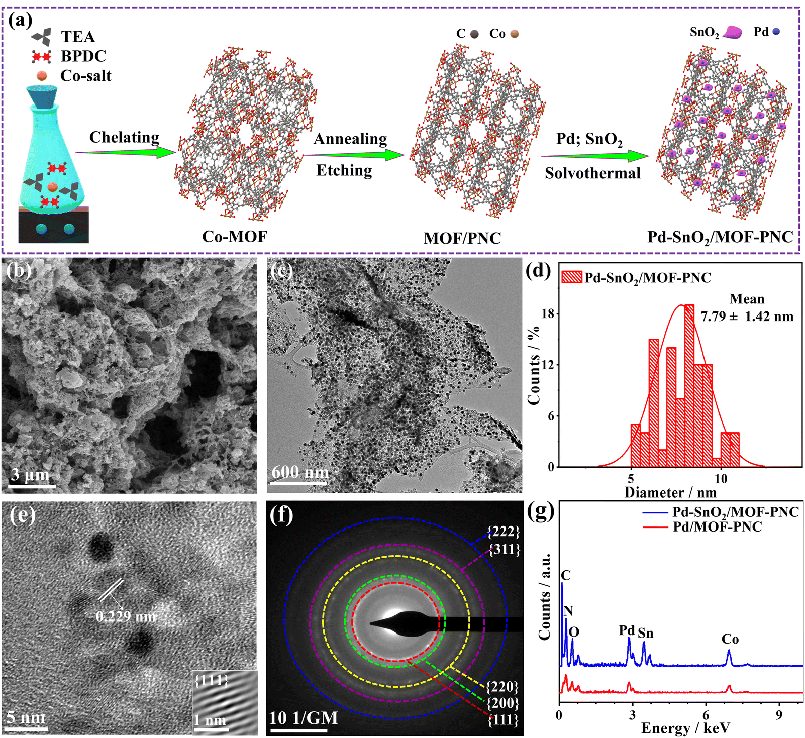 | ||
| Fig. 1 (a) Schematic synthesis, (b) SEM, (c) TEM, (d) NPs size distribution, (e) HRTEM, (f) SAED of Pd–SnO2/MOF-PNC and (g) EDX of Pd–SnO2/MOF-PNC and Pd/MOF-PNC. | ||
The EDX reveals the presence of Pd/Sn/Co/N/C/O with atomic contents (2.44/4.80/2.74/9.14/66.76/14.11 at%), indicating the successful formation of Pd/SnO2 over MOF-PNC; however, Pd/MOF-PNC shows the existence of Pd/Co/N/C/O with contents (2.12/4.39/20.54/49.81/23.24 at%) (Fig. 1g) and uniform distribution mapped (Fig. S1, ESI†). Bulk and actual metal contents (Pd/Sn/Co (15.90/18.12/3.16 wt%)) in Pd–SnO2/MOF-PNC, (Pd/Co (17.70/11.24 wt%)) in Pd/MOF-PNC and (Pd (19.78 wt%)) in Pd/C are confirmed by ICP-OES (Table S1, ESI†). Meanwhile, the existence of Co in both catalysts is attributed to the partial etching by HCl, which is particularly important to coordinate with Pd–SnO2 and provide additional active sites for thermal COOxid. The SEM of Pd/MOF-PNC shows its porous sponge-like structure (Fig. S2a, ESI†), but lower porosity than Pd–SnO2/MOF-PNC, owing to the possible gas release during the MW-I in the absence of the Sn precursor.
The distribution of Pd NPs (9.07 ± 1.75 nm), the lattice fringe (0.225 nm) for Pd{111} and SAED, but only Pd/Co/C distributed as mapped (Fig. S2b–f, ESI†). The Raman reveals the D- (1358.2 cm−1) and G-bands (1592.0 cm−1), but SnO2 incorporation induced more defects in Pd–SnO2/MOF-PNC, proved by its higher ID/IG (2.01) than Pd/MOF-PNC (1.77) (Fig. S3a, ESI†).
The XRD of Pd–SnO2/MOF-PNC and Pd/MOF-PNC at 40°, 46° and 68° is assigned to {111}, {200} and {220} of fcc Pd along with the {002} facet of amorphous C at 26°, but Pd–SnO2/MOF-PNC has additional peaks of {101}, {200}, {211}, and {110} attributable to the tetragonal SnO2 (Fig. 2a), compared to Pd/C (Fig. S4, ESI†).35 The peak assigned to the C{002} facet in Pd–SnO2/MOF-PNC is broadened with higher full width at half maximum (FWHM) than Pd/MOF-PNC, due to the possible coordination of Pd–SnO2 with Co–Nx in MOF-PNC. This is also evidenced by the slight positive shifts of fcc Pd in Pd–SnO2/MOF-PNC and Pd/MOF-PNC relative to Pd/C, implying lattice contraction of Pd. Crystallite sizes (2.8 and 3.0 nm) from the Scherrer equation for Pd–SnO2/MOF-PNC and Pd/MOF-PNC, respectively.
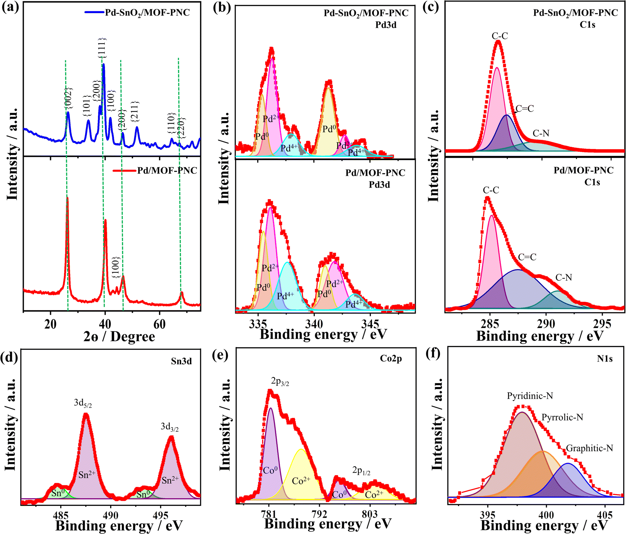 | ||
| Fig. 2 (a) XRD, and high-resolution XPS (b) Pd 3d, (c) C 1s (d) Sn 3d, (e) Co 2p and (f) N 1s of Pd–SnO2/MOF-PNC and Pd/MOF-PNC. The green lines in (a) refer to the positions of pure Pd NPs on C, which were taken from the JCPDS database. | ||
The XPS survey of the catalysts displays the valence state of Pd 3d/Co 2p/C 1s/O 1s/N 1s, but Pd–SnO2/MOF-PNC showed additional spectra of Sn 3d (Fig. S3b, ESI†). The atomic contents of Pd (2.16 at%) in Pd–SnO2/MOF-PNC and 2.71 at% in Pd/MOF-PNC imply the coherent distribution of Pd on the surface, but the bulk metal contents are given by the ICP-OES (Table S1, ESI†), which is critical for providing enough active sites for thermal COOxid. Pd 3d spectra of Pd–SnO2/MOF-PNC and Pd/MOF-PNC display the phases of Pd0, Pd2+, and Pd4+ (Fig. 2b).35 The ratio of Pd0 to Pd2+ in Pd–SnO2/MOF-PNC (0.62) was lower than Pd/MOF-PNC (0.77), due to the incorporation of metal oxide (i.e., SnO2) signifying more Pd2+ in the Pd–SnO2/MOF-PNC.35
The Pd–SnO2/MOF-PNC had a higher ratio of Pd2+ than Pd/MOF-PNC, owing to its possible interaction with SnO2 during the reduction process, which led to the partial oxidation of Pd to generate more active PdOx species and slightly decreased the d-band center of Pd, evidenced by the slight positive shift of Pd binding energies of Pd–SnO2/MOF-PNC than Pd/MOF-PNC (Table S2, ESI†). Norskov et al. suggested that a d-band center and d-bandwidth slightly below the Fermi level is optimal for CO chemisorption, so the reduced d-band center of Pd may allow strong interaction and possible poisoning and deactivation.37,38 However, this did not happen in the case of Pd–SnO2/MOF-PNC, due to the promotional effect of Pd0/Pd–Ox and their interfacial interaction with SnO2 and Co/N-doped porous MOF-derived C. Notably, Norskov and co-workers reported the ability of promoters to balance the CO chemisorption on the metal surface and enhance its activity.37,38 The C 1s spectra are assigned to sp3/sp2 (C–C/C![[double bond, length as m-dash]](https://www.rsc.org/images/entities/char_e001.gif) C) and the C–N bond (Fig. 2c), but shifted positively in Pd–SnO2/MOF-PNC than Pd/MOF-PNC, due to the reduced electron density on C by the interaction with Pd–SnO2. The Sn 3d spectra display major Sn2+ (3d5/2 and 3d3/2) and minor Sn0 (Fig. 2d). Meanwhile, Co 2p spectra show Co2+ (3d3/2 and 3d1/2) and Co0 (Fig. 2e). The N 1s spectra are attributed to pyridinic, pyrrolic, and graphitic (Fig. 2f).
C) and the C–N bond (Fig. 2c), but shifted positively in Pd–SnO2/MOF-PNC than Pd/MOF-PNC, due to the reduced electron density on C by the interaction with Pd–SnO2. The Sn 3d spectra display major Sn2+ (3d5/2 and 3d3/2) and minor Sn0 (Fig. 2d). Meanwhile, Co 2p spectra show Co2+ (3d3/2 and 3d1/2) and Co0 (Fig. 2e). The N 1s spectra are attributed to pyridinic, pyrrolic, and graphitic (Fig. 2f).
The BET-specific surface area of Pd–SnO2/MOF-PNC (185.40 m2 g−1) is slightly higher than that of Pd/MOF-PNC (152.83 m2 g−1), and Pd/C (107.91 m2 g−1) (Fig. S5a–c, ESI†); meanwhile, the pore volume of Pd–SnO2/MOF-PNC (0.045 cm3 g−1) was slightly higher than that of Pd/MOF-PNC (0.030 cm3 g−1), and Pd/C (0.012 m3 g−1), in addition to their multiple pore size range (2–110 nm) with mean pore sizes of 66.78, 56.54, and 12.31 nm for Pd–SnO2/MOF-PNC, Pd/MOF-PNC, and Pd/C, respectively (Fig. S5d–f, ESI†).
The thermal COOxid shows typical light-off curves for the conversion of CO to CO2 at heating temperatures (25–300 °C) and atmospheric pressure, but a superior activity on Pd–SnO2/MOF-PNC than Pd/MOF-PNC, and Pd/C (Fig. 3a).39,40 The T100 of Pd–SnO2/MOF-PNC (65.6 °C) is lower than that of Pd/MOF-PNC (107.9 °C) by 42.3 °C and Pd/C (201.2 °C) by 135.6 °C. This is due to the electronic and synergistic interaction of Pd0/Pd–Ox active sites with oxygen-enriched SnO2, Co–Nx and MOF-PNC, which optimizes CO + O2 adsorption/activation and desorption of CO2 at low temperatures.
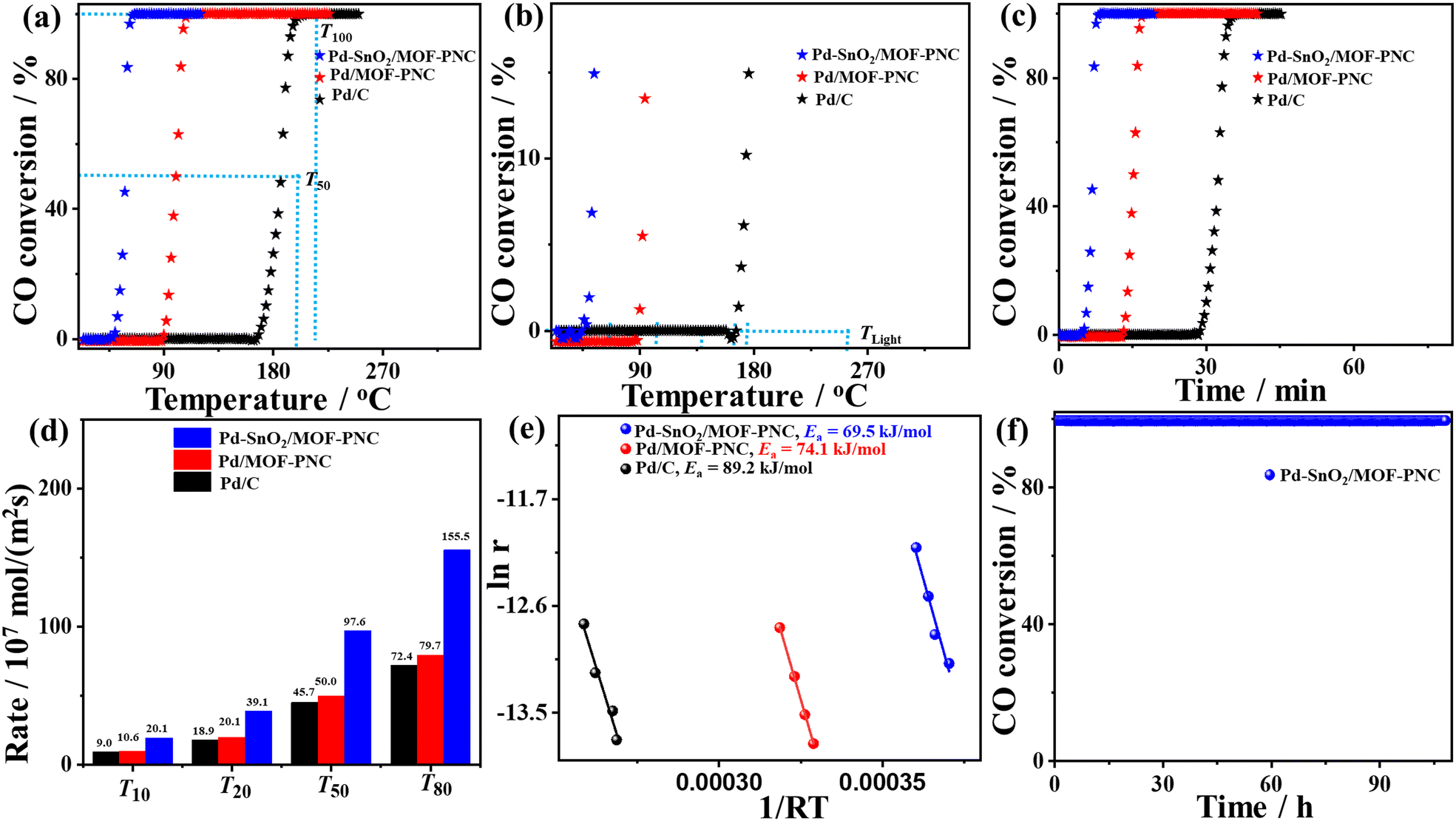 | ||
| Fig. 3 (a, b) Temperature-dependent CO conversion, (c) time-dependent CO conversion, (d) rate at different CO conversion temperatures, (e) Arrhenius plots, and (f) time on stream (TOS) of Pd–SnO2/MOF-PNC, Pd/MOF-PNC, and Pd/C. | ||
Thus, Pd–SnO2/MOF-PNC has higher COOxid kinetics than Pd/MOF-PNC, and Pd/C, owing to its capacity to oxidize CO at all applied temperatures (Fig. 3b), i.e., 50% of CO to CO2 (T50 = 58.4 °C) on Pd–SnO2/MOF-PNC was lower than Pd/MOF-PNC (99.9 °C) and Pd/C (186 °C). So, Pd–SnO2/MOF-PNC completely oxidizes CO within only 13.12 min compared to Pd/MOF-PNC (21.58 min) and Pd/C (40.24 min) (Fig. 3c). The COOxid activity of Pd–SnO2/MOF-PNC was superior to previously reported Pd-based catalysts, i.e., Pd/CeSn, Pd@SiO2/TiO2, Pd@CeO2, Pd/MgO, (Pd@SiO2-673-CeO2 (92 °C),21 Pd/MgO-h-BN (140 °C),20 Cu/Cu2O-500 nanojunctions (155 °C),31 Pd/Cu/gC3N4NTs (154 °C),41 Pd-Cu/gC3N4NWs (149 °C),42 and Au/Pd/gC3N4NFs (149 °C)43) (Table S3, ESI†). The T100 of Pd–SnO2/MOF-PNC (65.6 °C) is among the lowest values reported for Pd-based catalysts as far as we found. The COOxid rate (rCO) of Pd–SnO2/MOF-PNC was 1.95 and 2.15 times that of Pd/MOF-PNC and Pd/C, respectively (Fig. 3d), indicating maximum utilization of Pd active sites in Pd–SnO2/MOF-PNC, due to its greater porosity, which makes Pd active sites more accessible during COOxid.
This is further seen in the lower activation energy (Ea = 69.5 kJ mol−1) of Pd–SnO2/MOF-PNC than Pd/MOF-PNC (74.1 kJ mol−1) and Pd/C (89.2 kJ mol−1) (Fig. 3e). The COOxid stability of Pd–SnO2/MOF-PNC at 65.6 °C was shown by a time-on-stream (TOS) for 108 h (Fig. 3f), which reveals excellent durability with insignificant loss in T100. The stability of Pd–SnO2/MOF-PNC is further provided by TEM, which displayed the good dispersion of Pd nanoparticles over SnO2/MOF-PNC without any obvious aggregation, indicating the architecture durability (Fig. S6a, ESI†). The XPS full-scan showed the presence of C 1s, Pd 3d, Co 2p, O 1s, N 1s, and Sn 3d without significant degradation for Pd (2.13 at%), implying compositional stability (Fig. S6b, ESI†). The BET maintained the same isotherm adsorption/desorption features before stability with an inferior loss in the surface area and pore volume (Fig. S6c and d, ESI†). This implies the reservation of the physiochemical properties of Pd–SnO2/MOF-PNC after the durability test, as also proved by measuring the COOxid after the stability test, which displayed a minimal loss in the T100 (only 5 °C) (Fig. S4b, ESI†).
The active sites and CO2 production rate of Pd–SnO2/MOF-PNC are proved by its higher turnover number (TON = 14.8 μmol gCat−1) and turnover frequency (TOF = 61.97 h−1) relative to Pd/MOF-PNC (11.5 μmol gCat−1; 45.75 h−1) and Pd/C (7.86 μmol gCat−1; 31.49 h−1) (Fig. 4a and b). The recyclability of Pd–SnO2/MOF-PNC reveals that the catalyst remained active for 5 consecutive cycles with no degradation. The CO-TPD gave sharp peaks for Pd–SnO2/MOF-PNC (74.5 °C) and Pd/MOF-PNC (72.6 °C), compared to a broad peak for Pd/C (174.2 °C) (Fig. 5a). This implies more accessible Pd active sites in Pd–SnO2/MOF-PNC and its capacity to adsorb/oxidize CO at a lower temperature due to the presence of an oxygen-rich SnO2 support, higher surface area, and abundant active sites.36
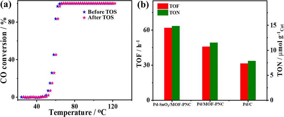 | ||
| Fig. 4 (a) Temperature of CO conversion before and after the TOS test and repetitive CO conversion after H2-TPR and O2-TPO of Pd–SnO2/MOF-PNC. (b) Turnover number (TON) and turnover frequency (TOF) of Pd–SnO2/MOF-PNC, Pd/MOF-PNC and Pd/C. | ||
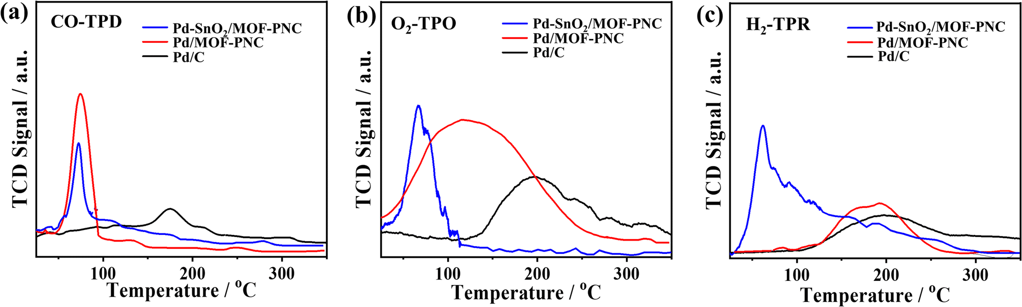 | ||
| Fig. 5 (a) CO-temperature-programmed desorption (CO-TPD), (b) O2-temperature-programmed oxidation (O2-TPO), and (c) H2-temperature-programmed reduction (H2-TPR) of Pd–SnO2/MOF-PNC, Pd/MOF-PNC and Pd/C. | ||
The O2-TPO displays a sharp oxygen-uptake peak on Pd–SnO2/MOF-PNC (66.8 °C) relative to broad peaks on Pd/MOF-PNC (116.3 °C) and Pd/C (197.6 °C) (Fig. 5b), implying ease of O2 adsorption (Oads) on Pd–SnO2/MOF-PNC, due to the interfacial interaction of Pd with SnO2 and MOF-PNC. This leads to rapid turnover of the adsorbed CO/O2, which is important for inducing a reaction between the active Oads and COad on the Pd surface to allow quick COOxid kinetics.36 Also, the oxygenated species (i.e., SnO2) in Pd–SnO2/MOF-PNC enables a lower energy barrier for CO/O2 uptake/activation, thereby accelerating the complete COOxid kinetics.24,33 The H2-TPR confirms the reducibility of the catalysts,36 where Pd–SnO2/MOF-PNC, Pd/MOF-PNC, and Pd/C show a broad H2 adsorption at 62.3, 184.1, and 199.9 °C, respectively, which implies that Pd–SnO2/MOF-PNC got reduced fast, owing to the interaction of SnO2, Pd2+, and Co2+ (Fig. 5c). This may serve as evidence for its exposed metal active sites.
The H2-TPR, O2-TPO, and CO-TPD reveal that coupled Pd, SnO2, and MOF-PNC enhance the CO redox properties and COOxid activity of Pd–SnO2/MOF-PNC. Hence, the COOxid mechanism on Pd–SnO2/MOF-PNC could follow Langmuir–Hinshelwood,36i.e., co-adsorption of CO/O2 on Pd–SnO2/MOF-PNC, followed by dissociation of O2 to form O lattice and O adsorbed (Oads) (eqn (R1) and (R2)), which then oxidizes COads to CO2ads (i.e., the rate determining step (eqn (R3))) and CO2 desorbed from Pd–SnO2/MOF-PNC (eqn (R4)).
| O2g + Pd–SnO2/MOF-PNC → 2Oads–Pd–SnO2/MOF-PNC | (R1) |
| COg + Pd–SnO2/MOF-PNC → COads–Pd–SnO2/MOF-PNC | (R2) |
| Oads–Pd–SnO2/MOF-PNC + COads–Pd–SnO2/MOF-PNC → CO2ads–Pd–SnO2/MOF-PNC | (R3) |
| CO2ads–Pd–SnO2/MOF-PNC → CO2 + Pd–SnO2/MOF-PNC | (R4) |
To investigate the effect of Pd nanoparticles loaded with a lower content (i.e., 1 wt%) decorated on SnO2/MOF-PNC, Pd(1%)–SnO2/MOF-PNC was prepared and tested for thermal CO oxidation, which showed significantly higher T100 (165.2 °C) than Pd–SnO2/MOF-PNC (65.6 °C) (Fig. S7a, ESI†). Meanwhile, in the absence of Pd nanoparticles, SnO2/MOF-PNC could not attain T100 even at 300 °C, implying that Pd is the main active site for the thermal CO oxidation. Also, to get more insights into the effect of the support, Pd–SnO2 was examined for COOxid and achieved T100 (199.1 °C) which was greater than Pd–SnO2/MOF-PNC (65.6 °C) and even Pd/MOF-PNC (107.9 °C) (Fig. S7a–c, ESI†), which indicates that using a co-support of SnO2/MOF-PNC is crucial for promoting the COOxid activity and kinetics as further seen in the lower rate (rCO) of Pd–SnO2 than that of Pd–SnO2/MOF-PNC, and Pd(1%)–SnO2/MOF-PNC (Fig. S7d, ESI†). Also, the estimated Ea of Pd–SnO2 was greater than that of Pd(1%)–SnO2/MOF-PNC, Pd/MOF-PNC, and Pd–SnO2/MOF-PNC (Fig. S7e, ESI†). These results clarify the importance of combining mixed Pd phases (Pd0/Pd–Ox) and an oxygen-rich SnO2 support for excellent COOxid activity as shown by low T100, but high kinetics, TON and TOF of Pd–SnO2/MOF-PNC. Thus, coupling Pd with a metal oxide support is preferred for promoting the COOxid, due to the optimal CO/O2 adsorption and ease of activation/dissociation at low temperatures.
Conclusion
In brief, hierarchical porous sponge-like Pd–SnO2/MOF-PNC was prepared by the MW-I, annealing, and chemical etching approach to initially form MOF-PNC, mixed with SnO2 and Pd and then MW-I. Pd–SnO2/MOF-PNC comprises porous 2D ultrathin MOF-PNC NSs with monodispersed Pd–SnO2 NPs (7.79 ± 1.42 nm), a large specific surface area (185.40 m2 g−1), and pore volume (0.045 cm3 g−1). Thus, the COOxid at T100 of Pd–SnO2/MOF-PNC (65.6 °C) was lower than those of Pd/MOF-PNC (107.9 °C), Pd(1%)–SnO2/MOF-PNC (165.2 °C), Pd–SnO2 (199.1 °C), and Pd/C (201.2 °C), and also superior to most previously reported Pd-based catalysts. This originated from the electronic interaction and synergism of Pd NPs with oxygen-rich SnO2 supports and Co-Nx active sites in MOF-PNC to deliver low energy barriers and high kinetics. These results indicate that using two supports, SnO2/MOF-PNC is preferred for promoting the thermal COOxid activity of Pd NPs.Conflicts of interest
We declare no conflicts of interest.Acknowledgements
This work was supported by the Qatar University High Impact Internal Grant (QUHI-CAM-22/23-550) and the DSI-NRF-Wits SARChI Chair in Materials Electrochemistry and Energy Technologies (MEET) (UID No.132739).References
- K. Eid, Q. Lu, S. Abdel-Azeim, A. Soliman, A. M. Abdullah, A. M. Abdelgwad, R. P. Forbes, K. I. Ozoemena, R. S. Varma and M. F. Shibl, J. Mater. Chem. A, 2022, 10, 1965–1975 RSC.
- K. Liu, P. Cao, W. Chen, C. I. Ezeh, Z. Chen, Y. Luo, Q. Liu, H. Zhao, Z. Rui and S. Gao, Mater. Adv., 2022, 3, 1359–1400 RSC.
- B. Salah, A. Abdelgawad, Q. Lu, A. K. Ipadeola, R. Luque and K. Eid, Green Chem., 2023, 25, 6032–6040 RSC.
- K. Timmo, M. Pilvet, K. Muska, M. Altosaar, V. Mikli, R. Kaupmees, R. Josepson, J. Krustok, M. Grossberg-Kuusk and M. Kauk-Kuusik, Mater. Adv., 2023, 4, 4509–4519 RSC.
- J. Saengkaew, T. Kameda and S. Matsuda, Mater. Adv., 2023, 4, 4417–4424 RSC.
- Q. Lu, J. Li, K. Eid, X. Gu, Z. Wan, W. Li, R. S. Al-Hajri and A. M. Abdullah, J. Electroanal. Chem., 2022, 916, 116361 CrossRef CAS.
- P. Aggarwal, B. Singh and A. Paul, Mater. Adv., 2023, 4, 4377–4389 RSC.
- K. Eid, A. Gamal and A. M. Abdullah, Green Chem., 2023, 25, 1276–1310 RSC.
- S. Ghosh, A. Modak, A. Samanta, K. Kole and S. Jana, Mater. Adv., 2021, 2, 3161–3187 RSC.
- J. Marti-Rujas, Mater. Adv., 2023, 4, 4333–4343 RSC.
- K. Eid, Y. H. Ahmad, H. Yu, Y. Li, X. Li, S. Y. AlQaradawi, H. Wang and L. Wang, Nanoscale, 2017, 9, 18881–18889 RSC.
- A. K. Ipadeola, A. B. Haruna, A. M. Abdullah, M. F. Shibl, D. Ahmadalie, K. I. Ozoemena and K. Eid, Catal. Today, 2023, 114178 CrossRef CAS.
- Y. A. May, S. Wei, W.-Z. Yu, W.-W. Wang and C.-J. Jia, Langmuir, 2020, 36, 11196–11206 CrossRef CAS PubMed.
- Q. Xiao, S. Wei, W.-W. Wang and C.-J. Jia, Langmuir, 2021, 37, 3270–3280 CrossRef CAS PubMed.
- C. Miao, L. Zhang, W. Xie, L. Liang, S. Chen, Y. Zhang and J. Ouyang, Mater. Adv., 2022, 3, 232–244 RSC.
- B. Szczęśniak, J. Choma and M. Jaroniec, Mater. Adv., 2021, 2, 2510–2523 RSC.
- X. Chen, L. P. Granda-Marulanda, I. T. McCrum and M. Koper, Nat. Commun., 2022, 13, 1–11 CAS.
- C. R. Zanata, A. C. Gaiotti, L. R. Sandim, C. A. Martins, L. M. Pinto, M. J. Giz and G. A. Camara, J. Electroanal. Chem., 2021, 886, 115149 CrossRef CAS.
- H. Ahmad and M. K. Hossain, Mater. Adv., 2022, 3, 859–887 RSC.
- L. Li, X. Liu, H. He, N. Zhang, Z. Liu and G. Zhang, Catal. Today, 2019, 332, 214–221 CrossRef CAS.
- Y. Xu, J. Ma, Y. Xu, L. Xu, L. Xu, H. Li and H. Li, RSC Adv., 2013, 3, 851–858 RSC.
- Y. Aoyama, H. Kobayashi, T. Yamamoto, T. Toriyama, S. Matsumura, M. Haneda and H. Kitagawa, Chem. Commun., 2020, 56, 3839–3842 RSC.
- A. K. Ipadeola, A. Gamal, A. M. Abdullah, A. B. Haruna, K. I. Ozoemena and K. Eid, Catal. Sci. Technol., 2023, 13, 4873–4882 RSC.
- A. K. Ipadeola, K. Eid, A. M. Abdullah and K. I. Ozoemena, Langmuir, 2022, 38, 11109–11120 CrossRef CAS PubMed.
- Y. Xue, G. Zhao, R. Yang, F. Chu, J. Chen, L. Wang and X. Huang, Nanoscale, 2021, 13, 3911–3936 RSC.
- J. Liu, T. A. Goetjen, Q. Wang, J. G. Knapp, M. C. Wasson, Y. Yang, Z. H. Syed, M. Delferro, J. M. Notestein and O. K. Farha, Chem. Soc. Rev., 2022, 51, 1045–1097 RSC.
- M. Sadakiyo, Nanoscale, 2022, 14, 3398–3406 RSC.
- Q. Liang, Z. Zhao, J. Liu, Y.-C. Wei, G.-Y. Jiang and A.-J. Duan, Acta Phys.-Chim. Sin., 2014, 30, 129–134 CAS.
- Y. Hu, X. Song, Q. Zheng, J. Wang and J. Pei, RSC Adv., 2019, 9, 9962–9967 RSC.
- G. Zhong, D. Liu and J. Zhang, J. Mater. Chem. A, 2018, 6, 1887–1899 RSC.
- R. Zhang, L. Hu, S. Bao, R. Li, L. Gao, R. Li and Q. Chen, J. Mater. Chem. A, 2016, 4, 8412–8420 RSC.
- M. Hao, M. Qiu, H. Yang, B. Hu and X. Wang, Sci. Total Environ., 2021, 760, 143333 CrossRef CAS PubMed.
- A. K. Ipadeola, K. Eid, A. M. Abdullah, R. S. Al-Hajri and K. I. Ozoemena, Nanoscale Adv., 2022, 4, 5044–5055 RSC.
- X. Wang, W. Zhong and Y. Li, Catal. Sci. Technol., 2015, 5, 1014–1020 RSC.
- A. K. Ipadeola, P. V. Mwonga, S. C. Ray, R. R. Maphanga and K. I. Ozoemena, ChemElectroChem, 2020, 7, 4562–4571 CrossRef CAS.
- K. Eid, M. H. Sliem, M. Al-Ejji, A. M. Abdullah, M. Harfouche and R. S. Varma, ACS Appl. Mater. Interfaces, 2022, 14, 40749–40760 CrossRef CAS PubMed.
- B. Hammer, O. H. Nielsen and J. Nrskov, Catal. Lett., 1997, 46, 31–35 CrossRef CAS.
- B. Hammer, Y. Morikawa and J. K. Nørskov, Phys. Rev. Lett., 1996, 76, 2141 CrossRef CAS PubMed.
- Y. Fang, X. Chi, L. Li, J. Yang, S. Liu, X. Lu, W. Xiao, L. Wang, Z. Luo and W. Yang, ACS Appl. Mater. Interfaces, 2020, 12, 7091–7101 CrossRef CAS PubMed.
- W. Li, Q. Ge, X. Ma, Y. Chen, M. Zhu, H. Xu and R. Jin, Nanoscale, 2016, 8, 2378–2385 RSC.
- K. Eid, M. H. Sliem, K. Jlassi, A. S. Eldesoky, G. G. Abdo, S. Y. Al-Qaradawi, M. A. Sharaf, A. M. Abdullah and A. A. Elzatahry, Inorg. Chem. Commun., 2019, 107, 107460 CrossRef CAS.
- K. Eid, Y. H. Ahmad, A. T. Mohamed, A. G. Elsafy and S. Y. Al-Qaradawi, Catalysts, 2018, 8, 411 CrossRef.
- K. Eid, M. H. Sliem, A. S. Eldesoky, H. Al-Kandari and A. M. Abdullah, Int. J. Hydrogen Energy, 2019, 44, 17943–17953 CrossRef CAS.
Footnote |
| † Electronic supplementary information (ESI) available. See DOI: https://doi.org/10.1039/d3ma00819c |
| This journal is © The Royal Society of Chemistry 2024 |