
 Open Access Article
 This Open Access Article is licensed under a Creative Commons Attribution-Non Commercial 3.0 Unported Licence
Upstream mobility and swarming of light activated micromotors†
Bingzhi
Wu
,
David P.
Rivas
and
Sambeeta
Das
*
Department of Mechanical Engineering, University of Delaware, 210 South College Ave, Newark, DE 19716, USA. E-mail: samdas@udel.edu
First published on 26th October 2023
Abstract
Micromotors have been proposed for applications such as targeted drug delivery, thrombolysis, or sensing. However, single micrormotors are limited in the amount of payload they can deliver or force they can exert. Swarms of micromotors can overcome many of these challenges, however creating and controlling such swarms presents many challenges of its own. In particular, utilizing swarms in fluid flows is of significant importance for biomedical or lab-on-chip applications. Here, the upstream mobility and swarm formation of light driven micromotors in microchannel flows is demonstrated with maximum speeds around 0.1 mm s−1. Additionally, the light actuated microrobots operate in fairly low concentrations of hydrogen peroxide of approximately 1%. The micromotors form swarms at the boundary of the locally applied light pattern and the swarms can be moved by translating the light up or downstream.
1 Introduction
The unique advantages offered by the controlled navigation of active particles provides tantalizing possibilities for their use in lab-on-chip or biomedical applications. For example, active microrobots could be used for cell sorting, manipulation, or drug delivery.1–3 For example, as a proof on concept, micron-sized particles have been loaded with a cancer killing agent, doxorubicin, and magnetically manipulated to cancer cells in vitro.4,5 Other microrobots have been used to deliver signaling molecules which were released on demand with light activation.6 Micromotor swarms, in particular, are promising candidates for biomedical applications due to their enhanced capabilities compared to that of a single particle.7–10 For example, a swarm of micromotors can deliver a higher payload, be easier to image, and provide more power than an individual micromotor. Swarms of particles have been generated using magnetic fields,8,9,11 chemical effects,12,13 electric fields,14,15 thermal gradients,16 and acoustic waves.17–20 Swarm-like schools of light-active particles have also been formed21 as well as self-attractive clusters,22–24 although control of such collections of light-active units in flows has not yet been demonstrated.In order for the full capabilities of navigation in microfluidic chips or in blood flows to be accomplished, it is necessary to move the micromotors against fluid flows. There has been some success with magnetically controlled particles,25,26 bubble-propelled active motors,27 and acoustic-magnetic28 micromotors in moving against flows similar to those in blood vessels. In addition, magnetically powered microrobots have been driven in vivo29 as well. Self-phoretically driven chemically active micromotors, which are propelled by using a chemical in the fluid as a fuel source, have also shown the ability to move against flow.30–32 For example, in Palacci et al.30 the micromotors exhibited rheotaxis, an alignment of the micromotor swimmer such that its direction of propagation points upstream, and these micromotors were able to move against modest flows of ∼10 μm s−1. In Baker et al., Au–Pt microrods also moved upstream against fast flows of up to a few centimeters per second with a hydrogen peroxide concentration of 30%. A significant disadvantage of most chemically active micromotors is that the fuel they require is typically toxic and therefore cannot be used in high concentrations. Light actuated micromotors have an advantage in this regard due to their ability to attain relatively high speeds with low, or even non-existent, chemical concentrations.33 Light active micromotors also have an advantage of being more easily selectively actuated compared to magnetically driven particles which typically rely on fields that apply forces or torques to all of the particles at once.34
Here we show the swarm formation and upstream mobility of light-activated micromotors against fluid flows in microchannels. The maximum flow speeds were approximately 100 μm s−1. The micromotors also require a relatively low concentration of hydrogen peroxide fuel of around 1%. In addition to individual upstream motility of the motors, by applying a localized region of light, a swarm of motors formed at the upstream boundary of the light. The swarm's position can be translated upstream or downstream in the channel by a relative positioning of the light in the upstream or downstream direction, respectively. Moving the light downstream of the micromotors results in their flow downstream until they reach the light boundary where they again attain dynamic equilibrium against the flow. Moving the light upstream of the micromotors provides them with an increase in propulsive speed which causes them to move upstream towards the new position of the light boundary. We believe this work provides an important step towards the navigation of light-driven micromotor swarms in relatively fast flows, and hence their utilization in biomedical, lab-on-chip, or other applications.
2 Experimental
Details of the micromotor synthesis and other experimental procedures can be found in the supporting information. Briefly, the motors were coated in Ni/Fe alloy at a glancing angle followed by Pt and then Ag layers by electron-beam evaporation. The Ni/Fe layer made the motors magnetically responsive while the Pt and Ag layers were added to improve their light-induced activity. The magnetic layer was deposited at a glancing angle to increase the contact between the Pt coating and the TiO2 surface. Previous studies have shown the relative effectiveness of using Pt compared to other metals on the speed of TiO2 micromotors,35 and additional work has shown that a bimetallic coating can be advantages as well.36 Using an outer Ag layer rather than Pt also reduces the catalytic decomposition of hydrogen peroxide which mitigates the problem of oxygen bubble formation in the channels. We provide a plot of the micromotor speed in various levels of hydrogen peroxide concentrations and at a range of light intensities in the supporting information. The PDMS microchannels were made using standard photolithography techniques and have a width of 35 μm and a height of 16 μm.A digital micromirror device (DMD) was used as the UV light source (MIGHTEX Polygon 1000 Pattern Illuminator), which produces UV light at 365 nm and an intensity of around 500 mW cm−2. A schematic of the experimental setup is shown in Fig. 1(a).
 | ||
| Fig. 1 (A) Schematic of the experimental system. A microfludic pump is used to fill the channels with the micromotors and their motion is observed through a microscope. (B) A DMD light source illuminates a rectangular region of the microchannel with UV light, causing the TiO2 micromotors to become motile. | ||
3 Results and discussion
Light-actuated micromotors absorb energy from a light source to generate motility. This is typically done with the use of metal coated Janus semiconductor-based motors which self-propel by a self-electrophoretic mechanism.33 The excitation of electrons into the conduction band results in the flow of charge toward the metal coating on the micromotor.37 An anisotropic electric charge distribution develops around the motors resulting in a self-electrophoretic force that drives the motors.In the absence of UV light, the micromotors are advected with the fluid flow. Thus we were able to determine the fluid flow speed by using these micromotors as tracers. Application of a localized rectangular region of UV light to the channel, as shown in Fig. 1(b), resulted in active propulsion of the motors.
Once the light is applied, we find that a subset of the active motors immediately stop flowing downstream and begin to self-propel upstream (see video S1, ESI†). Although some micromotors move directly upstream, occasionally the motors first move towards the edges of the channel before either stopping or moving along the edge and further upstream. Generally, without flow, these micromotors undergo curved trajectories due to an active torque caused by imperfections in their shape. A magnetic field acts to make the trajectories of these micromotors more linear due to a suppression of their natural active rotation.24 Therefore, we applied a magnetic field by placing a permenant magnet near the sample, resulting in less rotation of the micromotors and more persistent motility upstream.
The micromotors continued to move upstream until they reached the edge of the light where they remained in a dynamic equilibrium. Once at the edge of the light, their position tends to fluctuate in the upstream and downstream directions (see video S2, ESI†). This dynamic steady-state can be understood by a balance of active propulsion upstream and a passive flow downstream. As they move somewhat more upstream and away from the light source, their decrease in active propulsion results in a movement with the flow downstream. Likewise, as they move downstream and enter the illuminated region, they attain sufficient propulsion speed to move against the flow again.
The flow of micromotors into the illuminated region continuously resulted in more and more micromotors that were capable of moving against the flow. Therefore, over time a swarm of motors gathered at the upstream edge of the light, as shown in Fig. 2 and video S2 (ESI†). We observed that over a period of about 10 minutes, a swarm of around 35 micromotors formed. We estimate this to be approximately 1–2% of the total number of micromotors that passed through the illuminated region during that time period. The difference in positioning of the micromotors at the edge of the light indicates a variability in their activity level, i.e., those that are somewhat more upstream likely have a higher activity level than those that are positioned farther downstream in the swarm.
 | ||
| Fig. 2 (A) A sketch showing how the swarm gathers at the light boundary. (B) An image of a swarm of micromotors in dynamic equilibrium within a left to right maximum flow rate of around 100 μm s−1. | ||
In the example shown in Fig. 2, we found that in the absence of light, the majority of the micromotors are advected with the flow with speeds around 32 μm s−1 while some move at much higher speeds of around 100 μm s−1, indicating that most of the micromotors reside near the floor of the channel rather than in the central region where the flow rate is highest, presumably due to sedimentation.
To determine how many motors are expected to have sufficient speed to move against the fluid flow, we measured the distribution of velocities of the motors after the flow had stopped. The results are shown in Fig. 3 (see also video S4, ESI†). The typical speed of the motors was around 10 μm s−1 which is much less than the maximum flow speed of approximately 100 μm s−1. This difference is likely due to two reasons: firstly, only a small percentage (around 1%) of the motors are able to move upstream, therefore this subset may consist only of the most active motors. Secondly, the motors that are able to move upstream may reside near the bottom of the channel where there is a slower flow rate.
 | ||
| Fig. 3 A histogram of the micromotor speeds with light applied in the absence of flow. | ||
To explore this further, we analyzed the velocity of the upstream-moving motors once the light was turned off and the micromotors began to be advected with the flow. We found that in a time period of around a second after the light was turned off, these micromotors moved at an average speed of 35 μm s−1, indicating that the actual flow speed that they were swimming against while moving upstream was less than the maximum flow speed of the channel of 100 μm s−1. Occasionally, the micromotors would later be advected at higher speeds similar to that of the maximum flow speed of the channel (see video S6, ESI†). This implies, therefore, that while they were illuminated they remained in close proximity to the floor of the channel where the flow rate was lower and soon after the light was turned off they were swept into the bulk flow. One explanation of this is that the light acts not only to propel the micromotors upstream, but also to create an attractive force that acts to maintain a close proximity to the channel floor. Chemical attraction to the substrate could be the result of a phoretic effect, as has been observed previously.38
It was possible to control the position of the swarm by moving the region illuminated by light upstream or downstream, as shown in Fig. 4 and video S3 (ESI†). The micromotors in the swarm continued to move upstream until they reached the boundary of the light, or, if the light was moved downstream, would flow downstream until they were again at the light boundary.
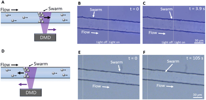 | ||
| Fig. 4 (A) A sketch showing how the moving the light downstream results in a translation of the swarm downstream. (B) An image of a swarm of micromotors after the light had been moved downstream. (C) An image 3.9 seconds later of the swarm which repositioned itself at the light boundary. (D) A sketch showing the swarm following the upstream movement of the light. (E) An image of the channel immediately after moving the light upstream of the swarm. (F) An image 105 seconds later showing the movement of the swarm upstream towards the new position of the light. The vertical line represents the light boundary (to the right of the line is where the light was applied). | ||
We measured the velocity profile of the fluid within the channel by measuring the velocity of passive micromotors as a function of distance from the channel walls without applied light. The result of one of these measurements as a function of distance from the edges of the channel is shown in Fig. S1 (ESI†). The velocity profile is greatest in the middle of the channel and decreases at the edges, approximately following a parabolic shape. Therefore, one might expect that the trajectories of the micromotors curve upstream as they approach the walls of the channel due to the decrease in flow velocity, hence effectively increasing the component of the micromotors velocity in the upstream direction. However, in general this is not observed to be the case. Although some motors did move upstream as they approached the walls of the channels, others moved downstream or showed little to no alteration of their trajectory as they approached the edges. We attribute this to either the natural tendency for many of these active motors to undergo somewhat curved trajectories, hence complicating the effects of the flow on their motion, as well as the nearness of the micromotors to the channel floor and walls along with possible attractive interactions which could additionally complicate their trajectories.
In the absence of flow, the micromotors move towards and collide with the edges of the channel (see video S4, ESI†). Initially, the micromotors propel linearly in the channel until reaching the walls. Once in contact with the walls, they remain in close contact while the light is on. Although an attractive interaction could be one reason for them maintaining such a close proximity, another contribution could be due to an active force pushing the particle towards the wall. For example, theoretical modeling has predicted the accumulation of active motors near channel boundaries at sufficiently high Péclet number.39,40 With flow, many micromotors accumulate at the walls of the channel. Although the channel edge obscures most of them from view, once the light is turned off, they leave the walls and flow downstream (see video S5, ESI†).
With a magnetic field applied, the micromotors move in a wide range of directions rather than along the direction of the magnetic field. We have observed this previously24 and attribute it to differences in the magnetic coating on the micromotors or to the formation of aggregates which possess a magnetic moment that is misaligned with their direction of motion.
The application of a magnetic field acts to maintain a consistent direction of propagation of the micromotors which is important in attaining upstream motion and swarm formation. Reorientation of the micromotors would ultimately result in a direction of propagation downstream, hence the micromotor would not maintain its upstream motion for a sufficiently long time period to form a swarm of multiple micromotors. However, persistent upstream motion of micromotors without an external field is possible and has been observed previously.30–32 Such rheotaxis can be explained by a “weather vane” effect on anisotropic swimmers,41 for example, although it has also been observed with a spherical Janus micromotor recently.41 Although we were unable to investigate rheotaxis in these experiments due to the inability to observe the orientation of the micromotors, it would be interesting to explore this further in a future study.
4 Conclusions
In this work we demonstrated upstream motility of light-activated micromotors and swarm control in fairly low hydrogen peroxide concentration in microchannels with flow speeds up to about 0.1 mm s−1. Swarm formation occurred at the boundary of applied light and upstream or downstream positioning of the swarm was possible by corresponding movement of the light. We expect that the formation of the swarm at the light boundary could also be used as a means of particle separation to select the most active motors by trapping them at the edge of the illuminated region while less active ones pass by with the flow. Varying the flow rate or light intensity could therefore determine the cutoff of the level of activity of the separation. Although using light-active micromotors in the bloodstream would require overcoming additional challenges such as applying the UV light in potentially hard to reach and low-transparency regions, reducing the concentration of hydrogen peroxide to biocompatible levels, and overcoming obstacles such as cells, we believe these results demonstrate an important step towards such applications, namely the formation and movement of these swarms in fluid flows. Overall, the demonstrated use of light-active micromotor swarms in fluid flows is important to their use in lab-on-chip devices or possibly in future biomedical applications.Conflicts of interest
There are no conflicts to declare.Acknowledgements
This work was supported by the National Science Foundation under grant GCR 2219101 and the National Health Institute under grant 1R35GM147451. This project was also supported with a grant from the National Institute of General Medical Sciences - NIGMS (5P20GM109021-07) from the National Institutes of Health and the State of Delaware. This work is also supported by the University of Delaware GUR grant. Fig. 1A was created with BioRender.com.References
- M. Sitti, H. Ceylan, W. Hu, J. Giltinan, M. Turan, S. Yim and E. Diller, Proc. IEEE, 2015, 103, 205–224 CAS.
- R. Wu, Y. Zhu, X. Cai, S. Wu, L. Xu and T. Yu, Micromachines, 2022, 13, 1473 CrossRef PubMed.
- B. J. Nelson, I. K. Kaliakatsos and J. J. Abbott, Annu. Rev. Biomed. Eng., 2010, 12, 55–85 CrossRef CAS PubMed.
- K. T. Nguyen, G. Go, Z. Jin, B. A. Darmawan, A. Yoo, S. Kim, M. Nan, S. B. Lee, B. Kang, C.-S. Kim, H. Li, D. Bang, J.-O. Park and E. Choi, Adv. Healthcare Mater., 2021, 10, 2001681 CrossRef CAS.
- S. Mallick, R. Abouomar, D. Rivas, M. Sokolich, F. C. Kirmizitas, A. Dutta and S. Das, Adv. Healthcare Mater., 2023, e2300939 CrossRef.
- S. Das, E. E. Hunter, N. A. DeLateur, E. B. Steager, R. Weiss and V. Kumar, J. Micro-Bio Rob., 2019, 15, 79–90 CrossRef.
- L. Yang, J. Yu, S. Yang, B. Wang, B. J. Nelson and L. Zhang, IEEE Trans. Rob., 2022, 38, 1531–1551 Search PubMed.
- H. Xie, M. Sun, X. Fan, Z. Lin, W. Chen, L. Wang, L. Dong and Q. He, Sci. Rob., 2019, 4, eaav8006 CrossRef.
- Q. Wang and L. Zhang, ACS Nano, 2021, 15, 149–174 CrossRef CAS.
- Y. Fu, H. Yu, X. Zhang, P. Malgaretti, V. Kishore and W. Wang, Micromachines, 2022, 13, 295 CrossRef PubMed.
- J. Yu, D. Jin, K.-F. Chan, Q. Wang, K. Yuan and L. Zhang, Nat. Commun., 2019, 10, 5631 CrossRef CAS PubMed.
- W. Duan, R. Liu and A. Sen, J. Am. Chem. Soc., 2013, 135, 1280–1283 CrossRef CAS.
- D. Kagan, S. Balasubramanian and J. Wang, Angew. Chem., Int. Ed., 2011, 50, 503–506 CrossRef CAS PubMed.
- S.-R. Yeh, M. Seul and B. I. Shraiman, Nature, 1997, 386, 57–59 CrossRef CAS.
- J. Yan, M. Han, J. Zhang, C. Xu, E. Luijten and S. Granick, Nat. Mater., 2016, 15, 1095–1099 CrossRef CAS.
- Z. Deng, F. Mou, S. Tang, L. Xu, M. Luo and J. Guan, Appl. Mater. Today, 2018, 13, 45–53 CrossRef.
- J. Shi, D. Ahmed, X. Mao, S.-C. S. Lin, A. Lawit and T. J. Huang, Lab Chip, 2009, 9, 2890–2895 RSC.
- T. Xu, F. Soto, W. Gao, R. Dong, V. Garcia-Gradilla, E. Magaña, X. Zhang and J. Wang, J. Am. Chem. Soc., 2015, 137, 2163–2166 CrossRef CAS PubMed.
- J. Li, T. Li, T. Xu, M. Kiristi, W. Liu, Z. Wu and J. Wang, Nano Lett., 2015, 15, 4814–4821 CrossRef CAS.
- K. Melde, A. G. Mark, T. Qiu and P. Fischer, Nature, 2016, 537, 518–522 CrossRef CAS.
- M. Ibele, T. Mallouk and A. Sen, Angew. Chem., Int. Ed., 2009, 48, 3308–3312 CrossRef CAS PubMed.
- J. Palacci, S. Sacanna, A. P. Steinberg, D. J. Pine and P. M. Chaikin, Science, 2013, 339, 936–940 CrossRef CAS PubMed.
- D. P. Singh, U. Choudhury, P. Fischer and A. G. Mark, Adv. Mater., 2017, 29, 1701328 CrossRef.
- D. P. Rivas, M. Sokolich and S. Das, ChemNanoMat, 2023, e202300225 CrossRef CAS.
- Z. Wu, Y. Zhang, N. Ai, H. Chen, W. Ge and Q. Xu, Adv. Intell. Syst., 2022, 4, 2100266 CrossRef.
- Q. Wang, Y. Tian, X. Du, H. Ko, B. Y. M. Ip, T. W. H. Leung, S. C. H. Yu and L. Zhang, IEEE/ASME Trans. Mechatronics, 2022, 27, 3174–3185 Search PubMed.
- S. Sanchez, A. A. Solovev, S. M. Harazim and O. G. Schmidt, J. Am. Chem. Soc., 2011, 133, 701–703 CrossRef CAS PubMed.
- D. Ahmed, A. Sukhov, D. Hauri, D. Rodrigue, G. Maranta, J. Harting and B. J. Nelson, Nat. Machine Intell., 2021, 3, 116–124 CrossRef.
- Y. Alapan, U. Bozuyuk, P. Erkoc, A. C. Karacakol and M. Sitti, Sci. Rob., 2020, 5, eaba5726 CrossRef.
- J. Palacci, S. Sacanna, A. Abramian, J. Barral, K. Hanson, A. Y. Grosberg, D. J. Pine and P. M. Chaikin, Sci. Adv., 2015, 1, e1400214 CrossRef.
- R. Baker, J. E. Kauffman, A. Laskar, O. E. Shklyaev, M. Potomkin, L. Dominguez-Rubio, H. Shum, Y. Cruz-Rivera, I. S. Aranson, A. C. Balazs and A. Sen, Nanoscale, 2019, 11, 10944–10951 RSC.
- Q. Brosseau, F. B. Usabiaga, E. Lushi, Y. Wu, L. Ristroph, J. Zhang, M. Ward and M. J. Shelley, Phys. Rev. Lett., 2019, 123, 178004 CrossRef CAS PubMed.
- R. Dong, Q. Zhang, W. Gao, A. Pei and B. Ren, ACS Nano, 2016, 10, 839–844 CrossRef CAS.
- M. Wang, T. Wu, R. Liu, Z. Zhang and J. Liu, Engineering, 2023, 24, 21–38 CrossRef.
- T. Maric, M. Z. M. Nasir, R. D. Webster and M. Pumera, Adv. Funct. Mater., 2020, 30, 1908614 CrossRef CAS.
- Z. Xiao, J. Chen, S. Duan, X. Lv, J. Wang, X. Ma, J. Tang and W. Wang, Chem. Commun., 2020, 56, 4728–4731 RSC.
- S. Palagi, D. P. Singh and P. Fischer, Adv. Opt. Mater., 2019, 7, 1900370 CrossRef.
- J. Palacci, S. Sacanna, A. P. Steinberg, D. J. Pine and P. M. Chaikin, Science, 2013, 339, 936–940 CrossRef CAS PubMed.
- J. Elgeti and G. Gompper, Europhys. Lett., 2013, 101, 48003 CrossRef CAS.
- C. F. Lee, New J. Phys., 2013, 15, 055007 CrossRef.
- P. Sharan, Z. Xiao, V. Mancuso, W. E. Uspal and J. Simmchen, ACS Nano, 2022, 16, 4599–4608 CrossRef CAS.
Footnote |
| † Electronic supplementary information (ESI) available. See DOI: https://doi.org/10.1039/d3ma00814b |
| This journal is © The Royal Society of Chemistry 2024 |