 Open Access Article
Multifunctional and self-healable conductive IPN hydrogels functionalized with reduced magnetite graphene oxide for an advanced flexible all in one solid-state supercapacitor†
Tanzil ur
Rehman
,
Luqman Ali
Shah
 * and
Mansoor
Khan
Polymer Laboratory, National Centre of Excellence in Physical Chemistry, University of Peshawar, Peshawar 25120, Pakistan. E-mail: luqman_alisha@uop.edu.pk; luqman_alisha@yahoo.com; Fax: +92-91-9216671; Tel: +92-91-9216766
First published on 30th November 2023
Abstract
The all in one solid-state (AIOS) stretchable and flexible hydrogel electronic devices play a pivotal role in the development of elastic supercapacitors for energy storage and fast charging–discharging rates. However, poor ionic, electrochemical, electronic conductivity, self-healing ability, bioavailability, and weak mechanical stability have limited the use of such hydrogels in supercapacitors for real applications. In the present work, we report an interpenetrating network (IPN) of poly(vinyl alcohol) (PVA)-based green polymeric composite hydrogel, synthesized with a two-pot method. The first polymeric network consisted of guar gum (GG) which is used as a bio-template for the dispersant for the uniform distribution of sonicated reduced magnetite graphene oxide (rMGO) to produce rMGO-GG. This was blended with PVA and then physically crosslinked with borate ions to produce the IPN. The viscoelastic properties of the hydrogels were tested rheologically, and the storage modulus  was found to be 3.86 kPa within the linear viscoelastic region (LVR). The hydrogels exhibited an excellent healing potential which occurred in 5 to 10 s. The practical and self-assembled AIOS supercapacitor demonstrated a cyclic voltammetry capacitance of 85 F g−1, whereas the galvanostatic charge discharge (GCD) specific capacitance was 106.66 F g−1. The electrochemical impedance spectroscopy (EIS) of the materials also found an internal resistance of 1.22 Ω. The capacitance retention after 5000 cycles was 94.97%, demonstrating the cyclic stability of the hydrogels. The gauge factor (GF) was 8.25, with a conductivity of 0.89 S m−1 at 200% strain. The material was found to be efficient when applied as a practical device.
1. Introduction
Recent developments and progress in the field of hydrogels for their use in versatile applications in daily life make it more promising in general, and particularly in replacing traditional rigid wearable electronic devices.1 Hydrogels are used in many electrical devices such as smartphones,2 watches,3 sensors,4–6 and in flexible and healable electronic devices.7 Most of the existing traditional electronic energy storage devices have problems with mechanical wear and damage, and thus, wearing the electronic devices during their routine operation and application is not possible.8–10 In addition, most of these materials are environmentally threatening to the flora and fauna of the planet.11 In addition, most of the materials lose their ability for electrical conduction upon stretching and elongation. Therefore, to keep the cost low, and to ensure the recycling, bioavailability, biodegradability, biocompatibility, flexibility, safety, and self-healing abilities,12–14 one should keep it in mind these requirements before synthesizing electronic devices. Thus, in the recent world of energy harvesting and storage devices such as batteries and supercapacitors, they must have properties such as flexibility, stretchability, and a self-healing capability.15,16The modern supercapacitor achieves the application regarding their returns such as better and enhanced specific capacitance (Cs), multiple cycling stability, and improved charge–discharge timing.17 Some other problems faced by traditional electronic devices are their rigidity, massive weight, prone to wear and tear, and even non-sustainability due to the presence of unnecessary fillers.18–20 Similarly, most of the traditional rigid supercapacitors work on a liquid electrolyte system, which faces problems of leakage and evaporation during their operation in practical applications. Thus, the need for smart weight, a self-healing ability, flexibility, and stretchable materials is a reason to choose hydrogels. Hydrogels can absorb a great amount of water because of the weak mechanical properties in their 3D network.21 This makes the use of hydrogels limited for applications in energy storage devices. Therefore, many workers in the field have developed hydrogels with mechanical properties either using chemical, or physical methods, or even by adding some reinforcing agent or additives and fillers.22 The physical crosslinking not only improved the mechanical property but also enhanced the flexibility and stretchability of the hydrogel by proper 3D networking.
However, a hydrogel which is crosslinked physically or chemically still does not meet the needs of the present requirements for flexible soft electronic devices.23 A single network polymeric hydrogel has deprived performance regarding their strength and strain. To overcome such a limitation of the hydrogel as a medium for ionic and electronic conductivity, the approach using an IPN for the development of better mechanically performing hydrogels was reported. Qui and Park reported the synthesis of IPNs in the super porous hydrogels to enhance the mechanical property for drug delivery.24 Healing ability is another important property after deformation via stretching for the conducting hydrogels during their operation in electronic devices. The damage and wear of the traditional covalent crosslinking, limited the use of hydrogels due to irreversible and weak self-recovery as the energy dissipated after the scarification of the covalent bonds. However, the introduction of reversible bonds (non-covalent) such H-bonding and ionic bonding enhanced the process of self-recovery.25 It was reported that the recovery time of hydrogels was long and time consuming especially in practical uses within electronic devices.26 Thus, IPN formation and physical crosslinking made the hydrogels mechanically more effective and productive for the self-recovery and healing processes during cutting and stretching.27 The mechanically developed and self-healing properties of hydrogel make it a better candidate for energy harvesting and energy storage in electronic devices such as supercapacitors.28 Such materials have the capability of excellent and large specific capacitance values, cyclic stability of many hundreds of life cycles, and enhanced power density.
The dynamic mechanical tests and viscoelastic property elucidated an important factor regarding the microstructure of the polymeric and hydrogel materials, specifically their ionic and electronic conductivity. In this regard rheological characterization is a major tool for the confirmation of a material's viscosity and elastic nature. For the elucidation of their non-Newtonian behaviors the loss (G′′) and storage (G′) moduli were measured. For materials with a viscoelastic solid nature the G′ > G′′, whereas for the materials with a viscoelastic liquid the G′′ > G′.29 Therefore, rheological investigation for the flexible and self-healed hydrogel materials is necessary to understand its non-Newtonian behavior.
In the present work a novel electrochemical all in one-solid (AIOS) system was used for a supercapacitor with improved rheological behavior, better ionic and electronic conductivity, mechanical enhancement, a large water uptake capability, a light weight, bio-compatibility, excellent intrinsic self-heal ability, and moldable IPN hydrogels were developed via a two-fold approach.30 The reduced magnetite graphene oxide (rMGO) was synthesized and introduced as a conducting material within the IPN hydrogel. Poly(vinyl alcohol) (PVA) was used as an IPN agent for mechanical enhancement together with borate (b) as a physical crosslinker to make PVA-b. Similarly, guar gum (GG) was used for the formation of stable sheets of rMGO. The GG works as both stabilizing and template agent during the formation of rMGO-GG. The rMGO-GG was then homogenously distributed and incorporated within the PVA, and then crosslinked by borate to form rMGO-GG/PVA-b IPN hydrogels having better 3D networking systems.17 It was convenient that the rMGO sheets work as both fillers to enhance the mechanical strength and improve the electrical conductivity of the solid-state electrode system. The rMGO based flexible and self-healable hydrogels were assembled and integrated by soaking in a 6 M KOH (electrolyte) solution for the loading and then sandwiched to make an AIOS system for practical operation. The electrolyte within the hydrogel network plays a major role particularly during the charge–discharge process. The self-healing was found to be very fast when compared to earlier reported self-healing hydrogels.
2. Experimental
2.1. Materials
The MGO was prepared using a previous method found in the literature.31,32 The borax, GG, PVA, were obtained from Sigma-Aldrich, and the KOH was purchased from BDH. Nickel foam, and Millipore double distilled water were also used. A three electrode system (Metrohom electric station) was used for the measurements. All the reagents were of analytical grade, and used as purchased without further purification.2.2. Synthesis of rMGO
The magnetite graphene oxide (MGO) was reduced to form rMGO, as the graphene oxide (GO) itself showed a low conductivity within the materials. For this purpose 500 mg of MGO was dispersed in 1000 ml of deionized water, and then sonicated for 2 h, and next the mixture was stirred on a magnetic stirrer at 90 °C for 24 h.33 When the rMGO had been carefully dispersed and homogenized and cleaned ultrasonically, it was used to make sheets of rMGO which were incorporated within the bio-template for enhancing the conductivity of the sample in next generation flexible and self-healing supercapacitors.2.3. Synthesis of hybrid rMGO-GG hydrogels
The hybrid rMGO-GG hydrogels were prepared in deionized water. Firstly, the GG (2% by weight) was added to the PVA (2 g) in 8 ml of water and was dispersed via stirring using the GG as a bio-dispersant. The rMGO was then dispersed in 2 ml of distilled water with ultrasonication for 2 h, and then added to the GG solution to complete the stable colloidal formation. The mass ratio of GG to rMGO was fixed at 1![[thin space (1/6-em)]](https://www.rsc.org/images/entities/char_2009.gif) :
:![[thin space (1/6-em)]](https://www.rsc.org/images/entities/char_2009.gif) 0.2, 1
0.2, 1![[thin space (1/6-em)]](https://www.rsc.org/images/entities/char_2009.gif) :
:![[thin space (1/6-em)]](https://www.rsc.org/images/entities/char_2009.gif) 0.4 or 1
0.4 or 1![[thin space (1/6-em)]](https://www.rsc.org/images/entities/char_2009.gif) :
:![[thin space (1/6-em)]](https://www.rsc.org/images/entities/char_2009.gif) 0.6. These as-synthesized hybrid materials (hybrid composite) were labeled and categorized as rMGO-GG-1 (0.02 g rMGO), rMGO-GG-2 (0.04 g rMGO), and rMGO-GG-3 (0.06 g rMGO), separately. A small amount of heat was used to evaporate some of the extra water content of the suspension, to increase the elastic nature of the as-synthesized materials.
0.6. These as-synthesized hybrid materials (hybrid composite) were labeled and categorized as rMGO-GG-1 (0.02 g rMGO), rMGO-GG-2 (0.04 g rMGO), and rMGO-GG-3 (0.06 g rMGO), separately. A small amount of heat was used to evaporate some of the extra water content of the suspension, to increase the elastic nature of the as-synthesized materials.
2.4. Fabrication of the hybrid rMGO-GG/PVB-b hydrogels
PVA fine powder (2 g) was gradually and slowly added to the rMGO-GG suspension with constant stirring for 40 min, for the uniform distribution of PVA within the suspension. The blended suspension was then heated to 85 °C and stirred for 2 h in a closed flask to stop the evaporation of water from suspension until the PVA was completely dissolved. After the formation of the homogenized solution of PVA, 0.5 g of sodium borate (borax) was gently added and slowly dispersed in the suspension to avoid rapid gelation until the solution started to show a more viscous flow. This indicated the formation of PVA based rMGO-GG hybrid IPN hydrogels of rMGO-GG/PVA-b as shown in Scheme 1. The samples were cooled down to room temperature and then kept for further use. Three samples with different percentage contents of rMGO within the matrix were labelled as rMGO-GG/PVA-b1, rMGO-GG/PVA-b2, and rMGO-GG/PVA-b3. The percentage of PVA, rMGO, GG, and borax were 2% (solution % of PVA), 2–6%, 0.5%, and 2% to the total weight of the composite hydrogels, respectively.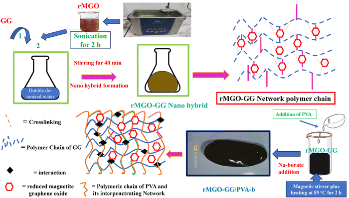 | ||
| Scheme 1 A schematic representation of the fabrication process of all-in-one solid state supercapacitor (DD = deionized water). | ||
3. Results and discussion
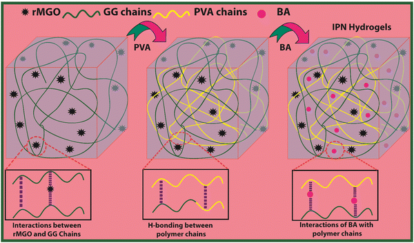
The present material was synthesized by incorporating a nanohybrid (NH) of GG with rMGO into the PVA matrix. The GG served as the bio-template material for uniformly distributed rMGO nanosheets within, and on the surface of, the naturally occurring bio-polymer. This was achieved by constant stirring for 2 h on a magnetic stirrer in 10 ml of deionized water. The solution was then heated to evaporate excess water, rendering the material more viscous and elastic. The PVA polymer was subsequently added gradually at room temperature, which allowed it to swell within the solution. The entire solution was then heated and stirred at 90 °C for 30 min to ensure the complete dissolution of the PVA. Finally, the physical crosslinker boric acid (BA) was slowly, and gently, added to ensure the uniform distribution until the solution reached a viscous state. This viscous solution was allowed to cool at room temperature, resulting in the final synthesis of PVA-based IPN hydrogel samples. The primary role of rMGO within the sample was to provide conductivity and mechanical strength to the synthesized hydrogels. To further enhance the 3D networking of the hydrogel, PVA was introduced as an IPN agent by dispersing the NH at 90 °C. The synthetic scheme of the IPN-based hydrogels, designed for a flexible, biodegradable, stretchable, and self-healing AIOS electronic device, such as a supercapacitor, is shown in Fig. 1.3.1. Characterization
The FTIR spectra of rMGO, rMGO-GG and the rMGO-GG/PVA-b were obtained and the results are shown in Fig. S1 (ESI†). Broad bands at 3113 and 3340 cm−1 for rMGO and rMGO-GG/PVA-b, respectively, indicated the –O–H stretching vibration. The peak for –O–H stretching vibration of rMGO appeared at 3113 cm−1 and shifted to 3340 cm−1 after incorporation in the hybrid hydrogel (rMGO-GG) which confirm the interactions due to the formation of inter- and intra-molecular H-bonding.34 This showed the successful incorporation of rMGO within the GG bio-templates. The peak at 2927 cm−1 for rMGO-GG and its hybrid rMGO-GG/PVA-b hydrogel was the –C–H asymmetric stretching vibration and is common in both, but this peak was absent in pure rMGO. Similarly, a peak at 1651 cm−1 in rMGO-GG was the –O–H bending vibration which was absent in rMGO, however, the appearance of the peak in rMGO-GG/PVA-b at 1735 cm−1 was the shifting of the peak, due to the interaction of rMGO with GG and its distribution within rMGO-GG/PVA-b.35 A peak at 1617 cm−1 was found in rMGO which was due to –C![[double bond, length as m-dash]](https://www.rsc.org/images/entities/char_e001.gif) C– or –C
C– or –C![[double bond, length as m-dash]](https://www.rsc.org/images/entities/char_e001.gif) C– in conjugation with the –C
C– in conjugation with the –C![[double bond, length as m-dash]](https://www.rsc.org/images/entities/char_e001.gif) O stretching vibration, it disappeared after incorporation in rMGO-GG, which confirmed the interaction between rMGO with GG. Two alternate peaks at 1353 and 1408 cm−1 in rMGO-GG showed the establishment of hydrogen bonding by GG with the rMGO sheets inside the polymeric chain network and –CH2– group wagging vibration of the carbon chain.36 The shifting of the peak of rMGO from 1088 to 995 cm−1 in rMGO-GG and the rMGO-GG/PVA-b shows the incorporation of rMGO. The disappearance of the peak at 872 cm−1 of pure rMGO after doping in rMGO-GG, and the dispersion of PVA-b in rMGO-GG also showed the establishment of H-bonding in the hydrogel network in the as-synthesized rMGO-GG/PVA-b.
O stretching vibration, it disappeared after incorporation in rMGO-GG, which confirmed the interaction between rMGO with GG. Two alternate peaks at 1353 and 1408 cm−1 in rMGO-GG showed the establishment of hydrogen bonding by GG with the rMGO sheets inside the polymeric chain network and –CH2– group wagging vibration of the carbon chain.36 The shifting of the peak of rMGO from 1088 to 995 cm−1 in rMGO-GG and the rMGO-GG/PVA-b shows the incorporation of rMGO. The disappearance of the peak at 872 cm−1 of pure rMGO after doping in rMGO-GG, and the dispersion of PVA-b in rMGO-GG also showed the establishment of H-bonding in the hydrogel network in the as-synthesized rMGO-GG/PVA-b.
The intense peak at 822 cm−1 and a small peak at 600 cm−1 in rMGO-GG/PVA-b was probably an indication of the –B–O–B stretching as well as the –B–O– bending vibration of the borate ion which was used as a crosslinker for the IPN formation of the hybrid rMGO-GG/PVA-b hydrogel.37 It was also noted from the FTIR spectra that after incorporation and mixing of rMGO-GG with PVA-b some peaks either disappeared or shifted, e.g., shifting of the peak at 1735 to 1651 cm−1 showed the interaction (complexation) of PVA-b and rMGO-GG. Similarly, the appearance of a peak at 1345 cm−1 in the rMGO-GG/PVA-b sample was another confirmation of the incorporation of rMGO-GG with the PVA.
The XRD patterns of GO, rMGO, GG-PVA-b, and rMGO-GG/PVA-b are shown in Fig. S2 (ESI†), and in Fig. S2(a) (ESI†) 2θ = 11.34° is the diffraction peak intensity of GO.38 This peak shows the spacing between the sheets of GO layers. The rMGO sample shows many peaks at 2θ = 2.29°, 15°, 20°, 30.08°, 34.97°, 52.02° and 67° as shown in Fig. S2(b) (ESI†). In addition, the peak of GO had now disappeared (blue circle region in Fig. S2(b), ESI†), and this shows that the Fe2O3 nanoparticles (NPs) are homogeneously incorporated which in turn enhances and increases the GO sheet spacing among the interlayers.39 Similarly, the XRD patterns of GG-PVA-b and rMGO-GG/PVA-b samples are shown in Fig. S2(c) and (d) (ESI†), respectively. The change in pattern indicated the interaction of rMGO with the surface functionalities of GG and its distribution within the PVA-b matrix.
The SEM images of the hybrid rMGO-GG/PVA-b2 hydrogel, pure GG, and pure rMGO which show the microscopic structure and 3D networking can be seen in Fig. S3 (ESI†). The porosity within the composite hydrogels together with their internal networking in the PVA medium show and support the electrochemical and conducting behavior as well as the building-up of the 3D network. The images of the composites exhibit the interconnectivity and porosity for the electronic and ionic mobility. The proper connectivity and porosity provided a 3D network for the synthesized hydrogels thus showing that a microstructure was developed for purposes such as the mechanical property as well as for the conductivity. The PVA became an IPN and produced entanglement within the rMGO-GG network which enhanced the mechanical characteristics.27 It was also found that in the pure GG-PVA hydrogels, the porosity varies but with a rough and unsmooth surface texture as shown in Fig. S3(a) and (b) (ESI†). However, after the incorporation of the rMGO sheets within the hydrogels, the porosity can be visualized in Fig. S3(c)–(e) (ESI†). The SEM image of pure GO shows its granular nature (Fig. S3(f), ESI†). Thus, these materials might have improved electrode surfaces (interface) and electrolytes, making them appropriate for uses such as flexible electronic devices.
3.2. Viscoelastic investigation
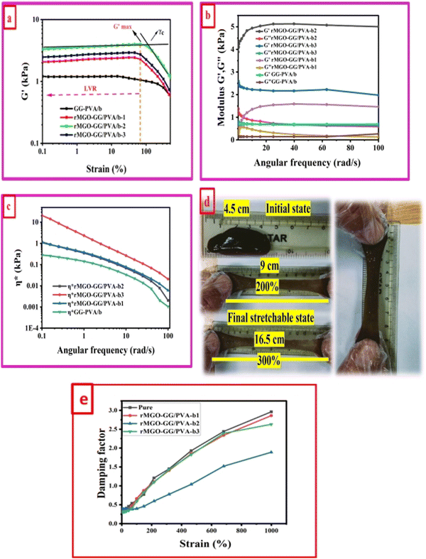
A study of the viscoelasticity was conducted by plotting percentage strain vs. G′ and G′′ (kPa) at an angular frequency (ω) of 10 rad s−1, a tolerance bandwidth of 10%, and a smoothing range of 5%, which clearly shows the elastic stimuli of the as-synthesized hydrogels which are one of its intrinsic properties both mechanically and dynamically. A strain amplitude measurement test (strain sweep) was performed to evaluate the LVR while keeping the G′ and G′′ effect independent of the change in percentage strain (see Fig. 2(a)). As the smoothing range for the entire study was 5%, a value was found which indicated the plateau of the synthesized materials. Deviation from this plateau is shown in Fig. 2(a) and is the deviation of the materials from the viscoelastic response, which is known as the critical strain of each sample.40 In the present work it was found that the material's strain was linear up to a critical strain, and after that a deformation occurred due to the collapse of microstructure and the viscoelastic response. This decreasing change in G′ showed the conversion from a semi-solid to semi-liquid state. It was found that the LVR was low for the pure sample whereas it was maximum for rMGO-GG/PVA-b2. Furthermore, it was also observed that increasing the wt% of the rMGO within the hydrogel network decreased the LVR as well as the crossover point (Fig. 2(a)). The amplitude sweep test was also helpful in determining the self-healing ability of the samples.41 Similarly, the
  was found to be 3.86, 2.71, 1.98, and 1.80 kPa for rMGO-GG/PVA-b2, rMGO-GG/PVA-b3, rMGO-GG/PVA-b1, and GG/PVA-b (pure without rMGO), respectively. This confirmed that the introduction of rMGO to the gel network greatly improved the elastic and viscous properties of the hydrogels. It was further found that all the samples that had rMGO had a higher G′ than the GG-PVA-b hydrogel composite. Such a finding supported the enhancement in the toughness and mechanical character of the synthesized hydrogel in the present work. The highest value of 3.86 kPa
  was for rMGO-GG/PVA-b2 out of all the samples compared to the value of 1.80 kPa for the pure composite hydrogel was almost 2.1 times tougher than the GG-PVA-b.
The viscous (G′′) and elastic (G′) nature of as-synthesized samples was determined as a function of angular frequency (ω) within limits from 0.1 to 100 rad s−1, at a strain γ of 1.0% in the LVER as shown in Fig. 2(b). The behavior of G′ and G′′ of all the samples were identical to each other but with different values. It was noted that both G′ and G′′ increased with an increase in ω. However, it would decrease until the microstructure was no longer stable above 100 due to the collapse of the 3D network of the hydrogels. The balanced network, microstructure, and higher G′ value of rMGO-GG/PVA-b2 when compared to the other samples were due to the presence and homogenized dispersion of rMGO within the hybrid hydrogel matrix. The lower the G′ value of the sample rMGO-GG/PVA-b3 was due to the higher wt% of rMGO with reference to the bio-template GG used as a dispersant as well as agglomeration of rMGO, whereas a lower G′ of rMGO-GG/PVA-b1 might show less wt% which created fewer crosslinking points. The sample of rMGO-GG/PVA-b2 exhibited the highest value of viscoelasticity (a G′ of 5.11 kPa) and it was 0.67 kPa for GG-PVA/b which was many times less. Another viscoelastic enhancement characteristic of rMGO-GG/PVA-b2 was found from the complex viscosity (η*) vs. ω plot. In the entire range of ω values, the viscoelastic property of rMGO-GG/PVA-b2 was higher although the complex viscosity decreased with an increase in the ω as shown in Fig. 2(c). A photographic representation of the as-synthesized hydrogels with different percentage strains is shown in Fig. 2(d) which shows the higher flexibility, viscoelastic nature, and self-healing ability. All of these properties of the sample rMGO-GG/PVA-b2 make it a better candidate for applications such as flexible electronic devices. The viscoelastic nature of the samples was further confirmed using the damping factor vs. percentage strain over a very long range (0% to 1000%). From the G′ and G′′, it was revealed that at the end of the LVR, the materials exhibit viscous behaviour starting from the elasticity. Similarly, all the samples at a higher deformation percentage strain range converted to a quasi-liquid state with higher damping values as shown in Fig. 2(e). With an increase in the percentage strain, the damping factor was linear which confirmed the collapse and damage of the microstructure at high deformation forces.42,43 However, it was also found that the damping factor of the rMGO-GG/PVA-b2 showed more resistance to deformation of the microstructure due to the better crosslinking points of the 3D network of the sample. The damping factor for all the samples followed the order: rMGO-GG/PVA-b2 > rMGO-GG/PVA-b3 > rMGO-GG/PVA-b1 > GG-PVA/b.
3.3. Effect of rMGO on conductivity
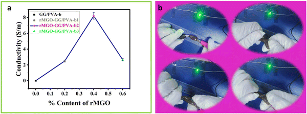
The effect of rMGO concentration on the conductivity of composite rMGO-GG/PVA-b hydrogels was studied. The conductivity of the synthesized samples was increased from 2.66 to 8.196 S m−1 with the addition of rMGO (0.4%), but further increases in rMGO within the hydrogel IPN network caused a decrease of conductivity to 2.46 S m−1 (Fig. 3(a)). The 0.2% in the pure PVA hydrogel increased the conductivity from 0 to 2.66 S m−1 in the rMGO-GG/PVA-b1, but there was an abrupt increase in the conductivity from 2.66 to 8.196 S m−1 for the rMGO-GG/PVA-b2 with 0.4% of rMGO. The low conductivity was probably due to the incomplete occupation of the rMGO within the in-built hydrogel IPN. On the other hand, the increase in the conductivity with an increase in the percentage of rMGO from 0.2% to 0.4% increased the conductivity to 8.196 S m−1 which was about six times higher than the conductivity rise. This indicated the efficient tunneling of electrons and ions within the hydrogel network in the form of electric current.44 This procedure enabled the conductivity improvement of the hydrogel and it was possible to achieve the conductive current tunneling from 0.2% to 0.4%. However, the situation was not gradual and the rMGO behave dual nature in the present study. First, these are better conductive materials than their precursor GO. Secondly, the rMGO also acts as a crosslinker which enhances the mechanical properties of the hydrogel.45 The conductivity of the hydrogel network was lost when the percentage content of rMGO was increased from 0.4 to 0.6 wt% and this may be due to the crossing over of the optimized and threshold percentage content value of rMGO (0.4%). Another reason for the lower conductivity in the rMGO-GG/PVA-b3 was the involvement of the extra rMGO content in the crosslinking, which reduced the conductivity of the current tunneling and thus, caused resistance to the flow of the electrons and ions within the hydrogel network.46 The presence of aqueous medium within the gel network provide a platform for a conduction and mobility of ions and electrons. Therefore, the better response of the present sample, regarding its capacitance in the cyclic voltammetry (CV) cycles, the galvanostatic charge discharge (GCD), and EIS, indicates that there was a good micropore size and surface suitability.47The hydrogel samples with the rMGO content were tested by twisting the sample while connecting it to an LED lamp as shown in Fig. 3(b). It was observed that the lighting of the sample was not affected even when completely twisted (Video 1, ESI†). This showed that in electronic devices, molding the shape whilst exerting some physical pressure did not affect the conductivity of the hydrogel as the IPN retained the conductivity tunneling current and pathways for the diffusion of ions and transport of electrons inside the gel matrix.
3.4. Self-healing ability and conductivity test
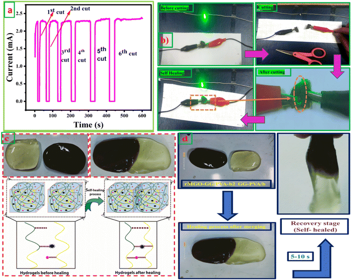
The self-healing ability and complete rebuilding of the damaged hydrogel network are of prime importance during the operation of the supercapacitors.48 The synthesis of PVA and GG-rMGO based hybrid hydrogels provided the interaction in reverse due to the presence of the physical crosslinking of the borate ion which gave an excellent self-healing property.48,49 The dynamic process of the hydrogel was checked while’ testing the measurement of current passing through the hydrogel after repeatedly cutting and stretching, and the subsequent healing steps as shown in Fig. 4(a). As the conductivity of the material was sustained and better, the sample rMGO-GG/PVA-b2 showed a glowing LED bulb consistently allowing the current within the closed loop circuit system. The hydrogel was cut into segments and combined through self-healing six times, it was observed that the cutting causes off the light due to the opening of the loop circuit while on again after reconnecting the two surfaces quickly (self-healing) and the current flowed again. This practical demonstration indicated the re-building and self-healing process of the synthesized material as shown in Fig. 4(b). Furthermore, the as-synthesized 3D hydrogel sustained its conductivity well after every cut (six cutting cycles) with respect to time. This was because of the reversible self-healing generation of the physically crosslinking borate ion, which showed complexation with the polymeric chains of the network.50,51 The mechanical and conducting properties of rMGO-GG/PVA-b2 after each cut and healing cycle made the gel material fit for use as a flexible and self-healable electrode and separator system for practical applications. This property of the rMGO-GG with a PVA borax-based matrix as a passage for transporting electrons with minimum resistance, homogenized porosity (micropores) establishment inside the network, intrinsic observable healing due to reversible interaction, enhanced conductivity, and excellent viscoelastic flexibility is shown in Fig. 4(c) and (d).3.5. Electro-mechanical response of hydrogels
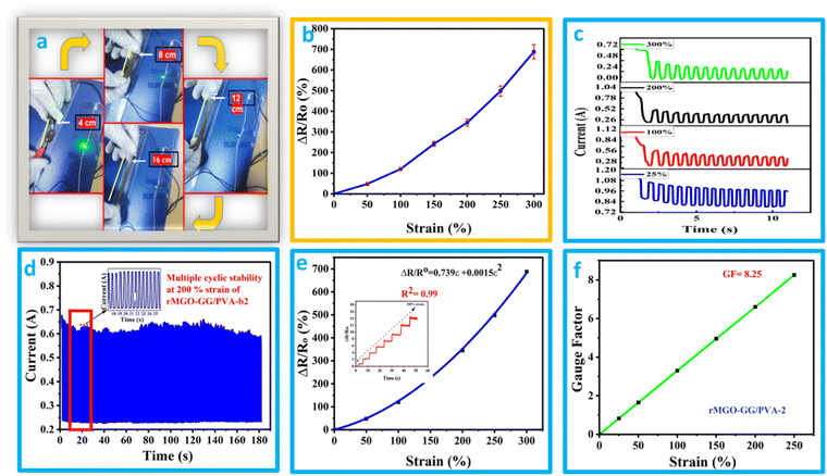
It was found that the flexible conductive hydrogel on deformation by stretching changed the current response and this was observed by an LED bulb demonstration (Fig. 5(a) and (b) and Video 2, ESI†). The hydrogels showed better stretchability, conductivity, and additional stability which in turn enhanced its suitability for use as a soft electronic material in electronic devices. In addition to the previously mentioned function, the materials have a sensing response, which was measured by the change in the relative resistance using the equation ΔR/Ro = R − Ro/Ro, where R is resistance during stretching deformation, and Ro is the initial state (without stretching). The graph of ΔR/Rovs. applied strain was plotted. It was found that the rMGO-GG/PVA-b2 hydrogel used as a sensor could be deformed up to 250% of strain, and the resistance was raised with respect to an increase in the strain value. As the stretching occurs from 0% to 300%, the conductivity was observed by the illumination of the LED bulb dimming and brightening demonstration (Fig. 5(a) and (b)). However, a further increase in stretching enhanced the resistance which darkened the LED bulb due to the loss of the rMGO active materials and hindered the electronic flow. This process basically increased the spacing within the 3D network for electron transport as well as lengthening the tunneling to provide a current barrier against losing the conductivity ability of the as-synthesized materials.52The hydrogels due to the presence of electrolytes and conducting materials were tested using chrono amperometry to determine the current response and conductive properties at different strains ranging from 25% to 300% deformation. A decrease in current with an increase in strain and time was observed (Fig. 5(c)). This electro-mechanical performance of the hydrogels was due to the IPN pattern of the polymeric composite network. However, the electrically conductive nature was due to the presence of K+ and OH− ions working as an electrolyte within the hydrogels as well as the presence of rMGO embedded in the matrix. The conductivity response of the hydrogels was basically the presence of pore channels inside the matrix together with a huge amount of water having the capability of creating the network which provides the path for transmission of ions and electrons. Due to the stretching, these transmission lines become narrow which slows down the transmission of ions and electrons, and as a consequence the current flow inside the hydrogels was disturbed, and the network responded to the applied strain. The cyclic stability of the materials was also tested at strains of up to 200% for up to 180 cycles as shown in Fig. 5(d). It was found that on gradual stretching and relaxation (release) the current was stable, indicating the better cyclic stability of the hydrogel which is one of the intrinsic characteristics of the as-synthesized materials. Mostly the term gauge factor (GF) has been used to elaborate the sensitivity of the strain sensors. The rMGO-GG/PVA-b2 was used to determine the strain sensitivity of the IPN network hydrogel according to a previously reported method in the literature.53 The GF was calculated by using the equation GF = (ΔR/Ro)/ε, where (ΔR/Ro) is the relative resistance of the hydrogels and ε is the applied strain. Similarly, the GF was determined using the equation ΔR/Ro = 0.739ε + 0.00513ε2 that was obtained from the polynomial fitting of relative resistance vs. applied strain (Fig. 5(e)). The calculated GF value was 8.25 at 200% strain (Fig. 5(f)) which was better than that found in most of the previously reported research. These results clearly demonstrated that the prepared IPN hydrogels had an excellent response to large strain, with high stability, high sensitivity, and could be utilized as soft flexible electronic device for wearable electronics, flexible supercapacitors, and so on.
3.6. Electrochemical response of the hydrogels
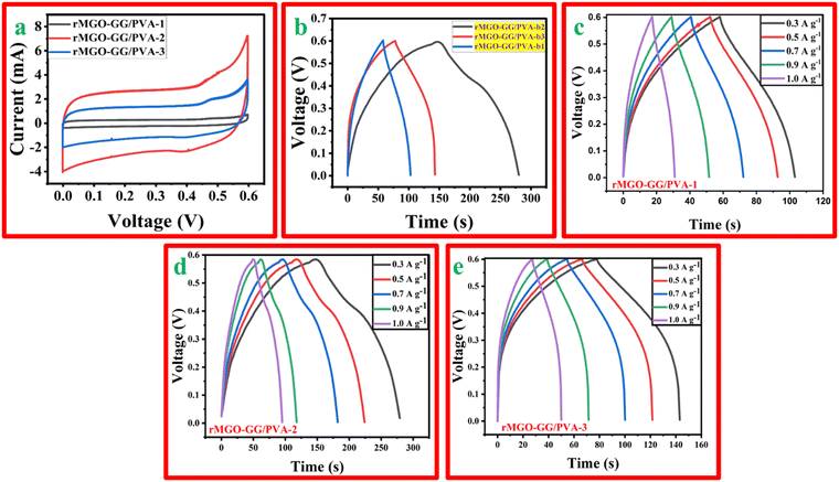
The synthesized hydrogels with different wt% of the active material, rMGO were tested using CV, GCD, and EIS using a three electrode system with an electrochemical work station. The CV profile of rMGO-GG/PVA-b1, rMGO-GG/PVA-b2, and rMGO-GG/PVA-b3 was measured at different scan rates (5 mV s−1 to 100 mV s−1). However, the material was properly kept for a CV profile at a scan rate of 50 mV s−1. Fig. 6(a) shows that the CV curves obtained in the present study approached a symmetrical rectangular steady shape, which indicated the characteristic of a typical electric double-layer capacitor (EDLC). The area enclosed by the CV curve provided the highest specific capacitance of the synthesized hydrogels.54 The rMGO-GG/PVA-b2 showed the highest current peak and enclosed area compared to the other samples. Furthermore, the CV profile was also more symmetrical in shape as well as rectangular with a better stability within the given potential window. Therefore, the rMGO-GG/PVA-b2 had the highest value of specific capacitance together with the higher performance of the capacitance property. The specific capacitance was calculated from the loop area of the CV curve and from the weight of materials using the equation Cs = A/m·k·ΔV, where Cs is the specific capacitance, A is integrated area of the loop of CV curve, m is the mass (g) of the electrode material, k is the scanning rate (mV s−1), and ΔV is the potential window (V). The Cs values for rMGO-GG/PVA-b2, rMGO-GG/PVA-b3, and rMGO-GG/PVA-b1 were: 85 F g−1, 41.83 F g−1, and 8.5 F g−1, respectively, with the scan rate of 50 mV s−1.Similarly, in the GCD study there were symmetrical triangular curves for rMGO-GG/PVA-b1 and rMGO-GG/PVA-b3, whereas for rMGO-GG/PVA-b2 a slight asymmetrical triangle curve was obtained (Fig. 6(b)). This shows that rMGO-GG/PVA-b2 had a better capacitive performance.55 The Cs values for the hydrogels from the GCD curves were calculated from equation: Cs = I·Δt/m·ΔV, where I/m is the current density (A g−1) and ΔV is potential window (V). The Cs values obtained for rMGO-GG/PVA-b2, rMGO-GG/PVA-b3 and rMGO-GG/PVA-b1 were 108.33 F g−1, 54.16 F g−1, and 37.5 F g−1, respectively. The specific capacitance of rGO-based hydrogel electrodes was much better than that of other materials with Fe3O4-based electrode.56 The comparative key performance parameters for the present work are shown in Table 1.
| Hydrogel | Current density | Specific capacitance | Ref. |
|---|---|---|---|
| PVA-PAx hydrogels | 1 A g−1 | 64.8 F g−1 | 57 |
| Poly(vinyl alcohol)/gelatin hydrogel electrolyte (PGN) | 1 A g−1 | 83.6 F g−1 | 58 |
| Montmorillonite@graphene-like carbon nanosheets (P-MMT@C) | 10 A g−1 | 100 F g−1 | 59 |
| (rGO)/Polypyrrole nanotube (PPy NT) | 0.1 A cm−3 | 59.9 F cm−3 | 60 |
| Magnetite and pyrrole treated magnetite film electrodes | 0.1 A g−1 | 106 F g−1 | 56 |
| Methacrylated graphene oxide (MGO-PAA)w | 0.1 A g−1 | 63.6 F g−1 | 61 |
| rMGO-GG/PVA-b | 0.3 A g−1 | 108.33 F g−1 | Current study |
Furthermore, the response of the electrode materials in all the samples were sharp during the charging–discharging process which was due to small internal resistance (IR) drop. A smaller drop in IR indicates that the electrode materials have a better capacitive performance. The capacitive performance of the materials is important especially for energy storage systems and devices due to low amount of energy wasted in the form of heat.62 Thus, it is one of the important findings that doping of Fe2O3 within the GO, and then its reduction and incorporation inside the hydrogel, enhanced the conductive and electrochemical behavior of hydrogel assembled electrode in the three electrode system. However, the lower specific capacitance of rMGO-GG/PVA-b3 when compared to rMGO-GG/PVA-b2 was due to the constant wt% of GG (bio-template dispersant). Because of the increase in the wt% of rMGO, there was not enough GG for complete dispersion and most of the rMGO remained. This caused the aggregation of rMGO, and in turn the loss of the non-stop conductivity of rMGO within the hydrogel matrix. The GCD curves for the hydrogels at various current densities ranging from 0.3 A g−1, 0.5 A g−1, 0.7 A g−1, and 1.0 A g−1 are shown in Fig. 6(c)–(e).
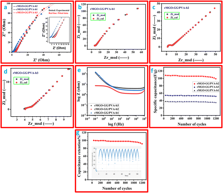
The electrochemical impedance study was performed and the Nyquist plot is shown in Fig. 7(a), and a two-frequency profile was found. At first the higher frequency of all the samples gave semi-circles which shows the electron transfer procedure between the electrode, and secondly, the electrolyte interface which was the IR, which shows the electrolyte resistance, and the material that has been used as an electrode. In addition, the inclined line at the low frequency range was the Warburg constant impedance which indicated the charge diffusion of the active electrode materials. Such phenomena indicate a better performance of the substance. The IR values (from the semi-circle intercept on the horizontal axis) were: 1.22 Ω, 3.75 Ω, and 4.01 Ω for rMGO-GG/PVA-b2, rMGO-GG/PVA-b1, and rMGO-GG/PVA-b3, respectively, at a high frequency range (ƒ). Similarly, the charge transfer resistance (Rct) was found from the diameter of the entire semi-circle of the Nyquist plot. The Rct values for rMGO-GG/PVA-b2, rMGO-GG/PVA-b1, and rMGO-GG/PVA-b3 were: 3.416, 4.25, and 6.09 Ω, respectively. In the present case, 5 mV was chosen to avoid damaging the samples, because the voltage was the external force for the determination of the electrochemical properties on the electrode surface. Furthermore, the low voltage selection was mostly chosen to keep the signals linear within the given range. As EIS is a non-destructive method, the low voltage selection was used to improve the safety range of the samples and to ensure accurate measurements.63,64
The previously mentioned value of resistance for rMGO-GG/PVA-b2 showed the least resistance among the as-synthesized samples of the hydrogel materials. This was perhaps due to the better porosity with an excellent 3D network, which in turn decreased the resistance of electrolytes used during the study, and this porous structure provided a low resistance pathway for the electrolytes with a better capacitive performance. The straight line in the low frequency range showed the unadulterated capacitance performance of the material. Such phenomena support the uninterrupted ionic diffusion of the electrolytes within the porous path. The Rs value decreased from rMGO-GG/PVA-b1 (Fig. 7(b)) to rMGO-GG/PVA-b2 (Fig. 7(c)) which was due to the uniform dispersion of the rMGO within the hydrogel network. However, it was found from the results that by increasing the amount of rMGO in the rMGO-GG/PVA-b3 (Fig. 7(d)), the Rs value abruptly increased which was due to the disappearance of the active sites available for the attachment of rMGO in the bio-template GG, as well as the agglomeration of rMGO and this disturbed the homogenized dispersion. Furthermore, this agglomeration also blocked the pores for ionic diffusion, therefore, the Rs increases for rMGO-GG/PVA-b3.65
The impedance effect (EIS) with the concentration of rMGO was also studied using a Bode plot as shown in Fig. 7(e). The incorporation of the rMGO-GG within the network first showed decreases in the impedance from rMGO-GG/PVA-b1 to rMGO-GG/PVA-b2, and then an abrupt increase for rMGO-GG/PVA-b3. The rMGO-GG/PVA-b2 showed a better result in both the high and low frequency ranges. The stability of the as-synthesized samples was determined from the cyclic stability of multiple cycles. The GCD testing of multiple cycles was carried out between the specific capacitance of the electrode vs. number of cycles at a current density of 0.3 A g−1 and the results are shown in Fig. 7(f). It was found that the specific capacitance of rMGO-GG/PVA-b1, rMGO-GG/PVA-b2, and rMGO-GG/PVA-b3 were stable with little fluctuation in the capacitance value after 1200 cycles. Furthermore, the capacitance percentage retention was found to be 91.39%, 94.97%, and 92.32% for rMGO-GG/PVA-b2, rMGO-GG/PVA-b3 and rMGO-GG/PVA-b1, respectively, after 1200 cycles.
The performance of the hydrogels was more stable and better than that reported previously in the literature. The capacitance retention (%) of Fe2O3 and Fe2O3/RGO was 69.2% and 86.9% after 1000 cycles,7 respectively, and for Fe2O3/CNT-rMGO was it was reported to be 82.5% for 1000 cycles.35 The stability of the hydrogel electrode showed the synergistic behavior for rMGO-GG, and its stable conductivity in the paths within the hydrogel network. Such structural configuration provided a better stability by preventing the agglomeration of rMGO, minimized the resistance, changed the IPN structure, and possibly the crosslinking. Thus, this may lead to the enhanced mechanical property, with less resistive ion paths for diffusion, a porous surface with a higher surface-active area, and give the material excellent electrochemical conductivity and stability even after many hundreds of cyclic operations.
3.7. Device fabrication and its electrochemical performance as a supercapacitor
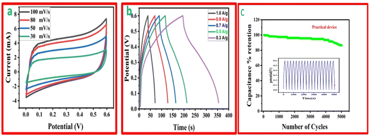
The function, diagrammatic representation, and electrochemical properties of the symmetrically stretchable and flexible AIOS device are shown in Fig. 8. The practical device was devised just like a sandwich having a solid electrolyte of GG-PVA-b in between two layers of rMGO-GG/PVA-b2. In these sandwiches, the GG-PVA-b which had been kept in 6 M KOH solution for overnight and was loaded with ions. The rMGO-GG/PVA-b2 hydrogel behaved as a current collector as well as a working electrode. The electrolyte and composite had connected with each other due to better adhesion of the surface functionalities without any need for binders. The materials were amalgamated tightly with each other, thus working as a single AIOS device in a two electrode system. The counter and working electrodes were united and acted as a single electrode. Similarly, the electrochemical tests were performed to determine the capacitive action of the practical supercapacitor using CV at different scan rates ranging from 30 mV s−1 to 100 mV s−1 as shown in Fig. 8(a), and GCD with various current densities ranging from 0.1 to 0.9 A g−1. The results indicated that the CV exhibited its rectangular shape at all scan rates (30 to 100 mV s−1), which confirmed the better current flow and excellent voltage. Such behavior indicated the uninterrupted ionic mobility within the hydrogels’ networks to maintain the conductivity of the synthesized materials. Similarly, Fig. 8(b) shows the symmetrical shape (triangular type) of GCD, which shows the first-rate capacitive characteristics required during practical processing and operation. The GCD specific capacitance data was calculated as 106.66, 91.2, 86.33, 85 and 53.33 F g−1 at a current densities of 0.3, 0.5, 0.7, 0.9, and 1.0 A g−1, respectively. Similarly, the assembled device used for multiple cycles retained a percentage capacitance of 86.48% even after 5020 cycles at 1.0 A g−1 of current density as shown in Fig. 8(c). Thus, it confirms the cyclic stability of the assembled supercapacitor after practical operation. Such electrochemical properties of the hydrogels were due to the IPN and porosity in the structure enhancing the conductivity. The present supercapacitor can replace the traditional capacitor which had liquid electrolytes which had limitations such as leakages, evaporation, less flexibility, and wearability during their routine operation.Similarly, a schematic of the fabrication process, and photographs of it are shown in Fig. 9. The pure hydrogel GG-PVA/b was kept in 6 M KOH electrolyte solution for 8 h, and then sandwiched between two layers of rMGO-GG/PVA-b2 hydrogel, and the layers were pressed together for 30 min. Both the rMGO hydrogels were connected separately by the nickel foam, and this was for the electrical connection for the illumination of the LED bulb. Then the AIOS supercapacitor sandwich was placed in an oven at 40 °C to evaporate the excess water to complete the assembly.
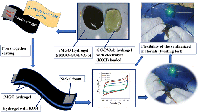 | ||
| Fig. 9 A schematic of the fabrication process, of the all-in-one solid-state supercapacitor. (Twisting test and press together casting). | ||
4. Conclusion
In summary, a multi-functional interpenetrating network (IPN) hydrogel has been successfully synthesized. This process involved the homogeneous dispersion and incorporation of reduced magnetite graphene oxide (rMGO) sheets into a GG matrix, followed by the dispersion of PVA hydrogel into the rMGO and GG solution, and subsequent physical crosslinking with boric acid (BA). The GG acted as a bio-template, ensuring the uniform dispersion and stability of the rMGO sheets, so that a stable colloidal system was formed. Borate ions served as physical crosslinkers, facilitating the possible interactions. The presence of rMGO improved the mechanical properties and conductivity of the hydrogels, whereas PVA and GG enhanced flexibility and stretchability within the network. The borax ions, as physical crosslinkers, enhanced the bonding during the self-healing process. The storage modulus was observed to be 3.86 kPa and 5.11 kPa as a function of percentage strain and angular frequency (rad s−1), respectively, in the LVR. The hydrogels displayed an outstanding self-healing ability, recovering within 5–10 s. This combination of flexibility and self-healing makes them highly suitable for practical use in electronic devices.The all-in-one solid-state supercapacitor exhibited superior conductivity responses in both CV and GCD. A capacitance of 85 F g−1 was recorded with CV, while the specific capacitance was 106.66 F g−1 with GCD for the self-assembled practical device. The internal resistance was measured at 1.22 Ω, 3.75 Ω, and 4.01 Ω for rMGO-GG/PVA-b2, rMGO-GG/PVA-b1, and rMGO-GG/PVA-b3, respectively. The Bode and Nyquist plots were employed to correlate the experimental and theoretical data. The hydrogel demonstrated a gauge factor of 8.25 and ionic conductivity of 0.89 S m−1 at 200% strain. Furthermore, the specific capacitance showed a retention of 94.97% after 1200 cycles, which confirming its enhanced stability. The practical device showed a retention of 86% after 5000 cycles. The material also responded to various physical deformations, particularly the illumination of an LED bulb. It was observed that LED illumination remained unaffected even when the conducting hydrogel was twisted by 180°. Hence, these hydrogels show great potential as candidates for soft electronic devices, and in green chemistry, given their electrochemical and biopotentials, particularly in environmental applications.
Conflicts of interest
No conflicts of interest exist to declare.References
- B. C. Tee, C. Wang, R. Allen and Z. Bao, Nat. Nanotechnol., 2012, 7, 825–832 CrossRef CAS
.
- Y. Jing, X. Yuan, Y. Xu, J. Hou, X. Yu, B. Ye and Y. Li, Adv. Opt. Mater., 2023, 11, 2202517 CrossRef CAS
.
- S. Sardana, A. Gupta, K. Singh, A. Maan and A. Ohlan, J. Energy Storage, 2022, 45, 103510 CrossRef
.
- Y. Liu, L. Wang, Y. Mi, S. Zhao, S. Qi, M. Sun, B. Peng, Q. Xu, Y. Niu and Y. Zhou, J. Mater. Chem. C, 2022, 10, 13351–13371 RSC
.
- M. Khan, L. A. Shah, L. Ara, R. Ullah and H.-M. Yoo, Chem. Mater., 2023, 35(14), 5582–5592 CrossRef CAS
.
- M. Khan, L. A. Shah, S. Yazdani and H.-M. Yoo, Sens. Actuators, A, 2023, 114363 CrossRef CAS
.
- Y. Jiang, J. Han, X. Wei, H. Zhang, Z. Zhang and L. Ren, Materials, 2022, 15, 5371 CrossRef
.
- J. Gamboa, S. Paulo-Mirasol, F. Estrany and J. Torras, ACS Appl. Bio Mater., 2023, 6, 1720–1741 CrossRef PubMed
.
- M. Khan, L. A. Shah, T. U. Rahman, H.-M. Yoo, D. Ye and J. Vacharasin, ACS Appl. Polym. Mater., 2022, 4, 7397–7407 CrossRef
.
- R. Ullah, L. A. Shah, M. Khan and L. Ara, Int. J. Biol. Macromol., 2023, 125666 CrossRef PubMed
.
- J. Sun, B. Luo and H. Li, Adv. Energy Sustainability Res., 2022, 3, 2100191 CrossRef
.
- T. Xu, K. Liu, N. Sheng, M. Zhang, W. Liu, H. Liu, L. Dai, X. Zhang, C. Si and H. Du, Energy Storage Mater., 2022, 48, 244–262 CrossRef
.
-
H. T. Das, S. Dutta, P. Das, N. Das and G. A. Ali, Handbook of Biodegradable Materials, Springer, 2022, pp. 1–25 Search PubMed
.
- N. M. Badawi, M. Bhatia, S. Ramesh, K. Ramesh, M. Kuniyil, M. R. Shaik, M. Khan, B. Shaik and S. F. Adil, Polymers, 2023, 15, 571 CrossRef CAS
.
- K. Sun, S. Cui, X. Gao, X. Liu, T. Lu, H. Wei, H. Peng and G. Ma, J. Energy Storage, 2023, 61, 106658 CrossRef
.
- M. Khan, L. A. Shah, M. A. Khan, N. S. Khattak and H. Zhao, Mater. Sci. Eng., C, 2020, 116, 111278 CrossRef CAS PubMed
.
- J. Zhao, Y. Lu, Y. Liu, L. Liu, J. Yin, B. Sun, G. Wang and Y. Zhang, Nanomaterials, 2023, 13, 380 CrossRef CAS PubMed
.
- Y. Zhao, Q. Liang, S. M. Mugo, L. An, Q. Zhang and Y. Lu, Adv. Sci., 2022, 9, 2201039 CrossRef CAS
.
- Y. Liang, Z. Wang, J. Huang, H. Cheng, F. Zhao, Y. Hu, L. Jiang and L. Qu, J. Mater. Chem. A, 2015, 3, 2547–2551 RSC
.
- A. G. Olabi, Q. Abbas, A. Al Makky and M. A. Abdelkareem, Energy, 2022, 248, 123617 CrossRef CAS
.
- W. Sun, J. Yang, X. Ji, H. Jiang, L. Gai, X. Li and L. Liu, Sustainable Mater. Technol., 2022, 32, e00437 CrossRef CAS
.
- X. Liu, M. Gao, J. Chen, S. Guo, W. Zhu, L. Bai, W. Zhai, H. Du, H. Wu and C. Yan, Adv. Funct. Mater., 2022, 32, 2203323 CrossRef CAS
.
- A. Khorate and A. V. Kadam, J. Energy Storage, 2022, 52, 104887 CrossRef
.
- Y. Qiu and K. Park, AAPS PharmSciTech, 2003, 4, 406–412 CrossRef CAS
.
- Y. Liang, J. Xue, B. Du and J. Nie, ACS Appl. Mater. Interfaces, 2019, 11, 5441–5454 CrossRef CAS PubMed
.
- P. Lin, S. Ma, X. Wang and F. Zhou, Adv. Mater., 2015, 27, 2054–2059 CrossRef CAS
.
- I. Ali, L. Ali Shah, T. U. Rehman and S. Faizan, J. Polym. Res., 2022, 29, 1–12 CrossRef
.
- L. Hu, P. L. Chee, S. Sugiarto, Y. Yu, C. Shi, R. Yan, Z. Yao, X. Shi, J. Zhi and D. Kai, Adv. Mater., 2023, 35, 2205326 CrossRef CAS PubMed
.
-
R. S. Lakes, Viscoelastic Solids (1998), CRC Press, 2017 Search PubMed
.
- M. Wang, L. Fan, G. Qin, X. Hu, Y. Wang, C. Wang, J. Yang and Q. Chen, J. Membr. Sci., 2020, 597, 117740 CrossRef CAS
.
- S. A. Khan, T. U. Rehman, L. A. Shah and M. Ullah, Chem. Pap., 2023, 77, 2725–2735 CrossRef CAS
.
- L. A. Shah, T. U. Rehman and M. Khan, Polym. Bull., 2020, 77, 3921–3935 CrossRef CAS
.
- V. Loryuenyong, K. Totepvimarn, P. Eimburanapravat, W. Boonchompoo and A. Buasri, Adv. Mater. Sci. Eng., 2013, 2013, 923403 Search PubMed
.
- S. Huan, L. Bai, W. Cheng and G. Han, Polymer, 2016, 92, 25–35 CrossRef
.
- J. Sun, P. Zan, X. Yang, L. Ye and L. Zhao, Electrochim. Acta, 2016, 215, 483–491 CrossRef
.
- J. Han, C. Zhou, Y. Wu, F. Liu and Q. Wu, Biomacromolecules, 2013, 14, 1529–1540 CrossRef
.
- M. H. Kahsay, N. Belachew, A. Tadesse and K. Basavaiah, RSC Adv., 2020, 10, 34916–34927 RSC
.
- M. Khan, L. A. Shah, T. Rehman, A. Khan, A. Iqbal, M. Ullah and S. Alam, Iran. Polym. J., 2020, 29, 351–360 CrossRef
.
- L. T. M. Thy, N. H. Thuong, T. H. Tu, N. H. T. My, H. H. P. Tuong, H. M. Nam, M. T. Phong and N. H. Hieu, Adsorpt. Sci. Technol., 2020, 38, 240–253 CrossRef
.
- T. B. Goudoulas, A. Didonaki, S. Pan, E. Fattahi and T. Becker, Polymers, 2023, 15, 1558 CrossRef CAS PubMed
.
- G. Stojkov, Z. Niyazov, F. Picchioni and R. K. Bose, Gels, 2021, 7, 255 CrossRef CAS
.
- Y. Shi, B. Wu, S. Sun and P. Wu, Nat. Commun., 2023, 14, 1370 CrossRef CAS PubMed
.
- D. Li, L. Feng, F. Han, S. Hao, Q. Wu, Y. Gao, Y. Li, X. Qin and M. He, ACS Appl. Nano Mater., 2023, 6, 3012–3019 CrossRef CAS
.
- Y. Zhang, Y. Tan, J. Lao, H. Gao and J. Yu, ACS Nano, 2023, 17(11), 9681–9693 CrossRef CAS
.
- C. Lin, D. Sheng, X. Liu, S. Xu, F. Ji, L. Dong, Y. Zhou and Y. Yang, Polymer, 2018, 140, 150–157 CrossRef CAS
.
- P. Chettri, A. Tripathi and A. Tiwari, Mater. Res. Bull., 2022, 150, 111752 CrossRef CAS
.
- C. Zequine, C. K. Ranaweera, Z. Wang, S. Singh, P. Tripathi, O. N. Srivastava, B. K. Gupta, K. Ramasamy, P. K. Kahol, P. R. Dvornic and R. K. Gupta, Sci. Rep., 2016, 6, 31704 CrossRef CAS PubMed
.
- K. Peng, J. Zhang, J. Yang, L. Lin, Q. Gan, Z. Yang, Y. Chen and C. Feng, ACS Appl. Mater. Interfaces, 2022, 14, 39404–39419 CrossRef CAS PubMed
.
- Z. Nie, K. Peng, L. Lin, J. Yang, Z. Cheng, Q. Gan, Y. Chen and C. Feng, Chem. Eng. J., 2023, 454, 139843 CrossRef CAS
.
- L. Pang, Y. Shen, H. Hu, X. Zeng, W. Huang, H. Gao, H. Wang and D. Wang, Mater. Sci. Eng., C, 2019, 105, 110076 CrossRef CAS
.
- J. Wu, X. Wu, F. Yang, X. Liu, F. Meng, Q. Ma and Y. Che, Int. J. Biol. Macromol., 2023, 225, 1119–1128 CrossRef CAS
.
- Q. Rong, W. Lei, L. Chen, Y. Yin, J. Zhou and M. Liu, Angew. Chem., Int. Ed., 2017, 56, 14159–14163 CrossRef CAS PubMed
.
- M. Khan, L. A. Shah, T. U. Rahman, H.-M. Yoo, D. Ye and J. Vacharasin, J. Mech. Behav. Biomed. Mater., 2023, 138, 105610 CrossRef CAS PubMed
.
- Z. Wang, H. Li, Z. Tang, Z. Liu, Z. Ruan, L. Ma, Q. Yang, D. Wang and C. Zhi, Adv. Funct. Mater., 2018, 28, 1804560 CrossRef
.
- H. Jia, S. Lu, S. H. R. Shin, M. L. Sushko, X. Tao, M. Hummel, P. K. Thallapally, J. Liu and Z. Gu, J. Power Sources, 2022, 526, 231163 CrossRef CAS
.
- X. Zhao, C. Johnston, A. Crossley and P. S. Grant, J. Mater. Chem., 2010, 20, 7637–7644 RSC
.
- L. Zhao, Q. Ling, X. Fan and H. Gu, ACS Appl. Mater. Interfaces, 2023, 15, 40975–40990 CrossRef CAS
.
- B. Hou, X. Li, M. Yan and Q. Wang, Eur. Polym. J., 2023, 185, 111826 CrossRef CAS
.
- Y. Yang, R. Xiao, X. Sun, L. Lu and Y. Chen, Mater. Chem. Phys., 2022, 287, 126333 CrossRef CAS
.
- C. Yang, L. Zhang, N. Hu, Z. Yang, H. Wei and Y. Zhang, J. Power Sources, 2016, 302, 39–45 CrossRef CAS
.
- X. Jin, G. Sun, H. Yang, G. Zhang, Y. Xiao, J. Gao, Z. Zhang and L. Qu, J. Mater. Chem. A, 2018, 6, 19463–19469 RSC
.
- V. Kuzmenko, O. Naboka, M. Haque, H. Staaf, G. Göransson, P. Gatenholm and P. Enoksson, Energy, 2015, 90, 1490–1496 CrossRef CAS
.
- A. Kundu and T. S. Fisher, ACS Appl. Energy Mater., 2018, 1, 5800–5809 CrossRef
.
- S. Akbulut, M. Yilmaz, S. Raina, S.-H. Hsu and W. P. Kang, Diamond Relat. Mater., 2017, 74, 222–228 CrossRef
.
- D. Liu, C. Fu, N. Zhang, H. Zhou and Y. Kuang, Electrochim. Acta, 2016, 213, 291–297 CrossRef
.
Footnote |
| † Electronic supplementary information (ESI) available. See DOI: https://doi.org/10.1039/d3ma00803g |
| This journal is © The Royal Society of Chemistry 2024 |

