
 Open Access Article
 This Open Access Article is licensed under a Creative Commons Attribution-Non Commercial 3.0 Unported Licence
Two-photon microscopy of acoustofluidic trapping for highly sensitive cell analysis
Thomas
Kellerer†
 a,
Bettina
Sailer†
b,
Patrick
Byers
a,
Rune
Barnkob
c,
Oliver
Hayden
b and
Thomas
Hellerer
*a
a,
Bettina
Sailer†
b,
Patrick
Byers
a,
Rune
Barnkob
c,
Oliver
Hayden
b and
Thomas
Hellerer
*a
aMultiphoton Imaging Lab, Munich University of Applied Sciences, 80335 Munich, Germany. E-mail: thomas.hellerer@hm.edu
bHeinz-Nixdorf-Chair of Biomedical Electronics, School of Computation, Information and Technology, Technical University of Munich, TranslaTUM, 81675 Munich, Germany
cMicrofluidics Solutions, 00154 Rome, Italy
First published on 19th June 2024
Abstract
We combine two-photon-excited fluorescence microscopy and acoustofluidic trapping in a spherical microchamber to in vitro study cells and cell clusters three-dimensionally close to in vivo conditions. The two-photon microscopy provides the in-depth 3D analysis of the spherical microchamber dimensions as well as the positions of trapped samples therein with high spatial precision and high temporal resolution enabling even tracking of the fast moving particles. Furthermore, optical sectioning allows to gather information of individual cells in trapped cell clusters inside the chamber. We demonstrate real-time monitoring of osmosis in A549 lung cells and red blood cells as one possible biomedical application. The observed osmosis reduced the cell membrane diameter by approximately 4 μm in the A549 cells and by approximately 2 μm in the red blood cells. Our approach provides an important optical tool for future investigations of cell functions and cell–cell interactions avoiding wall-contact inside an acoustofluidic device.
1 Introduction
Many patients suffer from acute chronic inflammation, which can lead to cancer, autoimmunity, or cardiovascular diseases.1 Understanding the influence of the immune system on different etiologies is important for future personalization of therapies. However, as discussed by Chattopadhyay et al.,2 most cell functional analysis methods are performed on a single-cell level or in 2D with a limited spatiotemporal resolution for the 3D. Today, we have many ways for preclinical research, but only some standardizable cell function methods are available for clinical routine diagnostics.3 Amongst other reasons, most cell function methods require a large amount of patient samples for, e.g., fluorescence flow cytometry, which is rarely the case.4,5 In particular, the complex interactions of cells, such as the tumor microenvironment, are a significant challenge for standardized diagnostic measurements and the development of personalized therapies. The only functional analysis method in 3D accepted by regulatory authorities is animal testing for pharma studies with limited translational value.6 Most recently, organoid or tumoroid analysis in 3D using non-standardizable Matrigel as a preferred matrix has been of general interest. Still, all these methods require a time-to-result over even weeks, which is inappropriate for clinical diagnostics. Rapid time-to-result methods are very important as in case of acute inflammation, it can lead to sepsis in the worst case. In the case of chronic inflammation, a long time-to-result can lead to tissue destruction which causes the previously mentioned diseases.7A promising field for an in vitro cell analysis method that works under near in vivo conditions is the combination of microfluidics and acoustics, often referred to as acoustofluidics. This combination of techniques offers touch-free cell manipulation in 3D, fast time-to-result, and a high potential for standardization with a minimum amount of cells. The field of microfluidics allows the investigation of cell suspensions in small volumes and within a very short time.8 The acoustic part of the technology permits the purely mechanical manipulation of cells and particles in an acoustic pressure field induced by ultrasonic piezo-actuation of microfluidic systems. The theoretical and practical working principle of using acoustofluidics for particle analysis has been published for over a decade. However, previous works in acoustofluidics have been focused on particle separation and sorting of cells in mainly rectangular or semi-rectangular cross-sectional microfluidic channels.9,10 Less work investigated acoustics for cell aggregation with a high degree of control in a microfluidic flow chamber. Previous work used chambers similar to petri dishes.11,12 The presented acoustofluidics method is an in vitro cell analysis prototype working close to in vivo perfusion conditions using an acoustic trap in a spherical microchamber (SMC). The SMC is a tool for fast cell function diagnostics and is not limited to fluorescence microscopy, but is also suitable for label-free microscopy such as brightfield or phase contrast microscopy. The particles and cells in the SMC are pushed into the cavity center due to the acoustic radiation force. The second effect generated in the pressure field is acoustic streaming, which acts on suspended particles and cells via the viscous drag force. Sailer et al. have already introduced the fundamental verification of the SMC in trapping particles/cells and a detailed overview of the platform.13,14 The SMC allows efficient focusing, trapping, and cell testing over any time range from seconds to weeks with complete spatiotemporal control for even a few cells to small aggregates (10–100 cells) without any wall contact for improved analysis of cell functions and cell–cell interaction. The visual sample analysis is generally performed using bright-field or confocal microscopy.10,15–17 Furthermore, Santos et al.18 presented an acoustofluidic device in combination with Raman spectroscopy. However, the Raman method worked only well for particles with a diameter larger than 15 μm in their case because smaller particles were liable to microstreaming effects. On the other hand, it can be expected that the Raman signal will vanish for very small particles as the effect has orders of magnitudes lower cross sections compared to fluorescence.19 Therefore, the visualization with label-free Raman is challenging for high temporal resolution of complex cell–cell interactions.
A promising method to study the acoustofluidic chamber in its entirety is two-photon-excited fluorescence microscopy (TPEFM).20–22 The advantage of TPEFM is the infrared-based excitation that allows for deep penetration depths in biological samples and chamber dimensions due to the wavelength-dependent absorption and scattering coefficients.23 Since the excitation volume is severely limited by the two-photon absorption cross-section,24 the technique exhibits an intrinsic confocality, which allows optical sectioning of the sample.20 Today's rapid technical development provides very precise and sensitive actuators and detectors, enabling the imaging of various processes by video rate and allowing very low fluorescent structures to be detected sufficiently well. The two-photon fluorescence excitation is suitable for analyzing bioaffinity assays with high sensitivity and dynamic range.25 Here, TPEFM was employed to resolve biological structures at the diffraction-limit in 3D, to track particles diffusing inside the acoustic trap, and to determine spatial dimensions of the SMC, cell membranes and of cell nuclei. The TPEFM method thus delivers all required spatial as well as temporal information over an extended time span of an acoustofluidic device to assess the setup for clinical utilization.
This article presents the combination of two-photon-excited fluorescence microscopy with acoustic trapping in a spherical microchamber to verify the acoustofluidic functionalities. Its capability to analyze cell functions and cell–cell interactions is demonstrated by studying osmosis on red blood cells (RBC) and lung cells (A549) as one possible biological example.
2 Results
2.1 Why TPEFM
While several fluorescence-based microscopy techniques are capable of achieving 3D images with high spatial and temporal resolution, TPEFM stands out in comparison to others such as confocal laser scanning microscopy (CLSM)26 and single plane illumination microscopy (SPIM).27,28CLSM has traditionally been considered the gold standard for fluorescence-based experiments requiring 3D information or high resolution. By incorporating a point detector in place of a camera and utilizing dual pinhole apertures – one in the detection and one in the illumination paths, along with a galvo–galvo scanner system – this microscopy type allows the recording of 3D images through restricted detection areas enabled by the pinholes.29 However, there are substantial reasons TPEFM is preferred for observing biological processes in acoustofluidic devices.
Multiphoton microscopy inherently provides optical sectioning since signal generation is confined exclusively to the objective's focal area, which occupies a volume of less than one femtoliter (1 μm3).21,30 Within this region, the density of the excitation light is high enough to initiate the nonlinear signal generation process, thereby effectively eliminating signals from out-of-focus areas without the necessity for pinholes.21,29,31,32 This results in the creation of an intrinsic confocal volume. Importantly, regions outside the high photon density focus are spared from potential damage since multiphoton excitation does not occur, contrasting with confocal microscopy, where the entire laser path can introduce phototoxic effects.29 In addition to preserving the sample, two-photon imaging reduces the likelihood of photo-bleaching, which is particularly advantageous for prolonged imaging sessions. Furthermore, using longer wavelengths, which fall within the tissue optical window of the near-infrared spectrum, leads to improved tissue penetration depth.23
SPIM stands out for its high speed volumetric scans and low phototoxic effects, ideal for live imaging and dynamic studies. It employs a light sheet that excites a sample in a single plane, captured by an objective placed orthogonal to the excitation, and a fast camera system. With this geometry and technique, fast processes like forming the trapped particles inside the SMC can be observed. However, the integration of SPIM with acoustofluidic technology presents particular challenges due to the specific geometrical arrangement required for excitation and detection. While single-objective light sheet setups33 have been developed to address such hurdles, they typically involve more complex systems with multiple galvanometric scanners and objectives, adding to the experimental complexity compared to TPEFM setups. Furthermore, conventional SPIM techniques use single-photon excitation, which can suffer from blurred images in samples that scatter light or are thick. Optical clearing may be required to improve image quality, further complicating the experimental process. Yet, the field has seen promising progress with new SPIM techniques that employ two-photon excitation, simple setups reducing scattering issues for imaging. In this way, the potential for detailed biological investigations can be extended. Typically, acoustofluidic traps are used with microscopy methods such as brightfield or phase contrast microscopy. Although these techniques allow for rapid imaging of cluster formation, they often fall short of providing adequate resolution.
2.2 Merging of techniques
For the first time to our knowledge, an acoustofluidic trap is imaged with multiphoton microscopy enabling the application of profound analysis to the workings of the trap and demonstrating its suitability for studying cell functions and cell–cell interactions. The main advantage of our approach is the 3D-sectioning capability of the microscopy technique in conjunction with its high spatial and temporal resolution. Quantitative analyses of trajectories as well as of small changes in size of living cells, namely red blood cells (RBC) and human lung cells (A549), after osmotic shock, are carried out. The concept and working principle of the acoustofluidic platform technology in combination with two-photon-excited fluorescence microscopy are visualized in Fig. 1.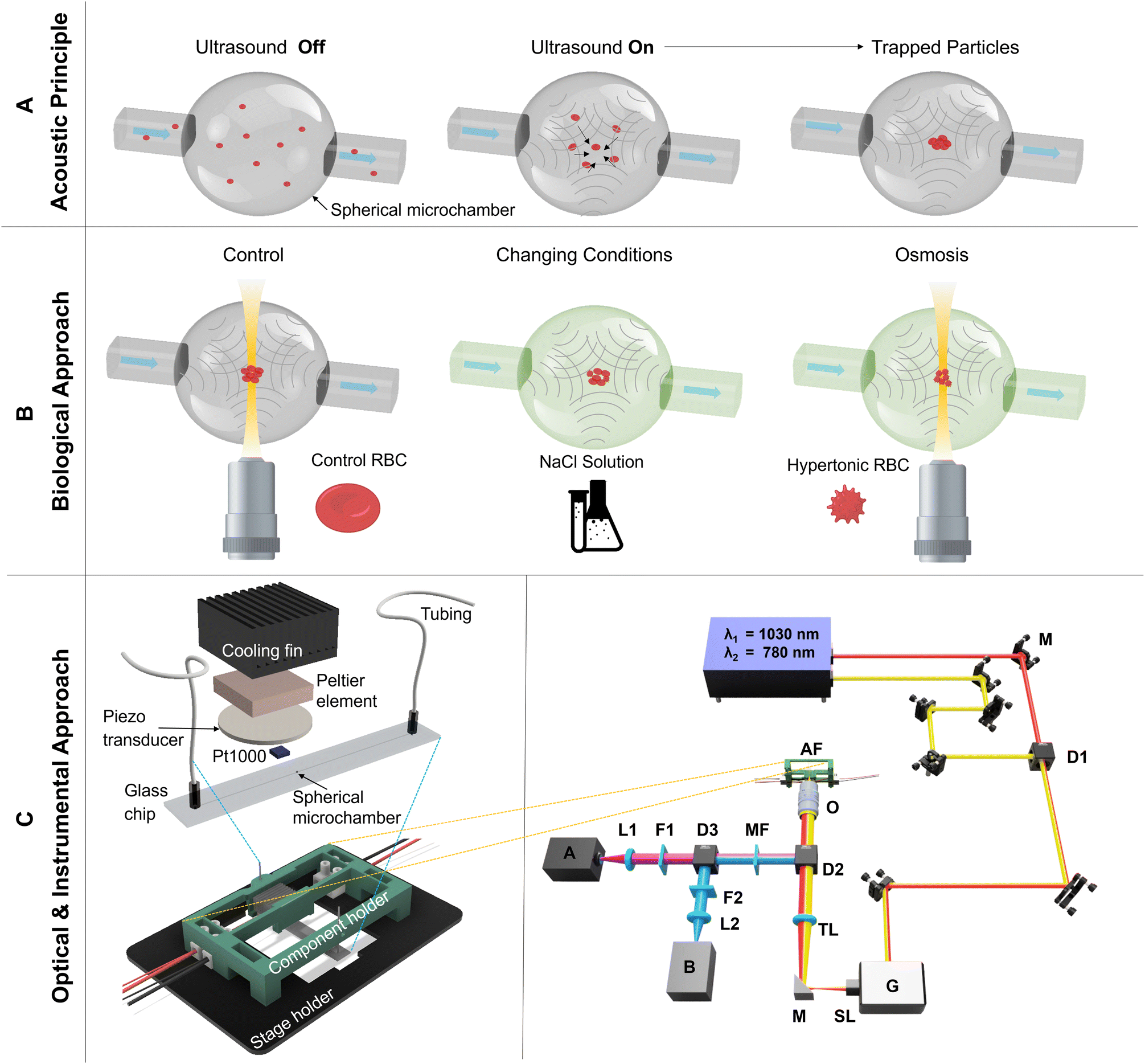 | ||
| Fig. 1 Concept and working principle of acoustofluidic platform technology and two-photon-excited fluorescence microscopy. A) The schematic shows the working principle for acoustophoretic trapping of particles in a spherical microchamber (SMC). The particles are homogeneously distributed in the SMC before the onset of the ultrasound. Directly after inducing an acoustic pressure field in the SMC (ultrasound on), the particles (acoustically hard material) start to migrate to areas of low pressure p = 0 due to the acoustic radiation force. In the presented SMC, the particles are moved into the center of the spherical cavity. B) Schematic of the biological approach using osmosis on red blood cells (RBC) in the SMC with visual analysis under the two-photon-excited fluorescence microscopy. C) The drawing of the acoustofluidic platform technology is shown on the left side, which includes the stage holder for the microscope and the component holder for the acoustic components. The acoustofluidic prototype consists of a glass chip with tubings, a piezo transducer for the acoustic actuation, and a PT1000 temperature sensor, Peltier element, and a cooling fin for the temperature control. A detailed schematic of the two-photon-excited fluorescence microscopy is shown on the right side. The laser-scanning approach is accomplished with a resonant-galvo scanner G working with 8 kHz and a laser source offering two wavelengths at λ1 = 1030 nm and λ2 = 780 nm. With two photomultiplier tubes (PMT) A and B as well as different filters F and dichroic mirrors D the generated fluorescence is separated from the excitation and detected. The acoustofluidic setup AF is mounted with different 3D printed parts above the used microscopy objective O. | ||
For the merging of the acoustofluidic trap with the multiphoton microscope, the former was adapted with 3D-printing parts to fit into the home-built optical setup based on a commercial microscope stand which is equipped with a resonant-galvo scanner and a piezo-driven objective for laser-scanning the sample in two lateral and one axial directions. A detailed description of the setup, as shown in Fig. 1 – C (right side), is given in section 5.1.
To illustrate these capabilities, the SMC was filled with a few 10 μm-sized trapped particles suspended in fluorescein-dextran solution. Subsequently, a z-stack of multiphoton xy-images was acquired to reconstruct this ensemble in 3D shown in Fig. 2. The solution and particles were recorded with different detection channels, spectrally separated by a dichroic mirror and appropriate bandpass filters (see 5.1). Quantitative analysis reveals the spatial dimensions of the SMC to be x = (547 ± 9) μm, y = (540 ± 9) μm, and z = (586 ± 9) μm as compared to the manufacturer's specified size of 550 μm in all dimensions. The position of one trapped particle closest to the SMC center is determined to x = (257 ± 3) μm, y = (279 ± 3) μm, and z = (318 ± 3) μm which is only slightly off-center by 6.42%, 4.78%, and 7.86% in the x-, y-, and z-direction, respectively.
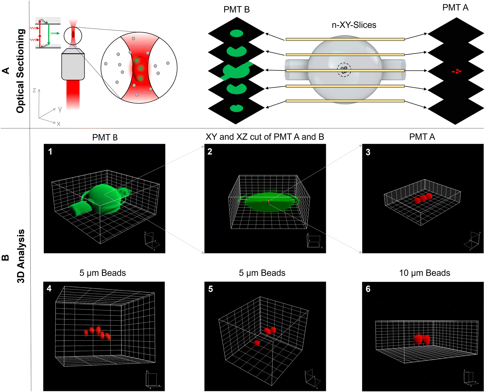 | ||
| Fig. 2 Three-dimensional particle analysis via the TPEFM. The schematic of the laser beam in the TPEFM and the optical sectioning in the SMC along the z-direction are presented in A). The detailed 3D analysis of the SMC by optically cutting through the cavity is demonstrated in B) 1–3. In images 4–6 3D images of beads with two different sizes were presented. | ||
It was not clear from the outset that the refraction occurring at the glass-solution interface of the SMC would not interfere with aberration-free high resolution imaging. However, the quantitative analysis suggests that minor aberrations do not alter the SMC's and individual particles' round shapes nor influence the magnification factor since the imaged shapes and sizes are determined correctly. Only a visible circumference surrounds the SMC in the vertical center plane, which is undoubtedly classified as a measurement artifact. Furthermore, the area in which imaging takes place is always the central zone. Consequently, the incoming wavefronts pass through this central sector of the SMC, a region where the spherically symmetrical shape leads to negligible refraction effects on the wavefronts. This minimal refraction preserves the accuracy of the imaging process. In cases where an attempt is made to image the entire SMC, aberrations can occur that affect the absolute measurement accuracy. To address these issues and increase measurement accuracy, additional investigations, including further empirical measurements or advanced optical simulations, should be performed.
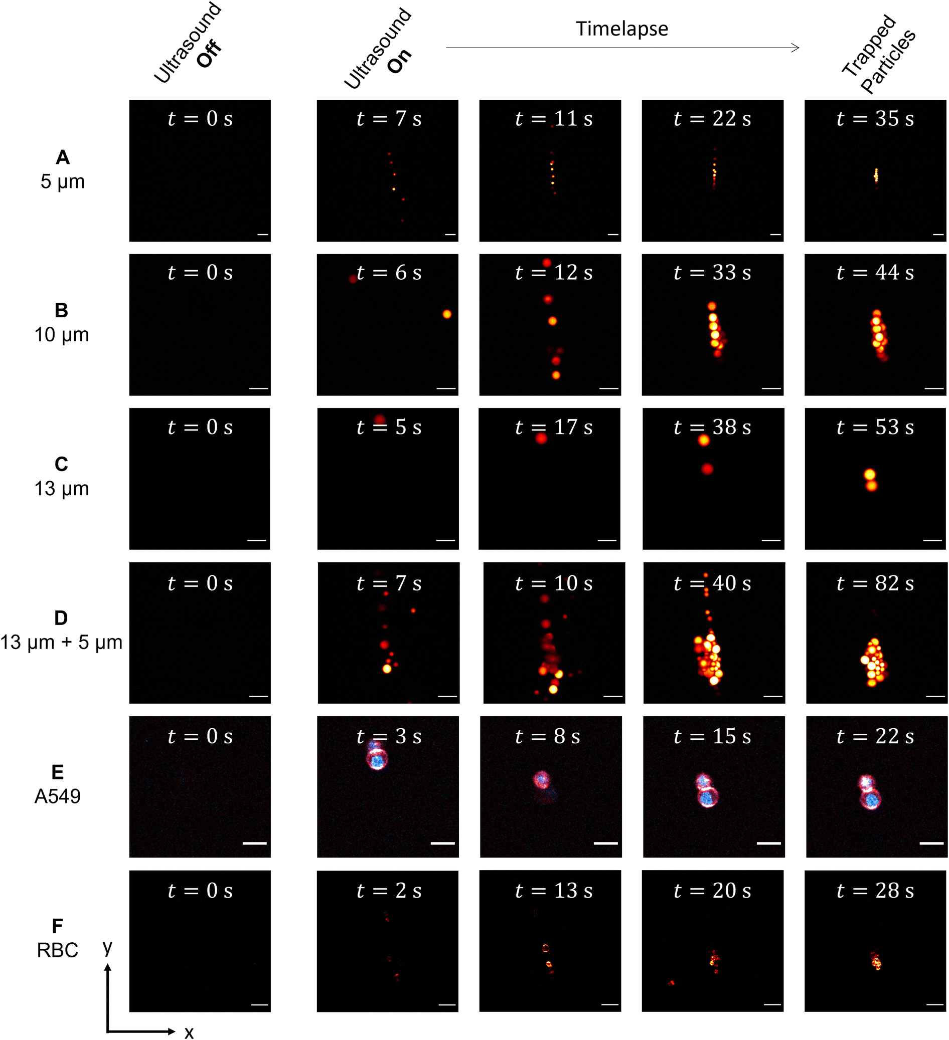 | ||
| Fig. 3 Acoustic particle trapping under the two-photon-excited fluorescence microscope. From A–D different particle sizes ranging from A) 5 μm, B) 10 μm, C) 13 μm and a mixture of D) 13 μm and 5 μm are displayed, in E) the time series of A549 cells and in F) of RBC cells are shown. Scale bar: 20 μm. | ||
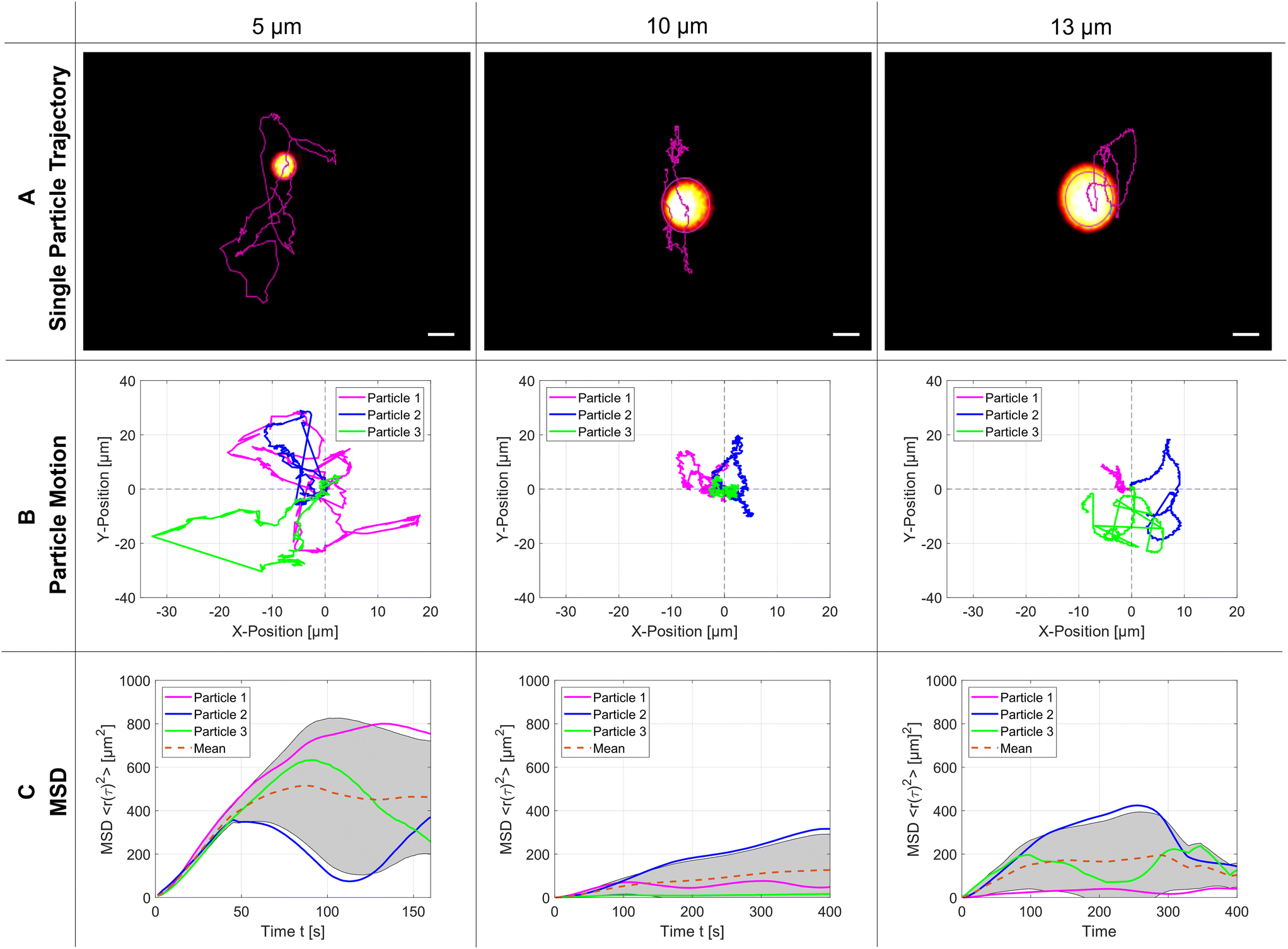 | ||
| Fig. 4 Motion of trapped particles. A) Particle trajectory for a single PS microparticle of diameter 5 μm, 10 μm, and 13 μm – scale bar: 5 μm. Three repetitions of the particle trajectories for each diameter are presented in B). In C), we demonstrate the calculated mean square displacement of the particles over time, respectively. | ||
Without statistical proof it can be directly seen that 5 μm particles occupy more space inside the SMC than the two bigger particles, which is a clear indication that the trapping force changes significantly with the particle size. From atomic force microscopy it is well-known that a more detailed analysis of the hindered Brownian motion could determine the strength of the trapping force but would be beyond the scope of this article.35 In panel (C), the calculated mean square displacement (MSD) is plotted over time: at the beginning it grows linearly. Still, it can later only reach a bound set by the finite size of the acoustic trap, which is significantly smaller than the dimensions of the SMC. The mean value for the plateaus of the MSD is reached at 500 μm2, 130 μm2, and 170 μm2 for the particle sizes of 5 μm, 10 μm and 13 μm, respectively. The acoustic parameters for every particle size are the modulated resonance frequency range f110 = 1.75–1.85 MHz and the peak-to-peak amplified amplitude Upp = 14.6 Vpp.
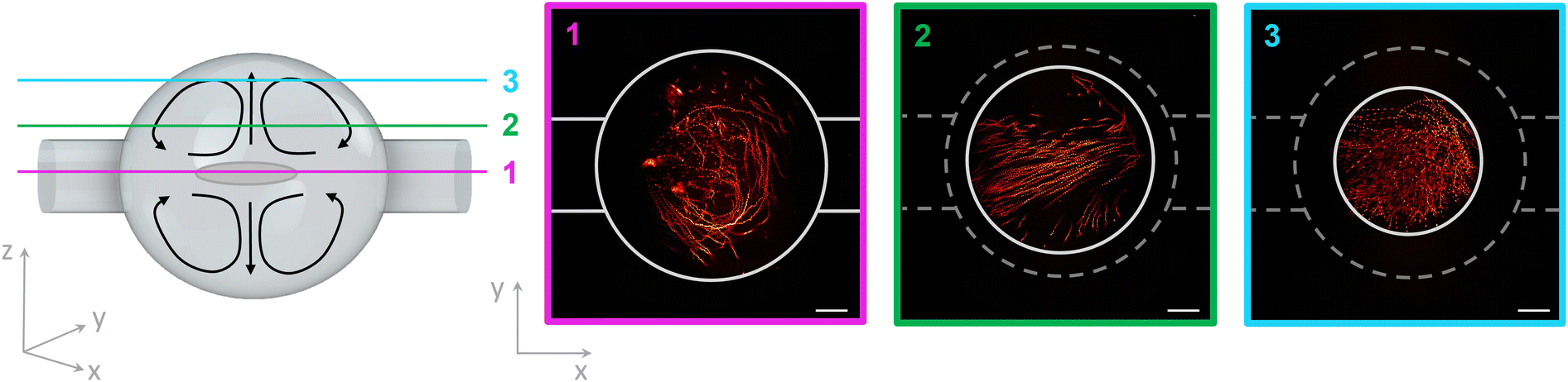 | ||
| Fig. 5 Acoustic streaming in the spherical microchamber. A sketch of the spherical microchamber with acoustic streaming is shown on the left side. The recorded layers 1–3 in xy-direction are marked in different colours. On the right side, the acoustic streaming of 1 μm microparticles is demonstrated for each layer in the SMC. Scale bar: 100 μm. | ||
2.3 Application to biology
| Membrane aspect ratio | Membrane major axis [μm] | Membrane minor axis [μm] | ||
|---|---|---|---|---|
| A549 membrane | Control | 0.96 ± 0.05 | 17.45 ± 1.44 | 16.71 ± 1.35 |
| Osmotic shock | 0.92 ± 0.08 | 13.66 ± 1.93 | 12.54 ± 1.98 | |
| Difference | 0.04 ± 0.09 | 3.79 ± 2.41 | 4.17 ± 2.40 | |
| Percentage | 4.17% | 21.72% | 24.96% |
| Nucleus aspect ratio | Nucleus major axis [μm] | Nucleus minor axis [μm] | ||
|---|---|---|---|---|
| A549 nucleus | Control | 0.87 ± 0.13 | 11.19 ± 1.48 | 9.65 ± 1.18 |
| Osmotic shock | 0.88 ± 0.10 | 9.87 ± 1.66 | 8.56 ± 1.18 | |
| Difference | −0.01 ± 0.16 | 1.32 ± 2.22 | 1.09 ± 1.67 | |
| Percentage | −0.44% | 11.80% | 11.30% |
| Aspect ratio | Major axis [μm] | Minor axis [μm] | ||
|---|---|---|---|---|
| RBC | Control | 0.91 ± 0.07 | 7.59 ± 1.04 | 6.87 ± 0.85 |
| Osmotic shock | 0.91 ± 0.07 | 5.71 ± 0.63 | 5.19 ± 0.57 | |
| Difference | 0.0 ± 0.1 | 1.88 ± 1.22 | 1.68 ± 1.02 | |
| Percentage | 0.00% | 24.77% | 24.45% |
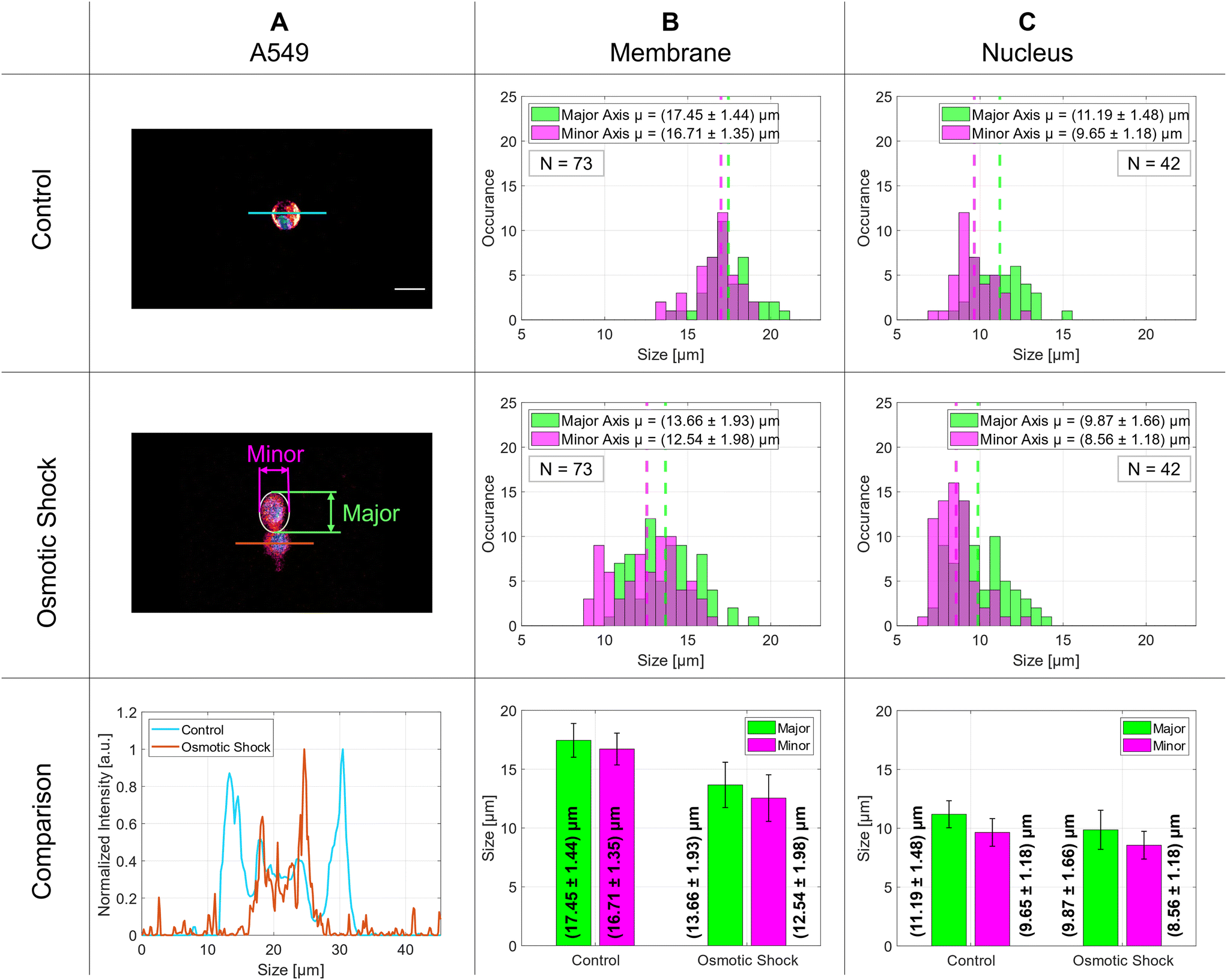 | ||
| Fig. 6 Demonstration of the osmotic shock in A549 lung cells. Column A displays representative microscopy images with a control cell in the first row and a cell post-osmotic shock in the second row. The third row provides a comparative analysis of intensity profiles derived from images in rows one and two. Column B illustrates the size distribution of the control group (first row) and cells after osmotic shock (second row), with a bar graph in the third row depicting mean values for the major (green) and minor (magenta) axes. The results for the nucleus are shown in C. Scale bar 20 μm. | ||
The distributions of 73 membrane and 42 nucleus diameters are presented in the histograms in columns B and C, respectively. The vertical dashed lines indicate the mean values of the Gaussian distributions. The membrane diameters change significantly by 4 μm for both major and minor axes and decrease from about 17 μm to 13 μm whereas the nucleus diameters stay nearly the same at around 10 μm with only a small change of about 1 μm. The exact numbers are given in Table 1. The aspect ratio for the control group implies a nearly round shape for the membrane that decreases slightly for cells after osmotic shock. Although the aspect ratio for the nucleus is still lower than for the membranes, it does not change after stimulus. The side-to-side comparison of an intensity profile of a typical control cell and a cell after osmotic shock is plotted in the last row of Fig. 6 on the left side and the above-mentioned diameter differences are illustrated with a bar graph to the right.
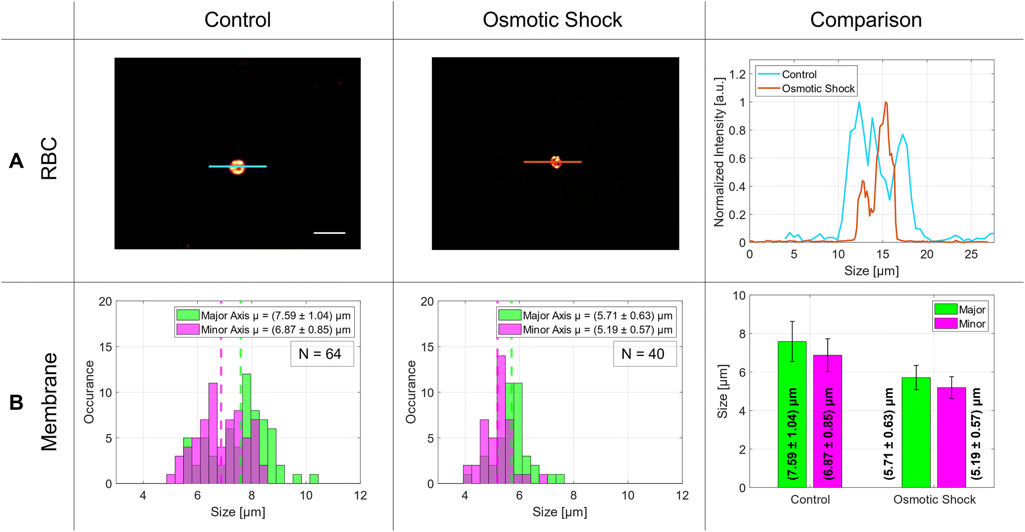 | ||
| Fig. 7 Statistical analysis of the osmotic shock in RBCs. Row A showcases two-photon microscopy images of control cells in the first column and cells subjected to osmotic shock displayed in the second column. The intensity line profile of both cells are shown in the third column. In row B, histograms demonstrate the size distributions of cells, accompanied by a bar graph in the far-right column, which highlights fluctuations in their mean values. Scale bar: 10 μm. | ||
The size distribution of the RBCs in the control group was around 7 μm with an aspect ratio of 0.91. In literature, the average size of a red blood cell is 7.5 μm in which our measurements are in good agreement.36 After osmotic shock, the diameters decreased significantly by 1.8 μm without changing the aspect ratio. The exact numbers are listed in Table 1 and visualized in the bar graph of Fig. 7 – comparison – B.
3 Discussion
3.1 3D analysis of acoustofluidic device
The TPEFM method enables the optical sectioning of trapped particles inside an SMC to reconstruct them in all three spatial dimensions, as seen in Fig. 2. The recorded image stacks allow for quantitative analysis of particle or living cell positions, sizes, shapes and some aspects of how well the acoustic trap is functioning. In our experiment, for example, the trap was not formed in perfect spherical shape but somewhat elongated along the x-axis. This could be attributed partly to the chamber's shape, which strongly influences the standing wave pattern of the acoustic trap. On the other hand, although great care was taken, we could not rule out completely that there was still a very small flow between the inlet and outlet of the chamber. In short, the 3D image analysis has the potential for in-depth investigation of cell clusters for biomedical research applications using this acoustofluidic device.3.2 Two-dimensional acoustic trapping of microparticles and human cells
As mentioned in the introduction, the acoustic particle trapping in a spherical microchamber is performed in the so-called mode (1, 1, 0), which leads to the accumulation of the particles in the center of the SMC.13,14 The evolving accumulation, which takes place after turning on the piezo actuators, is monitored as shown in the time series in Fig. 3A–F for different particle sizes as well as for labeled RBCs and A549 cells. Additionally, the TPEFM method delivers high resolution diffraction-limited images at video rate to classify different cell types and visualize compartments like membranes and nuclei.3.3 Mean squared displacement
The next experiment shows that the TPEFM method is capable of visualizing the particles themselves and delivering quantitative data about their dynamic motion. After the trap is established, the motion of the PS microparticles is governed by hindered diffusion. The imaging time series for the different-sized particles (5 μm, 10 μm, and 13 μm) reveal the exact positions of the individual particles over time. They are subsequently linked together by self-written code to produce a track of each, which can be further analyzed by determining the mean-square displacement of their diffusion. As shown in Fig. 4(C), the MSDs change with particle size, because the acoustic radiation force depends on the particle size (Frad ∝ a3) and differences in mass density and compressibility in relation to the suspending fluid.37 Therefore, the smaller the particle size with equal compressibility and density, the larger and faster their motion in the acoustic pressure field. Furthermore, the MSD increases linearly during the first few seconds due to the Brownian motion and reaches a plateau afterwards.38 This leads to the conclusion that an external force or confined barrier results from the acoustic trap responsible for the hindered diffusion. Careful inspection of the trajectories in Fig. 4(B) uncovered that the movement in the y-direction is more pronounced than in the x-direction due to the above-mentioned reasons (SMC roundness, backflow, etc.). For these experiments, the flow of the liquid was stopped. Consequently, the particles were subject only to Brownian motion and acoustic forces. Given that we consider the cavity to be perfectly round, we can approximate the diffusion as isotropic across all three spatial directions. However, for a more precise analysis, the diffusion must be considered as anisotropic due to inaccuracies within the chamber as well as a residual mass flow resulting from the remaining liquid flow.3.4 Acoustic streaming
Another effect in an acoustofluidic pressure field is the so-called acoustic streaming, which generates a steady flow or circulation of the fluid due to the viscous attenuation of the acoustic waves. The trapped cells in the SMC are surrounded by a nutrient medium and analytes. The circulation of the fluid caused by the streaming effect guarantees the mixing of the fluid medium and results in a homogeneous distribution of the nutrition and the analytes. This condition is very crucial for cell viability over the experimental period. The interaction between the sound waves and the fluid is well described in Bach et al.39 The acoustic streaming is dominant over the acoustic radiation force for fluid molecules and particles smaller than 1.4 μm.40 Wiklund et al. simulated the acoustic streaming patterns in a circular chamber. This we demonstrated experimentally as shown in Fig. 5.16 The 1 μm-sized particles move in so-called vortices inside the SMC, optically sectioned with our TPEFM method at three different layers inside the chamber to make the streaming trajectories thoroughly visible.3.5 Osmotic shock as biological application
The last experiment shows the applicability of the acoustofluidic trap in combination with the TPEFM method for biological applications such as the investigation of the osmotic effect on living cells. In this scenario, many advantages of our setup come into play, mainly the possibility (i) to make long-term observations (ii) under near in vivo conditions and (iii) to analyze the sample in 3D (iv) with high spatial and temporal resolution. We chose to study osmosis because it is part of many physiological processes and, therefore, a relevant topic for life science research. One of the major problems is that the osmotic active particles are only measured within samples bound to a surface – usually the glass surface of a cover slip. In contrast to this common procedure, the SMC enables us to investigate the osmotic effect on samples that are kept in the center of a chamber filled with fluid, preventing them from touching any surface. In this experiment we compared the diameter of trapped RBCs and A549 cells suspended in a phosphate-buffered saline solution (isotonic), and sodium chloride (hypertonic). The osmotic pressure of the isotonic solution equals the pressure inside the RBCs/A549 cells, so they do not undergo any chemical or physical transformations. However, the hypertonic medium has more effective osmotic pressure than the intracellular fluid. This results in a so-called net movement of the intracellular fluid through the semi-permeable cell membrane into the hypertonic medium. This leads to the visible shrinking of the cells that are reducing their volume by the fluid moving out.41,423.6 A549 cells
The osmotic response was examined for A549 cells suspended in a medium as shown in the results section in Fig. 6 and Table 1. The use of the SMC makes it easy to analyze the size of the living cells in real-time and to increase their number arbitrarily to improve the statistical analysis. In the analysis of the cellular components, we observed a notable reduction in the dimensions of the membrane's axes after changing the isotonic medium into a hypertonic medium. Specifically, the major axis diminished from an initial size of 17.45 μm by (3.79 ± 2.41) μm, signifying an average contraction of 21.72%. Similarly, the minor axis exhibited a reduction from the initial length of 16.71 μm by (4.17 ± 2.40) μm, relating to an average decrease of 24.96%. Furthermore, the nuclear dimensions also displayed a decrease. The major axis of the nucleus, starting at 11.19 μm, shrank by 11.80%, corresponding to a change of (1.32 ± 2.22) μm. The minor axis of the nucleus, starting at a size of 9.65 μm, decreased by 11.30%, with an absolute change of (1.09 ± 1.67) μm. The membrane diameter decreases significantly under osmotic shock whereas the nucleus diameter shows a much smaller effect. This compares well with what is reported in literature for A549 cells.43 The elevated standard deviations observed in the nucleus measurements can be attributed to the inherent variability in nuclear morphology; the cell nucleus cannot be assumed to be perfectly spherical. Depending on the cell type and its physiological state, the nuclear shape may undergo significant transformations, resulting in irregular configurations.443.7 Red blood cells
The same experiment was repeated with living red blood cells. As can be seen in Fig. 7 and in Table 1, the RBC reduces its average diameter by (1.88 ± 1.21) μm in the major axis and by (1.68 ± 1.02) μm in the minor axis. The absolute diameter of the major axis was 7.6 μm on average and diminished to 5.7 μm under osmotic shock. In literature, the osmotic response was measured with the help of optical tweezers avoiding the interaction with a surface as well. There, the RBCs changed their size from around 9.8 μm to 8.0 μm.45 Similar results were obtained by Gautam et al., where they observed a diameter change from 8.0 μm to 6.4 μm using another measurement method.46 This shows that our results fit well with the former ones. In summary, the application of our new device to biological problems seems to work very well and demonstrates that the A549 cells, as well as the RBCs, are studied under healthy conditions, and our analysis method works well for this kind of investigation.4 Conclusion
This article presents two- and three-dimensional acoustic particle trapping experiments under a two-photon-excited fluorescence microscope. The TPEFM allows for sensitive verification of particle position and motion in the acoustic trap and chamber dimensions in 3D by optical sectioning. Likewise, the acoustic streaming effects on small particles in the SMC were demonstrated for multiple cavity layers. As a biological example of combining the acoustofluidic platform technology with the TPEFM method, we performed the osmosis on RBCs and lung cells (A549). This biological approach is a potential biomedical in vitro research application working close to in vivo conditions for sensitive analysis of cell functions and cell–cell interactions.To fully harness the wide range of benefits offered by the TPEFM technique, future efforts will focus on applying this framework to spheroids or larger biological aggregates over extended time scales. Following successful integration with these samples, the technique may be further refined and potentially serve as a viable alternative to animal testing.
5 Methods
5.1 Two-photon microscopy setup
For diffraction-limited 3D images of the SMC and its function, a homebuilt TPEFM setup was used (Fig. 1 – C-right). As an excitation source, an ultrashort laser pulse system with two wavelengths λ1 = 1030 nm and λ2 = 780 nm (FemtoFiber Dichro Design, TOPTICA Photonics AG) was employed. Both lasers provide a maximal power of 100 mW with 80 fs pulses at a repetition rate of 80 MHz. The two beams were overlayed with the help of different mirrors (see Fig. 1 labeled as M) and a dichroic mirror D1 (F38-825, AHF Analysentechnik). After the beams were superimposed, they reached a resonant-galvo scanner system G (Multiphoton Essential Kit, Thorlabs) for laser scanning. The systems runs at 8 kHz and delivers 31 frames per second with an image size of (1024 × 1024) pixels. With a telecentric system consisting of the scan lens SL and tube lens TL, the beams were coupled into a 20× Nikon water immersion objective O (CFI Apo MRD77200, Nikon) with a NA of 0.95 and a working distance of 0.9–0.99 mm. The point spread function was measured with 200 nm fluorescent nanobeads (F8806, ThermoFisher) and resulted to a lateral resolution of 443 nm and an axial resolution of 1.13 μm inside the SMC. With the help of a 3D printed stage adapter, the acoustofluidic setup (AF) was mounted on a xyz-stage (TI2-S-SE-E, Nikon). The fluorescence was collected with the same objective lens in epi-direction. A dichroic mirror D2 (FF825-sDi01, Laser2000) separates the excitation light from the fluorescence light, and with two InGaAsP photomultiplier tubes (Multiphoton Essential Kit, Thorlabs) labeled as A and B it is quantified in a non-descanned configuration. Another dichroic mirror D3 in the detection path separates the light with individual filters into a red F1 (AT 600 LP, AHF Analysentechnik) for PMT A and blue F2 (F76-594, AHF Analysentechnik) spectral emission range for PMT B. With two lenses, L1 and L2, the fluorescence photons are focused on the detection area of the PMTs. Two multiphoton filters MF (F39-745, AHF Analysentechnik) block out scattered excitation light to improve the signal-to-noise ratio. To obtain 3D datasets, the microscope stage was synchronized with the scanner system and the detectors. The experiment as a whole was controlled by a self-written NIS-program.5.2 Acoustofluidic platform
The acoustofluidic platform consists of a microfluidic chip, an acoustic drive unit with an automated temperature control, and a microfluidic control unit for automated injection of microparticles/cells and media as seen in Fig. 1 (C left part). The microfluidic glass chip (70 × 10 × 0.6) mm3 consists of a wet-etched 500 μm diameter spherical microchamber (SMC, nearly perfect sphere with 15–20% deviation) with straight inlet and outlet channels with cross-section 150 μm × 150 μm. The chips were fabricated by IMT Masken und Teilungen AG (Switzerland). The fabrication includes the etching process of two hemispherical chambers and the bonding to a microfluidic chip. The channel inlet and outlet are connected with tubing attached and sealed via super- and silicone glue. The tubing was connected to a pressure-based flow control through a valve system for achieving automated microfluidic control. A 2 MHz piezo transducer was fixed to the glass chip using super glue to generate the acoustic pressure field in the SMC. To trap the particles in the mode (1, 1, 0), the piezo transducer was excited with frequency modulated frequency f110 from 1.75 to 1.85 MHz with a modulation rate of 14.6 Hz and an amplitude Upp = 14.6 Vpp. The mode shape (1, 1, 0) results from the calculation of the Helmholtz wave equation ∇2p + k2p = 0 (ref. 8) with pressure p and wave number k in spherical coordinates (r, θ, ϕ) which is given by the pressure field p(r, θ, ϕ) = R(r)Θ(θ)Φ(ϕ), where r describes the radial and θ and ϕ the angular parts of the equation. The detailed calculation of the mode shapes in a spherical cavity can be seen in Russell.47 The resulting notation (n, l, m) describes the number of nodal surfaces in a spherical cavity. For trapping particles in the center of the SMC, we need the lowest degenerate pair of modes which results in (1, 1, 0). The temperature control consists of a temperature sensor, a Peltier element Pt1000 (M222, Heraeus Nexensos), and an aluminum cooling fin. As seen in Fig. 1-C, all components are implemented in a self-designed and 3D printed holder plugged into a 3D printed stage holder. The stage holder can be easily modified for every type of microscope.5.3 Microparticles and fluorescent dye
![[thin space (1/6-em)]](https://www.rsc.org/images/entities/char_2009.gif) 000 Da, Sigma-Aldrich) in 5 mL PBS was mixed and vortexed. The 780 nm laser was used for the excitation, and the fluorescence signal was detected with PMT B.
000 Da, Sigma-Aldrich) in 5 mL PBS was mixed and vortexed. The 780 nm laser was used for the excitation, and the fluorescence signal was detected with PMT B.
5.4 Cell lines and medium
:6 in T175 cell culture flasks (83.3912.002, Sarstedt AG und Co.).
5.5 Immunostaining
:1000 dilution) including the desired cell type. After a 30-minute-incubation-time at 37 °C and 5% CO2 the cells were ready for the nucleus stain or the imaging procedure. The excitation maximum wavelength of the Flipper-TR is at 480 nm, therefore the 1030 nm laser was used for the excitation and PMT A for detection.
:2000 dilution of a 1 mM stock solution of Hoechst (62249, Thermo Fisher Scientific Inc.) and the cell medium was prepared. Like the cell membrane stain, the solution was given 30 min time to incubate at 37 °C and 5% CO2. The fluorescence signal was observed with PMT B after excitation with a wavelength of 780 nm.
5.6 Image analysis
To calculate a displacement trajectory of the trapped objects, a self-written Matlab code based on the Fiji plugin TrackMate was used.49 From the obtained position and experiment information the pathwise mean square displacements were calculated according to eqn (1):
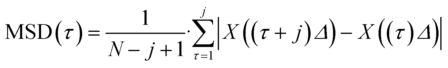 | (1) |
Institutional Review Board statement
This study (620/21 S-KK) was approved by Ethikkommission an der Technischen Hochschule München, approved on 26 October 2021.Author contributions
T. K., B. S., T. H. and O. H. conceived the experiments, T. K. and B. S. conducted the experiments, T. K., B. S., P. B., T. H., R. B. analysed the results. All authors reviewed the manuscript.Conflicts of interest
There are no conflicts to declare.Acknowledgements
This work was supported by the Bavarian Academic Forum (Bay-WISS) – Joint Academic Partnership ‘Health’ and was funded by the Bavarian State Ministry of Science and the Arts and by LaKoF Bayern – State Conference of Women's and Equal Opportunity Representatives at Bavarian Universities. This work was financially supported by the Munich University of Applied Sciences HM and the German Research Foundation (DFG) through the “Open Access Publication Costs (NE 1911/2-1)” program. Furthermore, we want to thank Dr. Stefanie Kiderlen and Dr. Lukas Krainer who supported our preliminary work with their demo TPEFM device. We are grateful to Franka Schulz, who performed the results for the osmolarity measurements.References
- D. Furman, J. Campisi, E. Verdin, P. Carrera-Bastos, S. Targ, C. Franceschi, L. Ferrucci, D. W. Gilroy, A. Fasano and G. W. Miller, et al. , Nat. Med., 2019, 25, 1822–1832 CrossRef CAS.
- P. K. Chattopadhyay, T. M. Gierahn, M. Roederer and J. C. Love, Nat. Immunol., 2014, 15, 128–135 CrossRef CAS.
- J. Rodrigues, M. A. Heinrich, L. M. Teixeira and J. Prakash, Trends Cancer, 2021, 7, 249–264 CrossRef CAS.
- K. M. McKinnon, Curr. Protoc. Immunol., 2018, 120 DOI:10.1002/cpim.40.
- A. Adan, G. Alizada, Y. Kiraz, Y. Baran and A. Nalbant, Crit. Rev. Biotechnol., 2017, 37, 163–176 CrossRef CAS.
- M. B. Bracken, J. R. Soc. Med., 2009, 102, 120–122 CrossRef.
- A. E. Sorour, J. Lönn, S. S. Nakka, T. Nayeri and F. Nayeri, Cytokine, 2015, 71, 8–15 CrossRef CAS.
- H. Bruus, Theoretical Microfluidics, Oxford University Press, vol. 18, 2008 Search PubMed.
- P. Augustsson, R. Barnkob, S. T. Wereley, H. Bruus and T. Laurell, Lab Chip, 2011, 11, 4152–4164 RSC.
- M. Wu, C. Chen, Z. Wang, H. Bachman, Y. Ouyang, P.-H. Huang, Y. Sadovsky and T. J. Huang, Lab Chip, 2019, 19, 1174–1182 RSC.
- B. Kang, J. Shin, H.-J. Park, C. Rhyou, D. Kang, S.-J. Lee, Y.-s. Yoon, S.-W. Cho and H. Lee, Nat. Commun., 2018, 9, 5402 CrossRef CAS.
- Z. Ao, Z. Wu, H. Cai, L. Hu, X. Li, C. Kaurich, J. Chang, M. Gu, L. Cheng and X. Lu, et al. , Adv. Sci., 2022, 9, 2201478 CrossRef CAS.
- B. Sailer, R. Barnkob and O. Hayden, Acoustofludics 2020, Virtual Conference, 2020, Abstract No. 0077.
- B. Sailer, R. Barnkob and O. Hayden, MicroTAS 2020, Virtual Conference, 2020, Abstract No. 3029.
- K. Olofsson, V. Carannante, M. Ohlin, T. Frisk, K. Kushiro, M. Takai, A. Lundqvist, B. Önfelt and M. Wiklund, Lab Chip, 2018, 18, 2466–2476 RSC.
- M. Wiklund, H. Brismar and B. Önfelt, Lab Chip, 2012, 12, 3221–3234 RSC.
- J. Novotny, A. Lenshof and T. Laurell, Electrophoresis, 2022, 43, 804–818 CrossRef CAS.
- H. D. Santos, A. E. Silva, G. C. Silva, E. B. Lima, A. S. Marques, M. S. Alexandre-Moreira, A. C. Queiroz, C. Jacinto, J. Henrique Lopes and U. Rocha, et al. , Adv. Eng. Mater., 2021, 23, 2100552 CrossRef CAS.
- V. Charwat, K. Schütze, W. Holnthoner, A. Lavrentieva, R. Gangnus, P. Hofbauer, C. Hoffmann, B. Angres and C. Kasper, J. Biotechnol., 2015, 205, 70–81 CrossRef CAS.
- W. Denk, J. H. Strickler and W. W. Webb, Science, 1990, 248, 73–76 CrossRef CAS.
- W. R. Zipfel, R. M. Williams and W. W. Webb, Nat. Biotechnol., 2003, 21, 1369–1377 CrossRef CAS.
- P. T. So, C. Y. Dong, B. R. Masters and K. M. Berland, Annu. Rev. Biomed. Eng., 2000, 2, 399–429 CrossRef CAS.
- R. R. Anderson and J. A. Parrish, J. Invest. Dermatol., 1981, 77, 13–19 CrossRef CAS.
- M. Göppert-Mayer, Ann. Phys., 1931, 401, 273–294 CrossRef.
- P. Hänninen, A. Soini, N. Meltola, J. Soini, J. Soukka and E. Soini, Nat. Biotechnol., 2000, 18, 548–550 CrossRef.
- A. D. Elliott, Curr. Protoc. Cytom., 2020, 92, e68 CrossRef.
- C. Gomez-Cruz, S. Laguna, A. Bachiller-Pulido, C. Quilez, M. Cañadas-Ortega, I. Albert-Smet, J. Ripoll and A. Muñoz-Barrutia, Biosensors, 2022, 12, 1110 CrossRef CAS.
- J. Huisken and D. Y. Stainier, Development, 2009, 136, 1963 CrossRef CAS.
- P. Luu, S. E. Fraser and F. Schneider, Commun. Biol., 2024, 7, 364 CrossRef.
- M. Rubart, Circ. Res., 2004, 95, 1154–1166 CAS.
- K. W. Dunn and P. A. Young, Nephron Exp. Nephrol., 2006, 103, e33–e40 Search PubMed.
- J. Jonkman, C. M. Brown, G. D. Wright, K. I. Anderson and A. J. North, Nat. Protoc., 2020, 15, 1585–1611 CrossRef CAS.
- B. Yang, M. Lange, A. Millett-Sikking, X. Zhao, J. Bragantini, S. VijayKumar, M. Kamb, R. Gómez-Sjöberg, A. C. Solak and W. Wang, et al. , Nat. Methods, 2022, 19, 461–469 CrossRef CAS.
- W. Qiu, H. Bruus and P. Augustsson, Phys. Rev. E, 2020, 102, 013108 CrossRef CAS.
- T. Li and M. G. Raizen, Ann. Phys., 2013, 525, 281–295 CrossRef CAS.
- M. Diez-Silva, M. Dao, J. Han, C.-T. Lim and S. Suresh, MRS Bull., 2010, 35, 382–388 CrossRef CAS.
- H. Bruus, Lab Chip, 2012, 12, 1014–1021 RSC.
- M. J. Saxton, Biophys. J., 2007, 92, 1178–1191 CrossRef CAS.
- J. S. Bach and H. Bruus, Phys. Rev. E, 2019, 100, 023104 CrossRef CAS.
- R. Barnkob, P. Augustsson, T. Laurell and H. Bruus, Phys. Rev. E: Stat., Nonlinear, Soft Matter Phys., 2012, 86, 056307 CrossRef.
- M. Rasouli, Clin. Biochem., 2016, 49, 936–941 CrossRef CAS.
- L. K. Goodhead and F. M. MacMillan, Adv. Physiol. Educ., 2017, 41, 298–305 CrossRef.
- P. D'Angelo, G. Tarabella, A. Romeo, A. Giodice, S. Marasso, M. Cocuzza, F. Ravanetti, A. Cacchioli, P. G. Petronini and S. Iannotta, MRS Commun., 2017, 7, 229–235 CrossRef.
- A. Sneider, J. Hah, D. Wirtz and D.-H. Kim, Cell Adhes. Migr., 2019, 13, 50–62 CrossRef CAS.
- Y. Liang, G. Liang, Y. Xiang, J. Lamstein, R. Gautam, A. Bezryadina and Z. Chen, Phys. Rev. Appl., 2019, 12, 064060 CrossRef CAS.
- R. Gautam, Y. Xiang, J. Lamstein, Y. Liang, A. Bezryadina, G. Liang, T. Hansson, B. Wetzel, D. Preece and A. White, et al. , Light: Sci. Appl., 2019, 8, 31 CrossRef.
- D. A. Russell, Am. J. Phys., 2010, 78, 549–554 CrossRef.
- J. Schindelin, I. Arganda-Carreras, E. Frise, V. Kaynig, M. Longair, T. Pietzsch, S. Preibisch, C. Rueden, S. Saalfeld and B. Schmid, et al. , Nat. Methods, 2012, 9, 676–682 CrossRef CAS.
- J.-Y. Tinevez, N. Perry, J. Schindelin, G. M. Hoopes, G. D. Reynolds, E. Laplantine, S. Y. Bednarek, S. L. Shorte and K. W. Eliceiri, Methods, 2017, 115, 80–90 CrossRef CAS.
Footnote |
| † These authors contributed equally to this work. |
| This journal is © The Royal Society of Chemistry 2024 |