
 Open Access Article
 This Open Access Article is licensed under a Creative Commons Attribution-Non Commercial 3.0 Unported Licence
Flexoelectricity in hydroxyapatite for the enhanced piezocatalytic degradation of phenanthrene in soil†
Jun
Han
,
Wenrou
Tian
,
Ye
Miao
,
Najun
Li
 *,
Dongyun
Chen
,
Qingfeng
Xu
,
Hua
Li
and
Jianmei
Lu
*
*,
Dongyun
Chen
,
Qingfeng
Xu
,
Hua
Li
and
Jianmei
Lu
*
College of Chemistry, Chemical Engineering and Materials Science, Collaborative Innovation Center of Suzhou Nano Science and Technology, Soochow University, Suzhou 215123, China. E-mail: linajun@suda.edu.cn; lujm@suda.edu.cn
First published on 11th October 2023
Abstract
Coupling the effects of flexoelectricity with piezoelectricity has been proved to effectively harvest mechanical energy. In this study, a composition-graded core–shell structure (HAP@FAP) was prepared by surface-gradient F-doping in hydroxyapatite, which could introduce flexoelectricity by a built-in strain gradient. A flexoelectric-boosted piezoelectric response was demonstrated by piezoresponse force microscopy (PFM) characterization, showing that the piezoelectric constant of HAP@FAP was increased by 2.25 times via a lattice strain gradient induced by chemical heterogeneities derived from the unique composition-graded core–shell structure. Thus, the piezocatalytic activity of HAP@FAP for phenanthrene (PHE) degradation in soil was enhanced. This work provides a new strategy for the modification of piezoelectric catalysts for the remediation of organics-contaminated soils on industrial land.
Keywords: Hydroxyapatite; Flexoelectricity; Piezocatalysis; Gradient doping; Soil remediation.
1 Introduction
Soil contamination is defined as the deterioration of soil function attributed to high pollutant concentration in the soil. With the development of industrialization and agriculture, pollutants in soil are accumulating, which consequently has become a severe environmental problem. Polycyclic aromatic hydrocarbons (PAHs) as typical persistent organic pollutants have been recognized as primary soil pollutants due to their high hydrophobicity, toxicity, and structural stability.1–5 It is imperative to develop effective methods to remove the remaining PAHs from contaminated soil environments. Various treatment processes (e.g. natural decay, bioremediation, electric technology, and adsorption6–8) have been used to eliminate PAHs from soil. However, the removal efficiency of these methods is still too low to fulfil practical requirements, owing to the slow desorption of pollutants and poor mass transfer in heterogeneous systems. Recently, the ultrasonic dispersion method has been proved to be an efficient approach to enhance the desorption of pollutants9–11 and accelerate mass transfer (especially in soil systems).12 Besides, it is worth noting that the quenching of numerous cavitation bubbles could generate a pressure of up to 108 Pa,13 which would make it possible to degrade PAHs in soil via piezocatalysis technology.Piezoelectric materials, a type of efficient catalysts, can convert external mechanical energy into chemical energy.14,15 Under external force, charge carriers can be separated and migrated to the surface of the catalysts driven by the built-in piezoelectric field, which can react with water, oxygen, and other substances to generate reactive free radicals.16,17 Hydroxyapatite (Ca10(PO4)6(OH)2, HAP), an emerging piezoelectric material, has exhibited broad application prospects in the treatment of pollutants in gas, liquid, and solid phases due to its various advantages, including good biocompatibility, controllable morphology, ion-exchange capability, acid–base adjustability, and wide range of sources.18–20 However, the weak piezoelectric coefficient (d33) of HAP (1–16 pm V−1)21 has hindered its further application in piezocatalysis. As a strategy that can directly affect the piezoelectric response, the coupling effect of piezoelectricity and flexoelectricity has been applied to prepare piezoelectric materials with a high piezoelectric coefficient.22 Here, piezoelectricity is based on electric polarization caused by uniform strain, while flexoelectricity refers to polarization caused by a strain gradient.23,24 Due to the very weak atomic strain gradient in bulk dielectric materials, the flexoelectricity in these materials is basically negligible. However, the flexoelectric effect in nanomaterials can be manifested because the magnitude of the strain gradient is inversely proportional to the size of the nanostructure.
In this study, a unique composition-graded core–shell structure is reported, which could induce flexoelectricity by a built-in strain gradient. Hydroxyapatite@fluorapatite core–shell nanorods (HAP@FAP) were prepared via ion exchange, which actually led to gradient F-doping in the hydroxyapatite (Fig. 1). Owing to the differences in the lattice parameters between the crystal structure of HAP and FAP, the concentration-graded FAP shell layer uniformly formed on the surface of the HAP core could induce a strain gradient in the core-to-surface direction. Thus, this nanoscale strain gradient could induce a flexoelectric effect, thereby boosting the piezoelectric response of HAP@FAP. In addition, the unique effect of the composition-graded core–shell structure was further demonstrated by F(1.5)-HAP as a comparison without gradient F-doping, which was prepared by directly adding NaF into the precursor solution with the ratio of n(Ca)![[thin space (1/6-em)]](https://www.rsc.org/images/entities/char_2009.gif) :n(F) = 10:1.5. The increment of the piezoelectric coefficient (d33) was monitored by piezoelectric response force microscopy (PFM), reflecting that the piezoelectric response was enhanced. Finally, HAP@FAP was applied to the piezocatalytic degradation of the persistent organic pollutant phenanthrene (PHE) in soil. Meanwhile, the factors that may affect the piezocatalytic activity were also systematically investigated.
:n(F) = 10:1.5. The increment of the piezoelectric coefficient (d33) was monitored by piezoelectric response force microscopy (PFM), reflecting that the piezoelectric response was enhanced. Finally, HAP@FAP was applied to the piezocatalytic degradation of the persistent organic pollutant phenanthrene (PHE) in soil. Meanwhile, the factors that may affect the piezocatalytic activity were also systematically investigated.
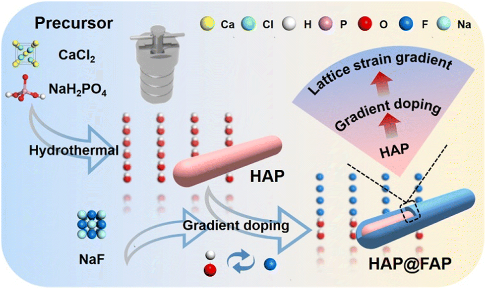 | ||
| Fig. 1 Schematic illustration of the fabrication of HAP@FAP. | ||
2 Results and discussion
2.1 Morphology and microstructure
The scanning electron microscopy (SEM) images showed that the pristine HAP exhibited a relatively uniform nanorod morphology, and the HAP@FAP-x prepared by surface-gradient F-doping (Fig. S3† and 2b) showed a similar morphology. However, the morphology of the F(1.5)-HAP solid-solution nanocrystals changed from nanorod to a hexagonal prism (Fig. 2c). The energy-dispersive X-ray spectroscopy (EDX) mapping images (Fig. S4†) showed the uniform distribution of Ca, P, O, and F elements in HAP@FAP-x and F(1.5)-HAP, demonstrating the successful introduction of F−. In addition, the lattice distributions of the as-prepared samples were further observed by high-resolution transmission electron microscopy (HRTEM). Clear and ordered lattice fringes were observed: the lattice spacings of 0.343 nm (Fig. 2d), 0.345 nm (Fig. 2e), and 0.344 nm (Fig. 2f) all corresponded to the (002) crystal faces of HAP.25 Since the crystal structures of HAP and FAP were almost identical on the (002) crystal face, no significant changes in the lattice spacing between these samples could be observed.26,27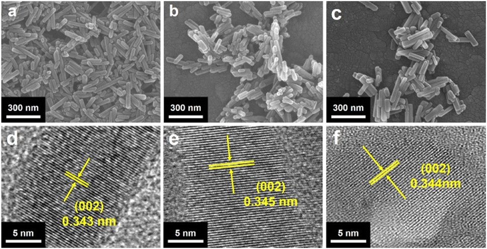 | ||
| Fig. 2 SEM images of (a) HAP, (b) HAP@FAP-1.5, and (c) F(1.5)-HAP. HRTEM images of (d) HAP, (e) HAP@FAP-1.5, and (f) F(1.5)-HAP. | ||
The crystal structure of the catalysts was further studied by X-ray diffraction (XRD). As shown in Fig. 3a, the diffraction peak of HAP nanorod corresponded to the hexagonal phase of HAP (JCPDS No. 09-0432). The diffraction peaks at 25.88°, 31.77°, 32.20°, 32.90°, and 34.05° were assigned to the (002), (211), (112), (300), and (202) crystal planes of HAP, respectively. The HAP@FAP-x with a core–shell structure showed an XRD pattern similar to that of the pristine HAP (Fig. S5†). However, as the value of x increased, the diffraction peaks of HAP@FAP-x gradually shifted to higher angles, owing to the formation of more FAP in the superficial crystal structure of HAP through the gradient F-doping. The F(1.5)-HAP did not show new diffraction peaks, but displayed a more significant shift compared with HAP (Fig. 3b), indicating that F(1.5)-HAP was not a mixed phase of HAP and FAP, but rather a solid-solution structure.28 It is worth noting that the (311) and (112) crystal planes of F(1.5)-HAP were shifted to higher angles and the intensity of the two diffraction peaks also decreased.29 In addition, the spacing between the two crystal facets was also significantly shortened. All these changes arose from the introduction of F− (133 pm), whose ionic radius was smaller than that of OH− (137 pm), resulting in lattice distortion.
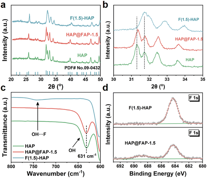 | ||
| Fig. 3 (a) The XRD patterns of HAP, HAP@FAP-1.5, and F(1.5)-HAP; (b) enlarged view between 30–35°; (c) FTIR scans of HAP, HAP@FAP-1.5, and F(1.5)-HAP; and (d) F 1s high-resolution XPS spectra of HAP@FAP-1.5 and F(1.5)-HAP. | ||
To further distinguish the heterogeneous core–shell and solid-solution structure, FTIR and XPS analyses were executed. As shown in Fig. 3c, pristine HAP and HAP@FAP-1.5 exhibited a distinct hydroxyl signal peak at 631 cm−1 derived from the hydroxyl group, while F(1.5)-HAP did not. Instead, a new vibration peak appeared between 700–800 cm−1, corresponding to the hydrogen bonding between F− and OH− in F(1.5)-HAP.30 The FTIR results showed that only part of the OH− in the superficial layer was replaced by F− in HAP@FAP-1.5, while the deeper core still maintained the crystal structure of HAP. On the contrary, most of the OH− in F(1.5)-HAP was replaced by F−, forming a Ca10(PO4)6(OH)1−xFx solid-solution structure. Fig. 3d also shows that the core–shell structure had a lower F content than that of F(1.5)-HAP.
This could also be attributed to the fact that F− could hardly reach the nuclear layer of HAP through the ion-exchange reaction. Likely, according to Table S2 and Fig. S6,† the atomic ratio of F and Ca in HAP@FAP-x gradually increased with the increasing NaF concentration. However, when x > 1, the F:Ca atomic ratio was significantly lower than the feeding ratio of the F source and Ca sources, forcefully demonstrating that OH− in the deeper core structure could hardly be replaced by F− through the ion-exchange method. In contrast, in the F(1.5)-HAP solid-solution structure prepared by the hydrothermal reaction, the F:Ca atomic ratio could basically match the feeding ratio (0.15:1).
Hence, HAP@FAP-1.5 was demonstrated to be not just a simple core–shell structure, but a composition-graded core–shell structure resulting from the Kirkendall effect,22,31,32 with the simultaneous interdiffusion of F− and OH−. F− diffused along the shell–core direction and constantly substituted OH−, thus uniformly forming the concentration-graded FAP shell on the surface of the HAP core.33 In addition, no obvious phase boundary between FAP and HAP could be observed. The difference in the radius of F− and OH− led to the change in the lattice parameters in the shell layer of HAP@FAP-x, resulting in electric polarization (i.e., flexoelectricity) triggered by the strain gradient, apart from the piezoelectric effect of HAP itself.
2.2 Piezoelectric response and current
To demonstrate the piezoelectricity of HAP@FAP-1.5 intuitively, piezoresponse force microscopy (PFM) was used to detect its piezoelectric response. Fig. 4a shows the stacked nanoparticles morphology of HAP@FAP-1.5, and the corresponding piezoelectric response phase image obtained is shown in Fig. 4b. When a ±10 V bias was applied to HAP@FAP-1.5, typical piezoelectric butterfly curves with an amplitude maximum of 58.75 pm and a clearly defined 180° piezoelectric response phase reversal hysteresis loop (Fig. 4c) were obtained, demonstrating the excellent piezoelectric response of HAP@FAP-1.5. For HAP and F(1.5)-HAP, similar butterfly loops images were obtained (Fig. S7†) with amplitude maximums of 23.25 and 42.00 pm, respectively. From the amplitude curves, the d33 piezoelectric coefficients were calculated by eqn (1) as 3.29, 7.41, and 6.05 pm V−1 for HAP, HAP@FAP-1.5, and F(1.5)-HAP, respectively.| d33 = u/V | (1) |
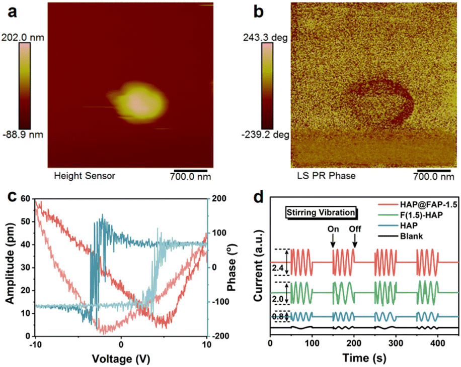 | ||
| Fig. 4 PFM images of HAP@FAP-1.5 (a) topography; (b) phase diagram; (c) amplitude butterfly line and phase hysteresis line; (d) piezoelectric discharge signals of HAP, HAP@FAP-1.5, and F(1.5)-HAP under magnetic stirring (1200 rpm). | ||
The reason why HAP@FAP-1.5 exhibited the highest piezoelectric response amplitude could be attributed to the strain gradient built in HAP@FAP-1.5, inducing a synergistic effect between the flexoelectricity and piezoelectricity. An electrochemical workstation was used to test the piezoelectric current signals output of HAP, HAP@FAP-1.5, and F(1.5)-HAP driven by mechanical stirring. As shown in Fig. 4d, when magnetic stirring was provided, significant piezoelectric discharge signals on these catalysts could be generated by harvesting the fluid flow mechanical energy, in which HAP@FAP-1.5 had the highest electrical signal output, while the electrical signal was negligible in the electrolyte solution without the catalyst.
2.3 Piezocatalytic activity and degradation pathway
The piezocatalytic activities of the catalysts were evaluated by using PHE-contaminated kaolin clay (2 g, 200 mg kg−1) as a model. The degradation curves of the three catalysts are shown in Fig. 5a. Since ultrasound could promote the mixing and fragmentation of soil, as well as the desorption and diffusion of PHE from soil, the adsorption process of PHE by the catalysts before degradation was studied. In terms of the adsorption capacity, a negligible adsorption of hydrophobic by PHE was observed due to its nanorod morphology and unmodified surface without sufficient adsorption sites. However, after the introduction of the hydrophobic F element, the contact opportunity between HAP@FAP-1.5 (or F(1.5)-HAP) and hydrophobic PHE increased, thereby improving the adsorption capacity of both for PHE. Notably, compared with F(1.5)-HAP, the FAP shell on the superficial layer of HAP@FAP-1.5 had more F sites, making it more hydrophobic, as proved by the contact angle test results in Fig. S8,† so its adsorption capacity for PHE was stronger than F(1.5)-HAP. For contrast, a series of blank tests without catalysts or ultrasonic were performed (Fig. 5a and S9a†), and it was found that PHE could only be adsorbed not degraded without ultrasonic treatment. During the degradation process, HAP@FAP-1.5 showed the best piezocatalytic activity, and its degradation efficiency of PHE reached 78.99% under ultrasonic vibration for 120 min. In Fig. 5b, HAP@FAP-1.5 exhibited the highest k value (0.01389 min−1), which was about 2.33 and 1.65 times that of HAP and F(1.5)-HAP, respectively. These results demonstrated that flexoelectricity induced by the strain gradient in HAP@FAP-1.5 core–shell structure was well coupled with the piezoelectricity of HAP, resulting in stronger piezocatalytic activity. | ||
| Fig. 5 Degradation efficiency of PHE in soil. (a) Reaction conditions: [PHE]0 = 200 mg kg−1, [catalyst]0 = 20 mg (1%), Vw/Ms = 20:2 (mL g−1), power = 600 W; (b) degradation rate constants (min−1); (c) degradation with different dosages of HAP@FAP-1.5; (d) degradation rate constants (min−1); (e) degradation with different water–soil ratio conditions (Vw/Ms, mL g−1) by HAP@FAP-1.5; (f) degradation rate constants (min−1). | ||
During the piezocatalytic process in soil suspension, there were several factors that had significant influences on the catalytic performance, including the dosage of catalysts, the water–soil ratio, and ultrasonic power. Therefore, taking HAP@FAP-1.5 as an example, the influence of these factors on the catalytic degradation performance was explored. It can be observed from Fig. 5c and d that the removal rate of PHE improved with the increase in the dosage of the catalysts (based on the quality of the soil). When the dosage of the catalyst was increased to 5% (100 mg) and 10% (200 mg), the removal rate of PHE could reach 90.51% and 100% within 120 min, and the k values were about 1.54 and 2.71 times that of the initial conditions, respectively. Furthermore, when the dosage reached 10% (200 mg), the PHE in soil was completely degraded.
These results showed that the increasing dosage of catalyst could effectively enhance the degradation efficiency of PHE in soil. Considering the low cost and good biocompatibility of HAP, HAP@FAP-1.5 showed potential prospect for large-scale soil remediation. Fig. 5e and f showed that the removal rate of PHE also increased with the increase in the water–soil ratio. When the water–soil ratio was 20:4, the penetration ability of ultrasound decreased due to the increase in the suspension density, resulting in weaker external mechanical stress applied to the catalysts, so that the final degradation efficiency greatly declined, which only reached 44.46% at 120 min, and its k value was about 0.32 times that of the initial conditions. When the water–soil ratio increased to 20:1, the external mechanical stress generated by ultrasound could act more effectively on the catalyst and soil particles with the smaller suspension density, which not only enhanced the piezocatalytic activity, but also promoted the dispersion of PHE in the reaction system, leading to a great increase in the degradation efficiency. In this case, PHE could be completely removed within 90 min, with a k value approximately 2.57 times that of the initial condition. The impact of external mechanical stimulus was also explored by changing the size of the ultrasonic power. It can be seen from Fig. S10a† that the removal rates of PHE for 150, 300, and 600 W ultrasonic power within 120 min were approximately 31.4%, 50.3%, and 79.0%, respectively, with the corresponding degradation kinetic rate constants shown in Fig. S10b.† The greater the ultrasonic power, the higher the degradation efficiency, implying that enhanced synergetic effect between the piezoelectricity and flexoelectricity in HAP@FAP-1.5 could be generated by a larger external mechanical stress triggered by the increased ultrasonic power.
In order to validate the phenanthrene degradation mechanism, the intermediate products of PHE were identified by GC-MS. The mass spectra and corresponding intermediates are shown in Fig. S11.† Based on the literature and test results, the possible degradation pathway of PHE is proposed in Fig. 6. For path I, ·OH attacked the phenanthrene aromatic ring at the 9- and 10-positions to form 9,10-phenanthrenediol, because the 9,10-double bond of PHE was the most electron-rich position.35,36 However, 9,10-phenanthrenediol was not detected in our samples due to the fact that it can be easily transformed to 9,10-phenanthraquinone (m/z = 207), which is the most common product of phenanthrene identified in other reports. As for path II, ·O2− attacked the 10-position of PHE to form the ionic intermediates, which were further dehydrated and dehydrogenated to form phenanthro[9,10-b]oxirene (m/z = 192).37 After these two possible stages, these intermediates mentioned above were further oxidized to form more complex products, such as (E)-2-(2-carboxyvinyl)benzoic acid (m/z = 192), 2-cyclohexane-1-ol (m/z = 98), and 1,2-cyclohexanedione (m/z = 113). In particular, due to the presence of silicon in kaolin, there may also be silane substitution products during the reaction, such as trimethylsilyl 4-((trimethylsilyl)oxy)benzoate (m/z = 239), and trimethylsilyl 2-(2-hydroxyethyl)benzoate (m/z = 207).38 At the end of the piezocatalytic reaction, unstable intermediates underwent ring-opening and bridge cleavage reactions under the continuous attack of free radicals to generate small molecular products, such as 2-oxopent-4-dienoate (m/z = 116) and hex-2-enoic acid (m/z = 99), which were finally converted into CO2 and H2O.39
 | ||
| Fig. 6 Possible degradation pathways of PHE by the piezocatalysis of HAP@FAP-1.5. | ||
2.4 Piezocatalytic mechanism of HAP@FAP
The position of the valence band (VB) and conduction band (CB) determines the redox ability of a semiconductor. The optical absorbances of HAP, HAP@FAP-1.5, and F(1.5)-HAP were investigated by UV-visible adsorption spectroscopy (Fig. 7a). Compared with the pristine HAP, the slight red-shifted adsorption of HAP@FAP-1.5 could be interpreted as evidence of band trailing effects related to the disorder induced by impurity insertion into the HAP lattice. In addition, according to the relationship between (F(R)hν)1/2 and the photon energy, the optical band gaps (Eg) of HAP, HAP@FAP-1.5, and F(1.5)-HAP were estimated to be 5.97, 5.90, and 5.97 eV (Fig. 7b). The VBs of the catalysts were investigated by XPS (Fig. 7c), which turned out to be the same value: −3.13 V. Combining Eg and VB, the CB positions of the catalysts were determined, showing that of HAP@FAP-1.5 (−2.77 eV) was more positive than that of HAP and F(1.5)-HAP (−2.84 eV). Hence, in terms of the band position of the catalysts, the redox capacity of HAP@FAP-1.5 decreased. Therefore, the improvement of HAP@FAP-1.5's catalytic activity could be attributed to the synergistic effect of piezoelectricity and flexoelectricity, which was caused by the strain gradient in the core–shell structure. | ||
| Fig. 7 (a) UV images of HAP, HAP@FAP-1.5, and F(1.5)-HAP; (b) band gap diagram; (c) XPS-VB of HAP, HAP@FAP-1.5, and F(1.5)-HAP; (d) energy band structure diagrams of HAP, HAP@FAP-1.5, and F(1.5)-HAP. | ||
The role of active free radicals was determined through free radical trapping experiments. IPA, BQ, and EDTA-2Na were used as scavengers for hydroxyl radicals (·OH), superoxide radicals (·O2−), and holes (h+), respectively, and the results are shown in Fig. 8a. After adding BQ, the degradation efficiency of PHE decreased to 41.90%, indicating ·O2− was the dominant active species in the piezocatalysis process. After ·OH was captured, the degradation efficiency was very similar to that with the addition of BQ (120 min, 30.99%), which meant that ·OH was generated by the conversion of ·O2− in the piezocatalysis process. However, after adding EDTA, the degradation efficiency was significantly improved compared with the blank, which may be attributed to the fact that the capture of h+ was helpful to the inhibition of carrier recombination.40 It was also further demonstrated that the main active species ·OH were derived from ·O2−. From Fig. 8b, it can be observed more intuitively that after the addition of IPA and BQ, the degradation rates of PHE were only 0.17 times and 0.28 times that of the blank, while the degradation rate after adding EDTA-2Na was up to 1.99 times that of the blank.
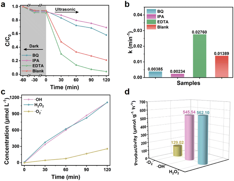 | ||
| Fig. 8 The effect of scavengers on piezocatalysis with HAP@FAP-1.5 for (a) the degradation of PHE; (b) corresponding degradation kinetic rate constants (min−1); (c) concentration change curves of ·O2−, ·OH, and H2O2; (d) corresponding productivities in 120 min under ultrasound. | ||
In order to further prove the existence of ·O2− and ·OH and determine the productivity, the NBT conversion method41 and the TA-PL method were used.42 As shown in Fig. S12a and b,† the fluorescence intensity of 2-hydroxyterephthalic acid (TA-OH) gradually increased at 426 nm, meanwhile, the absorbance of NBT at 259 nm gradually decreased as the ultrasound time was prolonged, indicating the continuous generation of ·OH and ·O2−. In addition, H2O2 is an important intermediate in the two-step reduction reaction between O2 and e−, so the concentration of H2O2 generated in the piezocatalytic process was detected by the iodine method. The gradual increase in the UV absorption peak at 349 nm (Fig. S12c†) indicated the stable generation of H2O2. It is worth noting that the concentration of H2O2 within 120 min was up to 1112.60 μmol L−1 (Fig. 8c and d), which was very close to the output of the main active species ·OH (1111.45 μmol L−1), and much higher than that of ·O2− (258.00 μmol L−1). These results further proved that part of the ·OH was generated by the two-step reduction reaction between O2 and e−.
Based on the above results and analysis, the possible mechanism of PHE degradation caused by piezoelectric polarization is proposed in Fig. 9. In this mechanism, a gradient core–shell structure is formed with the interdiffusion between OH− and F−. Contributing to the difference in crystal structure between HAP and FAP, electric polarization (i.e., flexoelectricity) is generated by the strain gradient, which can be coupled with the piezoelectric effect of HAP to enhance the piezocatalytic activity. Under the continuous external stress triggered by ultrasound, a piezoelectric potential can be generated by the deformed HAP@FAP-1.5. The free electrons and holes can be driven to the opposite surface by the built-in piezoelectric field, producing reactive species. Since the CB of HAP@FAP-1.5 (−2.74 V) is more negative than the reduction potential of O2/·O2− (−0.33 V vs. NHE), e− can react with O2 to form ·O2− (eqn (3)), which are finally converted into the dominant ·OH (eqn (5)). At the same time, ultrasound can also promote the desorption of PHE from soil and the dispersion of the catalyst in heterogeneous systems, thus improving the catalytic activity of HAP@FAP-1.5. The generated reactive oxygen species (ROS) undergo a series of redox reactions with the PHE adsorbed on the surface of the catalysts, which are finally degraded into small molecule products. The possible reactions are as follows:
| HAP@FAP-1.5 + Ultrasound → h+ + e− | (2) |
| O2 + e− → ·O2− | (3) |
| O2 + 2e− + 2H+ → H2O2 | (4) |
| H2O2 + e− + H+ → H2O + ·OH | (5) |
| ·OH + PHE → degraded products | (6) |
 | ||
| Fig. 9 Schematic illustration of the proposed mechanism for piezocatalytic degradation by HAP@FAP. | ||
3 Conclusions
In this work, HAP@FAP with a heterogeneous core–shell structure was fabricated by surface-gradient F-doping in hydroxyapatite for the enhanced piezocatalytic degradation of PHE in soil, which could degrade 79% PHE (200 mg kg−1 in soil) in 120 min. On the one hand, the high degradation efficiency could be attributed to the flexoelectricity induced by the chemical heterogeneities-induced lattice strain gradient, significantly improving the piezoelectric coefficient. On the other hand, ultrasound could effectively enhance the desorption of PHE from soil to the aqueous phase, where the oxidation process is most effective, thereby increasing the degradation efficiency. What's more, due to the good biocompatibility, low cost, and wide range of sources, HAP@FAP can well achieve the requirements of in situ soil remediation.4 Experimental section
4.1 Materials and reagents
All materials and reagents were used without purification. Anhydrous calcium chloride (CaCl2), ammonia (NH3·H2O), dichloromethane (DCM), kaolin clay (Al2O3·2SiO2·2H2O), and phenanthrene (PHE) were purchased from Macklin Biochemical Technology Co., Ltd, China. Anhydrous sodium dihydrogen phosphate (NaH2PO4) and sodium fluoride (NaF) were purchased from Aladdin Reagent (Shanghai) Co., Ltd.4.2 Preparation of HAP@FAP
Pure HAP nanorods were prepared using hydrothermal methods reported in our previous research work. First, 0.2 mmol HAP powder was added to NaF solution with different concentrations (2, 4, 6, and 8 mM) in the ratios of n(Ca):n(F) = 10:0.5, 10:1, 10:1.5, 10:2, followed by stirring for 0.5 h to obtain homogeneous mixtures. After that, the pH value of the mixed solution was adjusted to 12 by adding ammonia. The resulting suspension was transferred to a Teflon-lined autoclave and heated to 200 °C for 24 h. After cooling to room temperature, the sediment was collected and washed with deionized water and ethanol several times, followed by freeze-drying to obtain the HAP@FAP-x (x = 0.5, 1, 1.5, 2) core–shell structures. As a control, an F-doped HAP sample named as F(1.5)-HAP was prepared by adding NaF to the precursor solution with the ratio of n(Ca):n(F) = 10:1.5 during the preparation of HAP.
4.3 Characterization
The morphology and elemental mapping images were characterized by scanning electron microscopy (SEM, Regulus 8230 and EVO 18) operated at 15 kV electron accelerating voltage in high vacuum conditions. The lattice distributions of the as-prepared samples were further observed by high-resolution transmission electron microscopy (HRTEM, FEI Tecnai G2 F20) operated at 200 kV with LaB6 filament of 0.24 nm point resolution coupled with Gatan Microscopy Suite software. The crystal structures of the as-prepared materials were analyzed by X-ray powder diffraction (XRD, X'Pert-Pro MPD, Cu Kα, 40 kV and 40 mA) at a scan rate of 0.02° per second in the 2θ range from 5° to 80°. The elemental composition and valence band of the catalysts were measured by X-ray photoelectron spectroscopy (XPS, ESCALAB MK II) with an Al-Kα X-ray source. The absorption band edges were measured by ultraviolet-visible spectroscopy (UV-vis, Shimadzu UV-3600) in the wavelength range from 200 to 800 nm, using BaSO4 as the reflectance standard reference. The intensity of the hydroxyl signal was characterized using Fourier-transform infrared spectroscopy (FTIR, VERTEX 70) at a scan rate of 4 cm−1 per second in the scanning range from 600 to 4000 cm−1. The piezoresponse force microscopy (PFM) measurements were characterized with atomic force microscopy (AFM, Dimension Icon, Bruker) operated at a tip bias voltage of 6000 mV with a conductive Pt/Ir probe (SCM-PIT-V2, Bruker) and Au/Si conductive substrate. Gas chromatography-mass spectrometry (GC-MS, QP2020 NX) was used to detect the residual amount of PHE in soil and intermediate products produced during degradation.4.4 Electrochemical measurements
Piezoelectric discharge tests were carried out using a CHI 760E electrochemical workstation with a standard three-electrode configuration. Glassy carbon (0.197 cm2 surface area), Pt wire, and Ag/AgCl electrodes correspondingly served as the working, counter, and reference electrodes. Also, 50 mL PBS (0.1 M, pH 7.4) solution containing 2 mM ethylenediaminetetraacetic acid disodium salt served as the electrolyte. Different samples were dispersed into the electrolyte (2 mg mL−1) with periodic magnetic stirring (1200 rpm) for the piezoelectric discharge output measurements.4.5 Degradation experiments
Chemically pure kaolin was used as the simulated soil. PHE-contaminated soil was prepared by adding 10 mL 200 ppm PHE in DCM solution to 10 g kaolin clay, followed by thorough mixing for 24 h using a multi-tube vortex oscillator and air drying to completely evaporate the DCM. The soil samples were then ground using a 2 mm-mesh screening. The final PHE concentration was 200 mg kg−1.The piezocatalytic activity of HAP@FAP-x was evaluated by using PHE as the target pollutant in soil. An ultrasonic cleaner was used (KQ3200DB, 600 W and 45 kHz) to provide periodic local mechanical strain to the nanostructures. The proposed processing diagrams of phenanthrene removal in soil and the degradation experiments are shown in Fig. 10 and S1.† Here, 2 g contaminated soil and 20 mg catalysts were dispersed uniformly in 20 mL deionized water by an oscillator. Prior to degradation, the mixture was stirred for 1 h in the dark to obtain adsorption/desorption equilibrium. Afterwards, the resultant solution was put into the above ultrasonic source and then subjected to a certain stress. Next, a 1 mL suspension was sampled out at regular intervals, followed by freeze-drying to obtain dry soil samples. Then DCM was added into the samples for the extraction of the residual PHE assisted by ultrasound for 2 h. Then, the suspension was centrifuged, and the supernatant was filtered by a 0.22 μm membrane. The concentration of residual PHE was determined by GC-MS with DCM used as the mobile phase. The specific parameters of the GC-MS tests are detailed in the National Environmental Protection Standard of China HJ 805-2016 and are listed in Table S1.† Fig. S2† shows the standard curve (R2 = 0.999) and extraction efficiency of PHE from the soil. All the average recovery rates at different concentrations of PHE exceeded 95%.
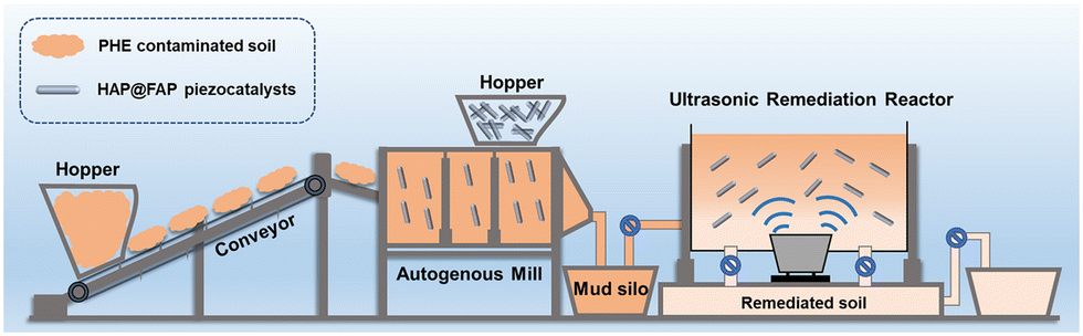 | ||
| Fig. 10 Diagram for the proposed processing of phenanthrene removal in soil under ultrasonic treatment. | ||
Conflicts of interest
There are no conflicts to declare.Acknowledgements
We gratefully acknowledge the financial support provided by the National Natural Science Foundation of China (51973148 and 21938006), the National Key Technology R&D Program (2020YFC1818401), Basic Research Project of Leading Technology in Jiangsu Province (BK20202012) and project supported by the Priority Academic Program Development of Jiangsu Higher Education Institutions (PAPD).References
- J. W. Choi, M. Kim, G. Song, Y. Kho, K. Choi, M. Y. Shin and S. Kim, Toxicokinetic analyses of naphthalene, fluorene, phenanthrene, and pyrene in humans after single oral administration, Sci. Total Environ., 2023, 870, 161899 CrossRef CAS PubMed.
- Z. Zhang, H. Guo, J. Sun, X. Gong, C. Wang and H. Wang, Anaerobic phenanthrene biodegradation by a newly isolated sulfate-reducer, strain PheS1, and exploration of the biotransformation pathway, Sci. Total Environ., 2021, 797, 149148 CrossRef CAS.
- B. Qu, P. Li, L. Bai, Y. Qu, Z. Li, Z. Zhang, B. Zheng, J. Sun and L. Jing, Atomically dispersed Zn-N5 sites immobilized on g-C3N4 nanosheets for ultrasensitive selective detection of phenanthrene by dual ratiometric fluorescence, Adv. Mater., 2023, 35, 2211575 CrossRef CAS.
- L. Chu, L. Cang, Z. Sun, X. Wang, G. Fang and J. Gao, Reagent-free electrokinetic remediation coupled with anode oxidation for the treatment of phenanthrene polluted soil, J. Hazard. Mater., 2022, 433, 128724 CrossRef CAS.
- C. Dai, Y. Han, Y. Duan, X. Lai, R. Fu, S. Liu, K. H. Leong, Y. Tu and L. Zhou, Review on the contamination and remediation of polycyclic aromatic hydrocarbons (PAHs) in coastal soil and sediments, Environ. Res., 2022, 205, 112423 CrossRef CAS PubMed.
- D. Wen, X. Guo, Q. Li and R. Fu, Enhanced electrokinetically-delivered persulfate and alternating electric field induced thermal effect activated persulfate in situ for remediation of phenanthrene contaminated clay, J. Hazard. Mater., 2022, 423, 127199 CrossRef CAS PubMed.
- X. Chen, B. Yang, P. Oleszczuk, Y. Gao, X. Yuan, W. Ling and M. G. Waigi, Vanadium oxide activates persulfate for degradation of polycyclic aromatic hydrocarbons in aqueous system, Chem. Eng. J., 2019, 364, 79–88 CrossRef CAS.
- S. Yu, X. Gu, S. Lu, Y. Xue, X. Zhang, M. Xu, Z. Qiu and Q. Sui, Degradation of phenanthrene in aqueous solution by a persulfate/percarbonate system activated with CA chelated-Fe(II), Chem. Eng. J., 2018, 333, 122–131 CrossRef CAS.
- A. Checa-Fernández, A. Santos, L. O. Conte, A. Romero and C. M. Domínguez, Enhanced remediation of a real HCH-polluted soil by the synergetic alkaline and ultrasonic activation of persulfate, Chem. Eng. J., 2022, 440, 135901 CrossRef.
- Y.-T. Li, J.-J. Zhang, Y.-H. Li, J.-L. Chen and W.-Y. Du, Treatment of soil contaminated with petroleum hydrocarbons using activated persulfate oxidation, ultrasound, and heat: A kinetic and thermodynamic study, Chem. Eng. J., 2022, 428, 131336 CrossRef CAS.
- Y. J. Lei, J. Zhang, Y. Tian, J. Yao, Q. S. Duan and W. Zuo, Enhanced degradation of total petroleum hydrocarbons in real soil by dual-frequency ultrasound-activated persulfate, Sci. Total Environ., 2020, 748, 141414 CrossRef CAS.
- Y.-J. Lei, Y. Tian, Z. Sobhani, R. Naidu and C. Fang, Synergistic degradation of PFAS in water and soil by dual-frequency ultrasonic activated persulfate, Chem. Eng. J., 2020, 388, 124215 CrossRef CAS.
- S. Tu, Y. Guo, Y. Zhang, C. Hu, T. Zhang, T. Ma and H. Huang, Piezocatalysis and piezo-photocatalysis: Catalysts classification and modification strategy, reaction mechanism, and practical application, Adv. Funct. Mater., 2020, 30, 2005158 CrossRef CAS.
- F. Gao, M. Fang, S. Zhang, M. Ni, Y. Cai, Y. Zhang, X. Tan, M. Kong, W. Xu and X. Wang, Symmetry-breaking induced piezocatalysis of Bi2S3 nanorods and boosted by alternating magnetic field, Appl. Catal., B, 2022, 316, 121664 CrossRef CAS.
- Y. Huang, B. Lv, C. Zhao, J. Yin, Y. Wang, Y. Wang, X. Fu, T. Wu, J. Wu and X. Zhang, High-efficiency reactive oxygen species generation by multiphase and TiO6 distortion-mediated superior piezocatalysis in perovskite ferroelectrics, Adv. Funct. Mater., 2023, 33, 2210726 CrossRef CAS.
- W. Tian, J. Qiu, N. Li, D. Chen, Q. Xu, H. Li, J. He and J. Lu, Efficient piezocatalytic removal of BPA and Cr(VI) with SnS2/CNFs membrane by harvesting vibration energy, Nano Energy, 2021, 86, 106036 CrossRef CAS.
- Y. Wei, Y. Zhang, W. Geng, H. Su and M. Long, Efficient bifunctional piezocatalysis of Au/BiVO4 for simultaneous removal of 4-chlorophenol and Cr(VI) in water, Appl. Catal., B, 2019, 259, 118084 CrossRef CAS.
- M. Ibrahim, M. Labaki, J. M. Giraudon and J. F. Lamonier, Hydroxyapatite, a multifunctional material for air, water and soil pollution control: A review, J. Hazard. Mater., 2020, 383, 121139 CrossRef CAS.
- S. Li, Y. Li, W. Shen, Y. Bai and L. Kong, Hydroxyapatite-based catalysis in environmental decontamination, J. Cleaner Prod., 2022, 380, 134961 CrossRef CAS.
- Y. Miao, W. Tian, J. Han, N. Li, D. Chen, Q. Xu and J. Lu, Oxygen vacancy-induced hydroxyl dipole reorientation in hydroxyapatite for enhanced piezocatalytic activity, Nano Energy, 2022, 100, 107473 CrossRef CAS.
- Y. Zhou, H. Wang, X. Liu, S. Qiao, D. Shao, J. Zhou, L. Zhang and W. Wang, Direct piezocatalytic conversion of methane into alcohols over hydroxyapatite, Nano Energy, 2021, 79, 105449 CrossRef CAS.
- Y.-g. Kim, H. Kim, G.-J. Lee, H.-U. Lee, S. G. Lee, C. Baek, M.-K. Lee, J.-J. Park, Q. Wang, S. B. Cho, C. K. Jeong and K.-I. Park, Flexoelectric-boosted piezoelectricity of BaTiO3@SrTiO3 core-shell nanostructure determined by multiscale simulations for flexible energy harvesters, Nano Energy, 2021, 89, 106469 CrossRef CAS.
- F. Vasquez-Sancho, A. Abdollahi, D. Damjanovic and G. Catalan, Flexoelectricity in bones, Adv. Mater., 2018, 30, 1705316 CrossRef.
- Y. Wang, A. Vogel, M. Sachs, R. S. Sprick, L. Wilbraham, S. J. A. Moniz, R. Godin, M. A. Zwijnenburg, J. R. Durrant, A. I. Cooper and J. Tang, Current understanding and challenges of solar-driven hydrogen generation using polymeric photocatalysts, Nat. Energy, 2019, 4, 746–760 CrossRef CAS.
- Q. Chang, W. Xu, N. Li, C. Xue, Y. Wang, Y. Li, H. Wang, J. Yang and S. Hu, Dynamic restructuring of carbon dots/copper oxide supported on mesoporous hydroxyapatite brings exceptional catalytic activity in the reduction of 4-nitrophenol, Appl. Catal., B, 2020, 263, 118299 CrossRef CAS.
- X. Ge, J. Zhao, K. D. Esmeryan, X. Lu, Z. Li, K. Wang, F. Ren, Q. Wang, M. Wang and B. Qian, Cicada-inspired fluoridated hydroxyapatite nanostructured surfaces synthesized by electrochemical additive manufacturing, Mater. Des., 2020, 193, 108790 CrossRef CAS.
- X. Ge, J. Zhao, X. Lu, Z. Li, K. Wang, F. Ren, M. Wang, Q. Wang and B. Qian, Controllable phase transformation of fluoridated calcium phosphate ultrathin coatings for biomedical applications, J. Alloys Compd., 2020, 847, 155920 CrossRef CAS.
- K. Tõnsuaadu, K. A. Gross, L. Plūduma and M. Veiderma, A review on the thermal stability of calcium apatites, J. Therm. Anal. Calorim., 2011, 110, 647–659 CrossRef.
- E. O. López, A. L. Rossi, B. S. Archanjo, R. O. Ospina, A. Mello and A. M. Rossi, Crystalline nano-coatings of fluorine-substituted hydroxyapatite produced by magnetron sputtering with high plasma confinement, Surf. Coat. Technol., 2015, 264, 163–174 CrossRef.
- Z. Boukha, J. R. González-Velasco and M. A. Gutiérrez-Ortiz, Exceptional performance of gold supported on fluoridated hydroxyapatite catalysts in CO-cleanup of H2-rich stream: High activity and resistance under PEMFC operation conditions, Appl. Catal., B, 2021, 292, 120142 CrossRef CAS.
- J. Li, J. Camardese, R. Shunmugasundaram, S. Glazier, Z. Lu and J. R. Dahn, Synthesis and characterization of the lithium-rich core-shell cathodes with low irreversible capacity and mitigated voltage fade, Chem. Mater., 2015, 27, 3366–3377 CrossRef CAS.
- H. Huang, B. Dai, W. Wang, C. Lu, J. Kou, Y. Ni, L. Wang and Z. Xu, Oriented built-in electric field introduced by surface gradient diffusion doping for enhanced photocatalytic H2 evolution in CdS nanorods, Nano Lett., 2017, 17, 3803–3808 CrossRef CAS PubMed.
- J. C. Rendón-Angeles, K. Yanagisawa, N. Ishizawa and S. Oishi, Topotaxial conversion of chlorapatite and hydroxyapatite to fluorapatite by hydrothermal ion exchange, Chem. Mater., 2000, 12, 2143–2150 CrossRef.
- B. Fu, J. Li, H. Jiang, X. He, Y. Ma, J. Wang and C. Hu, Modulation of electric dipoles inside electrospun BaTiO3@TiO2 core-shell nanofibers for enhanced piezo-photocatalytic degradation of organic pollutants, Nano Energy, 2022, 93, 106841 CrossRef CAS.
- H. Li, Y. Yao, J. Zhang, J. Du, S. Xu, C. Wang, D. Zhang, J. Tang, H. Zhao and J. Zhou, Degradation of phenanthrene by peroxymonosulfate activated with bimetallic metal-organic frameworks: Kinetics, mechanisms, and degradation products, Chem. Eng. J., 2020, 397, 125401 CrossRef CAS.
- H. Lee, H. Anwer and J.-W. Park, Graphene quantum dots on stainless-steel nanotubes for enhanced photocatalytic degradation of phenanthrene under visible light, Chemosphere, 2020, 246, 125761 CrossRef CAS PubMed.
- L. Wen, Y. Huang, W. Wang, L. Zhang, J. Xu, Z. Li, P. Xu and H. Tang, A novel Diaphorobacter sp. strain isolated from saponification wastewater shows highly efficient phenanthrene degradation, Environ. Res., 2022, 214, 114047 CrossRef CAS PubMed.
- Y. Wang, M. Nie, Z. Diwu, F. Chang, H. Nie, B. Zhang, X. Bai and Q. Yin, Toxicity evaluation of the metabolites derived from the degradation of phenanthrene by one of a soil ubiquitous PAHs-degrading strain Rhodococcus qingshengii FF, J. Hazard. Mater., 2021, 415, 125657 CrossRef CAS PubMed.
- N. Kashyap, K. Roy and V. S. Moholkar, Mechanistic investigations in ultrasound-assisted biodegradation of phenanthrene, Ultrason. Sonochem., 2020, 62, 104890 CrossRef CAS.
- T. Ren, W. Tian, Q. Shen, Z. Yuan, D. Chen, N. Li and J. Lu, Enhanced piezocatalysis of polymorphic few-layered MoS2 nanosheets by phase engineering, Nano Energy, 2021, 90, 106527 CrossRef CAS.
- R. Frankowski, J. Płatkiewicz, E. Stanisz, T. Grześkowiak and A. Zgoła-Grześkowiak, Biodegradation and photo-Fenton degradation of bisphenol A, bisphenol S and fluconazole in water, Environ. Pollut., 2021, 289, 117947 CrossRef CAS.
- J. Long, T. Ren, J. Han, N. Li, D. Chen, Q. Xu, H. Li and J. Lu, Heterostructured BiFeO3@CdS nanofibers with enhanced piezoelectric response for efficient piezocatalytic degradation of organic pollutants, Sep. Purif. Technol., 2022, 290, 120861 CrossRef CAS.
Footnote |
| † Electronic supplementary information (ESI) available. See DOI: https://doi.org/10.1039/d3im00093a |
| This journal is © Institute of Process Engineering of CAS 2024 |