
 Open Access Article
 This Open Access Article is licensed under a
 Creative Commons Attribution 3.0 Unported Licence
Inducing porosity in xylose-derived FeNC electrocatalysts for alkaline oxygen reduction†
Lorenzo
Mazzoli
a,
Angus
Pedersen
 *ab,
Simon
Kellner
a,
Robert D.
Hunter
a,
Rongsheng
Cai
c,
Mengnan
Wang
ab,
Kevin
Sivula
d,
Sarah J.
Haigh
c and
Jesús
Barrio
*a
*ab,
Simon
Kellner
a,
Robert D.
Hunter
a,
Rongsheng
Cai
c,
Mengnan
Wang
ab,
Kevin
Sivula
d,
Sarah J.
Haigh
c and
Jesús
Barrio
*a
aDepartment of Chemical Engineering, Imperial College London, London SW7 2AZ, UK. E-mail: a.pedersen19@imperial.ac.uk; j.barrio-hermida@imperial.ac.uk
bDepartment of Materials, Royal School of Mines, Imperial College London, London SW7 2AZ, UK
cDepartment of Materials, University of Manchester, Oxford Road, Manchester, M13 9PL, UK
dLaboratory for Molecular Engineering of Optoelectronic Nanomaterials, Institute of Chemical Sciences and Engineering, École Polytechnique Fédérale de Lausanne, 1015 Lausanne, Switzerland
First published on 2nd February 2024
Abstract
Iron–nitrogen–carbon (FeNC) electrocatalysts are emerging as a low-cost alternative to Pt-based materials for electrochemical oxygen reduction at the cathode of alkaline exchange membrane hydrogen fuel cells. The valorisation of waste biomass is a sustainable pathway that could allow the large-scale production of such catalysts. By means of hydrothermal carbonization (HTC), a biomass-derived carbohydrate can be converted into a carbonaceous framework, however, the electrocatalytic performance of the metal–nitrogen–carbon electrocatalysts prepared through HTC is suboptimal owing to the lack of microporosity in the highly crosslinked carbon frameworks. In this work, we address this issue by adding polystyrene sulfonate (kayexalate) in the HTC of xylose. Kayexalate's negative charges mitigate particle aggregation, resulting in smaller carbon-based particles, with the O2 activation leading to a four-fold increase in specific surface area (127 vs. 478 m2 g−1). Subsequent high-temperature pyrolysis in the presence of an N and Fe source leads to an active FeNC. This produces a corresponding increase in the electrocatalytic activity for the oxygen reduction in alkaline media in a rotating disk electrode (1.45 vs. 14.3 A g−1 at 0.8 V vs. RHE) and in a gas diffusion electrode at high current densities (≥2 A cm−2). The sustainable character of the reported catalyst as well as the high electrocatalytic activity at industrially relevant current densities provides a pathway to catalyst design for low-cost cathodes in alkaline exchange membrane fuel cells.
Introduction
The oxygen reduction reaction (ORR) is a crucial electrochemical process in energy conversion devices such as metal–air batteries, anion exchange membrane fuel cells (AEMFC) or proton exchange membrane fuel cells (PEMFC). In AEMFC it entails the four, or two-electron transfer to O2 molecules to form OH− or H2O2, respectively, in the surface of an efficient electrocatalyst, needed due to the sluggish kinetics of the reaction.1,2 While the two-electron ORR to form hydrogen peroxide as a valuable method to provide on-site a highly coveted chemical,3 a direct four-electron transfer is desired for high power density fuel cell applications. To date, Pt-based materials and their alloys are the most active and durable electrocatalysts for the four electron ORR.4 Nevertheless, the high cost of Pt has hindered the widespread adoption and advancement of fuel cell technology. Therefore, finding methods to reduce the Pt content on the cathode without compromising their activity, as well as the development of Pt-free electrocatalysts based on non-noble metals that match the performance of Pt-based catalysts can lead to the manufacture of sustainable fuel cells with reduced environmental impact and cost.5 AEMFC in particular could employ non-Pt-based catalysts, owing to the lower thermodynamic requirements of the alkaline ORR,6 as well as more affordable metallic components versus PEMFC, owing to the high pH conditions.7,8 Fe single atoms within nitrogen-doped carbon (FeNC) have emerged as the most active alternative to Pt-based catalysts.9,10 In these catalysts, an iron atom is coordinated to nitrogen atoms (Fe–Nx, where x = 2–511,12) that provide lone electron pairs and stabilize iron single sites. The carbon framework provides a supporting structure for the FeNx active sites, as well as electronic conductivity, stability, hierarchical porosity and electron-withdrawing or donating properties.13,14 In general, the synthetic approaches commonly employed to prepare FeNC catalysts entail the high-temperature pyrolysis of carbon, nitrogen, and Fe-based precursors followed by harsh acidic treatments,15 and in most cases, the precursors require complex synthetic steps.16To align with the growing emphasis on combining sustainability and commercial viability, it becomes imperative to explore synthetic approaches that utilize sustainable sources for the preparation of efficient FeNC oxygen reduction electrocatalysts.17 In that regard, lignocellulosic biomass is considered a potential sustainable carbon precursor in the synthesis of electrocatalyst materials owing to its abundance as well as the high carbon and (often) heteroatom content.18,19 Furthermore, every year a significant portion of biomass waste (agricultural biomass production within the European Union amounts to approximately 956 Mt annually, with residues accounting for 46%)20 is left in fields to decompose or is eventually discarded and used as a low-grade energy source, contributing to greenhouse gas emissions. This abundant bio-waste can be converted into carbonaceous catalysts and supports by means of hydrothermal carbonization (HTC), which entails mild carbonization at temperatures <250 °C and self-generated pressure in the presence of water.21,22 Among the different types of biomass, hemicellulose can be used to obtain xylose. Commercially, hydrolysis of xylan (25–30% of corn cob, for instance) can be employed to produce xylose (C5H10O5).23,24 Xylose is therefore a cheap, abundant and sustainable carbon-based precursor which has been employed for the preparation of heterogeneous catalysts as well as FeNC materials.25 However, the electrochemical performance of xylose-derived FeNC oxygen reduction electrocatalysts is often low. This is due to the low porosity and specific surface area of the materials obtained after hydrothermal carbonization, which does not allow full access to the FeNx active sites. For instance, Feng et al.26 developed a Fe–N–C xylose-derived electrocatalyst, using melamine and Iron(II) chloride as nitrogen and iron precursors. However, the obtained electrocatalysts displayed specific surface areas ranging 40–70 m2 g−1, which led to moderate oxygen reduction activity in alkaline media. The introduction of microporosity is crucial for the development of active FeNC electrocatalysts, as it allows the formation of a higher number of active sites.27,28 Templating methods with either silica or molten salts (ionothermal carbonization29) can lead to high surface areas. Our group for instance employed magnesium chloride hexahydrate in the presence of 2,4,6-triaminopyrimidine as reactants for the synthesis of highly porous nitrogen-doped carbons that efficiently exposed the FeNx active sites, resulting in a much higher surface area of 3295 m2 g−1.30 Sodium salts have been widely employed as porogens as well.31–33 Waterhouse and co-workers for instance employed a mixture of zeolitic-imidazole framework 8 and NaCl to synthesize FeN4 electrocatalysts with a surface area >1900 m2 g−1 and 26.3 × 10¹⁹ sites g−1.34 Silica templating has been thoroughly investigated by Atanassov and co-workers, who often observe electrocatalysts with specific surface areas up to 600 m2 g−1.14,35 Yet such templating methods require a high salt/organic precursor ratio as well as an acid wash, which requires HF in the case of SiO2, which leads to potential significant impacts on human health.6 Mazzucato and coworkers, on the other hand, employed CO2 and steam activation to regulate the formation of micro and mesopores in carbon black, which increased the site density and turnover frequency of the final catalyst.36
Therefore, in this work, we have addressed this issue by inducing microporosity in xylose-based FeNC electrocatalyst through the addition of small amounts of poly(sodium 4-styrene sulfonate) (kayexalate) during the HTC of xylose. The charged sulfonate groups of kayexalate avoid the aggregation of the carbon particles during the HTC leading to a much smaller sphere size and increased surface area of the final material.26,37 The particle size reduction in the hydrothermal spheres was proven through scanning electron microscopy (SEM) images. The enhancement in surface areas of the final catalysts (prepared by pyrolysis of the hydrothermal spheres in the presence of melamine and FeCl2) was evaluated with N2 sorption and double-layer capacitance (Cdl) measurements (proportional to the electrochemical surface area (ECSA)). The homogeneous distribution of nitrogen and iron was confirmed by means of scanning transmission electron microscopy – energy dispersive X-ray spectroscopy (STEM-EDX) – and the chemical composition was further evaluated by X-ray photoelectron spectroscopy (XPS). The electrochemical oxygen reduction activity was evaluated in alkaline electrolyte (0.1 M KOH) in a rotating disk electrode (RDE), where the insertion of kayexalate led to an almost 10-fold enhancement in the mass activity. Furthermore, owing to the increased specific surface area (478 m2 g−1) and microporosity, the material was tested in a gas diffusion electrode (GDE) configuration and compared to the state-of-the-art FeNC catalyst (PMF-D14401, Pajarito Powder).
Experimental
Materials synthesis
![[thin space (1/6-em)]](https://www.rsc.org/images/entities/char_2009.gif) 000000 g mol−1 powder) were added to the xylose solution and the same synthetic protocol was followed, the material was labelled HTC-XK.
000000 g mol−1 powder) were added to the xylose solution and the same synthetic protocol was followed, the material was labelled HTC-XK.
Electrochemical measurements
The electrochemical tests were carried out in a potentiostat Multi AUTOLAB m101 in O2 (99.99998% BIP® Plus) and N2 (99.9998% Ultrapure Plus) using as electrolyte 0.1 M KOH (99.995% suprapur). The electrolyte was poured into an electrochemical cell with three electrodes: an Ag/AgClsat (3M KCl) reference electrode, a glassy carbon rod as the counter electrode, and a glassy carbon RRDE as the working electrode. An ink, using 4 mg of material, 480 μg of isopropanol (99.5% Honeywell™, Fisher Scientific), 480 μg of 18.2 MΩ deionized water, and 40 μg of 5 wt% Nafion® D-521 (5% w/w in water and 1-propanol, Alfa Aesar) was prepared by bath ultrasonication (132 kHz ultrasonic cleaner, VWR) for 30 minutes until the catalyst was well dispersed and 12.64 μL were drop-casted onto the previously polished carbon part of the working electrode. The catalyst loading was therefore 0.26 mgCatalyst cm−2. The ink was dried under rotation (300 rpm) and heating. The Ag/AgCl electrode was calibrated in 0.1 M KOH with purging H2 (1 bar) using a 3 mm Pt RDE tip (Metrohm) as a working electrode. In the calibration process, the working electrode was rotated at 1600 rpm. A series of five cyclic voltammograms were recorded, spanning from −0.26 to −0.28 VAg/AgCl at a scan rate of 10 mV s−1.38 Before performing electrochemical tests, the electrolyte was purged with either N2 or O2 for 15 min. 10 cyclic voltammetry were recorded at 50 mV s−1 and 0 rpm in the potential range of 1.00 VRHE to 0.05 VRHE, to precondition the catalyst and evaluate the capacitive current. The catalyst performance was evaluated by recording cyclic voltammograms in O2 at 1600 rpm at 10 mV s−1 in the potential range 1.0 to 0.2 VRHE. The pseudocapacitance was then corrected by subtracting the current obtained from cyclic voltammetry in saturated N2 recorded at 1600 rpm. The ohmic drop was calculated for each measurement by means of electrochemical impedance measurements from 10−5–10−1 Hz (at open circuit potential) and by taking the first intercept of the real impedance axis in the Nyquist plot (without equivalent circuit fitting). Each potential value was then corrected with the electrolyte resistance and the measured current.The kinetic current densities (jkin) were calculated at 0.80 and/or 0.75 VRHE, using the geometric disk current density (jd) and the limiting current density (jlim) found at 0.3 VRHE following eqn. (1):
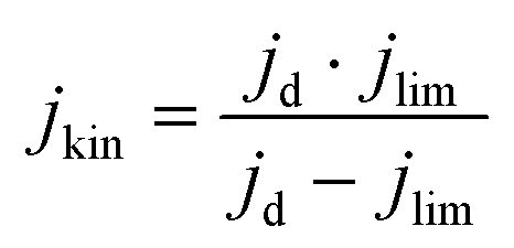 | (1) |
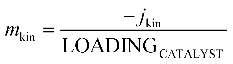 | (2) |
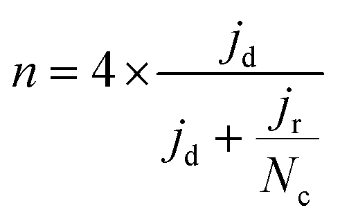 | (3) |
The selectivity was evaluated through the %H2O2 produced employing eqn (4):
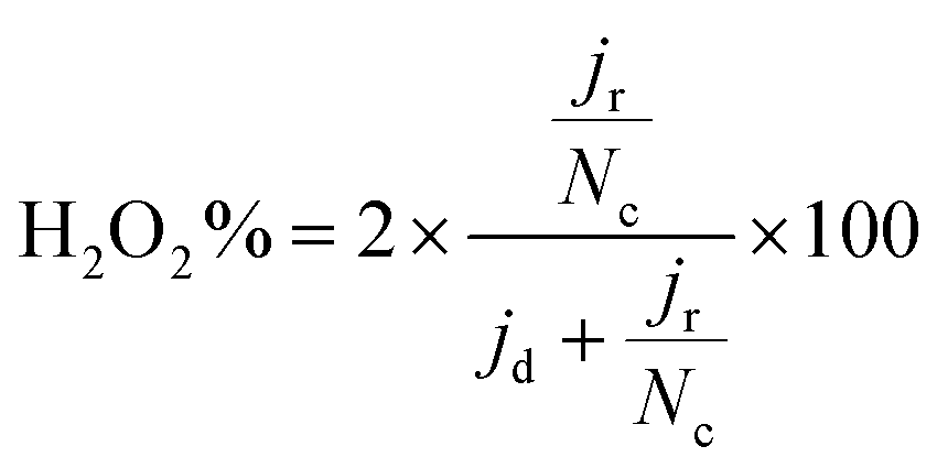 | (4) |
Subsequently, the double-layer capacitance Cdl was calculated by plotting the difference between the anodic and cathodic current density at a certain potential (in a non-faradaic region, at 0.50 VRHE) versus different scan rates (in this work 20, 40, 60 and 80 mV s−1).40 The tests were pursued in N2-saturated KOH 0.1 M, at 0 rpm. The slope of this linear plot is Cdl in F cm−2; by dividing this number by the total amount of loaded catalyst, a normalized value of Cdl in F g−1 is obtained. The double-layer capacitance provides valuable insights into the interfacial electrochemical behaviour and the extent to which an electrocatalyst participates in ORR reactions. By being directly proportional to the ECSA (electrochemical surface area), a higher Cdl indicates a larger electrochemically active surface area, often correlated with enhanced catalytic performance.41 The stability of the catalysts was evaluated through accelerated stress tests through cyclic voltammetry cycles at potentials between 0.8 and 0.4 VRHE in O2, at 100 mV s−1. The catalysts were then tested after 1000 and 8000 cycles by recording a cyclic voltammetry in the potential range 1.00–0.20 VRHE.
FeXK Gas Diffusion Electrodes (GDEs) were crafted in-house using an airbrush set and an Iwata Smart Jet Pro Airbrush compressor. The Pajarito PMFD14401 GDEs were created with an Exactacoat ultrasonic spray coater on a 5 cm2 gas diffusion layer (Freudenberg H23C8). The catalyst loading was 1.29mgFeNC cm−2, determined by pre- and post-weighing the gas diffusion layer after spraying. Electrochemical measurements were performed using a GDE setup filled with a 1 M KOH aqueous solution. The potentiostat PGSTAT204 with FRA32M Module (Metrohm) was employed, along with galvanostatic steps coupled with Electrochemical Impedance Spectroscopy (EIS). The detailed methodology, including ink formulation and spray-coating specifics, is provided in the ESI.† Procedures for all the material characterizations are also included in the ESI.†
Results and discussion
Xylose-based, hydrothermal carbon spheres were obtained by the HTC treatment of xylose at 220 °C in the presence and absence of kayexalate (Scheme 1). Gong et al.37 hypothesized that when incorporating kayexalate during the HTC of sugars, the polymer binds to the produced hydrochar and owing to its negative charge ensures that all the formed particles repel each other preventing them from cross-linking. SEM confirms the drastic decrease in the average diameter of the hydrothermal spheres produced with and without kayexalate (Fig. S1†). The particle sizes obtained with the usage of kayexalate are on average more than 10 times smaller (78 nm) compared to when only xylose is used (865 nm, Fig. 1 and Fig. S1†). Fourier Transformed Infrared Spectroscopy (FT-IR) was carried out to elucidate whether the addition of kayexalate modifies the chemical composition of the hydrothermal carbons (Fig. S2†). Very similar bands can be observed for both materials, namely C![[double bond, length as m-dash]](https://www.rsc.org/images/entities/char_e001.gif) O stretching vibration at 1698 cm−1, CC stretching vibration at 1610 cm−1, C–H stretching vibration at 1389 cm−1 and C–O stretching vibrations arising from furanic ethers (1216 cm−1) and primary alcohols (1020 cm−1). Bending vibrations corresponding to CC and C–H bonds can also be observed at lower wavelengths and, interestingly, no stretching vibrations arising from a sulfonate bond are observed in HTC-XK probably due to the low amount of kayexalate employed in the hydrothermal carbonization. Consequently, FT-IR characterization suggests minimal changes in chemical composition between both hydrochars. HTC-X and air-activated HTC-XK were then employed as carbon precursors for the synthesis of FeNC materials by pyrolysis at 900 °C in the presence of melamine and FeCl2. Nitrogen sorption measurements (Fig. 2a) show minor hysteresis and confirm the significant improvement in pore volume between the materials. FeXK exhibits a Brunauer–Emmett–Teller (BET) specific surface area of 478 m2 g−1, which is nearly four times greater than that of FeX (127 m2 g−1). Besides the specific surface area, the pore size distribution (Fig. 2b) demonstrates the increased micropore volume centered around 0.5 nm in FeXK versus FeX (0.179 and 0.045 cm3 g−1, respectively, Table S1†). These micropores contribute to high ORR performance since it has been postulated that micropores host active sites.27,28 We attribute this stark difference in microporosity to the presence of kayexalate and O2 activation, which create micropores on the sphere surface.25,37 Additionally, the mesopore size distribution in FeXK (Fig. 2b) shows an increased mesopore volume for pore widths >10 nm. Specifically, the mesopore pore volume in FeXK increases to 0.138 cm3 g−1, from 0.037 cm3 g−1 in FeX (Table S1†). The relative mesopore volume increase in FeXK is similar to its micropore increase, meaning the percentage of micropore volume in FeX (55%) remains unaffected following the incorporation of kayexalate in FeXK (57%).
O stretching vibration at 1698 cm−1, CC stretching vibration at 1610 cm−1, C–H stretching vibration at 1389 cm−1 and C–O stretching vibrations arising from furanic ethers (1216 cm−1) and primary alcohols (1020 cm−1). Bending vibrations corresponding to CC and C–H bonds can also be observed at lower wavelengths and, interestingly, no stretching vibrations arising from a sulfonate bond are observed in HTC-XK probably due to the low amount of kayexalate employed in the hydrothermal carbonization. Consequently, FT-IR characterization suggests minimal changes in chemical composition between both hydrochars. HTC-X and air-activated HTC-XK were then employed as carbon precursors for the synthesis of FeNC materials by pyrolysis at 900 °C in the presence of melamine and FeCl2. Nitrogen sorption measurements (Fig. 2a) show minor hysteresis and confirm the significant improvement in pore volume between the materials. FeXK exhibits a Brunauer–Emmett–Teller (BET) specific surface area of 478 m2 g−1, which is nearly four times greater than that of FeX (127 m2 g−1). Besides the specific surface area, the pore size distribution (Fig. 2b) demonstrates the increased micropore volume centered around 0.5 nm in FeXK versus FeX (0.179 and 0.045 cm3 g−1, respectively, Table S1†). These micropores contribute to high ORR performance since it has been postulated that micropores host active sites.27,28 We attribute this stark difference in microporosity to the presence of kayexalate and O2 activation, which create micropores on the sphere surface.25,37 Additionally, the mesopore size distribution in FeXK (Fig. 2b) shows an increased mesopore volume for pore widths >10 nm. Specifically, the mesopore pore volume in FeXK increases to 0.138 cm3 g−1, from 0.037 cm3 g−1 in FeX (Table S1†). The relative mesopore volume increase in FeXK is similar to its micropore increase, meaning the percentage of micropore volume in FeX (55%) remains unaffected following the incorporation of kayexalate in FeXK (57%).
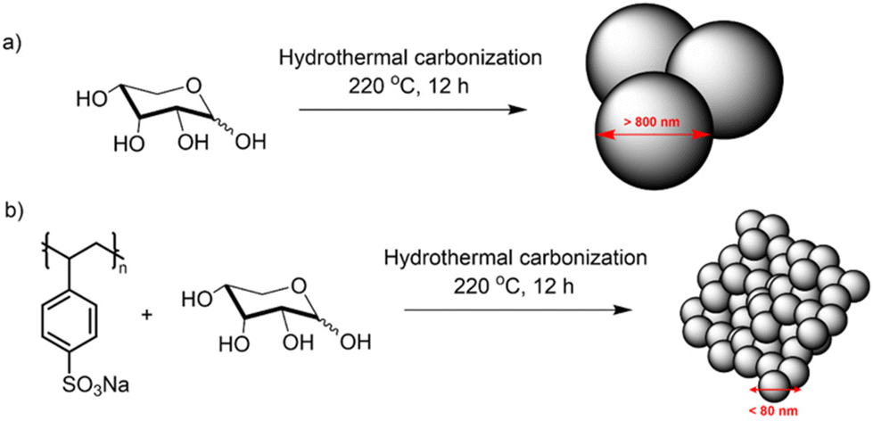 | ||
| Scheme 1 Hydrothermal synthesis of carbon spheres from Xylose without (a) and with (b) kayexalate. | ||
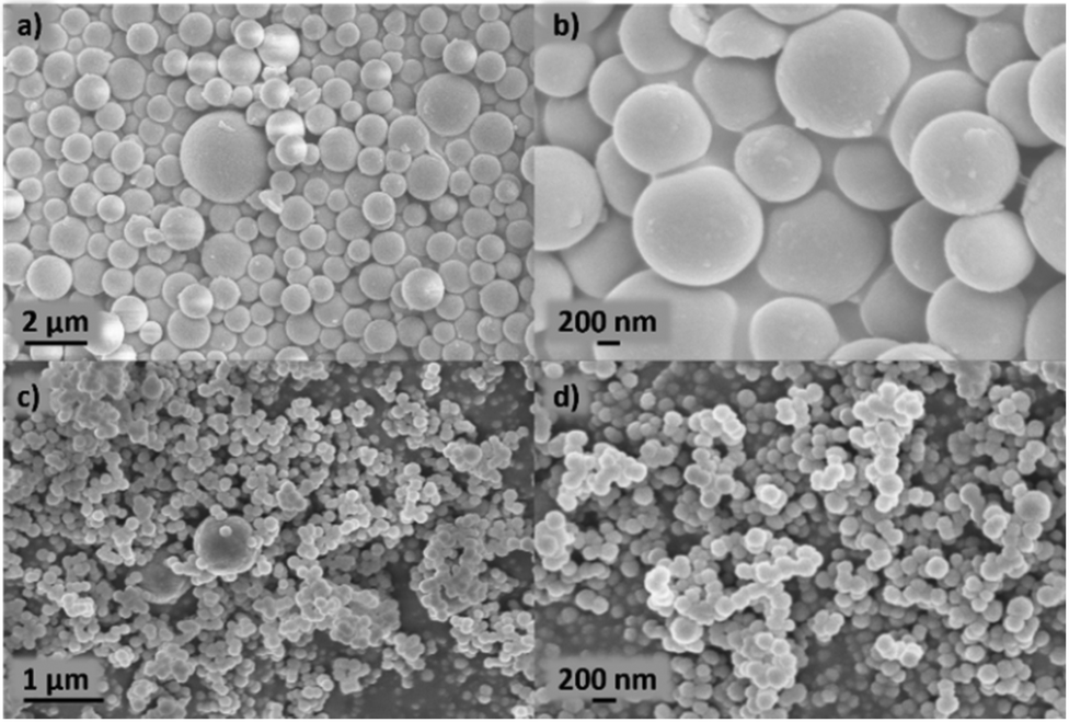 | ||
| Fig. 1 SEM images of HTC-X (a and b) and HTC-XK (c and d). | ||
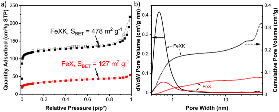 | ||
| Fig. 2 N2 sorption isotherms, where solid and empty squares indicate adsorption and desorption isotherms (a). Pore size distributions and cumulative pore volumes determined using the 2D-NLDFT heterogeneous surface carbon model within SAIEUS software (b). Data for FeX and FeXK. | ||
Finally, from the N2 isotherm (Fig. 2a), the increased quantity of N2 adsorption at high relative pressure (P/P0 > 0.9) in FeXK indicates an increased macropore volume arising between aggregates of FeXK sphere agglomerates.42 This possibly evolves from the smaller kayeaxalate-derived spheres (Fig. S1†). X-ray diffraction (XRD) analysis, conducted to study the crystalline structure of the catalysts, suggests that the change in the morphology of the hydrothermal precursor also affects the chemical nature of the final catalysts (Fig. 3). FeXK presents more accentuated peaks with higher intensity; the sharp peak at 43.8° confirms the presence of Fe (111), although this diffraction peak could point to the presence of Fe3C, nevertheless the diffraction peak at 45°, arising from Fe3C (110) unequivocally proves the formation of carbide species. Additionally, at 51.2°, FeXK displays a Fe (0,2,0) peak. The high intensity of these peaks might hide the presence of the overlapping Iron-Nitrides-related signals, especially in the region 43–44°, as shown in previous work.26 XRD data suggests that the decreased size of HTC-XK versus HTC-X may favor the formation of crystalline Fe-based species that stabilize ORR reaction intermediates and improve the catalytic performance. Further characterization of the materials was carried out using Raman spectroscopy (Fig. S3 and S4†), which showed the presence of two dominant peaks in the first-order spectra. These peaks are centered at approximately 1340 and 1585 cm−1, corresponding to the D and G bands respectively. The G band indicates the presence of graphitic carbon and is present in all graphitic materials, while the D band signifies disorder within the carbon structure.
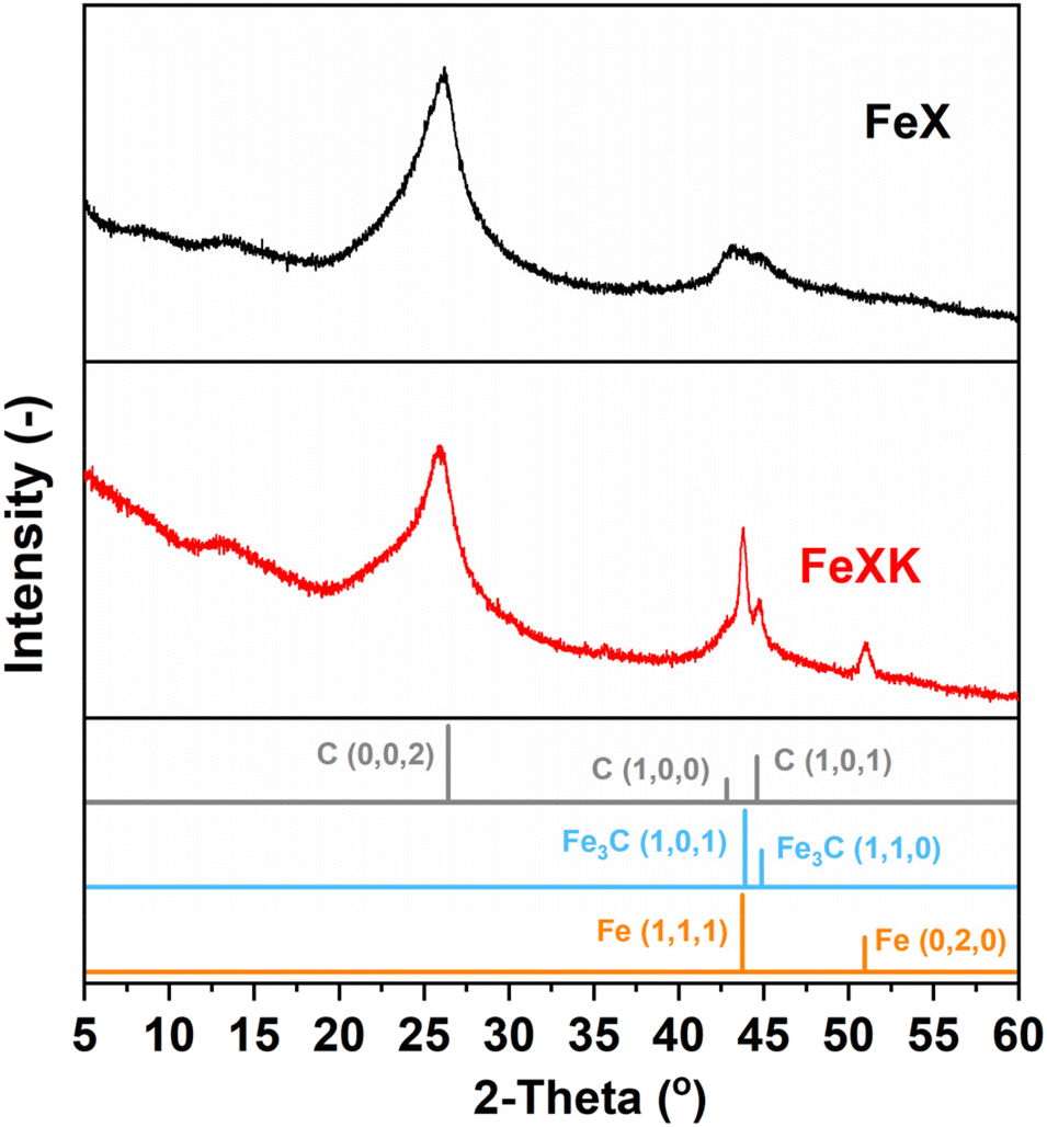 | ||
| Fig. 3 XRD patterns of FeX (a) and FeXK (b) (Iron (96-901-4057) and Iron carbide (00-044-1292) and Carbon (01-075-1621)). | ||
The intensity ratio of the D and G bands (ID/IG) is often used as an indicator of the graphitization degree in carbon materials. The ID/IG values of 1.03 and 1.15 (Table S2†) displayed by FeX and FeXK suggest the presence of nanocrystalline graphitic domains, which is consistent with the broad carbon peaks observed at approximately 26.2 and 44.4°2θ in XRD. For small graphitic crystallite sizes, the ID/IG ratio is correlated to the crystallite size using the Ferrari–Robertson model, which suggests that the ID/IG ratio increases with increasing crystallite size up to a size of 2 nm.43 Therefore, the higher value of 1.15 displayed by FeXK suggests greater graphitic ordering. Also, the variation of the ID/IG value measured at 25 different locations across the sample is greater for FeX (standard deviation of 0.17 compared to 0.05 for FeXK, Table S2†) indicating the non-uniform nature of the carbon structure, with some locations displaying higher graphitic ordering, while other locations have a more disordered structure. The less variable ID/IG values observed in the Raman spectra of FeXK are likely related to the more uniform dispersion of small Fe-based particles throughout the carbon structure. Scanning transmission electron microscopy imaging was then employed to obtain further insights into the morphology, dimensionality, and chemical composition of the Fe-based particles. Fig. 4 and Fig. S5† display the HAADF-STEM images and EDX elemental maps for FeXK and FeX, respectively. Images of FeXK show spherical nanoparticles, approximately 100 nm in diameter, with EDS mapping revealing they contain homogeneous distributions of N, C, O, and Fe. At high magnification, Z-contrast HAADF-STEM imaging reveals bright single atoms and atomic clusters (Fig. 4b), which can be assigned to Fe as the only high atomic number element present. Denser Fe-rich crystalline nanoparticles are also observed with diameters of approximately 10 nm (Fig. 4c). Selected area electron diffraction and Fast Fourier transform (FFT) analysis of high-resolution images from these particles reveals lattice spacings that can be ascribed to the Fe3C phase and/or pure Fe phase (Fig. S6†). FFT analysis along with XRD characterization confirms the presence of both Fe and Fe3C particles as observed in the diffraction peaks at 43.8 and 45 °C (Fig. 3), as well as the Miller indices shown on Fig. S6.†
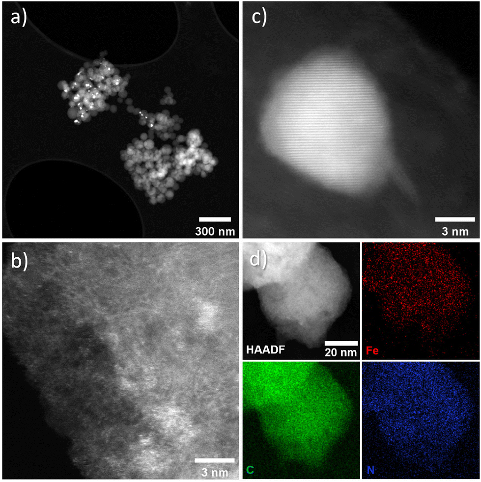 | ||
| Fig. 4 FeXK HAADF-STEM images showing Fe-based particles and atomic Fe species (a–c) and EDX elemental maps for C (green), Fe (red), and N (blue) (d). | ||
FeX is composed of much bigger spherical particles with diameters around 1 μm, which also contain N, C, O, and Fe. The HAADF STEM and EDX elemental mapping reveals that these particles contain Fe-rich nanoparticles of approximately 10 nm diameter, distributed evenly throughout the N, O, C and Fe-containing matrix. High-resolution HAADF-STEM also reveals atomically dispersed Fe species, although these are more difficult to resolve due to the matrix particles’ greater thickness. The atomically dispersed species could be FeNx sites or clusters of FexOy. Due to the small size of the particles and the invisibility of both N and O species relative to the C, O and N support, it is difficult to ascertain the true atomic Fe coordination. These can only be distinguished with certainty via cryo 57Fe Mössbauer spectroscopy.44 The local environment of Fe within FeX was studied by Feng et al.26 by means of X-ray Absorption Spectroscopy where Fe3C was observed, which is in agreement with nanoparticles seen in the HAADF-STEM and XRD data here. The HAADF STEM images of FeX (Fig. S5†), along with its low specific surface area, suggest most of the observed Fe3C nanoparticles are internal to the C–N–O matrix, indicating very low accessibility for the Fe-based species. In contrast, the substantially smaller size of the C–N–O–Fe matrix particles and higher BET surface area of FeXK indicates more efficient exposure of the Fe-based active sites. X-ray photoelectron spectroscopy was employed to provide further insights on the elemental composition of the surface of the prepared catalysts. Carbon, nitrogen, oxygen, and iron were observed in both FeX and FeXK. In terms of chemical composition, substantial differences can be observed between the catalysts (Table S3†). FeX displays a much higher N1s, O1s, and Fe2p surface content than FeXK suggesting a lower electrical conductivity and confirming the presence of Fe-based aggregates. We hypothesize that the higher porosity of FeXK may be responsible for the relatively easier release of nitrogen and oxygen functional groups particularly during the pyrolysis. C1s spectra of both materials display binding energies corresponding to C–C, C–N, and C–O species, while FeX displays an additional chemical species that suggests a higher degree of oxidation in the framework despite the lack of activation step in the O2 atmosphere (Fig. S7†). N1s spectra display four peaks for both materials at 402.2, 400.8, 399.5, and 398.1 eV, indicating the presence of graphitic, pyrrolic, iron–nitrogen, and pyridinic bonds respectively (Fig. S8†). The higher atomic percentage of the pyridinic contribution indicates a pyridinic coordination of the Fe sites within the material, in agreement Fellinger and coworkers who observed that pyridinic active sites are more thermodynamically stable than pyrrolic, which are kinetically preferred above 900 °C.45 Additionally, the amount of Fe in FeXK is 1.46 in wt% (0.32 at%, Fig. S6 and S9†), which is very similar to the Fe content obtained by ICP-MS (1.29 wt%), suggesting that the high porosity of the material exposes most of the Fe with the material resulting in a very similar content in the surface and in the bulk. In contrast, FeX exhibits a higher iron content (3.11 wt%, 0.71 at% according to XPS analysis). As for the nitrogen content, FeX and FeXK yield values of 10.39 wt% and 3.13 wt%, respectively. Such elevated nitrogen content in FeX could be attributed to the retention of C–N based fragments (arising from melamine decomposition) upon pyrolysis.46 We hypothesize that owing to the larger particle diameter and lower porosity of FeX, C–N based fragments are retained in the structure. Meanwhile in the case of FeXK, the smaller particle diameter and higher porosity results in shorter pathways for the release of N-based species during pyrolysis. The lower N and O content within FeXK may entail a higher electrical conductivity, which contributes to an enhanced electrocatalytic activity. While relatively small amounts of nitrogen within a carbon material can increase the electrical conductivity,47 elevated nitrogen contents result in the formation of semiconducting materials, which are not suitable for electrocatalysis. Carbon nitrides for instance, with a predicted stoichiometry of C3N4, display a band gap of 2.7 eV which translates in a low electrical conductivity (between 10−9–10−7 S cm−1);48 C2N covalent organic materials display a band gap of 1.7–1.9 eV,49 and overall nitrogen contents over 20 at% results in negligible electrocatalytic performances even with the presence of Fe single sites.50 Despite the higher levels of N and Fe in FeX, the presence of visible inhomogeneity in the HAADF-STEM images (Fig. S5†) suggests that a significantly higher portion of the iron formed crystalline nanoparticles instead of single atoms sites. O1s spectra suggests that the activation in air employed in the synthesis of FeXK slightly modifies the nature of the functional groups in the surface of the materials (Fig. S10 and Table S4†). Both materials display three different chemical binding energies corresponding to CO bonds, C–O–C/COOH bonds and C–OH groups.51 However, the atomic contribution of C–O–C/COOH bonds in FeXK is substantially higher than in FeX, suggesting that, despite the lower oxygen content within FeXK, the oxygen species change upon air activation. From this characterization, we conclude that the smaller sphere size obtained in the kayexalate-mediated hydrothermal synthesis of xylose-based carbon frameworks strongly determines the physical and chemical properties of the FeNC materials. The higher BET surface area, homogeneous distribution of Fe-based species and suitable N and O content suggest a higher electrocatalytic performance of FeXK compared to FeX. To elucidate whether the increase in surface area translates into more exposed active sites during electrochemical measurements, we determined the double-layer capacitance, denoted as Cdl, from the slopes observed in cyclic voltammograms obtained at different scan rates. This parameter is in fact directly proportional to the electrochemically active surface area. As illustrated in Fig. S11† the Cdl of FeXK surpasses that of FeX by more than twofold (181.1 mF cm−2vs. 84.5 mF cm−2), underscoring the efficacy of kayexalate as a porogen for tailoring the surface area of carbon-based electrocatalysts.
The electrocatalytic activity for the ORR was then screened in alkaline electrolyte (0.1 M KOH) and compared to that of a commercial FeNC material (Pajarito Powder PMFD14401). The coexistence of Fe–Nx and Fe3C has been found to significantly enhance the catalytic performance of the ORR, as shown in several studies.52–54 The theoretical research (DFT) conducted by Reda et al.55 showed that the presence of Fe3C not only stabilizes the intermediates involved in the ORR but also enhances the catalytic performance in alkaline media owing to its electron-donating nature. As illustrated in Fig. 5a, FeXK outperformed FeX across all parameters, including onset potential Eonset (potential at 0.1 mA cm−2, 0.84 and 0.90 V for FeX and FeXK, respectively), half-wave potential E1/2 (0.70 V and 0.80 V) and limiting current density Jlim (−3.68 and −5.36 mA cm−2). The relative performance improvement was substantial across the entire potential range. The addition of kayexalate led to a higher catalytic activity, with FeXK reaching a kinetic current density Jkin of −3.71 mA cm−2 at 0.8 V vs. RHE and a correspondent kinetic mass activity mkin of 14.30 A g−1. On the other side, FeX only showed values of −0.36 mA cm−2 and 1.45 A g−1. Subsequently, a comparison was made between FeXK and PMFD14401, a commercial FeNC material prepared by means of SiO2 templating and acid etching. PMF D14401 displayed a higher electrocatalytic activity reaching Jkin of −15.7 mA cm−2 and mkin of 60.4 A g−1 at 0.8 ViR-freevs. RHE (Table S5†). However, FeXK displayed a higher current density at more cathodic potentials suggesting improved mass transport to the active site, possibly arising from the higher specific area compared to FeX. While FeXK possesses a lower ORR mkin than PMFD14401, it ranks well in terms of biomass-derived catalysts in the literature (Fig. S12, S13 and Table S6†).
 | ||
| Fig. 5 (a) Third cathodic scan RRDE measurements of FeXK, FeX and PMFD14401 in KOH 0.1 M, at 1600 rpm, 10 mV s−1; loading 0.26 mgcatalyst cm−2, corrected for capacitive background (subtraction of equivalent measurement under N2) and iR-compensation (from EIS). Error in FeXK represent two repeat measurements. (b) Electron Transfer Number and H2O2 production of FeXK, FeX and PMFD14401. Pt ring was biased at 1.27 VRHE and collection efficiency calibrated. | ||
FeXK exhibited high selectivity towards the four electron ORR, as evidenced by the average electron transfer number n = 3.95 (Fig. 5b and Fig. S14†), which remains very similar to that of PMFD14401 in a wide potential range. The selectivity of FeX to four electron ORR was lower, with an average value of the electron transfer number of 3.76. The observed high selectivity of FeXK towards the four electron ORR pathway can be attributed to its greater porosity and BET specific surface area, which led to a greater density of four electron selective active sites and (or) tortuosity changes. As discussed earlier, micropores have previously been proposed to host active FeNx sites;27,28 therefore, a higher micropore volume should lend itself to a higher density of four electron selective sites. Additionally, a greater porosity within FeXK could lead to a higher tortuosity in the catalyst layer, providing a longer residence time for H2O2 generated in the catalyst to be further reduced, resulting in an observed increase in four electron selectivity.
The stability of the catalysts was then tested by recording the electrochemical performance after 1000 and 8000 cyclic voltammetry recorded between 0.8 and 0.4 VRHE in O2, at 100 mV s−1 and with an applied potential of 1.27 VRHE for the Pt ring (Fig. S15a and b†). The kinetic mass activity of FeXK showed a 50% and 84% decrease respectively after 1000 and 8000 cycles, while PMFD14401 showed a decrease of 25% and 46%, respectively (Fig. S15c†). However, the rate of loss of kinetic mass activity at 0.8 V vs. RHE was comparable between FeXK and PMFD14401 from 0–1000 cycles (8.7 and 9.3 mA g−1FeNC cycle−1) and from 1000–8000 cycles (0.5 and 1.1 mA g−1FeNC cycle−1). This suggests a similar degradation mechanism for both FeNC. FeNC can degrade through several pathways, including carbon corrosion,56 reactive oxygen species,57 and active Fe species agglomeration58 or dissolution.59 Due to the low upper potential limit (0.8 VRHE) and room temperature conditions for the accelerated stress test, carbon corrosion should not play a factor56 on the FeNC degradation here. Additionally, reactive oxygen species generated via Fenton reactions have been found to possess short lifetimes in alkaline environments,57 indicating this should not be the main degradation pathway here. Fe agglomeration has previously been mainly observed at T > 60 °C.58 The observed degradation rate in FeXK and PMFD14401 may therefore arise from Fe dissolution, which are known to be dependent on the FeNC preparation method60 and chemical environment and location of the FeNx sites (e.g. in micropores).61
To test the material under the practical high current density conditions of a fuel cell, we employed a GDE setup.62 The previously benchmarked GDE measurement protocol,63 which coupled galvanostatic steps and electrochemical impedance spectroscopy is used in a small area gas-diffusion-electrode cell.64Fig. 6 shows the GDE results obtained for FeXK and PMFD14401. As can be seen, the performance of the FeXK operates at 47 ± 35 and 57 ± 12 mV below state-of-the-art commercial PMFD14401 at 0.25 and 2 A cm−2, respectively. While the results obtained with iR-correction and normalized per mass are very similar, the uncorrected performance of FeXK decreases compared with that of PMFD14401 which may arise from the unoptimized N and O content within the catalyst, leading to low electronic conductivity and high charge transfer resistance. Still, FeXK demonstrates the ability to operate at practical current densities (−2 A cm−2), holding promise as a suitable xylose-derived catalyst in AEMFCs.
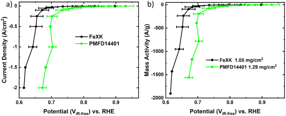 | ||
| Fig. 6 GDE measurement in cathodic direction of FeXK and PMFD14401 (loading 1.05 mg cm−2 and 1.29 mg cm−2 respectively) in KOH 1 M (a) iR-corrected for electrolyte resistance (100% post correction from phase angle closest to 0 in high-frequency region >1000 Hz). (b) and after normalization to catalyst loading. Error bars represent two repeat measurements. | ||
Conclusions
In summary, we have prepared microporous, xylose-derived FeNC oxygen reduction electrocatalysts by introducing small amounts of polystyrene sulfonate (kayexalate) during the hydrothermal carbonization and its subsequent activation and pyrolysis. The negatively charged additive prevents particle self-aggregation, resulting in a 10-fold reduction in particle size. Air activation led to a specific surface area four times higher after high-temperature pyrolysis in the presence of melamine and FeCl2 (478 m2 g−1vs. 126 m2 g−1). The decreased size of HTC-XK carbon spheres versus HTC-X promotes the formation of crystalline Fe-based species, as confirmed by XRD, Raman and STEM, which could enhance the stabilization of ORR intermediates and catalytic performance. Owing to the high porosity, FeXK outperforms FeX across all electrocatalytic performance parameters, achieving a kinetic mass activity (mkin) of 14.30 A g−1 at 0.8 V vs. RHE compared to 1.45 A g−1 for FeX, along with high selectivity towards the four-electron O2 reduction (n = 3.96) using an RRDE setup. Evaluation with a Gas Diffusion Electrode suggests a performance not too distant from that of the commercial PMFD14401, made by silica templating. While the literature reports catalysts with superior performance derived from biomass, they often involve complex activating or templating agents, limiting scalability. This work provides a sustainable, scalable, alternative for the preparation of microporous FeNC catalysts using biomass resources and abundant nitrogen and iron sources, without the need for alkaline activating agents. While currently the ORR performance of FeXK is limited by the relatively small surface area and the presence of Fe-based aggregates, future efforts will focus on: (1) optimizing the type and content of nitrogen, and employing different C–N building blocks, such as phenanthroline. (2) The utilization of alternative biomass resources such as lignin, haemoglobin or fructose. (3) The screening of different activation processes alternative to air pyrolysis, such as CO2 or steam activation.Author contributions
L. M. carried out the synthesis, characterization and electrochemical testing, elaborated an initial draft and led the conceptualization. A. P. co-designed the experiment, provided supervision, assisted in the materials characterization and electrochemical testing and aided in the elaboration of the manuscript. S. K. performed the GDE measurements and aided in the elaboration of the manuscript. R. H. performed Raman measurements and aided in the elaboration of the manuscript. R. C. performed TEM analysis, M. W. assisted with the electrochemical testing and materials characterization. S.J.H. provided supervision, funding and assisted in the elaboration of the manuscript. J. B. co-designed the experiment, provided supervision, aided with materials characterization and assisted with the elaboration of the manuscript.Conflicts of interest
We declare no conflicts of interest.Acknowledgements
We would like to thank Dr Alain Li and Prof. Matthias Arenz for fruitful discussion on the synthesis and GDE testing, respectively. We thank Lisa Pierinet from Symbio for providing Pajarito Powder PMFD14401. A. P. thanks the EPSRC Centre for Doctoral Training in the Advanced Characterisation of Materials (grant number EP/L015277/1). J. B. acknowledges financial support from Imperial College London through the Imperial College Research Fellowship. S. K. acknowledges the financial support from Imperial College London through the Chemical Engineering Department PhD scholarship.References
- H. Yang, X. Han, A. I. Douka, L. Huang, L. Gong, C. Xia, H. S. Park and B. Y. Xia, Adv. Funct. Mater., 2021, 31, 2007602 CrossRef CAS.
- Y. Yang, C. R. Peltier, R. Zeng, R. Schimmenti, Q. Li, X. Huang, Z. Yan, G. Potsi, R. Selhorst, X. Lu, W. Xu, M. Tader, A. V. Soudackov, H. Zhang, M. Krumov, E. Murray, P. Xu, J. Hitt, L. Xu, H.-Y. Ko, B. G. Ernst, C. Bundschu, A. Luo, D. Markovich, M. Hu, C. He, H. Wang, J. Fang, R. A. J. DiStasio, L. F. Kourkoutis, A. Singer, K. J. T. Noonan, L. Xiao, L. Zhuang, B. S. Pivovar, P. Zelenay, E. Herrero, J. M. Feliu, J. Suntivich, E. P. Giannelis, S. Hammes-Schiffer, T. Arias, M. Mavrikakis, T. E. Mallouk, J. D. Brock, D. A. Muller, F. J. DiSalvo, G. W. Coates and H. D. Abruña, Chem. Rev., 2022, 122, 6117–6321 CrossRef CAS PubMed.
- S. Siahrostami, A. Verdaguer-Casadevall, M. Karamad, D. Deiana, P. Malacrida, B. Wickman, M. Escudero-Escribano, E. A. Paoli, R. Frydendal, T. W. Hansen, I. Chorkendorff, I. E. L. Stephens and J. Rossmeisl, Nat. Mater., 2013, 12, 1137–1143 CrossRef CAS PubMed.
- X. Wang, Z. Li, Y. Qu, T. Yuan, W. Wang, Y. Wu and Y. Li, Chem, 2019, 5, 1486–1511 CAS.
- A. Pedersen, J. Pandya, G. Leonzio, A. Serov, A. Bernardi, I. Stephens, M.-M. Titirici, C. Petit and B. Chachuat, Green Chem., 2023, 25, 10458–10471 RSC.
- M. Gong, A. Mehmood, B. Ali, K.-W. Nam and A. Kucernak, ACS Catal., 2023, 13, 6661–6674 CrossRef CAS PubMed.
- X. Gao, L. He, H. Yu, F. Xie, Y. Yang and Z. Shao, Int. J. Hydrogen Energy, 2020, 45, 23353–23367 CrossRef CAS.
- S. Gottesfeld, D. R. Dekel, M. Page, C. Bae, Y. Yan, P. Zelenay and Y. S. Kim, J. Power Sources, 2018, 375, 170–184 CrossRef CAS.
- T. Asset and P. Atanassov, Joule, 2020, 4, 33–44 CrossRef CAS.
- A. Pedersen, A. Bagger, J. Barrio, F. Maillard, I. E. L. Stephens and M.-M. Titirici, J. Mater. Chem. A, 2023, 11, 23211–23222 RSC.
- H. Shen, E. Gracia-Espino, J. Ma, H. Tang, X. Mamat, T. Wagberg, G. Hu and S. Guo, Nano Energy, 2017, 35, 9–16 CrossRef CAS.
- C. Zúñiga Loyola and F. Tasca, Curr. Opin. Electrochem., 2023, 40, 101316 CrossRef.
- M. A. Molina-García and N. V. Rees, RSC Adv., 2016, 6, 94669–94681 RSC.
- Y. Mun, S. Lee, K. Kim, S. Kim, S. Lee, J. W. Han and J. Lee, J. Am. Chem. Soc., 2019, 141, 6254–6262 CrossRef CAS PubMed.
- A. Serov, K. Artyushkova and P. Atanassov, Adv. Energy Mater., 2014, 4, 1301735 CrossRef.
- S. G. Peera and C. Liu, Coord. Chem. Rev., 2022, 463, 214554 CrossRef CAS.
- M. Titirici, S. G. Baird, T. D. Sparks, S. M. Yang, A. Brandt-Talbot, O. Hosseinaei, D. P. Harper, R. M. Parker, S. Vignolini, L. A. Berglund, Y. Li, H.-L. Gao, L.-B. Mao, S.-H. Yu, N. Díez, G. A. Ferrero, M. Sevilla, P. Á. Szilágyi, C. J. Stubbs, J. C. Worch, Y. Huang, C. K. Luscombe, K.-Y. Lee, H. Luo, M. J. Platts, D. Tiwari, D. Kovalevskiy, D. J. Fermin, H. Au, H. Alptekin, M. Crespo-Ribadeneyra, V. P. Ting, T.-P. Fellinger, J. Barrio, O. Westhead, C. Roy, I. E. L. Stephens, S. A. Nicolae, S. C. Sarma, R. P. Oates, C.-G. Wang, Z. Li, X. J. Loh, R. J. Myers, N. Heeren, A. Grégoire, C. Périssé, X. Zhao, Y. Vodovotz, B. Earley, G. Finnveden, A. Björklund, G. D. J. Harper, A. Walton and P. A. Anderson, J. Phys. Mater., 2022, 5, 32001 CrossRef.
- J. Barrio, A. Pedersen, S. Favero, H. Luo, M. Wang, S. C. Sarma, J. Feng, L. T. T. Ngoc, S. Kellner, A. Y. Li, A. B. Jorge Sobrido and M.-M. Titirici, Chem. Rev., 2023, 123, 2311–2348 CrossRef CAS PubMed.
- Y. Feng, J. Jiang, Y. Xu, S. Wang, W. An, Q. Chai, U. H. Prova, C. Wang and G. Huang, Carbon, 2023, 211, 118105 CrossRef CAS.
- E. Commission and J. R. Centre, Brief on agricultural biomass production, Publications Office, 2018 Search PubMed.
- B. Hu, K. Wang, L. Wu, S.-H. Yu, M. Antonietti and M.-M. Titirici, Adv. Mater., 2010, 22, 813–828 CrossRef CAS PubMed.
- M.-M. Titirici and M. Antonietti, Chem. Soc. Rev., 2010, 39, 103–116 RSC.
- S. Prasad, A. Singh and H. C. Joshi, Resour., Conserv. Recycl., 2007, 50, 1–39 CrossRef.
- B. Diwan, D. Mukhopadhyay and P. Gupta, in Biovalorisation of Wastes to Renewable Chemicals and Biofuels, ed. N. Krishnaraj Rathinam and R. K. Sani, Elsevier, 2020, pp. 219–242 Search PubMed.
- A. Y. Li, A. Pedersen, J. Feng, H. Luo, J. Barrio, J. Roman, K. K. Hii and M. M. Titirici, Green Chem., 2022, 24, 7574–7583 RSC.
- J. Feng, R. Cai, E. Magliocca, H. Luo, L. Higgins, G. L. F. Romario, X. Liang, A. Pedersen, Z. Xu, Z. Guo, A. Periasamy, D. Brett, T. S. Miller, S. J. Haigh, B. Mishra and M. M. Titirici, Adv. Funct. Mater., 2021, 31, 2102974 CrossRef CAS.
- V. Armel, S. Hindocha, F. Salles, S. Bennett, D. Jones and F. Jaouen, J. Am. Chem. Soc., 2017, 139, 453–464 CrossRef CAS PubMed.
- X. Wan, X. Liu, Y. Li, R. Yu, L. Zheng, W. Yan, H. Wang, M. Xu and J. Shui, Nat. Catal., 2019, 2, 259–268 CrossRef CAS.
- J. Pampel, A. Mehmood, M. Antonietti and T.-P. Fellinger, Mater. Horiz., 2017, 4, 493–501 RSC.
- J. Barrio, A. Pedersen, S. C. Sarma, A. Bagger, M. Gong, S. Favero, C.-X. X. Zhao, R. Garcia-Serres, A. Y. Li, Q. Zhang, F. Jaouen, F. Maillard, A. Kucernak, I. E. L. L. Stephens and M.-M. M. Titirici, Adv. Mater., 2023, 35, 2211022 CrossRef CAS PubMed.
- S. Juvanen, A. Sarapuu, S. Vlassov, M. Kook, V. Kisand, M. Käärik, A. Treshchalov, J. Aruväli, J. Kozlova, A. Tamm, J. Leis and K. Tammeveski, ChemElectroChem, 2021, 8, 2288–2297 CrossRef CAS.
- Q. Wang, Y. Yang, F. Sun, G. Chen, J. Wang, L. Peng, W.-T. Chen, L. Shang, J. Zhao, D. Sun-Waterhouse, T. Zhang and G. I. N. Waterhouse, Adv. Energy Mater., 2021, 11, 2100219 CrossRef CAS.
- Q.-C. Cao, X.-B. Ding, F. Li, Y.-H. Qin and C. Wang, J. Colloid Interface Sci., 2020, 576, 139–146 CrossRef CAS PubMed.
- A. Mehmood, J. Pampel, G. Ali, H. Y. Ha, F. Ruiz-Zepeda and T.-P. Fellinger, Adv. Energy Mater., 2018, 8, 1701771 CrossRef.
- M. M. Hossen, K. Artyushkova, P. Atanassov and A. Serov, J. Power Sources, 2018, 375, 214–221 CrossRef CAS.
- M. Mazzucato, G. Daniel, A. Mehmood, T. Kosmala, G. Granozzi, A. Kucernak and C. Durante, Appl. Catal., B, 2021, 291, 120068 CrossRef CAS.
- Y. Gong, Z. Wei, J. Wang, P. Zhang, H. Li and Y. Wang, Sci. Rep., 2014, 4, 6349 CrossRef CAS PubMed.
- C. Wei, R. R. Rao, J. Peng, B. Huang, I. E. L. Stephens, M. Risch, Z. J. Xu and Y. Shao-Horn, Adv. Mater., 2019, 31, 1806296 CrossRef PubMed.
- W. Xing, G. Yin and J. Zhang, Rotating Electrode Methods and Oxygen Reduction Electrocatalysts, 2014, vol. 6 Search PubMed.
- D. M. Morales and M. Risch, JPhys Energy, 2021, 3, 034013 CrossRef CAS.
- A. Karmakar and S. Kundu, Mater. Today Energy, 2023, 33, 101259 CrossRef CAS.
- T. Soboleva, X. Zhao, K. Malek, Z. Xie, T. Navessin and S. Holdcroft, ACS Appl. Mater. Interfaces, 2010, 2, 375–384 CrossRef CAS PubMed.
- A. C. Ferrari and J. Robertson, Phys. Rev. B: Condens. Matter Mater. Phys., 2000, 61, 14095–14107 CrossRef CAS.
- U. I. Kramm, L. Ni and S. Wagner, Adv. Mater., 2019, 31, 1805623 CrossRef PubMed.
- D. Menga, J. L. Low, Y.-S. Li, I. Arčon, B. Koyutürk, F. Wagner, F. Ruiz-Zepeda, M. Gaberšček, B. Paulus and T.-P. Fellinger, J. Am. Chem. Soc., 2021, 143, 18010–18019 CrossRef CAS PubMed.
- B. Jürgens, E. Irran, J. Senker, P. Kroll, H. Müller and W. Schnick, J. Am. Chem. Soc., 2003, 125, 10288–10300 CrossRef PubMed.
- D.-S. Yang, S. Chaudhari, K. P. Rajesh and J.-S. Yu, ChemCatChem, 2014, 6, 1236–1244 CrossRef CAS.
- J. Barrio, L. Lin, P. Amo-Ochoa, J. Tzadikov, G. Peng, J. Sun, F. Zamora, X. Wang and M. Shalom, Small, 2018, 14, 1800633 CrossRef PubMed.
- J. Mahmood, E. K. Lee, M. Jung, D. Shin, I.-Y. Jeon, S.-M. Jung, H.-J. Choi, J.-M. Seo, S.-Y. Bae, S.-D. Sohn, N. Park, J. H. Oh, H.-J. Shin and J.-B. Baek, Nat. Commun., 2015, 6, 6486 CrossRef CAS PubMed.
- J. Barrio, A. Pedersen, J. Feng, S. C. Sarma, M. Wang, A. Y. Li, H. Yadegari, H. Luo, M. P. Ryan, M.-M. Titirici and I. E. L. Stephens, J. Mater. Chem. A, 2022, 10, 6023–6030 RSC.
- G.-F. Han, F. Li, W. Zou, M. Karamad, J.-P. Jeon, S.-W. Kim, S.-J. Kim, Y. Bu, Z. Fu, Y. Lu, S. Siahrostami and J.-B. Baek, Nat. Commun., 2020, 11, 2209 CrossRef CAS PubMed.
- Y. Chen, X. Kong, Y. Wang, H. Ye, J. Gao, Y. Qiu, S. Wang, W. Zhao, Y. Wang, J. Zhou and Q. Yuan, Chem. Eng. J., 2023, 454, 140512 CrossRef CAS.
- C. Chu, J. Liu, L. Wei, J. Feng, H. Li and J. Shen, Int. J. Hydrogen Energy, 2023, 48, 4492–4502 CrossRef CAS.
- M. Wang, Y. Yang, X. Liu, Z. Pu, Z. Kou, P. Zhu and S. Mu, Nanoscale, 2017, 9, 7641–7649 RSC.
- M. Reda, H. A. Hansen and T. Vegge, ACS Catal., 2018, 8, 10521–10529 CrossRef CAS.
- C. H. Choi, C. Baldizzone, J.-P. Grote, A. K. Schuppert, F. Jaouen and K. J. J. Mayrhofer, Angew. Chem., Int. Ed., 2015, 54, 12753 CrossRef CAS PubMed.
- G. Bae, M. W. Chung, S. G. Ji, F. Jaouen and C. H. Choi, ACS Catal., 2020, 10, 8485 CrossRef CAS.
- K. Kumar, T. Asset, X. Li, Y. Liu, X. Yan, Y. Chen, M. Mermoux, X. Pan, P. Atanassov, F. Maillard and L. Dubau, ACS Catal., 2021, 11, 484 CrossRef CAS.
- Y.-P. Ku, K. Ehelebe, A. Hutzler, M. Bierling, T. Böhm, A. Zitolo, M. Vorokhta, N. Bibent, F. D. Speck, D. Seeberger, I. Khalakhan, K. J. J. Mayrhofer, S. Thiele, F. Jaouen and S. Cherevko, J. Am. Chem. Soc., 2022, 144, 9753 CrossRef CAS PubMed.
- P. G. Santori, F. D. Speck, J. Li, A. Zitolo, Q. Jia, S. Mukerjee, S. Cherevko and F. Jaouen, J. Electrochem. Soc., 2019, 166, F3311 CrossRef CAS.
- R. Chenitz, U. I. Kramm, M. Lefèvre, V. Glibin, G. Zhang, S. Sun and J.-P. Dodelet, Energy Environ. Sci., 2018, 11, 365 RSC.
- V. Gridin, J. Du, S. Haller, P. Theis, K. Hofmann, G. K. H. Wiberg, U. I. Kramm and M. Arenz, Electrochim. Acta, 2023, 444, 142012 CrossRef CAS.
- K. Ehelebe, N. Schmitt, G. Sievers, A. W. Jensen, A. Hrnjić, P. Collantes Jiménez, P. Kaiser, M. Geuß, Y.-P. Ku, P. Jovanovič, K. J. J. Mayrhofer, B. Etzold, N. Hodnik, M. Escudero-Escribano, M. Arenz and S. Cherevko, ACS Energy Lett., 2022, 7, 816–826 CrossRef CAS.
- G. K. H. Wiberg, S. Nösberger and M. Arenz, Curr. Opin. Electrochem., 2022, 36, 101129 CrossRef.
Footnote |
| † Electronic supplementary information (ESI) available. See DOI: https://doi.org/10.1039/d3gc04645a |
| This journal is © The Royal Society of Chemistry 2024 |