
 Open Access Article
 This Open Access Article is licensed under a
 Creative Commons Attribution 3.0 Unported Licence
A bi-functional air electrode developed from a dual-MOF strategy for high-performance zinc–air batteries†
Yasir
Arafat
ab,
Muhammad Rizwan
Azhar
b,
Yijun
Zhong
 a,
Xiaomin
Xu
a,
Moses O.
Tadé
a and
Zongping
Shao
*a
a,
Xiaomin
Xu
a,
Moses O.
Tadé
a and
Zongping
Shao
*a
aWA School of Mines: Minerals, Energy and Chemical Engineering (WASM-MECE), Curtin University, Perth, WA 6102, Australia. E-mail: zongping.shao@curtin.edu.au
bSchool of Engineering, Edith Cowan University, 270 Joondalup Drive, Joondalup, WA 6027, Australia
First published on 19th April 2024
Abstract
A durable, high-performing and cost-effective bi-functional catalyst toward oxygen reduction/evolution reactions (ORR/OER) is the key towards the practical application of Zn–air batteries (ZABs). Here, we report a new concept of combining pristine and carbonized MOFs for developing a bifunctional electrocatalyst for ZABs, where the pristine MOF acts as a support for the OER catalysts and the carbonized MOF acts as the ORR catalyst and enhances the electronic conductivity. By electroless NiP-plating over the surface of the Fe-containing 3D MOF (MIL-100), the catalyst shows superior activity for the OER, delivering a current density of 10 mA cm−2 at an overpotential of 295 mV together with a low Tafel slope of 62 mV dec−1. A 3D porous MOF serves as a substrate for growing NiP with maximal exposed active sites and the iron in the MOF interacts with NiP to further boost the intrinsic OER activity. Subsequently, we introduce carbonized ZIF-67 (C-ZIF-67) into NiP-MIL-100 to build a bifunctional catalyst, where C-ZIF-67 not only provides ORR catalytic activity but also creates a synergetic effect with NiP-MIL-100, and to expedite the charge/mass transfer. Using this air electrode for ZABs, an excellent bifunctionality with a small potential gap (0.78 V), a high peak power density (203 mW cm−2) and robust cycling over a period of 500 h were achieved.
Broader contextWe have devised a facile strategy to fabricate bifunctional (oxygen evolution and oxygen reduction reactions) electrocatalysts for zinc–air batteries by a combination of NiP-plated pristine metal–organic frameworks (MOFs) and a carbonized MOF (C-ZIF-67). We have employed a pristine MOF, i.e. MIL-100, for the first time to serve as a 3D scaffold for NiP plating. On one hand, the MOF served as a 3D carrier for NiP to expose maximum OER active sites and on the other hand, it endows uniformly distributed Fe metal nodes over the MOF surface, which activated the NiP active sites, leading to excellent oxygen evolution activity. As NiP-plated MIL-100 and ZIF-derived Co–N–C efficiently served to accelerate the oxygen evolution and oxygen reduction reactions, this MOF can be employed as the cathode material to other batteries, for instance, lithium–air batteries and water splitting reactions. Moreover, 3D pristine MOFs may be employed as a host and activator for various electrocatalysts in energy applications. Thus, this cutting-edge synthesis strategy will usher a new avenue for the fabrication of a variety of energy materials with superior activity and stability. Consequently, this work will contribute to attaining the United Nations’ sustainable development goals. |
Introduction
The ever-increasing environmental awareness and global energy demands have prompted the communities to switch to more sustainable energies, for example, wind, hydro and solar energies.1 Although sustainable energies occur ubiquitously, they are unfortunately intermittent. To ensure an uninterrupted energy supply from sustainable resources, it is imperative to integrate some batteries to reconcile the energy generation and distribution. Recently, zinc–air batteries (ZABs) have garnered tremendous interest owing to their ultrahigh theoretical energy density (1086 W h kg−1), low cost, and safety.2 Rechargeable ZABs are capable of meeting the energy requirement for portable electronic devices, electric vehicles, and grid-scale energy storage.3 As a result, primary (non-rechargeable) zinc–air batteries have been successfully well-placed on a commercial scale. However, secondary (rechargeable) zinc–air batteries have not been commercialized yet. As a matter of fact, the air electrodes beset under the influence of some technical barriers, which pose the reversibility and cycling stability of ZABs. The unique half-open assembly of ZABs entails the designing of air electrodes, which can deliver fast kinetics for the oxygen reduction reaction (ORR) during discharge and the oxygen evolution reaction (OER) during charge. As ORR and OER activities occur at different active sites and the samples undergo different pathways,4 it is quite challenging to design an air electrode that can achieve the high performance of ZABs.To develop rechargeable ZABs, the OER/charging air cathode plays a major role. Transition metal phosphides, NiP nanoparticles, in particular, have arisen as favourable electrocatalysts with excellent OER activity in alkaline solutions.5–13 Actually, they are recognized as OER pre-catalysts, which undergo an in situ transformation to the corresponding oxides and oxyhydroxides via anodic oxidation.14–16 The partially charged Niδ+ and Pδ− atoms in NiP tend to generate OER active NiOOH species and phosphate-based phases, respectively.17 Nevertheless, the major bottleneck associated with the application of NiP is their strong tendency towards agglomeration during extended electrocatalytic activity, thus exposing the limited active sites and thereby leading to poor stability.18–21 As a result, despite the excellent OER activity, it is challenging to employ NiP in the pristine form for rechargeable ZABs to realize stable performance. For instance, Wang et al. recently applied a NiP-based air cathode for ZABs,22 and although it displayed excellent initial OER activity, the charge/discharge cycling sustained only for 20 h. Similarly, He et al. designed NPO/NixPy@NF-HPCs by growing NixPy and hierarchical porous flower-shaped carbon nanosheets on a Ni foam surface, which displayed very poor stability for only 10 h with a large charge/discharge voltage gap.23 In the similar fashion, Huo et al. fabricated an air cathode consisting of a porous Ni-foam-templated structure of carbon nanosheets decorated with CoP nanoparticles,24 which displayed excellent activity with limited stability of 135 h. Consequently, it is vital to fabricate a NiP catalyst with some suitable substrate that could expose sufficient active sites and yet maintain a stable performance. On the other hand, it has also been found that the OER activity of NiP may be further enhanced by some activators such as Fe.7,12,16 Actually, the Fe species enhance the OER activity by suppressing the metal oxidation step and promoting the reduction of metal step, leading to the evolution of oxygen.25 Besides, the presence of Fe also promotes the electrical conductivity of the materials by partial charge transfer and modulation of the electrochemical redox process.26 Recently, three-dimensional (3D) porous materials such as carbon cloth, Cu and Ni foam have been tremendously utilized as supports.27,28 However, these materials undergo corrosion at a higher current density in alkaline media, leading to the unsatisfactory catalytic performance.29–31
Recently, metal–organic frameworks (MOFs) have garnered a great deal of interest in energy applications such as fuel cells, water electrolysis and metal–air batteries.32 MOFs are porous materials with a high surface area, designed by self-assembly of transition metal ions and an organic linker into a periodic 3D network. The direct application of MOFs as electrocatalysts is challenging since they are usually electronic insulators; however, they have the potential to serve as a substrate and provide metal ions to form composites that manifest the enhanced electrocatalytic activity of the main active component. On the other hand, MOFs can also serve as a precursor to form conductive porous metal–carbon composites through pyrolysis, which have demonstrated high ORR activity, even comparable to that of precious metal-based (Pt/C) catalysts.33 Due to the different active sites for the ORR and OER, it is usually difficult to develop a single-phase catalyst that shows high activity for both reactions. However, the formation of a composite provides new opportunities for the development of bifunctional electrocatalysts.
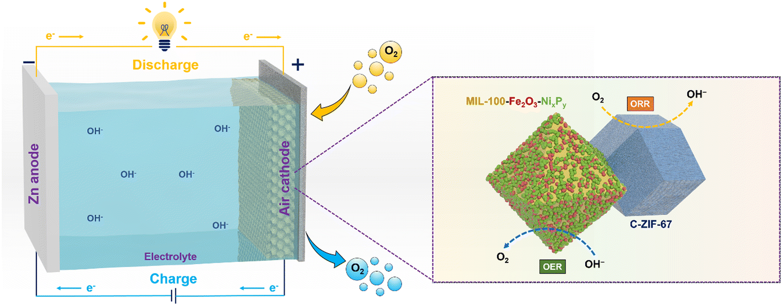
Herein, we introduce a dual-MOF concept to develop a durable, cost-effective, and high-performing bifunctional electrocatalyst as an air electrode for ZABs, in which one MOF acts as a support to deposit OER catalysts to maximize the exposed active sites and to inhibit aggregation, and the other MOF acts as a precursor for producing carbonized samples as the ORR active catalyst and enhances the electronic conductivity. Specifically, we deposit NiP over the wall of the iron-containing MOF, i.e. MIL-100, through electroless-plating, forming NiP@MIL-100, which shows highly exposed active sites. In addition, the interaction of iron in the MOF with a NiP surface area further boosts the OER activity of the catalyst. To introduce ORR activity, we use ZIF-67 as a precursor to create a catalyst through carbonization (C-ZIF-67). We then combine NiP@MIL-100 and carbonized C-ZIF-67 to form a composite, which may offset each other's deficiencies and culminate into a high performance bi-functional (OER/ORR) air electrode for ZABs. NiP@MIL-100 + C-ZIF-67 (50![[thin space (1/6-em)]](https://www.rsc.org/images/entities/char_2009.gif) :50 by weight) was found to be an optimal catalyst. By integrating it into a ZAB as an air cathode, excellent bi-functional activity and stability, a small voltage gap of 0.78 V over a period of 500 h and a high power density of 203 mW cm−2 were demonstrated. This work will usher a new avenue for the fabrication of a 3D bi-functional (OER/ORR) air electrode with superior activity and stability and pave the way for their commercial applications.
:50 by weight) was found to be an optimal catalyst. By integrating it into a ZAB as an air cathode, excellent bi-functional activity and stability, a small voltage gap of 0.78 V over a period of 500 h and a high power density of 203 mW cm−2 were demonstrated. This work will usher a new avenue for the fabrication of a 3D bi-functional (OER/ORR) air electrode with superior activity and stability and pave the way for their commercial applications.
Experimental
Materials and methods
Analytical grade chemicals were procured from Sigma Aldrich, Australia with ≥99.5% purity and were employed with no further purification. Specifically, MIL-96 and MIL-100 were selected as substrates. For their synthesis, the following precursors were employed: aluminium nitrate nonahydrate (Al(NO3)3·9H2O), iron chloride hexahydrate (FeCl3·6H2O) and benzene tricarboxylic acid (BTC). In the case of NiP electroless plating, nickel chloride hexahydrate (NiCl2·6H2O), sodium succinate (C4H4Na2O4), sodium hypophosphite (NaH2PO2) and sodium chloride (NaCl) were used for their respective roles as precursor chemical reagents for Ni2+ ions, complexing agent, reducing agent and surface activation, respectively. For the synthesis of zeolite imidazolate frameworks (ZIFs), cobalt nitrate hexahydrate (Co(NO3)2·6H2O) was used as the metal node, 2-methylimidazole (2-MIM) as the organic ligand and pluronic F-127 as the surfactant.Synthesis of MIL-96 and MIL-100
The detailed synthesis procedure of MOFs is reported in the literature.34,35 In a typical hydrothermal synthesis procedure, MIL-96 was synthesized by adding 19.833 mmol of Al(NO3)3·9H2O and 4.18 mmol of BTC to 27 mL of DI H2O. The mixture was stirred for 30 min and then transferred to a 125 mL autoclave for heating at 220 °C for 48 h. Then, the autoclave was cooled down naturally, and crystals of MIL-96 were separated through filtration. Similarly, MIL-100(Fe) was prepared by mixing 53.38 mmol of FeCl3·6H2O with 23.98 mmol of BTC in 36 mL of DI H2O and heated in an oven at 160 °C for 15 h.Electroless plating of NiP over MIL-96 and MIL-100
For the NiP coating experiment, a fixed amount of nickel chloride hexahydrate (NiCl2·6H2O), sodium chloride (NaCl), sodium succinate (C4H4Na2O4) and sodium hypophosphite (NaH2PO2) were added to deionized water and stirred until they are completely dissolved. The pH value of the as-prepared solution was 5.65. For the activation experiment, palladium chloride (PdCl2) was dissolved in DI water to prepare a 250 ppm solution, and its pH value was modified to about 2.0 by employing NaOH and 0.1 M HCl. The MOF substrates namely MIL-96 and MIL-100 crystals were activated by immersing them into PdCl2 solution for 5 min. Subsequently, chemisorbed Pd2+ ions served as nucleation sites and allowed the surface of the substrate to adsorb H+, Ni2+ and H2PO2−. As soon as the reduction of Ni2+ started, it promoted further reduction of Ni2+ in the solution and the formation of Ni–P, a binary alloy.After the activation, substrates were separated by centrifugation from the PdCl2 solution. Subsequently, the substrates were added to a pre-heated (85 ± 2 °C) coating bath solution. The rapid evolution of gas bubbles started immediately, and the colour of the solution transformed from green to grey. The reaction was allowed to proceed for 15 min under continuous stirring. The pH of the solution was changed from 5.65 to 2.5 and bubble formation stopped. After the completion of the reaction, the mother liquor was allowed to cool, and particles were separated followed by centrifugation and rinsed with deionized water. Eventually, the NiP-coated substrates were obtained followed by drying at 150 °C after 12 h. Generally, NiP electroless plating proceeds through the following steps (eqn (1)–(4)):
| H2PO2− + H2O → HPO32− + 2Had + H+ | (1) |
| Ni2+ + 2Had → Ni + 2H+ | (2) |
| H2PO2− + Had → H2O + OH− + P | (3) |
| 2Had → H2↑ | (4) |
Synthesis of ZIF-67 and C-ZIF-67
The zeolite imidazolate framework, another MOF, was synthesized as per our previous studies with a little modification.36 Briefly, the metal node precursor, cobalt nitrate and pluronic F-127 as surfactants were dissolved in methanol solvent. Another solution consisting of 2-methylimidazole as the organic ligand and methanol was prepared. Both solutions were dissolved together, while stirring at room temperature. Subsequently, the solution was mixed properly, and ZIF-67 crystals were precipitated and filtered. Finally, the pyrolysis of ZIF-67 crystals was conducted in a tube furnace under an N2 atmosphere at 750 °C at a ramp of 2 °C min−1. The pyrolysis of ZIF-67 crystals was carried out for 2 h, and the catalyst obtained after the pyrolysis was named as C-ZIF-67.Characterization of catalysts
The crystalline phases of catalysts were examined by XRD analysis (D8 Discover, Cu Kα radiation, Bruker AXS) in conjunction with HRTEM (FS200X G2, FEI Talos). The elemental distribution (high-resolution) was obtained using EDS mapping (FEI Talos). The Brunauer–Emmett–Teller (BET) surface area was determined using the Tristar II plus (ASAP 2020 HD88, Micromeritics). The surface chemical states of the catalysts were scrutinized by X-ray photoelectron spectroscopy (XPS).Evaluation of the oxygen electrocatalytic activity
The ORR/OER activities of the air electrodes were evaluated by rotating a disc electrode using a three-electrode glass assembly, i.e. a counter electrode, a working electrode and a reference electrode in an alkaline solution of 0.1 M KOH. The counter electrode consists of a platinum spiral enclosed in a glass tube, the working electrode comprises the glassy carbon electrode with a diameter of 5 mm and the reference electrode is based on Ag/AgCl. NiP-plated pristine MIL-100 powder was mixed with super P carbon at a mass ratio of 5:3. As for C-ZIF-67, it was used without the use of any conductive carbon. In the case of a mixture of NiP-plated pristine MIL-100 and C-ZIF-67, the mass ratio of the mixture with super P carbon was 5:3. The catalyst powder was dispersed in a solution containing absolute ethanol + 5 wt% Nafion 117 at a volume ratio of 9:1 for 1 h in an ultrasonic bath. Eventually, the catalyst ink was cast on the working electrode dropwise to get a mass loading of 0.255 mg of catalyst per cm2. Linear sweep voltammograms were obtained at a scan rate of 5 mV s−1 on a potentiostat (CHI760E, bipotentiostat, USA) with the disc rotating at a speed of 1600 rpm. The potentials were translated from Ag/AgCl to reversible hydrogen electrode (RHE) potentials as follows:| ERHE = E(Ag/Agcl) + 0.199 + 0.0591 × pH |
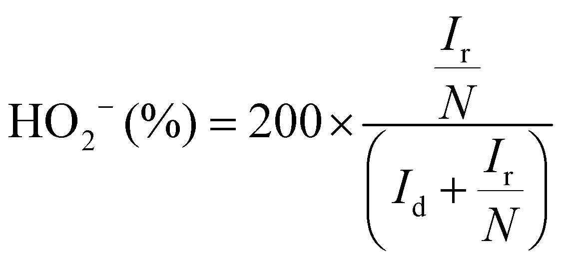
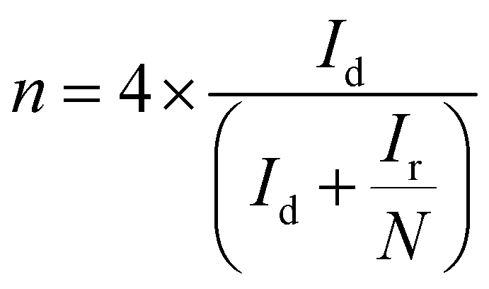
The electron transfer number (n) as well as the peroxide yield (%) were estimated by employing the rotating ring-disk electrode (RRDE) assembly. The RRDE comprised a disc of diameter 5.61 mm, surrounded by a Pt ring with an external diameter of 6.25 mm and an internal diameter of 7.92. The following calculations were applied to evaluate the peroxide yield and the electron transfer number (n), respectively:
Assembly and evaluation of the performance of rechargeable ZABs
The ZAB performance was evaluated through a two-electrode homemade cell, consisting of an air cathode, an alkaline electrolyte [6 M KOH + 0.2 M Zn(Ac)2] and a zinc anode plate. The air cathode was prepared by drop coating of the same catalyst ink prepared earlier on the circular area with a diameter of 8 mm to achieve a catalyst loading of 1 mg cm−2. For comparison, the powder of benchmark 20 wt% Pt/C and IrO2 was prepared by mixing them in the weight ratio of 1:1. The recording of galvanostatic charge/discharge of assembled ZABs was conducted by applying the LANHE CT2001A battery testing system. Moreover, the rest of the electrochemical evaluations were performed using the VSP Biologic potentiostat.
Results and discussion
Physicochemical characterization studies
NiP electroless plating over both Fe and Al-containing MOF substrates (i.e. MIL-100 and MIL-96, respectively) was performed. NiP plating is a self-catalytic redox process that proceeds without the need for an external voltage. It involves NaH2PO2 as a reducing agent and PdCl2 as a catalyst (providing nucleation sites) to activate the MOF substrate because of the insulating nature of pristine MOFs. The electroless process commenced from the deposition of Pd2+ as an activation layer on the MOF substrates, followed by the substitution of Ni2+, which further reacted with P released from the reducing agent to form a NiP layer (Scheme 1).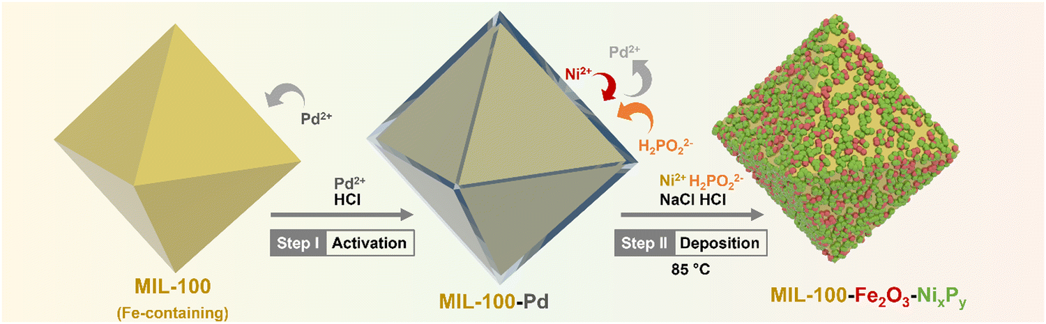 | ||
| Scheme 1 Schematic illustration of the synthesis of NiP-plated MIL-100. | ||
Phase analysis of the NiP@MIL-100 sample was conducted using X-ray diffraction (XRD) as shown in Fig. 1(a). It can be observed that the NiP@MIL-100 sample actually consists of crystalline phases of Ni2P (JCPDS 03-065-1989), Ni12P5 (JCPDS 01-074-1381), Fe2NiP (JCPDS 01-075-1832), Fe2P (JCPDS 00-033-0670) and Fe2O3 (JCPDS 01-089-8103). With regard to the XRD of NiP@MIL-96, as shown in Fig. S1 (ESI†), MIL-96 retained its crystalline nature and phase structure after the NiP plating (Fig. S1, ESI†). It suggests there was negligible chemical interaction between the plated NiP phase and MIL-96. In comparison, MIL-100 (Fig. S2, ESI†) experienced the chemical interaction upon NiP plating (Fig. 1(a)). It indicates that Fe nodes in MIL-100 likely had a strong interaction with the plated NiP phase, with the formation of new phases (e.g. Fe2P and Fe2NiP). With regard to ZIF-67, as shown in Fig. S3 (ESI†), the XRD of pristine ZIF-67 confirms the successful formation of representative ZIF-67 crystals. After the carbonization at 750 °C under an N2 atmosphere, ZIF-67 crystals were transformed into a carbon-based material, Co–N–C (C-ZIF-67). Table S1 (ESI†) shows the specific surface area of the MOF substrates and NiP-plated MOFs. It can be observed that the specific surface area of the samples significantly reduced after the NiP-plating of the MOFs, implying that the pore walls of MOFs were largely covered by the NiP-plating.
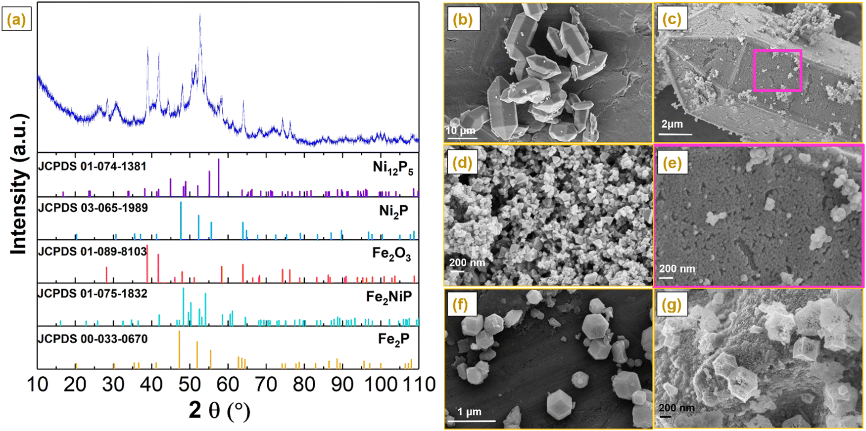 | ||
| Fig. 1 (a) XRD patterns of NiP@MIL-100. Scanning electron microscopy (SEM) images of (b) MIL-96, (c) NiP@MIL-96, (d) NiP@MIL-100, (e) magnified image of the square marked area in (c) and (f) pristine ZIF-67 and (g) C-ZIF-67 crystals after carbonization at 750 °C under an atmosphere of N2. | ||
Scanning electron microscopy (SEM) was performed to evaluate the morphological evolution of pristine and NiP-plated MIL-96 and MIL-100 (Fig. 1(b)–(g)). Pristine MIL-96 displayed a typical morphology of hexagonal crystals with a smooth and clean surface with a size in the range of 2–10 μm (Fig. 1(b)). After the NiP electroless plating, the surface of MIL-96 crystals became rough (Fig. 1(c)). From the magnified SEM image, as shown in Fig. 1(e), well-interconnected and uniformly distributed nanoparticles over the surface were observed. According to Fig. 1(d), the NiP coating also covered the MIL-100 surface in NiP@MIL-100 crystals. In combination with the XRD results, the NiP layer was homogeneously coated over the wall of MOF substrates after the electroless plating. With regard to ZIF-67 crystals, as shown in Fig. 1(f), they take the typical dodecahedron morphology. Upon carbonization, the size of C-ZIF-67 reduced but the morphological shape was retained similar to that of the original ZIF-67 crystals (Fig. 1(g)).
The morphology, composition, and elemental distribution of the NiP@MIL-100 sample were characterized by TEM, selected area electron diffraction (SAED), high angle annular dark-field imaging (HAADF) and EDS chemical mapping. According to the TEM images shown in Fig. 2(a and b), the surface of NiP@MIL-100 crystals was rough and surrounded by the interconnected NiP tiny particles with uniform distribution. In the SAED image shown in Fig. 2(c), the (111), (104), (300), (310), (212), (512), (201), (312) and (321) diffraction planes of NixPy, Fe2P, Fe2NiP, and Fe2O3 phases were detected, in good agreement with the XRD results. According to the HR-TEM images shown in Fig. 2(d)–(h), diffractions with the interplanar spacings of 0.251, 0.223 and 0.169 nm were observed, which correspond well to those of the (104), (111) and (300) crystal planes of Fe2O3, Fe2P and Ni2P. Moreover, the corresponding fast Fourier transformation (FFT) results are also in line with the interplanar spacings. Atomic-scale high angle annular dark-field (HAADF) imaging and energy-dispersive X-ray spectroscopy (EDS) chemical mappings display the uniform distribution of NiP-based particles over the surface of MIL-100 crystals (Fig. 2(i)).
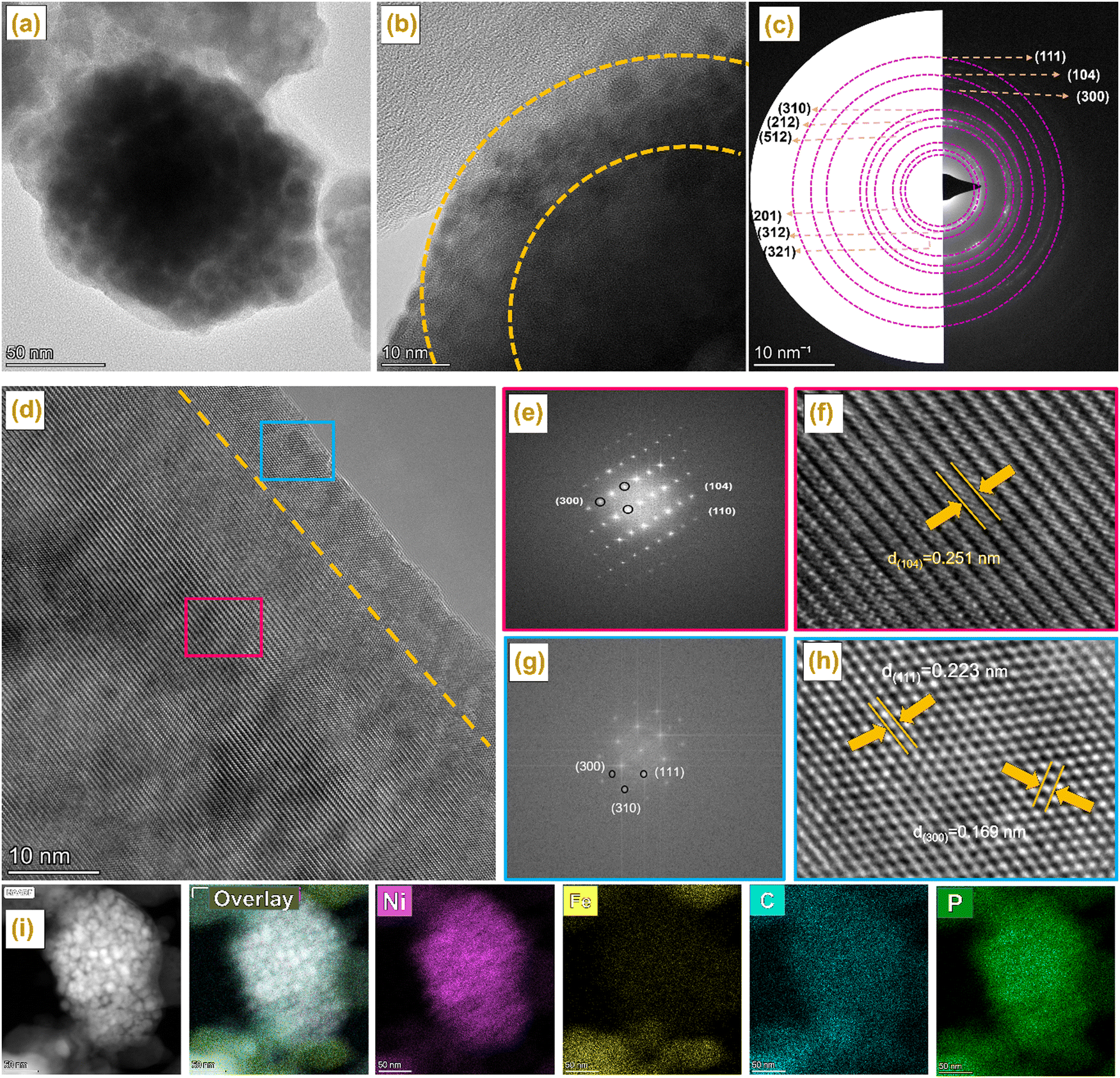 | ||
| Fig. 2 (a, b) TEM of NiP@MIL-100, (c) SAED and (d–h) HRTEM of NiP@MIL-100, HAADF-STEM images of the NiP@MIL-100 sample and its corresponding elemental mapping images. | ||
Surface-sensitive photoelectron spectroscopy (XPS) was conducted to determine the chemical states and surface chemistry of the as-synthesized NiP, NiP@MIL-96, and NiP@MIL-100 samples as shown in Fig. 3 and the peak positions are given in Table S3 (ESI†). The survey spectra shown in Fig. S4(a)–(c) (ESI†) illustrate the presence of Ni and P elements and thus confirm the successful plating of NiP on the MOF substrates. Fig. 3(a) shows the high-resolution Ni 2p XPS spectrum of pristine NiP, which consisted of two peaks namely 2p1/2 and 2p3/2. More precisely, these peaks were deconvoluted into three peaks centred at 853.82, 855.15 and 861.5 eV for Ni 2p3/2. As the zero valence state of Ni is at 852 eV, the corresponding energy level might be attributed to Niδ+, oxidized Ni (Ni2+ ion), and satellite species for the Ni 2p3/2 peak, respectively.37 Likewise, the peaks at 871.5 eV, 873.4 eV and 878.6 eV were also ascribed to Niδ+, oxidized Ni and the shake-up satellites of Ni 2p1/2, respectively. Fig. 3(d) shows the high-resolution P 2p XPS spectrum of pristine NiP, which can be deconvoluted into two peaks at binding energies of 130.5 and 132.4 eV, attributable to the characteristic peaks of Pδ− and oxidized phosphorous species such as P2O5 and/or PO43−, respectively. The oxidized phosphorus species resulted from the oxidation of samples after exposure to air.38 Based on Ni 2p and P 2p spectra, it was inferred that electrons were transferred from the Ni atoms to the phosphorus atoms. Thus, it suggests that Ni species were oxidized (Niδ+) and phosphorus species were reduced (Pδ−), leading to the formation of the Ni–P bond. It has been found that the as-synthesized NiP presented in the meta-stable state of NixPy (Ni2P, Ni3P, and Ni5P2). Such a meta-stable phase of NixPy may play a major role in optimizing the catalytic performance.39,40
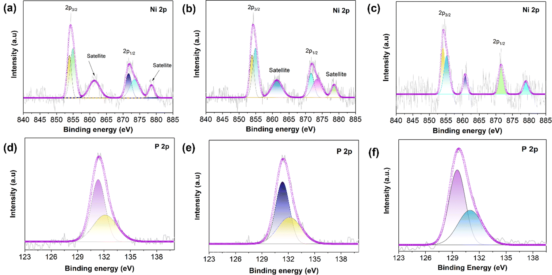 | ||
| Fig. 3 High-resolution deconvoluted XPS spectra of Ni 2p of (a) pristine NiP, (b) NiP@MIL-96 and (c) NiP@MIL-100. High-resolution deconvoluted XPS spectra of P 2p of (d) pristine NiP, (e) NiP@MIL-96 and (f) NiP@MIL-100. | ||
In the case of NiP@MIL-96, the representative peaks of nickel (Niδ+) and phosphorus species (Pδ−) revealed the formation of a NiP layer over the MIL-96 surface. Since the peaks of Ni 2p and P 2p were located exactly at the same positions as those of pristine NiP, it implies that MIL-96 had no influence on the NiP-coating, i.e., there was no chemical interaction between NiP and the substrate (MIL-96) (Fig. 3(b) and (e)). With regard to NiP@MIL-100 (Fig. 3(c)), it was found that the Ni 2p signals were positively shifted in contrast to that of pristine NiP. It should be mentioned that the high-valent Ni sites are conducive to the oxygen evolution activity because these species tend to be translated into OER active species (NiIIIOOH) more conveniently.41–43 On the other hand, P 2p peaks underwent a negative shift (Fig. 3(f)), which is attributed to the electronic modulation as an outcome of a higher electron density and the formation of metal–P bonds.44 Fig. S4(d) (ESI†) illustrates the high-resolution Fe 2p spectra of MIL-100, which comprises two main peaks, Fe 2p1/2 and Fe 2p3/2, and satellite shake-up peaks. In the case of the Fe 2p spectrum of NiP@MIL-100 samples (Fig. S4e, ESI†), the peak positioned at 708.6 eV may be ascribed to the Fe bonded to P, while the rest of the peaks may be assigned to the species of iron oxide.45 These results suggest that there was a strong interaction of the iron nodes in MIL-100 with P in the surface coated NiP layer. Such an interaction would obviously have an impact on the catalytic activity of the OER.
Electrochemical characterization of the various catalysts
The electrocatalytic activities of NiP, NIP@MIL-96 and NIP@MIL-100 for the OER were comparatively studied through linear sweep voltammetry (LSV). Fig. 4(a) illustrates the current density vs. polarization curves after the iR-correction. Notably, NiP itself displayed an appreciable OER performance, delivering a current density of 10 mA cm−2 at a low potential of 1.56 V against the reversible hydrogen electrode (RHE). The loading amount of NiP was optimized to achieve the best OER activity (Fig. S5, ESI†). The good OER performance of NiP may be attributed to the formation of amorphous NiOOH species on the catalyst surface, which corresponds to the pre-oxidation peak at 1.39 V vs. RHE. It is reported that the oxidation peak in the case of NiP-based catalysts indicates the oxidation of Ni2+ to Ni3+ as described by eqn (5) and (6).46,47 This amorphous layer protects against further oxidation and is favourable for the adsorption of reaction intermediates.| Ni2+ + 2OH− → Ni(OH)2 | (5) |
| Ni(OH)2 + OH− → NiOOH + e− + H2O | (6) |
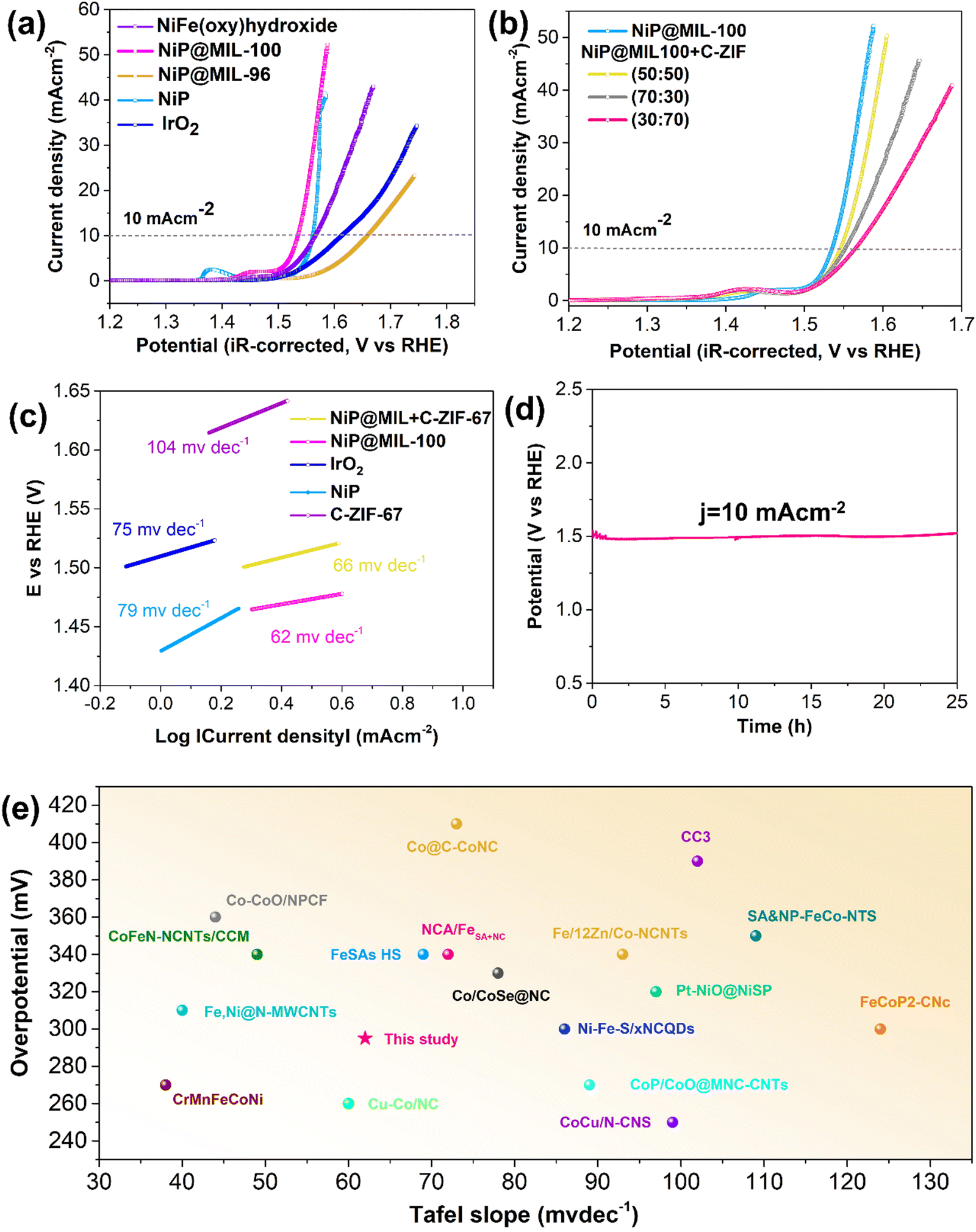 | ||
| Fig. 4 iR-corrected LSV curves of the OER of (a) NiP, NiP@MIL-100, NiP@MIL-96, NiFe(oxy)hydroxide and IrO2 catalysts in O2-saturated 0.10 M KOH solution at 1600 rpm, (b) iR-corrected LSV curves of the OER of NiP@MIL-100 and different ratios of NiP@MIL-100 + C-ZIF-67 (30:70, 50:50 and 70:30); (c) the corresponding Tafel slopes; (d) chronopotentiometry test of NiP@MIL-100 under a static current density of 10 mA cm−2 for 25 h; the total catalyst loading for each experiment: 0.255 mg cm−2; in the case of C-ZIF-67, there was no addition of super P, whereas super P was added into NiP@MIL-100 in the ratio of 5:3; and (e) comparison of overpotential vs. Tafel slope of recent studies. | ||
Remarkably, the OER performance was significantly enhanced upon coating NiP over the MIL-100 crystals as compared to the pristine NiP sample. The increased surface area and the presence of iron species may be credited to such improvement. The NiP@MIL-100 sample demonstrated the smallest overpotential (295 mV) to reach a current density of 10 mA cm−2, much superior to those of precious metal-based catalysts (e.g. IrO2). It should be mentioned that MIL-100 by itself showed rather poor OER performance (Fig. S6, ESI†). This suggests that such outstanding performance should be related to the strong interaction between the NiP coated layer and the substrate (MIL-100). The enhanced OER kinetics was also reflected by the reduced Tafel slope of NiP@MIL-100 (Fig. 4(c)). Interestingly, the pre-oxidation peak positively shifted to 1.47 V vs. RHE, corresponding to the transition of Ni3+ to Ni4+, which was recognized as the more redox active species for the OER.26 Thus, the presence of iron in MIL-100 likely suppressed the Ni2+/Ni3+ redox process and led to the Ni3+/Ni4+ active species.47 We also synthesized NiFe-LDH for the purpose of comparison, and it can be observed that NiP@MIL-100 still demonstrated superior OER activity to that of NiFe-LDH. On the other hand, the OER activity of NiP-plated MIL-96 dropped, which further confirms the importance of Fe species in MIL-100 and their interaction with NiP for enhancing the OER catalytic activity.
It is worth mention that NiP is unstable under OER conditions. During OER catalysis, an in situ reconstruction of the outermost NiP layer via electrochemical oxidation/dephosphorization would take place which modulated the coordination mode of Ni ions and eventually expedited the OER kinetics.46,48–51 To reveal the in situ reconstruction of nickel phosphides for OER active NiOOH active sites, XPS and TEM were conducted after the OER test of the NiP@MIL-100 catalyst. Of note, in the XPS spectra, the low-valent Ni (853.0 eV) peaks, attributed to Ni–P in the as-synthesized sample, disappeared after the OER performance test and the peak corresponding to NiOOH became prominent (Fig. S7, ESI†). Furthermore, the P signal attenuated and is actually beyond the detection limit of XPS (Fig. S8, ESI†). Similarly, TEM micrographs of post-OER activity also displayed the formation of NiOOH (Fig. S9, ESI†). Notably, phosphorus deficient surface layers can also be visualized by HAADF-STEM. Thus, these results imply that surface-bound nickel phosphides were oxidized to oxyhydroxides, which is in line with the recent findings.39,52
In NiP@MIL-100, although the MOF by itself has poor OER activity, it considerably contributed indirectly to reducing the OER overpotential because of the presence of Fe3+ species which interacted with the re-constructed NiP to modify the electronic structure of the active components. Actually, in the presence of NiOOH, Fe3+ is oxidized to Fe4+, leading to high OER activity and the lowest overpotential. To decipher the excellent activity, Xiao et al. conducted a theoretical study and established a convincing reasoning about the outstanding synergy between Fe and Ni species: low spin d6 Ni4+ ions trigger the O–O bond formation whereas high spin d4 Fe4+ ions boost the stability of oxyl radicals.53 This undoubtedly explains that the rise in OER activity is the interplay between Ni in the coating layer and Fe sites from the substrate in this study, leading to the lowest overpotential. Besides, MIL-100 also served as a three-dimensional framework support to expose maximal active sites and to ensure efficient charge/mass transfer. The OER stability of NiP@MIL-100 was determined through the chronopotentiometry test under a static current density of 10 mA cm−2 over a period of 25 h. The chronopotentiometry test displayed no discernible change in the overpotential, implying high catalytic durability of NiP@MIL-100 for the OER in an alkaline solution (Fig. 4(d)). A comparison with the latest OER catalysts shows the superior performance of NiP@MIL-100 (Fig. 4(e) and Table S3, ESI†).
The ORR activity of NiP@MIL-100 was then also evaluated by the half-wave potential (E1/2). Despite its outstanding OER performance, NiP@MIL-100 demonstrated just modest ORR performance (Fig. 5(a)). This can be easily understood – different active sites are required for both reactions, while it is difficult to realize high performance with a single catalyst. As is known, MOF-derived materials (for example, by carbonization treatment) could potentially contribute to the ORR activity. Therefore, NiP@MIL-100 was pyrolyzed at 750 °C under an N2 atmosphere. Surprisingly, the electrocatalytic performance in the case of NiP@MIL-100 samples was exacerbated followed by calcination (Fig. S10, ESI†). It implies that calcination had an adverse effect on the NiP plated samples and eventually on the catalytic performance. Actually, when NiP@MIL-100 was subjected to the heating treatment, the NiP coating started to decompose, with the release of phosphorus as a result of evaporation.54 At this high temperature (750 °C), inter-diffusion between NiP and the MIL-100 substrate took place, leading to the formation of the NiFe alloy accompanied by the release of phosphorus.55,56 The ORR mechanism of the carbonized sample was also investigated by employing rotating ring-disk electrode (RRDE) measurements, as shown in Fig. S11 (ESI†), from which the number of electrons transferred and the peroxide (HO2−) yield were determined. The electron transfer number and peroxide (HO2−) yield also give an indication of the selectivity of the catalyst towards the ORR activity. Generally, ORR catalysis is governed by either the 2e− pathway or the 4e− pathway. Actually, the 4e− pathway is considered more conducive towards ORR catalysis, given the fact that it promotes the complete reduction of oxygen molecules to OH− ions with no or minimum peroxide (HO2−) yield. Interestingly, it was observed that the number of electrons transferred for the carbonized-NiP@MIL-100 sample was about 3.9 and the amount of peroxide (HO2−) yield was negligible over the whole potential range, comparable to the ORR benchmark catalyst (Pt/C). This implies that the reaction pathway for the carbonized NiP@MIL-100 was dominated by a quasi-four electron process. This may be attributed to the NiFe alloy formation, which significantly contributed to achieving the 4e− pathway. It implies that the carbonized sample was efficient in breaking the O–O bond, and in response, it also produced negligible peroxide (HO2−) yield. On the other hand, the pristine NiP@MIL-100 sample underwent approximately 2e− pathway. Thus, it can be concluded that despite inferior ORR activity, the carbonized NiP@MIL-100 sample demonstrated excellent selectivity toward the ORR.
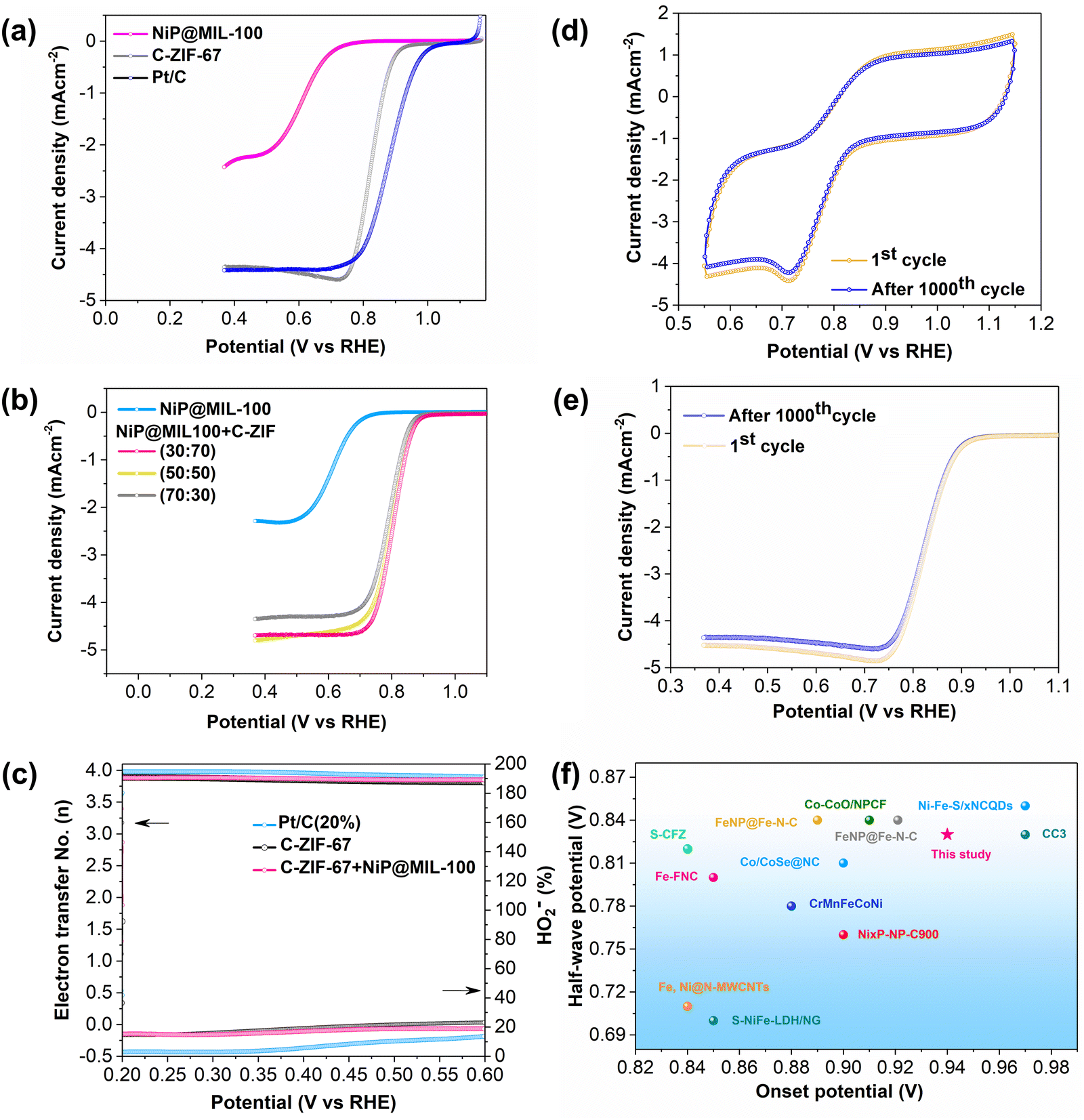 | ||
| Fig. 5 (a) LSV curves of ORR of NiP, NiP@MIL-100 catalysts in O2-saturated 0.10 M KOH solution at 1600 rpm; (b) LSV curves of ORR of NiP@MIL-100 and different ratios of NiP@MIL-100 + C-ZIF-67 (30:70, 50:50 and 70:30); (c) electron transfer number and percentage of HO2− of carbonized MIL-100, carbonized ZIF-67 and Pt/C (20%); (d) accelerated cyclic voltammograms (CV) at a scan rate of 100 mV s−1; (e) LSV curves before and after 1000 CV cycles; the total catalyst loading for each experiment: 0.255 mg cm−2; and (f) the comparison of the half-wave potential vs. the onset potential of recent studies. | ||
The ORR activity of C-ZIF-67 was also evaluated, and it is worth mentioning that C-ZIF-67 demonstrated excellent ORR activity with a much more positive E1/2 value (Fig. 5(a)), high ORR selectivity with a quasi-four electron transfer pathway and a low peroxide yield (Fig. 5(c)). A comparison of the ORR activity of C-ZIF-67 was made with the latest ORR active catalysts, and it showed a superior performance to those of other catalysts (Fig. 5(f) and Table S3, ESI†). To achieve the best bi-functional activity for both ORR and OER activities, the mass ratio of NiP@MIL-100 and C-ZIF-67 was optimized and 50:50 was found to be the optimal ratio (Fig. 4b and 5b).
The ORR stability of C-ZIF-67 was also appraised by employing the accelerated cyclic voltammetry for 1000 cycles (Fig. 5(d) and (e)). It is worth mentioning that there was an insignificant decline in the ORR activity over 1000 CV cycles, indicating the excellent ORR stability of the C-ZIF-67 catalyst. Subsequently, the bi-functional activity of NiP@MIL-100 and C-ZIF-67 was also appraised at different ratios by the bi-functional activity parameter (potential gap), ΔE = Ej=10 − E1/2, defined as the difference in the potential at a current density of j = 10 mA cm−2 (OER) and half-wave potential (ORR) as shown in Fig. S12 (ESI†). ΔE was found to be only 0.73 V for the optimal NiP@MIL-100 + C-ZIF-67 (50:50) composite, which makes it an excellent bi-functional air electrode for ZABs (Fig. 6(a)).
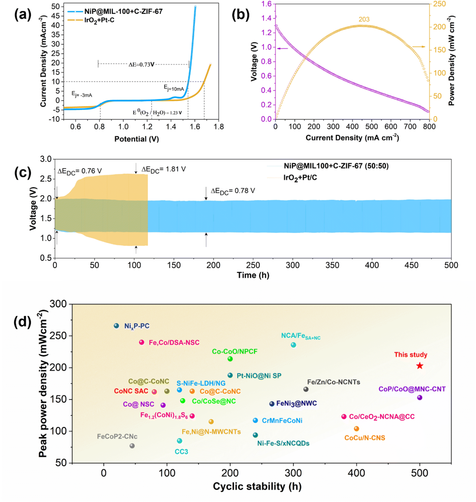 | ||
| Fig. 6 (a) Overall polarization curves of C-ZIF-67 + NiP@MIL-100 and commercial Pt/C + IrO2 in 0.1 M KOH; (b) power density and discharge curves of C-ZIF-67 + NiP@MIL-100; (c) galvanostatic charge/discharge test for rechargeable zinc–air battery based on pristine NiP@MIL-100 + carbonized ZIF-67 (total catalyst loading: 1 mg cm−2) and IrO2/Pt (total catalyst loading: 1 mg cm−2) catalysts tested for cyclic stability at 5 mA cm−2; and (d) comparison of peak power density vs. cyclic stability of zinc–air batteries of recent studies. | ||
Zn–air battery testing of catalysts
Given the outstanding OER/ORR performance of NiP@MIL-100 + C-ZIF-67 (50:50), we further integrated this composite catalyst into a ZAB to determine the battery performance and cycling stability to assess its feasibility as an air electrode for practical cells (Fig. 6(c)). Notably, the corresponding ZAB displayed a high peak power density of 203 mW cm−2 (Fig. 6(b) and Fig. S13, ESI†). Interestingly, the NiP@MIL-100 + C-ZIF-67 (50:50) assembled ZAB demonstrated a remarkable performance with a smaller discharge and charge voltage gap (ΔEDC) of 0.78 V as well as a robust discharge/charge cycling over a period of 500 h. In contrast, the ZAB assembled with a precious metal-based IrO2–Pt/C catalyst started to decline even after a few hours. A comparison with the latest reported air electrodes shows that the optimal catalyst displayed superior performance (Fig. 6(d) and Table S3, ESI†). Excellent performance of the optimal catalyst for ZABs was also demonstrated at some higher current densities (10, 15 and 20 mA cm−2) with a lower voltage gap (Fig. S14, ESI†).
For comparison, pristine NiP@MIL-100, carbonized NiP@MIL-100 and a mixture of pristine and carbonized NiP@MIL-100 (50:50 by mass) samples were also integrated into ZABs as air electrodes. It was found that the pyrolysis of NiP-coated MIL-100 is counterproductive due to the decomposition of the NiP coating (Fig. S15–S17, ESI†). Consequently, NiP-plated on pristine MIL-100 and coupled with carbonized ZIF-67 may be employed as a bifunctional oxygen electrocatalyst for rechargeable ZABs, wherein NiP plated on pristine MIL-100 contributed to the OER and C-ZIF-67 served as the ORR catalyst (Fig. 7).
 | ||
| Fig. 7 Possible mechanism of NiP-plated MIL-100 and C-ZIF-67. | ||
Conclusions
In summary, we designed a bi-functional (OER/ORR) and efficient air electrode using the dual-MOF strategy for ZABs wherein one MOF acts as a support to expose OER active sites and the other MOF acts as a precursor for producing carbonized samples as ORR catalysts and enhances the electronic conductivity. NiP electroless plating, a facile strategy to provide uniform NiP dispersion over the pristine MOF substrates, i.e. MIL-100 and MIL-96, was utilized to successfully synthesize the NiP plated materials. Fe containing MOF substrates such as MIL-100 were found to be optimal substrates. On one hand, MIL-100 served as a 3D scaffold to expose maximum NiP active sites and on the other hand, uniformly distributed metal (Fe) nodes over the surface of the MOF triggered the active sites to more redox active Ni sites, boosting the OER activity. As a consequence, NiP@MIL-100 delivered a current density of 10 mA cm−2 with an overpotential of 295 mV and a low Tafel slope of 62 mV dec−1. Eventually, the pristine NiP@MIL-100 catalyst was coupled with carbonized ZIF-67, an excellent ORR catalyst. Consequently, the dual MOFs considerably compensated for each other's deficiencies and culminated in an excellent bi-functional (OER/ORR) air cathode. The resultant catalyst exhibited excellent activity and stable charge/discharge cycling performance for zinc–air batteries over a period of 500 h with a high peak power density of 203 mW cm−2. The development of NiP-plated catalysts is a facile and scalable strategy, and it does not involve some specialized equipment; therefore, this strategy may be implemented to a commercial scale.Conflicts of interest
There are no conflicts to declare.Acknowledgements
This work was supported by the Australian Research Council Discovery Projects (grant no. DP200103315, DP200103332, DP220103669 and DP230100685) and the Linkage Projects (grant no. LP220200920). Y. Arafat would also like to acknowledge the support provided by the “Australian Government Research Training Program (RTP) Scholarship” at Curtin University, Perth, Australia.References
- A. S. Al-Fatesh, Y. Arafat, S. O. Kasim, A. A. Ibrahim, A. E. Abasaeed and A. H. Fakeeha, Appl. Catal., B, 2021, 280, 119445 CrossRef CAS.
- Y. Zhong, X. Xu, W. Wang and Z. Shao, Batteries Supercaps, 2019, 2, 272–289 CrossRef CAS.
- C.-X. Zhao, J.-N. Liu, B.-Q. Li, D. Ren, X. Chen, J. Yu and Q. Zhang, Adv. Funct. Mater., 2020, 30, 2003619 CrossRef CAS.
- Y. Arafat, Y. Zhong, M. R. Azhar, M. Asif, M. O. Tadé and Z. Shao, EcoMat, 2023, 5, e12394 CrossRef CAS.
- L. Wang, Q. Zhou, Z. Pu, Q. Zhang, X. Mu, H. Jing, S. Liu, C. Chen and S. Mu, Nano Energy, 2018, 53, 270–276 CrossRef CAS.
- I. Mondal, H. Lee, H. Kim and J. Y. Park, Adv. Funct. Mater., 2020, 30, 1908239 CrossRef CAS.
- M. Saruyama, S. Kim, T. Nishino, M. Sakamoto, M. Haruta, H. Kurata, S. Akiyama, T. Yamada, K. Domen and T. Teranishi, Chem. Sci., 2018, 9, 4830–4836 RSC.
- J. Zhang, K. Hou, Q. Yao, C. Wu, M. Huang and L. Guan, Int. J. Hydrogen Energy, 2019, 44, 11684–11694 CrossRef CAS.
- S. Sankar, Y. Sugawara, S. Assa Aravindh, R. Jose, T. Tamaki, G. M. Anilkumar and T. Yamaguchi, ACS Appl. Energy Mater., 2020, 3, 879–888 CrossRef CAS.
- A. Meena, P. Thangavel, D. S. Jeong, A. N. Singh, A. Jana, H. Im, D. A. Nguyen and K. S. Kim, Appl. Catal., B, 2022, 306, 121127 CrossRef CAS.
- M. Gao, Z. Wang, S. Sun, D. Jiang and M. Chen, Nanotechnology, 2021, 32, 195704 CrossRef CAS PubMed.
- X. Li, W.-Q. Huang, L.-X. Xia, Y.-Y. Li, H.-W. Zhang, S.-F. Ma, Y.-M. Wang, X.-J. Wang and G.-F. Huang, ChemElectroChem, 2020, 7, 4047–4054 CrossRef CAS.
- C. Zhang, X. Du and X. Zhang, Int. J. Hydrogen Energy, 2022, 47, 10825–10836 CrossRef CAS.
- L.-A. Stern, L. Feng, F. Song and X. Hu, Energy Environ. Sci., 2015, 8, 2347–2351 RSC.
- J. Xu, J. P. S. Sousa, N. E. Mordvinova, J. D. Costa, D. Y. Petrovykh, K. Kovnir, O. I. Lebedev and Y. V. Kolen’ko, ACS Catal., 2018, 8, 2595–2600 CrossRef CAS.
- M. Miao, R. Hou, R. Qi, Y. Yan, L. Q. Gong, K. Qi, H. Liu and B. Y. Xia, J. Mater. Chem. A, 2019, 7, 18925–18931 RSC.
- J. Xu, X.-K. Wei, J. D. Costa, J. L. Lado, B. Owens-Baird, L. P. Gonçalves, S. P. Fernandes, M. Heggen, D. Y. Petrovykh and R. E. Dunin-Borkowski, ACS Catal., 2017, 7, 5450–5455 CrossRef CAS.
- L.-M. Cao, J. Zhang, L.-W. Ding, Z.-Y. Du and C.-T. He, J. Energy Chem., 2022, 68, 494–520 CrossRef CAS.
- W. Li, C. Wang and X. Lu, J. Mater. Chem. A, 2021, 9, 3786–3827 RSC.
- Y. Huang, X. Song, J. Deng, C. Zha, W. Huang, Y. Wu and Y. Li, Appl. Catal., B, 2019, 245, 656–661 CrossRef CAS.
- P. Li, R. Chen, S. Tian and Y. Xiong, ACS Sustainable Chem. Eng., 2019, 7, 9566–9573 CrossRef CAS.
- Y. Wang, J. Liu, T. Lu, R. He, N. Xu and J. Qiao, Appl. Catal., B, 2023, 321, 122041 CrossRef CAS.
- R. He, T. Lu, N. Xu, G. Liu, Y. Zhang and J. Qiao, Chem. Eng. J., 2023, 461, 141843 CrossRef CAS.
- C.-C. Hou, L. Zou, Y. Wang and Q. Xu, Angew. Chem., Int. Ed., 2020, 59, 21360–21366 CrossRef CAS PubMed.
- S. Anantharaj, S. Kundu and S. Noda, Nano Energy, 2021, 80, 105514 CrossRef CAS.
- L. Trotochaud, S. L. Young, J. K. Ranney and S. W. Boettcher, J. Am. Chem. Soc., 2014, 136, 6744–6753 CrossRef CAS PubMed.
- A. Sivanantham, P. Ganesan and S. Shanmugam, Adv. Funct. Mater., 2016, 26, 4661–4672 CrossRef CAS.
- Y. Zhong, X. Xu, P. Liu, R. Ran, S. P. Jiang, H. Wu and Z. Shao, Adv. Energy Mater., 2020, 10, 2002992 CrossRef CAS.
- W. Zhang, Y. Zou, H. Liu, S. Chen, X. Wang, H. Zhang, X. She and D. Yang, Nano Energy, 2019, 56, 813–822 CrossRef CAS.
- B. Hui, J. Li, Y. Lu, K. Zhang, H. Chen, D. Yang, L. Cai and Z. Huang, J. Energy Chem., 2021, 56, 23–33 CrossRef CAS.
- Y. Arafat, M. R. Azhar, Y. Zhong, M. O. Tadé and Z. Shao, Mater. Res. Bull., 2021, 140, 111315 CrossRef CAS.
- Y. Zhong, X. Xu, W. Wang and Z. Shao, Batteries Supercaps, 2019, 2, 272–289 CrossRef CAS.
- Y. Arafat, M. R. Azhar, Y. Zhong, H. R. Abid, M. O. Tadé and Z. Shao, Adv. Energy Mater., 2021, 11, 2100514 CrossRef CAS.
- M. R. Azhar, H. R. Abid, M. O. Tade, V. Periasamy, H. Sun and S. Wang, Chem. Eng. J., 2018, 341, 262–271 CrossRef CAS.
- M. Al Haydar, H. R. Abid, B. Sunderland and S. Wang, Drug Des., Dev. Ther., 2019, 13, 23 CrossRef CAS PubMed.
- Y. Arafat, M. R. Azhar, Y. Zhong, X. Xu, M. O. Tadé and Z. Shao, Nano-Micro Lett., 2020, 12, 1–16 CrossRef PubMed.
- F. Razmjooei, C. Pak and J.-S. Yu, ChemElectroChem, 2018, 5, 1985–1994 CrossRef CAS.
- B. Z. Desalegn, H. S. Jadhav and J. G. Seo, Sustainable Energy Fuels, 2020, 4, 1863–1874 RSC.
- M. R. Azhar, Y. Arafat, M. Khiadani, S. Wang and Z. Shao, Composites, Part B, 2020, 192, 107985 CrossRef CAS.
- J. Xu, J. P. Sousa, N. E. Mordvinova, J. D. Costa, D. Y. Petrovykh, K. Kovnir, O. I. Lebedev and Y. V. Kolen’ko, ACS Catal., 2018, 8, 2595–2600 CrossRef CAS.
- H. Roh, H. Jung, H. Choi, J. W. Han, T. Park, S. Kim and K. Yong, Appl. Catal., B, 2021, 297, 120434 CrossRef CAS.
- S. Zhao, C. Tan, C.-T. He, P. An, F. Xie, S. Jiang, Y. Zhu, K.-H. Wu, B. Zhang and H. Li, Nat. Energy, 2020, 5, 881–890 CrossRef CAS.
- J. Zhang, H. Yu, J. Yang, X. Zhu, M. Hu and J. Yang, J. Alloys Compd., 2022, 924, 166613 CrossRef CAS.
- X. Zhang, L. Zhang, G.-G. Zhu, Y.-X. Zhu and S.-Y. Lu, ACS Appl. Mater. Interfaces, 2020, 12, 7153–7161 CrossRef CAS PubMed.
- K. Liu, F. Wang, P. He, T. A. Shifa, Z. Wang, Z. Cheng, X. Zhan and J. He, Adv. Energy Mater., 2018, 8, 1703290 CrossRef.
- L.-A. Stern, L. Feng, F. Song and X. Hu, Energy Environ. Sci., 2015, 8, 2347–2351 RSC.
- A. Dutta, S. Mutyala, A. K. Samantara, S. Bera, B. K. Jena and N. Pradhan, ACS Energy Lett., 2017, 3, 141–148 CrossRef.
- X. Wang, W. Li, D. Xiong and L. Liu, J. Mater. Chem. A, 2016, 4, 5639–5646 RSC.
- X.-Y. Yu, Y. Feng, B. Guan, X. W. D. Lou and U. Paik, Energy Environ. Sci., 2016, 9, 1246–1250 RSC.
- D. Huo, F. Song, J. Hu, J. Yuan, L. Niu and A.-J. Wang, Int. J. Hydrogen Energy, 2021, 46, 8519–8530 CrossRef CAS.
- Z. Fang, L. Peng, Y. Qian, X. Zhang, Y. Xie, J. J. Cha and G. Yu, J. Am. Chem. Soc., 2018, 140, 5241–5247 CrossRef CAS PubMed.
- H. Liang, A. N. Gandi, D. H. Anjum, X. Wang, U. Schwingenschlögl and H. N. Alshareef, Nano Lett., 2016, 16, 7718–7725 CrossRef CAS PubMed.
- H. Xiao, H. Shin and W. A. Goddard, Proc. Natl. Acad. Sci., 2018, 115, 5872–5877 CrossRef CAS PubMed.
- S. Eraslan and M. Ürgen, Surf. Coat. Technol., 2015, 265, 46–52 CrossRef CAS.
- P. H. Lo, W. T. Tsai, J. T. Lee and M. P. Hung, Scr. Metall. Mater., 1993, 29, 37–42 CrossRef CAS.
- K. L. Lin and P. J. Lai, J. Electrochem. Soc., 1990, 137, 1509 CrossRef CAS.
Footnote |
| † Electronic supplementary information (ESI) available. See DOI: https://doi.org/10.1039/d4ey00008k |
| This journal is © The Royal Society of Chemistry 2024 |