
 Open Access Article
 This Open Access Article is licensed under a Creative Commons Attribution-Non Commercial 3.0 Unported Licence
Enhanced H2 production at the atomic Ni–Ce interface following methanol steam reforming†
Yaqi
Hu‡
a,
Zhong
Liang‡
a,
Yabin
Zhang
b,
Yaping
Du
 *acd and
Hongbo
Zhang
*ac
*acd and
Hongbo
Zhang
*ac
aTianjin Key Lab for Rare Earth Materials and Applications, Center for Rare Earth and Inorganic Functional Materials, Smart Sensing Interdisciplinary Science Center, School of Materials Science and Engineering, National Institute for Advanced Materials, Nankai University, Tianjin, 300350, P. R. China. E-mail: ypdu@nankai.edu.cn; hbzhang@nankai.edu.cn
bState Key Laboratory of Featured Metal Materials and Life-cycle Safety for Composite Structures, MOE Key Laboratory of New Processing Technology for Nonferrous Metals and Materials, and School of Resources Environment and Materials, Guangxi University, Nanning, 530004, P. R. China
cHaihe Laboratory of Sustainable Chemical Transformations, Tianjin, 300350, P. R. China
dKey Laboratory of Rare Earths, Chinese Academy of Sciences, Ganzhou, 341119, P. R. China
First published on 10th November 2023
Abstract
Hydrogen production with high efficiency and low CO selectivity in methanol steam reforming (MSR) is of pivotal importance. However, there is limited understanding of the active sites and reaction mechanisms during catalysis. In this study, we maximized the interfacial site, known as the active component in MSR, of Ni–CeOx by atomically dispersed Ni and Ce over the carbon–nitrogen support to generate the Ni and Ce dual-atomic catalyst (DAC), which achieved 6.5 μmolH2 gcat.−1 s−1 H2 generation rate and 0.8% CO selectivity at 99.1% methanol conversion at 513 K. The finely dispersed Ni and Ce structure was confirmed by systematic characterization of AC HAADF-STEM and EXAFS. Electron transfer from Ce to Ni was confirmed simultaneously by quasi-in situ XPS analysis. Moreover, the reaction mechanism of methanol steam reforming was clarified by combining kinetic studies with isotope-tracing/exchange analysis (i.e., KIEs and steady-state isotopic transient kinetic analysis (SSITKA)), which suggests that the steam reforming consists of two tandem reaction processes: methanol decomposition (MD) and water–gas shift (WGS) reaction, with methanol and water activation at independent active sites (e.g., Ni and oxygen vacancy over CeOx), and that hydrogen generation was primarily determined by both C–H bond rupture and OL–H (OL represents the lattice oxygen) cleavage within methoxy and hydroxyl groups, respectively, with the catalytic surface mainly covered by CO and methoxy groups. A shift of WGS involvement in hydrogen generation from negligibly influenced to significantly promoted was selectively observed once modifying the reaction from differential conditions to a high methanol conversion regime, and two quantification methods have been established by comparing the molecule ratio between CO and CO2 or H2.
Broader contextHydrogen is regarded as a clean energy resource to solve the increasingly serious energy crisis and environmental pollution due to its high energy density and no greenhouse gas emissions during consumption. However, the safe transportation and storage has been an obstacle to its widespread application. Liquid fuel as a hydrogen carrier is a good solution. Methanol is a promising liquid organic hydrogen carrier (LOHC) with a wide range of sources, low price, high hydrogen content and low transportation temperature. Methanol steam reforming (MSR) has a high efficiency in hydrogen production and was widely applied in industry. Currently, the main catalytic systems used are Cu-based non-noble metal catalysts and Pt-based or Pd-based noble metal catalysts. Nevertheless, the poor stability and high price limit their wide application. We constructed an efficient and stable NiCe dual-atomic catalyst containing a large number of atomically dispersed Ni–CeOx interfacial sites, with high conversion and low CO selectivity in MSR, and confirmed the reaction mechanism of MSR within this catalytic system. Our work will inspire further explorations in the establishment of atomically NiCe active interfacial sites to enhance reaction activity. |
Introduction
Hydrogen is definitely a good energetic resource owing to its high energy content and negligible contamination of the environment. However, it was prohibited from widespread utilization owing to its unstable nature.1 People keep looking for alternative strategies to replace the traditional method in hydrogen generation, storage and transportation. For example, compared with the high temperature production from fossil fuels, in situ generated hydrogen from oxygenated chemicals, such as methanol is more attractive due to the low energy requirement during catalysis,2–5 which includes methanol steam reforming (MSR), methanol partial oxidation (MPO), methanol oxidative steam reforming (MOSR), and methanol aqueous-phase reforming (MAPR). MSR is the most efficient method with a high H2 gravimetric density of 18.8% and has been widely applied in industry.5–8However, the overall reaction performance of MSR has been influenced by the limited understanding of the reaction mechanism received. Nevertheless, several hypothesized reaction routes have been proposed, which include the dissociative adsorption of methanol followed by subsequent dehydrogenation, and the reaction intermediates vary along with different processes.9 For example, until now, three different reaction pathways have been proposed and suggest three different reaction intermediates, including CO*,10–14 CHOOCH3*15,16 and CHOO*,17–20 in which the formate-pathway is mostly accepted. In addition, Peppley12,13 and Iglesia14 both suggested that the MSR followed a tandem reaction process with methanol dehydrogenation (MD), followed by water–gas shift (WGS) reactions. Iglesia et al. proposed that the elementary step for the dehydrogenation of CH3O* is the rate-determining step (RDS) with the WGS reaction as quasi-equilibrated, which was supported by the isotopic and kinetic assessment applied. However, this adjustment might rely on the systems investigated and the reaction conditions applied. WGS will not always be facile with respect to MD or MSR.
With a systematic investigation, it was observed that the interface structure between transition metals and reducible metal oxides within the catalysts plays a vital role in regulating the reaction activity.11,18,21–26 For example, Li et al.18 developed a method to optimize the surface structure of the commercial Cu/ZnO/Al2O3 catalyst by manipulating the composition of reducing agents at the activation stage. Due to the existence of adsorbate-induced strong metal–support interactions, the ZnOx species would constantly migrate to the surface of the metallic Cu0 nanoparticles, forming abundant Cu–ZnOx interfacial sites. This resulted in the long-term stability, and the catalytic activity of MSR was significantly improved. More interestingly, Köwitsch et al.21 designed In3Pd2–InPd/In2O3 nanocomposites with significant amounts of interfaces formed. This was induced by the dynamic reactive metal–support interaction (RMSI) between the intermetallic In–Pd and In2O3 under the MSR reaction, leading to an unusually high CO2 selectivity of 99% at 573 K. Furthermore, they proposed the participation of oxygen from the reactive InxPdy/In2O3 interface by isotope-labeling. Our recent work also suggests that the interfacial sites are the active component for both WGS27 and MSR28 reactions. Therefore, it is crucial to maximize the interfacial sites that could be achieved by reducing the size of the metal nanoparticles to clusters or even single atoms,29 and improve the efficiency of metal utilization and control the related side reactions. Specifically, Ma et al. synthesized Au layered clusters,30 isolated Pt atoms (Pt1) and subnanometer Pt clusters (Ptn)31 decorated α-MoC catalysts to create the interfacial catalytic systems for the ultra-low-temperature WGS reaction, which is the primary side reaction of MSR. The abundant surface hydroxyls of α-MoC provide significant active sites for water dissociation. Owing to the excellent catalytic performance of α-MoC in WGS, they developed a series of good catalysts with atomically dispersed Pt11 or Ni,32 which exhibited extraordinary hydrogen production activity in the aqueous-phase methanol reforming. The synergy between Pt or Ni and α-MoC also produces an active interfacial structure for methanol reforming.
Additionally, as described in the literature, the most commonly utilized catalytic system can be classified into non-noble-metal catalysts such as Cu-based catalysts17,18,33–36 and noble-metal catalysts, for example, Pd-based36,37 or Pt-based catalysts.11,38,39 However, the biggest problem with the Cu-based catalysts is the tendency of Cu crystallization and readily sintering at relatively high temperature. As for noble-metal catalysts, although the activities are excellent, the high price is the main obstacle limiting their large-scale application. Therefore, developing efficient non-noble-metal catalytic systems with high reactivity and stability is highly desired but challenging.40–42
Collectively, people have devoted many efforts in improving the reactivity of alcohols (methanol and ethanol) steam reforming by: (i) establishing active transition metal–metal oxide interface;17,18,21,43–48 (ii) constructing active bimetallic-mineral support structure, etc.49–51 Rare earth oxides such as cerium oxide (CeO2) have been confirmed to play an important role in our previous work27,52 due to the rich oxygen vacancy (OV) and unique electronic structures. Therefore, the atomically dispersed CeOx would help water activation during catalysis. Here, we designed an atomically dispersed Ni–CeOx interfacial catalyst by the stepwise selective decoration of isolated Ni and Ce to the carbon–nitrogen support, which would certainly help to establish an atomically bonded interfacial structure (i.e., Ni–CeOx DAC).53 During the catalytic evaluation, this specific active site does facilitate the MSR to some extent. The enhanced overall dehydrogenation rate was determined at 6.5 μmolH2 gcat.−1 s−1 at 513 K with limited CO generated (∼0.8%) at 99.1% methanol conversion. With this simple reaction model established, the overall reaction mechanism of MSR was tentatively probed by a combination of kinetic studies, isotope-tracing experiments, as well as steady-state isotopic transient kinetic analysis (SSITKA), in which hydrogen formation was proved to be determined by a combination of C–H bond rupture within CH3O* and OL–H (OL: lattice oxygen) bond cleavage (kinetically relevant) during MSR, respectively.
Results and discussion
Synthesis and structural characterization of the NiCe/CN DAC
To synthesize the Ni and Ce dual-atomic catalyst (NiCe/CN DAC), atomic Ni and Ce centers were deposited to the carbon nitride (CN) support following an incipient wetness impregnation method (detailed preparation procedures presented in Experimental section). Powder X-ray diffraction (XRD) was employed to investigate the structure of the as-prepared dual and single atom catalysts. XRD patterns (Fig. S1, ESI†) show only one peak corresponding to nitrogen-doped carbon and no diffraction peaks attributed to metal in all catalysts. The morphology of the fresh NiCe/CN DAC was investigated by the transmission electron microscope (TEM). Fig. 1a(i) and Fig. S2(i) (ESI†) show the morphology of the thin rolled nanosheets. As determined by the Brunauer–Emmett–Teller (BET) method, the specific surface area of NiCe/CN DAC was 43.1 m2 g−1 (Fig. S3a, ESI†). Pores with an average size of ∼6.9 nm were also revealed from the gas adsorption isotherms (Fig. S3b, ESI†). Similar to NiCe/CN DAC, the specific surface area of Ni/CN SAC was 46.9 m2 g−1 and the pores of Ni/CN SAC had an average size of ∼6.8 nm (Fig. S3c and d, ESI†), suggesting that the addition of different metals has little effect on the morphology and pore structure of the support. In addition, Ni/CeO2 prepared by the incipient wetness impregnation method has a significantly different pore structure, with a specific surface area of 65.5 m2 g−1 and pores with an average diameter of ∼11.1 nm (Fig. S3e and f, ESI†). | ||
| Fig. 1 Characterizations of the fresh NiCe/CN DAC. (a, i) TEM image, (a, ii-vi) elemental mappings and (b) AC HAADF-STEM image of NiCe/CN DAC-fresh; (c) FT-EXAFS spectra and (d) wavelet transform analysis for the Ni K-edge of (i) NiCe/CN DAC and (ii) Ni foil; (e) FT-EXAFS spectra and (f) wavelet transform analysis for the Ce K-edge of (i) NiCe/CN DAC and (ii) CeO2. | ||
The elemental distribution of the NiCe/CN DAC was ascertained by the energy-dispersive spectroscopy (EDS) mapping. Fig. 1a(ii, iii) and Fig. S2(iii, iv) (ESI†) show that the signals of the Ni and Ce elements are uniformly distributed throughout the CN support, confirming the high dispersion of Ni and Ce centers within NiCe/CN DAC. To further confirm that, Aberration-corrected high-angle annular dark field-scanning transmission electron microscopy (AC HAADF-STEM) was conducted. The isolated bright spots can be distinguishably identified, corresponding to monodispersed Ni and Ce centers with an average diameter of 0.27 nm (Fig. 1b, eqn (5)). X-ray absorption spectroscopy (XAS) was also performed to further reveal the valence states and the coordination environments of the metal atom centers, in which the Fourier-transformed extended X-ray absorption fine structure (FT-EXAFS) analysis and wavelet transform (WT) analysis provide an intuitive way of further ascertaining the dispersion state of metal atoms in the NiCe/CN DAC through the comparison with reference samples. As shown in Fig. 1c, the Fourier transformed k3-weighted χ(k)-function of the EXAFS spectrum for NiCe/CN DAC shows only one characteristic peak at around 1.49 Å. This peak can be assigned to the Ni–N(O) scattering of the atomic Ni coordinated with N(O), which distinguishes from the peak corresponding to metallic Ni–Ni scattering at ∼2.16 Å in Ni foil.32 The WT of the EXAFS spectrum for the Ni K-edge of NiCe/CN DAC shows the characteristic peak of the Ni–N(O) bond at 3.35 Å that can be assigned to the atomic Ni–N(O) species (Fig. 1d(i)). The WT of the EXAFS spectrum for the Ni K-edge of Ni foil shows the Ni–Ni bond at 7.4 Å−1 that can be attributed to Ni particles (Fig. 1d(ii)). Meanwhile, two distinct peaks appear at 1.75 Å and 3.52 Å in the EXAFS spectrum of the Ce K-edge of the CeO2 sample (Fig. 1e). The former is due to the Ce–O scattering and the latter is attributed to the Ce–Ce scattering, respectively. NiCe/CN DAC shows only one peak derived from Ce–N(O) scattering at about 1.93 Å. As shown in Fig. 1f(i), the WT of the EXAFS spectrum on the Ce K-edge of NiCe/CN DAC shows the characteristic peak of the Ce–N(O) bond at 3.93 Å−1, while CeO2 shows the characteristic peak of the Ce–O bond at 4.73 Å−1 (Fig. 1f(ii)), which further confirms the co-existence of isolated Ni and Ce sites, consistent with the above HADDF-STEM results. According to the EXAFS fitting parameters in Table S1 (ESI†), each isolated Ni and Ce atom is coordinated by N atoms and (or) O atoms (note that it is difficult to discern N and O coordinates by EXAFS fitting due to their similar atomic numbers).54 The Ni–N(O) shows a coordination number of 5.8 at a distance of 2.04 Å, while Ce–N(O) shows a higher coordination number of 12.1 at a distance of 2.59 Å. Considering the strong affinity with the oxygen of Ce, it is easy to absorb O2 from the atmosphere and then form the structure with high coordination number.55 Combined with the detailed information of the metal loadings determined by inductively coupled plasma atomic emission spectroscopy (ICP-AES, Table S2, ESI†), atomically dispersed NiCe/CN DAC could be obtained even though the metal loadings increased to 2.2 wt% and 4.9 wt% for Ni and Ce elements, respectively. The TEM characterizations were also performed on the sample of the spent NiCe/CN DAC, in which the image (Fig. S4a, ESI†) shows that the atoms were slightly agglomerated after the reaction. The elemental mappings (Fig. S4d, ESI†) indicate that the metal dispersion was still relatively homogeneous with a considerable amount of metal present as atoms or clusters, in addition to the formation of nanoparticles. Quantitative analysis of the mass loss of spent NiCe/CN DAC was performed using thermogravimetry analysis (TGA, Fig. S5, ESI†). During the detection under flowing N2, the mass loss of spent NiCe/CN DAC was ∼10% at the highest reaction temperature of 623 K, which suggests that there might be a small amount of CN support decomposition during catalysis.
Catalytic performance in methanol steam reforming and water–gas shift reaction over NiCe/CN DAC
In general, the MSR reaction (eqn (S8), ESI†) consists of MD (eqn (S9), ESI†) and WGS (eqn (S10), ESI†). The activity of WGS affects not only the generation rate of H2, but also the content of CO in the steam, which will reduce the efficiency of direct methanol fuel cells (DMFCs) as consequential applications.4 Therefore, we tested the catalytic performance of NiCe/CN DAC in MSR and WGS, respectively. Clearly, complete methanol (for MSR) or CO (for WGS) conversion would be determined at elevated temperatures over various amounts of NiCe/CN DAC (Fig. S6, ESI†). The Ni–Ce bi-atomic center was found to facilitate both MSR and WGS reactions. With the increase of the catalyst content, the reactivity increased. In particular, the activity of WGS increased significantly. For instance, the CO conversion of 20 mg catalyst was only 2.5%, which increased to 21.4% over 50 mg catalyst, and even to 94.1% over 100 mg catalyst at 533 K (Fig. S6b, ESI†).Then, the catalytic performances of a few Ni-based reference samples have been evaluated containing multiple rare-earth elementals, such as La and Y-decorated Ni-DACs, as well as Ni/CN single atom catalyst (SAC) and Ce/CN SAC in the MSR. As shown in Fig. 2a, compared with other catalysts, NiCe/CN DAC exhibited the highest activity below 513 K, at which methanol firstly approached complete conversion, and Fig. 2b shows the superior hydrogen evolution rate of NiCe/CN DAC than other catalysts. Ce is a better back-bone component within the Ni-based DACs compared with La and Y, which show slight promotion or inhibition against Ni/CN SAC on MSR. All of these samples are more active than Ce/CN SAC (Fig. 2a and b), which shows negligible activity during catalysis. In addition, the Ni/CeO2 possesses significant amounts of Ni–CeOx pairs and showed pretty good activity in MSR (Fig. 2a and b). The modified NiCe/CN DAC showed better activity than the Ni/CeO2 and Pt/Al2O3 catalyst (Fig. 2a and b). Also, the apparent activation energies for the abovementioned catalysts were calculated following Arrhenius plots (Fig. S7a and Table S3, ESI†). The order of the apparent activation energies among these catalysts compared on MSR is basically consistent with that of the activities, wherein NiCe/CN DAC shows the lowest apparent reaction barrier of 63.5 kJ mol−1. This confirms that NiCe/CN DAC has excellent catalytic performance on MSR.
 | ||
| Fig. 2 Catalytic performances of NiCe/CN DAC in MSR and WGS. (a) CH3OH conversion, (b) TOR of H2 generation, (c) the comparison of carbon product selectivities of NiCe/CN DAC and reference samples at 513 K in MSR; (Reaction conditions: 1 kPa CH3OH, 16.02 kPa H2O, Ar balanced, GHSV = 318 h−1) (d) CO conversion of NiCe/CN DAC and reference samples in WGS. (Reaction conditions: 2 kPa CO, 10 kPa H2O, Ar balanced, GHSV = 848 h−1, red ○: NiCe/CN DAC, brown ▽: NiLa/CN DAC, sapphire ◇: NiY/CN DAC, green □: Ni/CN SAC, purple △: Ce/CN SAC, yellow ◁: Ni/CeO2, blue ▷: Pt/Al2O3.) | ||
NiCe/CN DAC is more active than Pt/Al2O3 or any other noble metal catalysts, such as the Pd-based and Ru-based catalysts listed in Table S4 (ESI†). In addition, compared with other Ni-based catalysts, NiCe/CN DAC achieved complete methanol conversion at relatively low temperature, except the conversion determined on 7% Cu–3% Ni/Al2O3 catalyst (∼94% at 498 K), in which 3 g catalyst was applied to the reaction (Table S4, ESI†). It is probable that the Ni–CeOx DACs containing dual atomically dispersed active sites could help people solve the abovementioned problems.
The selectivity of CO and the hydrogen generation rate would be affected by the activity of WGS. Therefore, the catalyst should have significant reactivity on WGS under relatively mild conditions. From Fig. S8 (ESI†), NiCe/CN DAC had low CO selectivity across the overall temperature range (423–623 K), with a maximum of 16.0% at 463 K. When the temperature increased to 513 K, the CO selectivity dropped to 0.8% with the methanol conversion at 99.1%. In addition to the highest CH3OH conversion, NiCe/CN DAC showed the lowest CO selectivity at 513 K (Fig. 2c). As for the Ni/CeO2 and Pt/Al2O3 catalysts prepared by the impregnation method, the CO selectivities were constantly high at 24.0% and 43.3% at 79.9% and 74.3% CH3OH conversion, respectively. Both showed significant CH4 selectivity following the side reaction of carbon dioxide methanation. The CO selectivities of other Ni-based monatomic and diatomic catalysts were also relatively high, indicating that the activity of WGS on NiCe/CN DAC is much greater than that of the other catalysts compared under the same reaction conditions.
As shown in Fig. 2d, the activities of NiCe/CN DAC on WGS were the best within the samples compared, resulting in low CO selectivity (Fig. 2c) and significant hydrogen generation (Fig. 2b). Additionally, Ce/CN SAC showed almost no activity on WGS (conversion was 1.3% at 623 K), which might be attributed to the absence of Ni-sites for CO activation. Simultaneously, NiLa/CN DAC showed greater activities of MSR and WGS than Ni/CN SAC, indicating the positive promoting effect of the Ni–La diatomic structure. Notably, the activity of MSR on NiY/CN DAC was worse than that of Ni/CN SAC, while the activity of WGS was better. We suggest that the introduction of Y may increase OV to some extent, which is conducive to the activation of H2O, while the amount of OV was far less than that brought by the introduction of Ce. The decoration of Y might not preserve the active site of Ce for this whole reforming reaction, or the potential interaction between Ni and Y may inhibit the activation of CH3OH. As shown in Fig. S7b and Table S3 (ESI†), the apparent activation energies for the above catalysts were estimated following Arrhenius plots, where NiCe/CN DAC shows the lowest apparent reaction barrier of 60.5 kJ mol−1, corresponding to its best catalytic performance of WGS. The activation energy values of WGS over NiLa/CN DAC, Ni/CeO2 and Pt/Al2O3 were similar, since the activities of WGS over them were also similar. The activity of NiY/CN DAC was worse than that of NiCe/CN DAC and NiLa/CN DAC. The activation energy (77.1 kJ mol−1) was significantly higher than that of the latter two dual-atomic catalysts (65.4 kJ mol−1 for NiLa/CN DAC), indicating that the ability of the Ce center to activate H2O is greater than that of the La and Y centers in the dual-atomic structure. Compared with the diatomic catalysts, the values of activation energy of Ni/CN SAC and Ce/CN SAC were 79.7 kJ mol−1 and 194.2 kJ mol−1, respectively. We hypothesized that the existence of the Ni site or the Ce site alone was not conducive to the activation of H2O and CO. The dual active site Ni–CeOx could activate CO and H2O simultaneously, which was the key to the excellent activity of WGS. Furthermore, the NiCe/CN DAC stability test on MSR was performed at 623 K. The result shows that the activity was unchanged within 10 hours (Fig. S9, ESI†). Based on these results, it is reasonable to deduce that the special interface between Ni and Ce is important and might be responsible for the excellent catalytic performance of NiCe/CN DAC on MSR and WGS.
To further determine the active species of NiCe/CN DAC during MSR, quasi-in situ XPS analysis was selectively applied. For the NiCe/CN DAC sample, the spectrum of Ni 2p3/2 can be deconvoluted into two species at 854.4 and 856.7 eV under MSR condition (Fig. 3a(iii)), which can be attributed to the oxidized Ni2+ and Ni3+ species, respectively.56 In contrast, for the Ni/CN SAC, the peak positions of the Ni 2p3/2 species are located at 855.4 and 857.7 eV (Fig. S10(iii) and Table S5, ESI†). Compared with the Ni/CN SAC, the binding energy of the Ni species in NiCe/CN DAC was negatively shifted by approximately 1 eV, indicating a more electron-rich feature of the Ni atoms in NiCe/CN DAC than Ni/CN SAC as the electron transfer from Ce to Ni. For Ni/CN SAC and NiCe/CN DAC, after the reduction of H2 (Fig. S10(i) and Fig. 3a(i), ESI†), only the oxidized Ni species (Ni2+ and Ni3+) could be observed, and no metallic Ni (Ni0) appeared.32,57 After introducing methanol for 1 h (Fig. S10(ii) and Fig. 3a(ii), ESI†), the binding energy of the Ni species was slightly negatively shifted, and a small portion of metallic Ni appeared. This is probably due to a slight agglomeration of Ni atoms to generate small clusters, or owing to the gaining of electrons. Meanwhile, the XPS spectra of Ce 3d have also been measured to further investigate the amount of Ce3+ and the changes in the valence state of Ce under the same treatment (Fig. 3b and Table S6, ESI†).57,58 Similar to that observed for the Ni species, the content of Ce3+ increased and the average valence state decreased significantly after the introduction of methanol in NiCe/CN DAC (Fig. 3b(ii)). This did not change when the mixture of methanol and water vapor was continuously fed (Fig. 3b(iii)). The change in the valence state of Ce in Ni/CeO2 (Fig. S11b, ESI†) was similar to that in NiCe/CN DAC. Nevertheless, the variation of the Ni (Fig. S11a, ESI†) was opposite of that in NiCe/CN DAC, with a slight increase, suggesting that a small number of electrons transfer from Ni to Ce during the reaction or due to slight oxidation during MSR by water. This may also account for the difference in activity between the two catalysts.
 | ||
| Fig. 3 Quasi-in situ XPS characterization of the NiCe/CN DAC and reference samples under different reaction conditions. (a) Ni 2p and (b) Ce 3d XPS spectra after reduction (i: 10% H2/Ar, 623 K, 2 h, 50 mL min−1), after introduction of CH3OH for 1 h (ii: 1 kPa CH3OH, Ar balanced, 623 K, 30 mL min−1) and under MSR condition for 1 h (iii: 1 kPa CH3OH, 16.02 kPa H2O, Ar balanced, 30 mL min−1). | ||
Reaction mechanism of MSR on NiCe/CN DAC
![[double bond, length as m-dash]](https://www.rsc.org/images/entities/char_e001.gif) O bond (νCO) of HCO*.61 The peak at 1573 cm−1 was assigned to the asymmetric vibration of the O–C–O bond (νas,OCO) in HCOO*,57,59 and the isotope-shifted analog at 1351 cm−1 was assigned to the vibration of the O–C–O bond in DCOO*.62 The peak at 1440 cm−1 was assigned to the asymmetric bending vibration of the C–H bond (δas,CH) in HCOO*.36,62 The band at 1000 cm−1, ∼1080 cm−1 was assigned to the stretching vibration of the C–O bond (νCO) in CH3O*.59 At last, the features at 1115 and 1130 cm−1 were attributed to the bending vibration of the CD2 bond (δCD2) of the CD3O* and the resonance of the symmetric bending vibration of CD3 bond (δs,CD3) band with the νCO mode in CD3O*.60 The peak fitting diagram of the infrared spectrum after the saturated adsorption of CD3OD (ca. ∼50 min) is shown in Fig. S12 (ESI†). The trend of the normalized area of the methoxy peak over time is given (Fig. 4b). The fitted result suggests that methoxy groups may adsorb on a single site (single pool from the fittings, eqn (12), Table 1).63 Similarly, the adsorption/desorption of water (or hydroxyl groups) was clarified through the isotope exchange experiments of D2O and H2O (Fig. S13, ESI†). The fitted result suggests that water (or hydroxyl groups) may also adsorb on only one site, and the adsorption strength of methoxy groups is much greater than that of water derivatives (Fig. 4b and Table 1). To further distinguish the adsorption sites of the methoxy and hydroxyl species, the isotope exchange experiments of CH3OH and CD3OD with different pressures of H2O co-fed were carried out (Fig. S14 and S15, ESI†). As shown in Fig. 4b and Table 1, the residual coverage (Θdes) of the methoxy groups remained unchanged, suggesting that the presence of water does not affect the adsorption and desorption of methanol. Furthermore, the absence of competitive adsorption between the hydroxyl and methoxy groups supports that they adsorb on independent sites. Based on these results, it is reasonable to deduce that water (or hydroxyl) may adsorb on CeOx sites of the NiCe/CN DAC, and methoxy groups were mainly adsorbed on the Ni sites of the NiCe/CN DAC (at least the dehydrogenation of CH3O- happens at the Ni sites). If the dissociative adsorption of methanol and the activation of water mainly occur on the Ni and CeOx sites, respectively, then the interface between them would be very important to connect MD and WGS and facilitate the whole MSR reaction.
O bond (νCO) of HCO*.61 The peak at 1573 cm−1 was assigned to the asymmetric vibration of the O–C–O bond (νas,OCO) in HCOO*,57,59 and the isotope-shifted analog at 1351 cm−1 was assigned to the vibration of the O–C–O bond in DCOO*.62 The peak at 1440 cm−1 was assigned to the asymmetric bending vibration of the C–H bond (δas,CH) in HCOO*.36,62 The band at 1000 cm−1, ∼1080 cm−1 was assigned to the stretching vibration of the C–O bond (νCO) in CH3O*.59 At last, the features at 1115 and 1130 cm−1 were attributed to the bending vibration of the CD2 bond (δCD2) of the CD3O* and the resonance of the symmetric bending vibration of CD3 bond (δs,CD3) band with the νCO mode in CD3O*.60 The peak fitting diagram of the infrared spectrum after the saturated adsorption of CD3OD (ca. ∼50 min) is shown in Fig. S12 (ESI†). The trend of the normalized area of the methoxy peak over time is given (Fig. 4b). The fitted result suggests that methoxy groups may adsorb on a single site (single pool from the fittings, eqn (12), Table 1).63 Similarly, the adsorption/desorption of water (or hydroxyl groups) was clarified through the isotope exchange experiments of D2O and H2O (Fig. S13, ESI†). The fitted result suggests that water (or hydroxyl groups) may also adsorb on only one site, and the adsorption strength of methoxy groups is much greater than that of water derivatives (Fig. 4b and Table 1). To further distinguish the adsorption sites of the methoxy and hydroxyl species, the isotope exchange experiments of CH3OH and CD3OD with different pressures of H2O co-fed were carried out (Fig. S14 and S15, ESI†). As shown in Fig. 4b and Table 1, the residual coverage (Θdes) of the methoxy groups remained unchanged, suggesting that the presence of water does not affect the adsorption and desorption of methanol. Furthermore, the absence of competitive adsorption between the hydroxyl and methoxy groups supports that they adsorb on independent sites. Based on these results, it is reasonable to deduce that water (or hydroxyl) may adsorb on CeOx sites of the NiCe/CN DAC, and methoxy groups were mainly adsorbed on the Ni sites of the NiCe/CN DAC (at least the dehydrogenation of CH3O- happens at the Ni sites). If the dissociative adsorption of methanol and the activation of water mainly occur on the Ni and CeOx sites, respectively, then the interface between them would be very important to connect MD and WGS and facilitate the whole MSR reaction.
 | ||
| Fig. 4 SSITKA combined with in situ FTIR measurements on NiCe/CN DAC. (a) IR spectra of NiCe/CN DAC recorded at 623 K during a SSITKA experiment from the initial flow made of 2 kPa CH3OH in Ar to a similar labeled (2 kPa CD3OD) gas-mixture (total flow rate: 50 mL min−1). (b) The normalized intensities of surface species in CH3OH-CD3OD, H2O–D2O and CH3OH + H2O-CD3OD + H2O with various pressures of H2O exchange experiments on NiCe/CN DAC as a function of time (black ○: desorption of DO-; red △: desorption of CH3O-; yellow □: desorption of CH3O- with 10 kPa H2O co-feed; blue ▽: desorption of CH3O- with 15 kPa H2O co-feed). Dotted lines are fitted curves. | ||
| Species | Θ des |
|
|---|---|---|
| ○-OH | Θ des = 19.56 × 0.55 × e−0.55×t | 17.9 |
| △-CH3O | Θ des = 1.12 × 0.85 × e−0.85×t | 10.6 |
| □-CH3O | Θ des = 1.11 × 0.93 × e−0.93×t | 11.1 |
| ▽-CH3O | Θ des = 1.09 × 0.96 × e−0.96×t | 11.2 |
![[thin space (1/6-em)]](https://www.rsc.org/images/entities/char_2009.gif) to−0.7; 623 K: rH2 ∼ [CO]−0.4), which suggests that CO is significant on the surface of the catalyst and inhibits hydrogen production. The H2 formation rates increased with CH3OH pressure below 3 kPa, and then decreased at 513 K and 573 K or remained essentially constant at 623 K with the CH3OH pressure increasing, respectively (513 K: rH2 ∼ [CH3OH]0.6to−0.6; 573 K: rH2 ∼ [CH3OH]0.3to−0.3; 623 K: rH2 ∼ [CH3OH]0.9–0.1. Fig. 5b). The initial nearly first-order dependence indicates that active sites are not saturated with CH3OH or its derivatives (CH3O*). The later negative dependence at 513 K and 573 K suggest that more CH3OH was present with a high coverage once methanol was continuously introduced, possibly owing to the increase of CO generated by continuous dehydrogenation of CH3OH. The CO generated continuously was difficult to desorb and accumulated on the surface of the catalyst with a little carbon deposition, suppressing the hydrogen formation. This inhibition diminished as the temperature increased since the coverage of surface species decreased and the surface species became more susceptible to desorption, showing a zero-order dependence of H2 formation rate over CH3OH pressure at 623 K. It also suggests that CH3OH and its derivatives (CH3O*) may be one of the most abundant surface intermediates (MASIs) over the catalyst. The more negative order dependencies on CO pressure suggests that CO is also significant from the catalytic surface.
to−0.7; 623 K: rH2 ∼ [CO]−0.4), which suggests that CO is significant on the surface of the catalyst and inhibits hydrogen production. The H2 formation rates increased with CH3OH pressure below 3 kPa, and then decreased at 513 K and 573 K or remained essentially constant at 623 K with the CH3OH pressure increasing, respectively (513 K: rH2 ∼ [CH3OH]0.6to−0.6; 573 K: rH2 ∼ [CH3OH]0.3to−0.3; 623 K: rH2 ∼ [CH3OH]0.9–0.1. Fig. 5b). The initial nearly first-order dependence indicates that active sites are not saturated with CH3OH or its derivatives (CH3O*). The later negative dependence at 513 K and 573 K suggest that more CH3OH was present with a high coverage once methanol was continuously introduced, possibly owing to the increase of CO generated by continuous dehydrogenation of CH3OH. The CO generated continuously was difficult to desorb and accumulated on the surface of the catalyst with a little carbon deposition, suppressing the hydrogen formation. This inhibition diminished as the temperature increased since the coverage of surface species decreased and the surface species became more susceptible to desorption, showing a zero-order dependence of H2 formation rate over CH3OH pressure at 623 K. It also suggests that CH3OH and its derivatives (CH3O*) may be one of the most abundant surface intermediates (MASIs) over the catalyst. The more negative order dependencies on CO pressure suggests that CO is also significant from the catalytic surface.
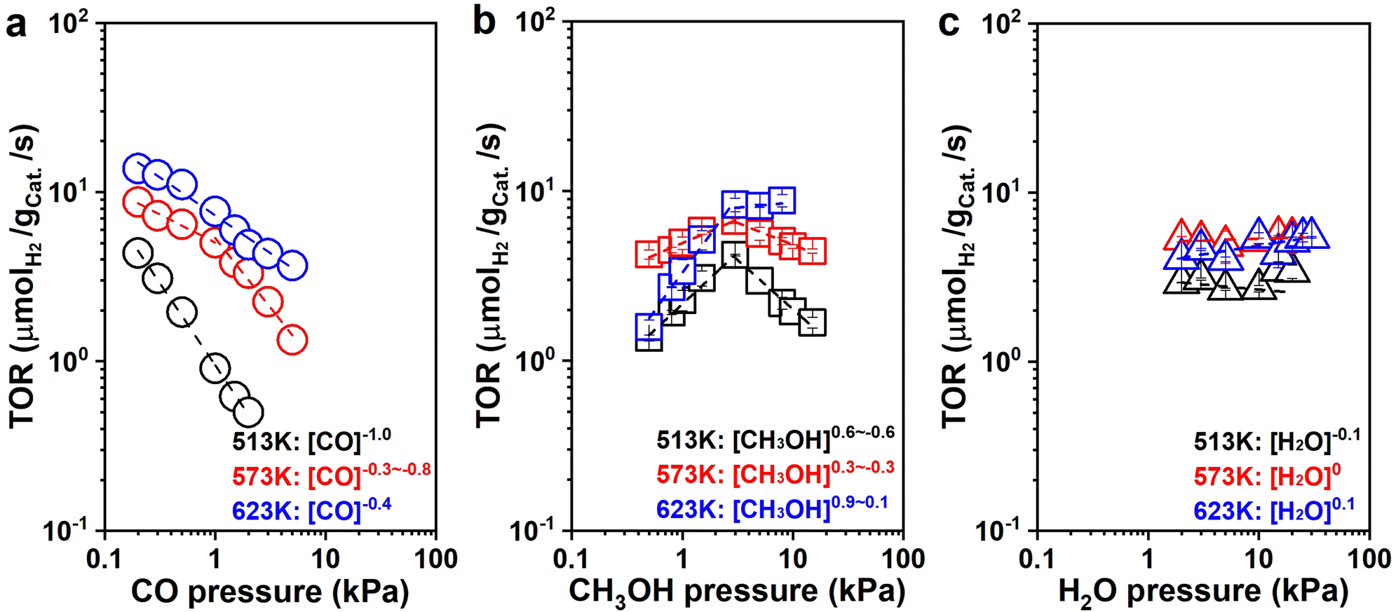 | ||
| Fig. 5 Pressure dependence study of MSR on NiCe/CN DAC. H2 formation rates as functions of the (a) CO pressures (○: 0.2–3 kPa CO, 1 kPa CH3OH, 16.02 kPa H2O), (b) CH3OH (□: 0.5–8 kPa CH3OH, 16.02 kPa H2O), and (c) H2O (△: 2–30 kPa H2O, 1 kPa CH3OH) of MSR reaction at different temperatures and atmospheric pressure. | ||
Simultaneously, the H2 formation rates were almost independent of H2O pressure with nearly zero-order dependencies at all three temperatures (513 K: rH2 ∼ [H2O]−0.1; 573 K: rH2 ∼ [H2O]0; 623 K: rH2 ∼ [H2O]0.1. Fig. 5c). This suggests that either H2O (or its derivatives: –OH) is abundant on the surface of the catalyst, or WGS is not significant during catalysis under this differential reaction condition. We have two methods to determine the contribution of WGS within the whole reaction network, one of which is to compare the selectivities of the carbonaceous species. For example, if the main product is CO2 rather than CO, WGS must be significant within the whole reaction process. If CO is the main species, the reaction would experience limited WGS. The other method is to check the ratio between H2 and CO (ε = fH2/fCO) within the downstream gases to decide the rate ratio between MD and WGS (η = rMD/rWGS), which was systematically discussed in Section 6 of the ESI† (ESI-S6). There was still a fair amount of CO during the kinetic measurement at low H2O pressure (<15 kPa, Fig. S17b, ESI†), which suggests that WGS is not probably significant under the reaction conditions in Fig. 5c. Therefore, under these conditions, we found that WGS has weak contributions to the formation of H2 during MSR with the H2O pressure increasing from 2 kPa to 15 kPa. The ε decreased from 8.9 to 1.6 (Fig. S17a, ESI†), which is consistent with the results learned from SSITKA. It is probable that WGS becomes significant once the total conversion is selectively promoted, which is quite similar to the condition reported in the literature.10,12 For example, as described in Fig. S18a (ESI†), ratios on the reaction rate of MD and WGS (ε) decreased from 1.2 to 1.0 once the reaction conversion was promoted from 7.7% to 99.1%, respectively.
As shown in Fig. S19a (ESI†), the H2 formation rates were also independent of the CO2 pressure with zero-order dependence at all three temperatures (513 K: rH2 ∼ [CO2]−0.1; 573 K: rH2 ∼ [CO2]0; 623 K: rH2 ∼ [CO2]0). Moreover, the CH3OH consumption rates were independent of H2 pressure with nearly zero-order dependence at all three conditions (513 K: rCH3OH ∼ [H2]0; 573 K: rCH3OH ∼ [H2]−0.1; 623 K: rCH3OH ∼ [H2]0, Fig. S19b, ESI†), suggesting that although CO2 and H2 are significant in the reaction system, the binding energy of CO2 and H2 or its derivatives (i.e., H*) is weaker than the MASIs promoted. It is worth noting that large amounts of H2 slightly inhibited the reaction activity, and it becomes more pronounced at lower temperatures.
To explore the intermediates on the catalyst surface under the condition of WGS and develop a deeper understanding of the reaction mechanism of MSR, pressure dependence studies for WGS were conducted. As shown in Fig. S20 (ESI†), the H2 formation rate increased with CO pressure below 0.8 kPa and then maintained essentially constant at 573 K with the CO pressure promoted, respectively (rH2 ∼ [CO]0.4–0). The initial positive dependence indicates that active sites are not saturated with CO, and the later zero-order dependence indicates that the CO* would be significant at high CO partial pressures. The H2 formation rate was independent of CO2 pressure with zero-order dependence (rH2 ∼ [CO2]0), suggesting that the CO2 is either negligible or significant on the surface of the catalyst. As the adsorption of CO2 is difficult from highly dispersed transition metals, we would suggest that the coverage of CO2 from the catalytic surface is negligible.65–67 The H2 formation rates increased with H2O pressure with the nearly first-order dependence (rH2 ∼ [H2O]0.6), then H2O or –OH may not be the MASIs on the surface of catalysts. The CO2 formation rates decreased with H2 pressure with the nearly negative first-order dependence (rCO2 ∼ [H2]−0.8), indicating that H2 or its derivatives (i.e., H*) may be significant on the surface of catalysts for the WGS reaction. This is slightly different from our previous Pt/NiAl2O4 reaction system detected.28
With all of the information received, a possible reaction pathway has been proposed, as shown in Scheme 1. We assume that the activation of CH3OH and H2O occurred at different active sites, with Ni and CeOx acting as the primary active sites for MD and WGS, respectively, resulting in the interface between Ni and CeOx as the critical active components of MSR. In Scheme 1, first, CH3OH dissociatively adsorbed to form methoxy groups (CH3O*) and protons (H*, * represents the Ni site). The methoxy groups on the Ni sites further dehydrogenate to CH2O* and H*, and CH2O* would undergo additional dehydrogenation steps to selectively generate CO. All protons would adsorb (or diffuse) to the Ni sites to form H*, the two of which would combine to create a molecularly adsorbed hydrogen and release one active site (*). Finally, the desorption of hydrogen would release another active site. In addition, we assume that H2O was activated at the oxygen vacancy (OV) of CeOx to form OLH groups and H*, which would further dehydrogenate to form OL and H*. The CO adsorbed on the Ni sites (CO*) would transfer to OL sites to form the COOL species, eventually releasing CO2 and regenerating the oxygen vacancies (OV). The H* would spontaneously diffuse to the Ni sites and release as H2.
 | ||
| Scheme 1 Proposed reaction pathway of MSR over NiCe/CN DAC. | ||
The detailed elementary steps are presented in Scheme S1 (ESI†), and the complete derivations of the rate expression for H2 formation in MD and WGS are listed in Section 7 of the ESI† (ESI-S7). It was hypothesized that the formation of CH2O* from the CH3O* dehydrogenation may be the kinetically relevant step (KRS) for MD, and the cracking of OLH may be the KRS for WGS:
| CH3O* + * → CH2O* + H* | (1) |
| OLH + * → H* + OL | (2) |
According to the assumption that MSR undergoes both MD and WGS processes, the expression of the H2 formation rates in MSR would be expressed as follows:
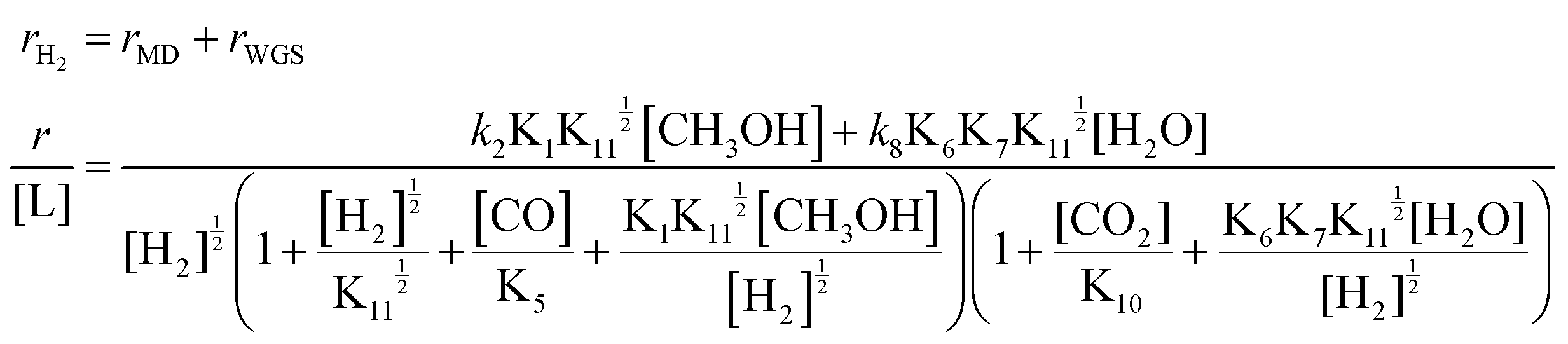 | (3) |
By assuming different surface species as the main surface intermediates, the expression (eqn (3)) could meet the pressure dependence results (Fig. 5 and Fig. S19, ESI†) very well. Thus, this MSR reaction might experience two parallel paths that contain MD and WGS, in which the rupture of C–H bond within CH3O* and the cracking of OLH are the KRSs, respectively.
099 h−1) is negligible.
| Isotope tracing | MSR | MD | WGS |
|---|---|---|---|
| D2O → H2O | 1.35 | — | 2.56 |
| CD3OD → CH3OH | 1.72 | 1.81 | — |
| CH3OD → CH3OH | 1.12 | 1.19 | — |
Similar to the rate expression of H2 formation in MSR (eqn (3)), the KIEs of MSR may also be described as the synergistic effect of the MD and WGS reactions:
| KIEMSR = α·KIEMD + β·KIEWGS | (4) |
Conclusions
A dual-atomic catalytic system has been selectively established following an incipient wetness impregnation method, in which isolated Ni and Ce sites have been decorated onto a carbon–nitrogen support. The dual-atomic structure has been confirmed by systematic characterizations, including FT-EXAFS and AC HAADF-STEM measurements. This NiCe/CN DAC catalyst shows excellent reaction activities in both WGS and MSR, and it gives 6.5 μmolH2 gcat.−1 s−1 of H2 generation rate and only 0.8% CO selectivity at complete methanol conversion at 513 K, superior to Ni/CeO2 and a series of noble-metal catalysts compared. The promoted reaction performance was tentatively attributed to the DAC structure and detailed electronic modification from isolated Ce to the adjacent Ni following quasi-in situ XPS analysis. In addition, systematic kinetic studies and SSITKA investigations suggest that the MD and WGS occurred on independent active sites. It is probable that CH3OH was mainly dissociatively adsorbed on the Ni surface to form CH3O*, and was followed by subsequent dehydrogenation to create CO*. The rupture of the C–H bond within CH3O* was assumed to be the KRS for the MD reaction. The OV over CeOx was assumed to be the main active component in the activation of H2O with the rupture of OL–H as the KRS for the WGS reaction, which would not be highly involved in the hydrogen production under differential conditions, while it would be very important to determine the reaction selectivities once the methanol conversion promoted. All of these assumptions were further confirmed by a series of KIE analyses. This atomic Ni–CeOx interfacial site does facilitate WGS and MSR reactions, and this work paves the way for rational active site design from atomic level.Experimental
Synthetic procedures
For the synthesis of NiCe/CN DAC, 21.6 g urea (American Chemical Society (ACS), Aladdin) was first dissolved in 20 ml ultrapure water. Then, 0.48 mmol Ni(NO3)2·6H2O (Analytical Reagent (AR), Aladdin) and 0.48 mmol Ce(NO3)3·6H2O (AR, Aladdin) were independently dissolved in the solution. After stirring for minutes, some pieces of melamine sponges were put into the solution and stirred for 70 min at room temperature. The sponges were taken out into a 50 ml centrifugal pipe, then rapidly frozen by liquid nitrogen. Subsequently, the samples were dried through vacuum freeze-drying and calcined in a tube furnace at 823 K under N2 for 4 h. The synthesis process of Ni/CN, Ce/CN, NiLa/CN and NiY/CN were similar to that of NiCe/CN with different metal precursors added. For the synthesis of Ni/CN and Ce/CN, only 0.48 mmol Ni(NO3)2·6H2O or 0.48 mmol Ce(NO3)3·6H2O were applied, respectively. For NiLa/CN or NiY/CN, Ce(NO3)3·6H2O was replaced by La(NO3)3·6H2O (AR, Aladdin) or Y(NO3)3·6H2O (AR, Aladdin), respectively. The catalysts with different Ni loadings were synthesized with various amounts of Ni(NO3)2·6H2O added (0.022 mmol for 0.1% NiCe/CN DAC, 0.109 mmol for 0.5% NiCe/CN DAC, 0.218 mmol for 1% NiCe/CN DAC and 0.654 mmol for 3% NiCe/CN DAC, respectively), while the same amount of Ce(NO3)3·6H2O (0.48 mmol) was used.53Characterizations
The morphologies of the as-received sample were characterized by TEM on a JEM-2800 microscope (JEOL, Japan), operating at an acceleration voltage of 200 kV. The fresh NiCe/CN DAC sample and sample after reaction were suspended in ethanol by ultra-sonication, and the suspension was then dropped onto the copper grid for TEM characterizations.The crystalline structures of the as-obtained samples were tested by XRD on a Rigaku Smart-lab X-ray diffractometer (Rigaku, Japan) with Cu Kα radiation (λ = 1.5406 Å, 20 mA and 40 kV).
N2 adsorption–desorption isotherms were obtained on Micromeritics APSP 2460 at 77 K, and Brunauer–Emmett–Teller (BET) method was used to calculate the surface area.
The element content was measured by inductively coupled plasma optical emission spectrometry (ICP-OES: Thermo Fisher iCAP PRO).
The thermogravimetric analysis of the NiCe/CN DAC sample after the reaction was carried out on a thermogravimetric analyzer (TGA 55). The sample was heated from room temperature to 1097 K at 10 K min−1 under the flow of N2 (40 mL min−1).
AC HAADF-STEM images were taken at 300 kV on a FEI-Titan Cubed Themis G2 300 scanning transmission electron microscope. The fresh NiCe/CN DAC sample was suspended in ethanol by ultra-sonication, and the suspension was then dropped onto the microgrids for AC HAADF-STEM characterization.
The atom size distribution was measured from the AC HAADF-STEM image, and nanoparticle size distribution was measured from the TEM image. The diameter (〈d〉) was calculated using the following equation:
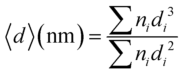 | (5) |
The XAS characterizations (including XANES and EXAFS) were recorded at the Singapore Synchrotron Light Source (SSLS) center, where a pair of channel-cut Si(111) crystals were utilized in the monochromator. The storage ring was working at 2.5 GeV with an averaged electron current of <200 mA. The acquired EXAFS results were extracted and processed according to the standard procedures with the ATHENA module implemented in the FEFIT software packages. The k3-weighted Fourier transform (FT) of x(k) in R space was obtained within the range of 0 to 14.0 Å by applying a Besse window function, and the prepared catalysts were not pre-treated prior to this characterization.
The change of the chemical state of the metal species on NiCe/CN DAC, Ni/CN SAC and Ni/CeO2 during the MSR was analyzed through the quasi-in situ XPS experiments, accomplished on a Thermo Scientific ESCALAB 250Xi photoelectron spectrometer equipped with a monochromatic microfocused Al-Kα X-ray source (1486.8 eV). Firstly, the catalyst was pressed into a small tablet and transferred into the pretreatment chamber, and activated under flowing 10 vol% H2/Ar (total flow rate: 50 mL min−1) at 623 K for 2 h. The activated sample was then cooled to room temperature and transferred directly into the chamber for XPS measurement without exposure to air. Then activated catalyst was diverted back to the pretreatment chamber and treated at 623 K under the flow of methanol steam (1 kPa CH3OH, Ar balanced, total flow rate: 30 mL min−1) for 1 h. After treatment, the catalyst was switched back to the chamber for XPS analysis at room temperature without exposure to air. At last, the above process was repeated and we introduced the methanol/water steam into the pretreatment chamber at 623 K for 1 h (1 kPa CH3OH, 16.02 kPa H2O, Ar balanced, total flow rate: 30 mL min−1), after which the final chemical state of the sample was determined (XPS analysis at room temperature).
Catalytic performance measurement
MSR and WGS reactions were performed in a continuous plug-flow reactor. In a typical catalytic measurement, 100 mg of catalysts were placed in the vertical quartz tube (i.d. 1 cm) mixed mechanically with 400 mg silica (Sigma Aldrich) and sandwiched by quartz wool. The temperatures of the transfer line and catalyst bed were controlled by the temperature controller (UDLAN, 516P) equipped with a K-type thermocouple, which was placed in the constant temperature area of the reactor and closed to the catalyst bed to monitor the reaction temperature. Flow rates of gases were conducted by mass flow controllers (MFC Sevenstar, D07). Liquid reactants (CH3OH, Saifuri, >99.9%; H2O, NJDULY) were fed by the syringe pumps (Longer, LSP01-1BH). Before the reaction, all catalysts were firstly pre-treated in flowing 10 vol% H2/Ar (total flow rate: 100 mL min−1) at 623 K for 2 h. As for MSR, a mixture of 10 wt% CH3OH/H2O was introduced to the evaporator by a syringe pump and carried to the catalyst bed by co-feeding Ar (1 kPa CH3OH, 16.02 kPa H2O, Ar balanced, total flow rate: 30 mL min−1), heated from 423 K to 623 K and the ramping rate was 10 K min−1. For WGS, Ar and CO were mixed and fed to the reactor regulated by mass flow controllers along with flowing water (2 kPa CO, 10 kPa H2O, Ar balanced, total flow rate: 80 mL min−1). The products were analyzed online by gas chromatography (GC-2014, Shimadzu) equipped with a flame ionization detector (FID, connected to an Rtx-1 capillary column) and a thermal conductivity detector (TCD, connected to MS-13x and Porapak-S columns), respectively. Conversion and product selectivity could be calculated by peak area from GC.The conversion of methanol (Conv.CH3OH) was calculated according to the equation, as follows:
 | (6) |
The selectivities of products were calculated according to the equation, as follows:
 | (7) |
 | (8) |
 | (9) |
The conversion of CO (Conv.CO) was estimated according to the equation, as follows:
 | (10) |
The turnover rate of mmol H2 product yield per second per gram catalyst was calculated according to the equation, as follows:
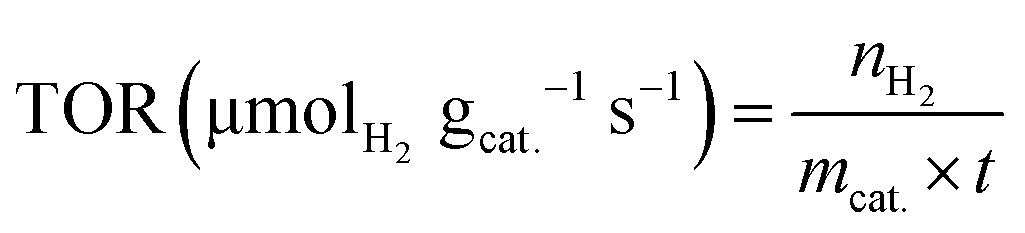 | (11) |
Steady-state isotopic transient kinetic analysis (SSITKA) combined with in situ FTIR measurements
SSITKA experiments were performed on the gas–solid transient reactor, equipped with two separate gas lines to control the labeled and unlabeled gas mixtures, respectively, and a four-way valve to ensure the quick switch of feed streams (<200 ms, steady-state was reached before switching). The reaction system was maintained in the absence of isotopic mass effect. The in situ FTIR measurements were performed on the spectrometer (BRUKER Tensor II) equipped with an MCT detector operated at atmospheric pressure. NiCe/CN DAC was pressed into self-supported wafer firstly, and then placed in the chamber and reduced at 623 K (heating ramp of 10 K min−1) for 1 h with 3 vol% H2/Ar. After purging by flowing Ar (50 mL min−1), the IR spectra were recorded once the 2 kPa CH3OH (Ar balanced, total flow rate: 50 mL min−1) was introduced to the chamber by a syringe pump (Longer, TJ-3A/W0109-1B). This condition was held for 50 min to reach a steady-state. Background spectra were recorded under this condition, and then the unlabeled reactant was switched to labeled reactant mixtures (e.g., 2 kPa CD3OD, Ar balanced, total flow rate: 50 mL min−1) for 50 min. The infrared spectra were continuously collected during this process. The IR spectra were recorded with the instrument resolution set at 4 cm−1, and 32 scans were applied and averaged for each spectrum. Isotope exchange experiments of water (10 kPa H2O was switched to 10 kPa D2O, Ar balanced, total flow rate: 100 mL min−1) and methanol with different pressures of water co-fed (2 kPa CH3OH + 10 kPa H2O was switched to 2 kPa CD3OD + 10 kPa H2O, 2 kPa CH3OH + 15 kPa H2O was switched to 2 kPa CD3OD + 15 kPa H2O, Ar balanced, total flow rate: 50 mL min−1) were carried out following the same procedure described above, but instead of recording the initial unlabeled reactant as background, the background was recorded after purging by flowing Ar.The residual coverage (Θdes) of surface species at time t was estimated by the equation below:
 | (12) |
Isotope tracing and kinetic isotope effects assessment
The kinetic isotope effects (KIEs) of MD, WGS and MSR on H2 formation were measured over 1% NiCe/CN DAC under steady-state conditions.As for MSR, CH3OH was replaced stepwise by CH3OD and CD3OD, while keeping the pressure of H2O constant (2 kPa H2O). Furthermore, H2O was replaced by D2O with the pressure of CD3OD remaining constant (1 kPa CD3OD). Finally, the reaction was switched to CD3OD + H2O, CH3OD + H2O, and CH3OH + H2O sequentially to estimate the deactivation during the measurements (1 kPa isotopes of CH3OH, 2 kPa isotopes of H2O, Ar balanced, 623 K, GHSV = 19099 h−1).
As for MD, CH3OH was replaced stepwise by CH3OD and CD3OD, and then returned to CH3OD and CH3OH with the pressure maintained at 1 kPa to estimate the deactivation during the measurements (1 kPa isotopes of CH3OH, Ar balanced, 623 K, GHSV = 19099 h−1).
As for WGS, H2O was initially replaced by D2O, and then switched to H2O with the CO pressure maintained at 2 kPa to estimate the catalytic deactivation (2 kPa CO, 10 kPa isotopes of H2O, Ar balanced, 623 K, GHSV = 19099 h−1).
Author contributions
Y. H. and Z. L. contributed equally to this work. Y. Z., H. Z. and Y. D. designed the research, Z. L. performed the materials preparation, HAADF-STEM and XAFS characterizations, Y. H. performed the kinetic studies, quasi-in situ XPS analysis and the SSITKA characterizations. All of the authors participated in the discussion of the results and the writing of the manuscript.Conflicts of interest
There are no conflicts to declare.Acknowledgements
We gratefully acknowledge the support from the National Natural Science Foundation of China (22371131, 21971117, 22172078), the 111 Project (B18030) from China, the Beijing-Tianjin-Hebei Collaborative Innovation Project (19YFSLQY00030), the Outstanding Youth Project of Tianjin Natural Science Foundation (20JCJQJC00130), the Key Project of Tianjin Natural Science Foundation (20JCZDJC00650), the Open Foundation of Guangxi Key Laboratory of State Key Laboratory of Featured Metal Materials and Life-cycle Safety for Composite Structures (Grant No. 2022GXYSOF07), the Functional Research Funds for the Central Universities, Nankai University (ZB19500202) and, Tianjin “131” Innovative Talent Team Construction Project, Tianjin Key Lab for Rare Earth Materials and Applications (ZB19500202), and the Haihe Laboratory of Sustainable Chemical Transformations, the opening fund of Key Laboratory of Rare Earths, Chinese Academy of Sciences.References
- K. Kumar, P. Daw and D. Milstein, Chem. Rev., 2022, 122, 385–441 CrossRef PubMed.
- P. Preuster, C. Papp and P. Wasserscheid, Acc. Chem. Res., 2017, 50, 74–85 CrossRef CAS PubMed.
- G. A. Olah, Angew. Chem., Int. Ed., 2005, 44, 2636–2639 CrossRef CAS PubMed.
- G. A. Olah, G. K. S. Prakash and A. Goeppert, J. Am. Chem. Soc., 2011, 133, 12881–12898 CrossRef CAS PubMed.
- K. Sordakis, C. Tang, L. K. Vogt, H. Junge, P. J. Dyson, M. Beller and G. Laurenczy, Chem. Rev., 2018, 118, 372–433 CrossRef CAS PubMed.
- D. R. Palo, R. A. Dagle and J. D. Holladay, Chem. Rev., 2007, 107, 3992–4021 CrossRef CAS PubMed.
- E. Alberico and M. Nielsen, Chem. Commun., 2015, 51, 6714–6725 RSC.
- J. Kothandaraman, S. Kar, A. Goeppert, R. Sen and G. K. S. Prakash, Top. Catal., 2018, 61, 542–559 CrossRef CAS.
- D. Li, X. Y. Li and J. L. Gong, Chem. Rev., 2016, 116, 11529–11653 CrossRef CAS PubMed.
- L. Chen, Z. Y. Qi, X. X. Peng, J. L. Chen, C. W. Pao, X. B. Zhang, C. C. Dun, M. Young, D. Prendergast, J. J. Urban, J. H. Guo, G. A. Somorjai and J. Su, J. Am. Chem. Soc., 2021, 143, 12074–12081 CrossRef CAS PubMed.
- L. Lin, W. Zhou, R. Gao, S. Yao, X. Zhang, W. Xu, S. Zheng, Z. Jiang, Q. Yu, Y. W. Li and C. Shi, Nature, 2017, 544, 80–83 CrossRef CAS PubMed.
- B. A. Peppley, J. C. Amphlett, L. M. Kearns and R. F. Mann, Appl. Catal., A, 1999, 179, 21–29 CrossRef CAS.
- B. A. Peppley, J. C. Amphlett, L. M. Kearns and R. F. Mann, Appl. Catal., A, 1999, 179, 31–49 CrossRef CAS.
- D. K. Kim and E. Iglesia, J. Phys. Chem. C, 2008, 112, 17235–17243 CrossRef CAS.
- B. Frank, F. C. Jentoft, H. Soerijanto, J. Krohnert, R. Schlogl and R. Schomacker, J. Catal., 2007, 246, 177–192 CrossRef CAS.
- C. J. Jiang, D. L. Trimm, M. S. Wainwright and N. W. Cant, Appl. Catal., A, 1993, 97, 145–158 CrossRef CAS.
- K. Ploner, M. Watschinger, P. D. K. Nezhad, T. Gotsch, L. Schlicker, E. M. Kock, A. Gurlo, A. Gili, A. Doran, L. Zhang, N. Kowitsch, M. Armbruster, S. Vanicek, W. Wallisch, C. Thurner, B. Klotzer and S. Penner, J. Catal., 2020, 391, 497–512 CrossRef CAS.
- D. D. Li, F. Xu, X. Tang, S. Dai, T. C. Pu, X. L. Liu, P. F. Tian, F. Z. Xuan, Z. Xu, I. E. Wachs and M. H. Zhu, Nat. Catal., 2022, 5, 99–108 CrossRef CAS.
- S. Lin, D. Xie and H. Guo, ACS Catal., 2011, 1, 1263–1271 CrossRef CAS.
- S. Lin, R. S. Johnson, G. K. Smith, D. Xie and H. Guo, Phys. Chem. Chem. Phys., 2011, 13, 9622–9631 RSC.
- N. Köwitsch, L. Thoni, B. Klemmed, A. Benad, P. Paciok, M. Heggen, I. Köwitsch, M. Mehring, A. Eychmüller and M. Armbrüster, ACS Catal., 2021, 11, 304–312 CrossRef.
- K. Xu, C. Ma, H. Yan, H. Gu, W. W. Wang, S. Q. Li, Q. L. Meng, W. P. Shao, G. H. Ding, F. R. Wang and C. J. Jia, Nat. Commun., 2022, 13, 2443 CrossRef CAS PubMed.
- M. Cargnello, N. L. Wieder, T. Montini, R. J. Gorte and P. Fornasiero, J. Am. Chem. Soc., 2010, 132, 1402–1409 CrossRef CAS PubMed.
- M. Friedrich, S. Penner, M. Heggen and M. Armbruster, Angew. Chem., Int. Ed., 2013, 52, 4389–4392 CrossRef CAS PubMed.
- K. Fottinger, J. A. V. Bokhoven, M. Nachtegaal and G. Rupprechter, J. Phys. Chem. Lett., 2011, 2, 428–433 CrossRef CAS.
- M. Xu, S. Y. Yao, D. M. Rao, Y. M. Niu, N. Liu, M. Peng, P. Zhai, Y. Man, L. R. Zheng, B. Wang, B. S. Zhang, D. Ma and M. Wei, J. Am. Chem. Soc., 2018, 140, 11241–11251 CrossRef CAS PubMed.
- Y. R. Wang, J. M. Ma, X. Y. Wang, Z. S. Zhang, J. H. Zhao, J. Yan, Y. P. Du, H. B. Zhang and D. Ma, ACS Catal., 2021, 11, 11820–11830 CrossRef CAS.
- X. Y. Wang, D. D. Li, Z. R. Gao, Y. Guo, H. B. Zhang and D. Ma, J. Am. Chem. Soc., 2023, 145, 905–918 CrossRef CAS PubMed.
- S. K. Kaiser, Z. Chen, D. F. Akl, S. Mitchell and J. Pérez-Ramírez, Chem. Rev., 2020, 120, 11703–11809 CrossRef CAS PubMed.
- S. Y. Yao, X. Zhang, W. Zhou, R. Gao, W. Q. Xu, Y. F. Ye, L. L. Lin, X. D. Wen, P. Liu, B. B. Chen, C. Ethan, J. H. Guo, Z. J. Zuo, W. Z. Li, J. L. Xie, L. Lu, J. K. Christopher, L. Gu, C. Shi, A. R. Jose and D. Ma, Science, 2017, 357, 389–393 CrossRef CAS PubMed.
- X. Zhang, M. Zhang, Y. Deng, M. Xu, L. Artiglia, W. Wen, R. Gao, B. Chen, S. Yao, X. Zhang, M. Peng, J. Yan, A. Li, Z. Jiang, X. Gao, S. Cao, C. Yang, A. J. Kropf, J. Shi, J. Xie, M. Bi, J. A. van Bokhoven, Y. Li, X. Wen, M. Flytzani-Stephanopoulos, C. Shi, W. Zhou and D. Ma, Nature, 2021, 589, 396–401 CrossRef CAS PubMed.
- L. Lin, Q. Yu, M. Peng, A. Li, S. Yao, S. Tian, X. Liu, A. Li, Z. Jiang, R. Gao, X. D. Han, Y. W. Li, X. D. Wen, W. Zhou and D. Ma, J. Am. Chem. Soc., 2021, 143, 309–317 CrossRef CAS PubMed.
- C. Mateos-Pedreroa, C. Azenha, D. A. P. Tanaka, J. M. Sousa and A. Mendes, Appl. Catal., B, 2020, 277, 119243 CrossRef.
- F. Bossola, T. Roongcharoen, M. Coduri, C. Evangelisti, F. Somodi, L. Sementa, A. Fortunelli and V. Dal Santo, Appl. Catal., B, 2021, 297, 120398 CrossRef CAS.
- H. J. Xi, X. N. Hou, Y. J. Liu, S. J. Qing and Z. X. Gao, Angew. Chem., Int. Ed., 2014, 53, 11886–11889 CrossRef CAS PubMed.
- X. H. Xu, K. P. Shuai and B. Xu, Catalysts, 2017, 7(6), 183 CrossRef.
- H. Zhang, J. M. Sun, V. L. Dagle, B. Halevi, A. K. Datye and Y. Wang, ACS Catal., 2014, 4, 2379–2386 CrossRef CAS.
- L. N. Chen, K. P. Hou, Y. S. Liu, Z. Y. Qi, Q. Zheng, Y. H. Lu, J. Y. Chen, J. L. Chen, C. W. Pao, S. B. Wang, Y. B. Li, S. H. Xie, F. D. Liu, D. Prendergast, L. E. Klebanoff, V. Stavila, M. D. Allendorf, J. H. Guo, L. S. Zheng, J. Su and G. A. Somorjai, J. Am. Chem. Soc., 2019, 141, 17995–17999 CrossRef CAS PubMed.
- S. Zhang, Y. X. Liu, M. K. Zhang, Y. Y. Ma, J. Hu and Y. Q. Qu, Nat. Commun., 2022, 13, 5527 CrossRef CAS PubMed.
- P. Hu, Y. Diskin-Posner, Y. Ben-David and D. Milstein, ACS Catal., 2014, 4, 2649–2652 CrossRef CAS.
- S. Li and J. Gong, Chem. Soc. Rev., 2014, 43, 7245–7256 RSC.
- H. Tian, X. Li, L. Zeng and J. L. Gong, ACS Catal., 2015, 5, 4959–4977 CrossRef CAS.
- H. Tian, C. L. Pei, Y. Wu, S. Chen, Z. J. Zhao and J. L. Gong, Appl. Catal., B, 2021, 293, 120178 CrossRef CAS.
- A. H. Braga, D. C. de Oliveira, A. R. Taschin, J. B. O. Santos, J. M. R. Gallo and J. M. C. Bueno, ACS Catal., 2021, 11, 2047–2061 CrossRef CAS.
- Y. S. Wang, C. S. Wang, M. Q. Chen, J. X. Hu, Z. Y. Tang, D. F. Liang, W. Cheng, Z. L. Yang, J. Wang and H. Zhang, Fuel, 2020, 279, 118449 CrossRef CAS.
- S. Chen, C. L. Pei and J. L. Gong, Energy Environ. Sci., 2019, 12, 3473 RSC.
- G. W. Wu, C. X. Zhang, S. R. Li, Z. Q. Huang, S. L. Yan, S. P. Wang, X. B. Ma and J. L. Gong, Energy Environ. Sci., 2012, 5, 8942 RSC.
- T. Wang, H. Y. Ma, L. Zeng, D. Li, H. Tian, S. N. Xiao and J. L. Gong, Nanoscale, 2016, 8, 10177 RSC.
- M. Q. Chen, D. F. Liang, Y. S. Wang, C. S. Wang, Z. Y. Tang, C. Li, J. X. Hu, W. Cheng, Z. L. Yang, H. Zhang and J. Wang, Int. J. Hydrogen Energy, 2021, 46, 21796–21811 CrossRef CAS.
- Y. S. Wang, D. F. Liang, C. S. Wang, M. Q. Chen, Z. Y. Tang, J. X. Hu, Z. L. Yang, H. Zhang, J. Wang and S. M. Liu, Renewable Energy, 2020, 160, 597–611 CrossRef CAS.
- C. S. Wang, Y. S. Wang, M. Q. Chen, J. X. Hu, Z. L. Yang, H. Zhang, J. Wang and S. M. Liu, Int. J. Hydrogen Energy, 2019, 44, 26888–26904 CrossRef CAS.
- L. P. Song, Z. Liang, M. Z. Sun, H. B. Long and D. Y. Ping., Energy Environ. Sci., 2022, 15, 3494 RSC.
- Z. Liang, L. P. Song, M. Z. Sun, H. B. Long and D. Y. Ping, Sci. Adv., 2021, 7, eabl4915 CrossRef CAS PubMed.
- L. L. Han, H. Cheng, W. Liu, H. Q. Li, P. F. Ou, R. Q. Lin, H. T. Wang, C. W. Pao, A. R. Head, C. H. Wang, X. Tong, C. J. Sun, W. F. Pong, J. Luo, J. C. Zheng and H. L. Xin, Nat. Mater., 2022, 21, 681–688 CrossRef CAS PubMed.
- L. L. Yin, S. Zhang, M. Z. Sun, S. Y. Wang, B. L. Huang and Y. P. Du, Adv. Mater., 2023, 35, 230248 Search PubMed.
- M. Han, N. Wang, B. Zhang, Y. J. Xia, J. Li, J. R. Han, K. L. Yao, C. C. Gao, C. N. He, Y. C. Liu, Z. M. Wang, A. Seifitokaldani, X. H. Sun and H. Y. Liang, ACS Catal., 2020, 10, 9725–9734 CrossRef CAS.
- Y. Xie, J. J. Chen, X. Wu, J. J. Wen, R. Zhao, Z. L. Li, G. C. Tian, Q. L. Zhang, P. Ning and J. M. Hao, ACS Catal., 2022, 12, 10587–10602 CrossRef CAS.
- M. Romeo, K. Bak, J. El Fallah, F. Le Normand and L. Hilaire, Surf. Interface Anal., 1993, 20, 508–512 CrossRef CAS.
- K. Ploner, M. Watschinger, P. D. K. Nezhad, T. Götsch, L. Schlicker, E. M. Köck, A. Gurlo, A. Gili, A. Doran, L. Zhang, N. Köwitsch, M. Armbrüster, S. Vanicek, W. Wallisch, C. Thurner, B. Klötzer and S. Penner, J. Catal., 2020, 391, 497–512 CrossRef CAS.
- J. S. Huberty and R. J. Madix, Surf. Sci., 1996, 360, 144–156 CrossRef CAS.
- A. Rezvani, A. M. Abdel-Mageed, T. Ishida, T. Murayama, M. Parlinska-Wojtan and R. J. Behm, ACS Catal., 2020, 10, 3580–3594 CrossRef CAS.
- R. C. Millikan and K. S. Pitzer, J. Am. Chem. Soc., 1958, 80, 3515–3521 CrossRef CAS.
- S. L. Shannon and J. G. Goodwin Jr, Chem. Rev., 1995, 95, 677–695 CrossRef CAS.
- R. J. Madon and M. Boudart, Ind. Eng. Chem. Fundam., 1982, 21, 438–447 CrossRef CAS.
- A. A. Peterson and J. K. Nørskov, J. Phys. Chem. Lett., 2012, 3, 251–258 CrossRef CAS.
- F. Solymosi and A. Berkó, J. Catal., 1986, 101, 458–472 CrossRef CAS.
- G. Wang, X. L. Jiang, Y. F. Jiang, Y. G. Wang and J. Li, ACS Catal., 2023, 13, 8413–8422 CrossRef CAS.
- M. Gomez-Gallego and M. A. Sierra, Chem. Rev., 2011, 111, 4857–4963 CrossRef CAS PubMed.
Footnotes |
| † Electronic supplementary information (ESI) available. See DOI: https://doi.org/10.1039/d3ey00225j |
| ‡ These authors contributed equally. |
| This journal is © The Royal Society of Chemistry 2024 |