
 Open Access Article
 This Open Access Article is licensed under a Creative Commons Attribution-Non Commercial 3.0 Unported Licence
Insights into a surface-modified Li(Ni0.80Co0.15Al0.05)O2 cathode by atomic layer fluorination for improved cycling behaviour†
Youn
Charles-Blin
abe,
Oumaima
Hatim
a,
Mélissa
Clarac
a,
Anne-Marie
Perbost
a,
Solveine
Liminana
a,
Laura
Lopez
a,
Olinda
Gimello
a,
Katia
Guérin
 c,
Marc
Dubois
c,
Michael
Deschamps
de,
Delphine
Flahaut
be,
Hervé
Martinez
be,
Laure
Monconduit
ae and
Nicolas
Louvain
*ae
c,
Marc
Dubois
c,
Michael
Deschamps
de,
Delphine
Flahaut
be,
Hervé
Martinez
be,
Laure
Monconduit
ae and
Nicolas
Louvain
*ae
aInstitut Charles Gerhardt Montpellier, Université de Montpellier, CNRS, 34095 Montpellier, France. E-mail: nicolas.louvain@umontpellier.fr
bCNRS/Univ. Pau & Pays Adour/E2S UPPA, Institut des Sciences Analytiques et de Physicochimie pour l'Environnement et les Matériaux - UMR 5254, 64000 Pau, France
cUniversité Clermont Auvergne, CNRS, Sigma Clermont, ICCF, 63000 Clermont-Ferrand, France
dCEMHTI, CNRS UPR 3079, Université d'Orléans, F45071 Orléans, France
eRéseau sur le Stockage Electrochimique de l'Energie (RS2E), FR CNRS 3459, 33 Rue Saint Leu, 80039 Amiens, France
First published on 25th April 2024
Abstract
Li(Ni0.80Co0.15Al0.05)O2 is a lithium-ion battery cathode, commercially available for more than twenty years, which is associated with high energy capacity and high energy density, with moderate power. Atomic layer fluorination (ALF) of Li(Ni0.80Co0.15Al0.05)O2 with XeF2 is performed to improve its cyclability. The ALF method aims at forming an efficient protecting fluorinated layer at the surface of the material, with a low fluorine content. Surface fluorinated Li(Ni0.80Co0.15Al0.05)O2 is characterized by X-ray diffraction, electron microscopy, 19F nuclear magnetic resonance, X-ray photoelectron spectroscopy, and galvanostatic measurements, and a fluorine content as low as 1.4 wt% is found. The presence of fluorine atoms improves the electrochemical performances of Li(Ni0.80Co0.15Al0.05)O2: cyclability, polarization and rate capability are improved. Operando infrared spectroscopy and post-mortem gas chromatography provide some insights into the origins of these improvements.
The fabrication of robust interfaces between electrodes and electrolytes in various electrochemical systems is one of the great challenges for chemists.1–3 Incremental contributions are made by controlling surface chemistry and passivation layers.4 Such incremental improvements have made Li-ion batteries what they are today: nearly ubiquitous. Since the assembly of the first Li-ion battery by Yoshino et al. with a carbon anode and LiCoO2 cathode,5 surface protection has been applied to both electrode materials in order to mitigate irreversible side reactions from electrolytes.6–13 Intensive works have been devoted to the understanding of those degradation mechanisms, especially on the carbon anode side.14 The voltage of lithium insertion into carbon is relatively close to the Li+/Li reference, and, at such a potential, solvents of the electrolyte are not stable, are reduced and form a passiving layer on the carbon electrode, the solid–electrolyte interphase (SEI).15–17 Understanding the mechanism led to solutions being proposed to improve the electrodes: layers of oxynitrides on carbon,18 amorphous carbon on graphite anodes,19 surface oxidation and metal oxide coatings,20,21 and surface fluorination of carbon anodes.6,15,20,22,23 The formation of an SEI layer at the end of the first discharge in graphite-based anodes prevents the co-intercalation of solvents or other species along with lithium ions between the graphite sheets, and improved interfaces made this process more efficient.17 Nakajima et al. demonstrated that surface fluorination of the carbon anode could improve the first irreversible capacity and cyclability of carbon anodes of Li-ion batteries by modifying the chemical pendant groups at graphite and/or amorphous carbon edges, thus reducing the reactivity of the pendant groups towards the electrolyte.20 Reactions of the electrolyte with the surface of cathode particles are also known to be the major contributor to Li-ion capacity fading,24 and surface protection was applied to limit the decomposition reactions on the cathode side.7,12,13,25–31
Li(Ni0.80Co0.15Al0.05)O2, so-called NCA, is a well-known high-voltage layered oxide material used as a cathode of lithium-ion batteries conventionally prepared by the co-precipitation method. Although the electrochemical performances of NCA are already good, NCA still needs improvements to satisfy the requirements of high performance Li-ion batteries.32,33 It is known that at the end of the charging process, above 4.0 V, unstable Ni4+ ions existing in highly delithiated phases such as Li1−dNi0.80Co0.15Al0.05O2 will induce a quick transformation towards the more stable NiO-type rock salt phase, releasing oxygen through the decomposition of NCA, and resulting in capacity fading and potential safety hazard.34 One effective solution is to coat NCA with a passivating layer.30,32,35–37 Ideally, this coating is thin and uniform, Li-ion conducting, chemically inert, and does not affect the pore size and pore accessibility by the electrolyte. The recent literature demonstrates the importance of coatings for improved cycling performances, but we propose to study the origin of the improvements.
The importance of the fluorination of interphases in the battery performance is now gradually accepted in the community. A new consensus is taking place: how should the interphases be fluorinated?26 Here we proposed our atomic layer fluorination (ALF) method in order to provide a thin fluorinated layer at the surface of NCA. It is known that atomic fluorine can diffuse deeply within the first few nanometres of a particle, and it should cover all outer and inner surfaces of NCA grains. We followed the impact of our ALF protection on NCA cycling with help from operando infrared spectroscopy and post-mortem gas chromatography.
The surface modification of NCA was performed by following our reported ALF protocol.38,39 In a typical treatment performed in a thick-walled PTFE reactor, NCA is subjected to vapours of xenon difluoride, XeF2, which are released thanks to the following equilibrium:
| XeF2 (s) = XeF2(g) | (1) |
This equilibrium allows a continuous supply of gaseous XeF2. It decomposes onto the NCA surface according to:40–44
| XeF2 (g) = Xe (g) + 2 F˙ | (2) |
| 2 F˙ = F2 (g). | (3) |
Heating, at the surface of a reactive material, or under UV irradiation,42 favours decomposition. While other solid-state fluorinating agents could be selected to achieve surface fluorination, xenon difluoride can be employed at room temperature and requires neither nickel nor Monel alloy equipment, which would be more expensive, and more hazardous, than PTFE reactors at the lab scale. Moreover, no purification is required to remove by-products; only xenon gas (Xe(g)) is formed contrary to MFn−1(s) produced by other MFn(s) fluorinating agents (MFn, e.g. TbF4, CeF4, CoF3, etc.).
The release of F˙ is constant and moderate because of the low saturating steam pressure of XeF2 (3.8 mmHg at 25 °C).44 The fluorination rate is controlled by the reaction duration rather than by the molar ratio XeF2/NCA (constant under our conditions; Table S1†); durations of 1 h 30 min and 3 h 30 min were selected to achieve different fluorination rates, corresponding to NCA-F1 and NCA-F2 samples, respectively. While the exact reaction of xenon difluoride and NCA is difficult, if not impossible, to anticipate, it seems reasonable to assume that fluorine will react with lithium. The expected main reaction with NCA could be written as follows:
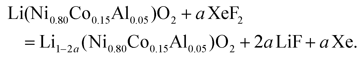 | (4) |
We recently demonstrated that atomic layer fluorination of lithium titanate Li4Ti5O12 leads to the formation of Li–F environments at the surface of the oxide.39 Considering the presence of lithium ions in the structure of NCA, the reaction might proceed according to eqn (4). If the amount of fluorinating agent is kept low compared to NCA, we expect that the atomic fluorine will interact with the surface of NCA, and will attract lithium ions in order to create passivating, i.e. protecting, Li–F environments on the surface of NCA particles, as in the case of LTO.39 Therefore, through the assumption of synthesis conditions, we designed and obtained a surface fluorinated NCA cathode material by our ALF method (Table S1†).
X-ray diffraction (XRD) patterns displayed in Fig. 2 confirm that the commercial NCA sample corresponds to crystalline layered oxide, consistent with the layered structure α-NaFeO2, as shown by the intense peaks at 2θ = 18.8°, 36.7°, 38.4°, 44.5°, 48.7°, 58.8°, 65.0°, and 68.3°, corresponding to (003), (101), (012), (104), (015), (107), (110), and (113) hkl planes, respectively (ICSD #238949). When subjected to XeF2 vapours for 1 h 30 min (NCA-F1) or 3 h 30 min (NCA-F2) at room temperature, the NCA structure does not seem to evolve, with no appearance of crystalline fluorinated phases. All three patterns can be indexed based on the R![[3 with combining macron]](https://www.rsc.org/images/entities/char_0033_0304.gif) m space group, and the refined cell parameters for NCA, NCA-F1, and NCA-F2 are identical (Fig. S0 and Table S2†). While no obvious influence of XeF2 on the crystal structure of NCA can be evidenced by XRD, the presence of fluorine is demonstrated by SEM-EDX (Fig. S1 and S2†). The morphology and size of particles and aggregates are not impacted by the fluorination procedure as expected (Fig. S1†), and EDX clearly shows that the distribution of F atoms is homogeneous over the NCA particles (Fig. S2†).
m space group, and the refined cell parameters for NCA, NCA-F1, and NCA-F2 are identical (Fig. S0 and Table S2†). While no obvious influence of XeF2 on the crystal structure of NCA can be evidenced by XRD, the presence of fluorine is demonstrated by SEM-EDX (Fig. S1 and S2†). The morphology and size of particles and aggregates are not impacted by the fluorination procedure as expected (Fig. S1†), and EDX clearly shows that the distribution of F atoms is homogeneous over the NCA particles (Fig. S2†).
Fig. 1 displays the 19F solid-state NMR spectra for NCA-F1 and NCA-F2 samples. As already reported, 6 wt% of PTFE is added to the NMR sample.39 This PTFE is used as an internal reference to quantify the amount of fluorine present in each surface fluorinated sample. NMR provides information about the local environments of the fluorine atoms within the material. Each spectrum was reconstructed using two lines located approximately at −44 ppm and −123 ppm (including several spinning sidebands). The main contribution, at −44 ppm, is assigned to the PTFE internal reference. The second signal at −123 ppm can therefore be attributed to the fluorine from surface fluorinated NCA samples, NCA-F1 and NCA-F2. As expected from eqn (4), it may originate from fluorine atoms located in the vicinity of lithium ions, as it corresponds to the 19F NMR shift of LiF. While this may mean that F atoms are in an environment closely related to the one found in crystalline cubic LiF (i.e. 6 fluorides surrounding 1 lithium ion, and 6 lithium ions surrounding 1 fluoride), it could also be understood in terms of “Li–F” species spread over the surface of NCA fluorinated particles, as we found for LTO.39 By using the NMR signal from PTFE as a reference, it is possible to integrate the intensities of the reconstructed spectra. In all samples containing 6 wt% of PTFE, the fluorine content can be deduced, considering only one type of F environment modelled with a single Gaussian line-shape (Table S3†). According to the fitting and the calculations derived from it, the NCA-F1 sample contains 0.8 wt% of fluorine, after integration of the NMR data, and the NCA-F2 sample contains 1.4 wt% of fluorine. When considering eqn (4), the chemical formulas of NCA-F1 and NCA-F2 could be expressed as Li0.96(Ni0.80Co0.15Al0.05)O2; 0.04 LiF and Li0.93(Ni0.80Co0.15Al0.05)O2; 0.07 LiF, respectively.
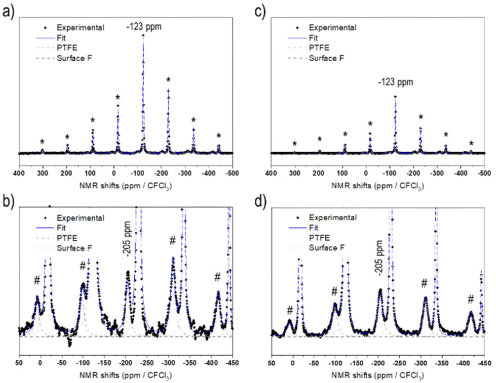 | ||
| Fig. 1 19F NMR spectra of fluorinated NCA samples (all samples contain 6 wt% of PTFE as an internal reference, and its main peak is indicated by the grey arrow): NCA-F1 (a), and a zoom-in view of the LiF-type signature (b), NCA-F2 (c), and a zoom-in view of the LiF-type signature (d). */# mark spinning sidebands for PTFE and LiF signals, respectively. | ||
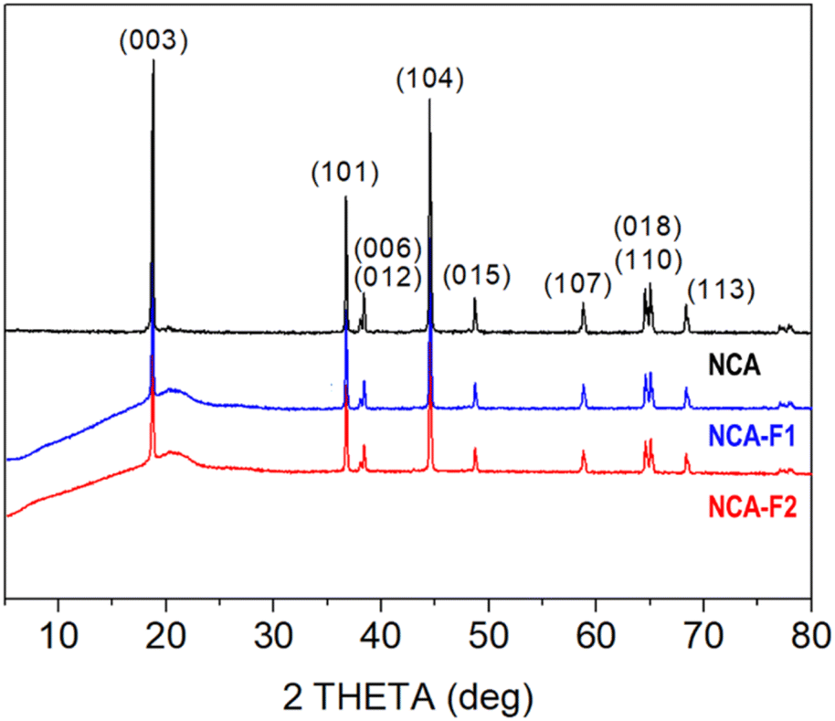 | ||
| Fig. 2 XRD patterns of pristine NCA and fluorinated samples. | ||
The surface of the bare and fluorinated NCA samples was analysed by X-ray photoelectron spectroscopy (XPS) to identify the fluorinated species formed. The results are displayed in Fig. S3.† The pristine NCA sample displays characteristic peaks expected for Li(Ni0.80Co0.15Al0.05)O2. The F 1s core peaks of NCA-F1 are composed of 3 components: a strong proportion of Li–F located at 685.5 eV accounting for 1.1 at%, and two components at a higher binding energy, 687.5 eV (0.2 at%) related to fluorine atoms in an oxygenated environment of a solid solution of surface fluorinated NCA,39,45 and 689.5 eV (0.1 at%) attributed to CFx environments that might be stemming from partial fluorination of chemisorbed surface carbonate groups.45,46 A fourth component, not attributed, at 691.3 eV (0.2 at%) is necessary to reconstruct the F 1s spectrum of NCA-F2. This component most probably comes from charge artifacts and may not represent any chemical species. The intense XPS F 2s and 2p valence bands (Fig. S3†) indicate that the fluorination of NCA samples has occurred over more than the first 5 nm from the surface. The fluorination rates obtained from the atomic percentage ratios issued from XPS quantitative analyses are FLi–F/LiLi–F = 0.26 (0.04 from NMR) and 0.38 (0.07 from NMR) for NCA-F1 and NCA-F2, respectively (Table S4†). Those results indicate that XPS is concordant with solid-state NMR and defines the surface species as Li–F environments. Moreover, XPS detects more fluorine than NMR. The latter being sensitive to the whole volume of the sample, we can conclude that the fluorine atoms of NCA-F1 and NCA-F2 samples are located at the surface or within the first 5 to 10 nm of the surface. Finally, it must be noted that XPS detects fluorine in oxygenated environments (0.2 wt%), so that the chemical formula may be more accurate as:
| Li0.96−x(Ni0.80Co0.15Al0.05)O2−xFx; 0.04 LiF for NCA-F1 |
| Li0.93−x(Ni0.80Co0.15Al0.05)O2−xFx; 0.07 LiF for NCA-F2. |
Coin cells of NCA, NCA-F1, and NCA-F2 were prepared, and lithium insertion/deinsertion properties were evaluated versus lithium metal. The galvanostatic charge–discharge profiles of the first cycle of each sample were measured at C/5 (with C being equal to 280.7 mA g−1, and C/5 meaning 1 Li+ ion inserted in 5 h) between 2.5 and 4.5 V vs. Li+/Li are displayed in Fig. 3a. The profiles are in good accordance with the expected behaviour of NCA as the cathode of the Li-ion system.31,36 The initial discharge capacities were found to be 181, 188, and 181 mA h g−1 for NCA, NCA-F1, and NCA-F2, respectively. This increase of the capacity on the first cycle for NCA-F1 is a global trend observed for other surface-modified NCA electrodes, and no clear explanations are provided in the recent literature on the origin of this improved behaviour.32,47
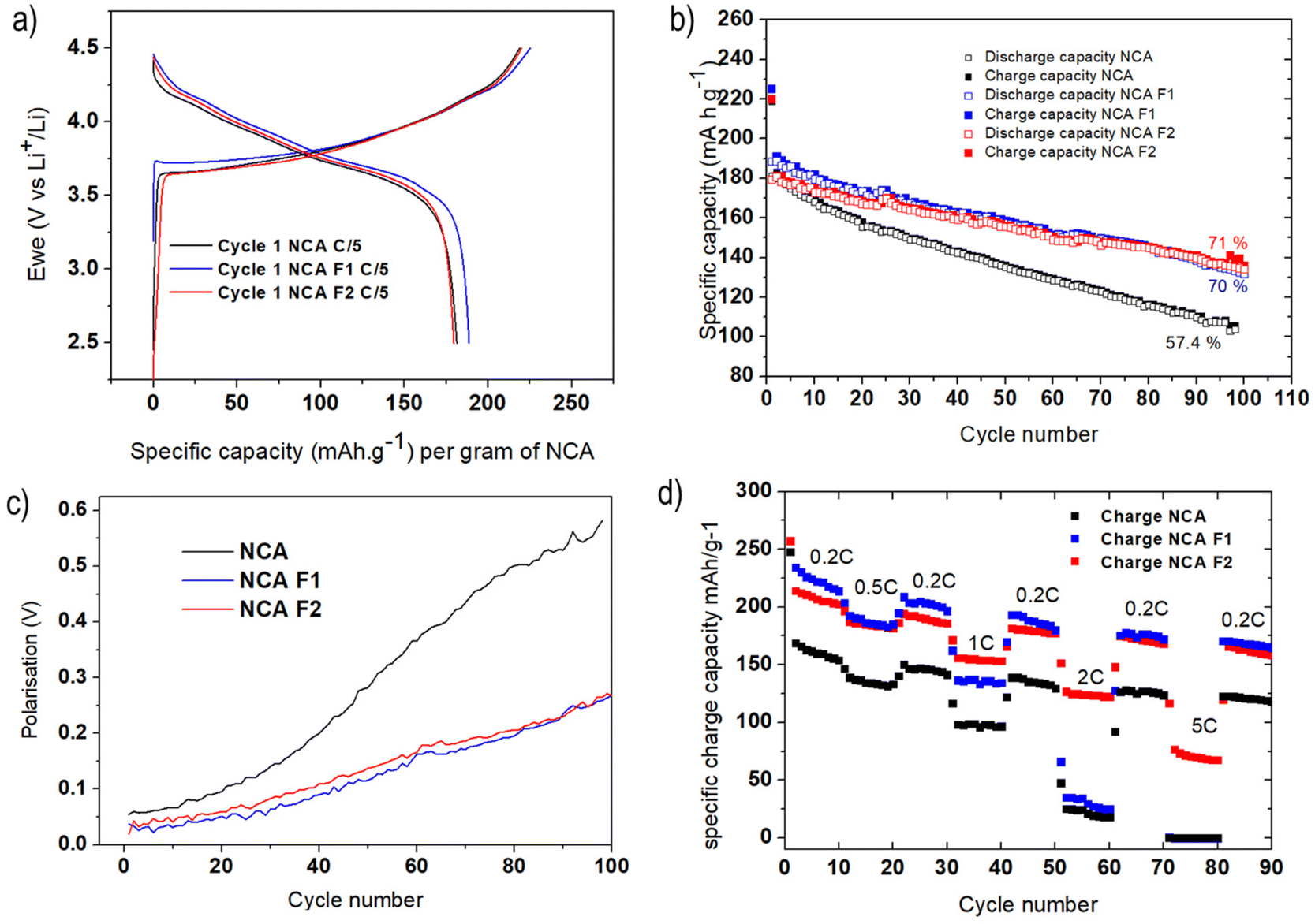 | ||
| Fig. 3 Galvanostatic voltage profiles of NCA/Li, NCA-F1/Li, and NCA-F2/Li cells cycled at C/5 between 4.5 and 2.5 V versus Li+/Li; the first cycle is displayed (a); specific charge capacity of NCA/Li, NCA-F1/Li, and NCA-F2/Li cells cycled at C/5 (b); polarisation as a function of the cycle number for NCA, NCA-F1 and NCA-F2 cells (c); and current rate capability of NCA, NCA-F1, and NCA-F2 electrodes (d). | ||
While their first cycle is similar, the slightly increased capacity of NCA-F1 being put aside, Fig. 3b shows that the cyclability of NCA-F1 and NCA-F2 is superior to the one of NCA. After 100 cycles, surface-fluorinated material electrodes approximately 70% of their initial charging capacity, while NCA loses nearly 50% of it. The polarisation, i.e. the difference between the average charge and discharge voltage, measured at half-charge/discharge capacity, is smaller for NCA-F1 and NCA-F2 than for NCA, being twice smaller after 100 cycles (Fig. 3c). Improved polarisation usually comes from the presence of a lithium-ion conducting layer at the electrode–electrolyte interphase.7 With higher applied current densities (Fig. 3d), both NCA-F1 and NCA-F2 display improved capacities up to 1C when compared with NCA, for which the capacity drop is important (less than 50 mA h g−1 at 2C, and nearly 0 mA h g−1 at 5C). It is noteworthy that capacity retention is somewhat higher for all samples when cycled at increasing current densities (Fig. 3d) than it is after 100 cycles at 0.2C (Fig. 3b). Moreover, it must be added that NCA electrodes, under the present experimental conditions, do not cycle well at 1C (Fig. S4†), and a preparation cycle at 0.2C is necessary (Fig. S5†). At this stage, the cycling behaviour of NCA is clearly improved by surface fluorination.
Operando Fourier-transform infrared spectroscopy in the attenuated total reflection (ATR-FTIR) mode was performed on adapted cells for NCA and NCA-F1 to study the electrolyte behaviour at the vicinity of the cathode during cycling (Fig. S6–S13†). In situ and/or operando FTIR is an efficient method to study battery electrodes and electrolytes.48–58 In our configuration, the electrolyte at the vicinity of the cathode can be studied and followed during charge/discharge cycles through a hole in the electrode. The difference between two FTIR spectra is calculated according to eqn (5):
| ΔR/R = (Rn − R0)/R0 | (5) |
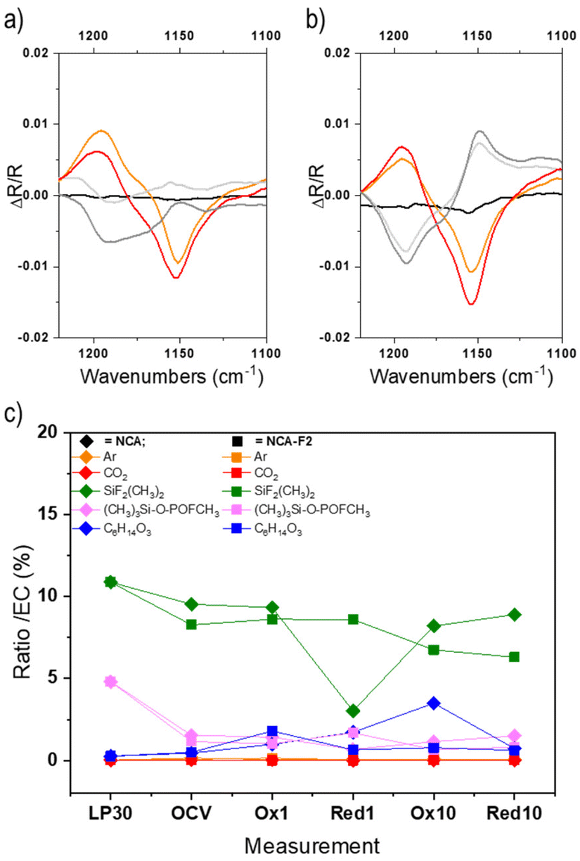 | ||
| Fig. 4 Operando ATR-FTIR signal of a selected region corresponding to the C–O stretching vibration of EC (1153 cm−1) collected for NCA (a) and NCA-F1 (b). Displayed spectra are recorded at the beginning of the charge (black), the end of the first charge (orange), the end of the first discharge (light grey), the end of the second charge (red), and the end of the second discharge (dark grey). The ratio of each LP30 component (area%) compared to EC as derived from GC-MS measurements (for all chromatograms, the relative abundance of the peak attributed to EC was always the highest and therefore normalized to 100%) for LP30/acetonitrile, NCA, and NCA-F1 (c). Please refer to the ESI† for further details. | ||
To further understand the impact of the ALF method on NCA cathodes, we endeavoured to study electrolytes of pristine and fluorinated cathodes by post-mortem GC-MS analysis (Fig. 4c, Fig. S14, S15 and Table S5†). The GC-MS analysis of the pristine LP30 electrolyte (LiPF6 1 M in EC![[thin space (1/6-em)]](https://www.rsc.org/images/entities/char_2009.gif) :DMC) in the presence of a piece of glass fibre separator (Fig. S15†) confirms the 1:1 ratio of EC:DMC (Table S5†) and the presence of (CH3)2F2Si, (CH3)3Si-O-POFCH3, and bis(2-methoxyethyl) ether. The presence of fluorinated silane and phosphate is a consequence of the formation of HF within the electrolyte, most probably from the decomposition of the PF6− species in the presence of water. HF can react with silica from the glass fibre, and those fluorinated species could be considered as a direct indicator of HF.59 The ether might stem from the decomposition of EC.60–63
:DMC) in the presence of a piece of glass fibre separator (Fig. S15†) confirms the 1:1 ratio of EC:DMC (Table S5†) and the presence of (CH3)2F2Si, (CH3)3Si-O-POFCH3, and bis(2-methoxyethyl) ether. The presence of fluorinated silane and phosphate is a consequence of the formation of HF within the electrolyte, most probably from the decomposition of the PF6− species in the presence of water. HF can react with silica from the glass fibre, and those fluorinated species could be considered as a direct indicator of HF.59 The ether might stem from the decomposition of EC.60–63
For the post-mortem analysis of electrolytes taken after OCV, 1st and 10th charges and discharges, the first interesting, but unexplained, feature is the loss of the 1:1 ratio of EC:DMC (Fig. S14g†). The quantity of DMC varies from 50 to 75% for NCA, and with a larger amplitude for fluorinated NCA (from 50 to 140%). DMC seems to react more than EC onto the NCA surface during cycling. The difference in reactivity of EC onto NCA or NCA-F is evident for the 10th charge. The electrolyte reaction mechanism obviously differs when the cathode surface is fluorinated. Moreover, while the presence of HF is noticeable in LP30, the quantities of (CH3)2F2Si and (CH3)3Si-O-POFCH3 are lower in the case of both cycled electrolytes extracted from NCA and fluorinated NCA (Fig. 4c). In both systems, these fluorinated silane and phosphate might take part in the formation of the electrode–electrolyte interphase, but this point is scarcely documented in the literature. The amount of the fluorinated silane is slightly higher over the cycling of NCA, compared to fluorinated NCA (except for the first discharge). (CH3)2F2Si, and (CH3)3Si-O-POFCH3 to some extent, is more likely to deposit on the surface-modified cathode than on the pristine NCA. A study of the cathode surface will surely provide even more insights into the cathode reactivity and could help to unravel some complex mechanisms of electrolyte reactions at the surface of the positive electrode.
The ALF method surely brings new outlooks for the short to mid-term future of Li-ion batteries. It modifies the surface of cathode particles with low amounts of extrinsic atoms through a gas–solid fluorination reaction that could be easily scaled up with an appropriate fluorinating agent – any metal fluoride MF3 (M = Mn, Fe, Co, etc.) can release atomic fluorine under heat treatment. Though the amount of F atoms incorporated into the compound is low, with no trace of structural modification from XRD, the electrochemical properties are improved. Operando ATR-FTIR provides an insight into the influence of the ALF coating on the electrolyte reactivity during cycling, as confirmed by post-mortem GC-MS measurements. These preliminary results on NCA cathodes encourage us to follow the path of surface-modified cathodes by our atomic layer fluorination method.
Conflicts of interest
There are no conflicts to declare.Acknowledgements
Oumaima Hatim wants to thank the Agence Nationale de la Recherche (GANDALF project, grant ANR-20-CE05-0042) for her PhD grant. The "Réseau des Rayons X et Gamma" (University of Montpellier, France) is gratefully thanked for granting access to their XRD platform. The authors thank the French National Research Agency (STORE-EX Labex Project ANR-10-LABX-76-01) for financial support. MD and NL are indebted to the IR-RMN-THC FR3050 CNRS for the spectrometer time access and the financial support of the NMR experiments.References
- P. Yang and J. M. Tarascon, Nat. Mater., 2012, 11, 560–563 CrossRef CAS PubMed.
- Y. W. Chen, J. D. Prange, S. Duhnen, Y. Park, M. Gunji, C. E. Chidsey and P. C. McIntyre, Nat. Mater., 2011, 10, 539–544 CrossRef CAS PubMed.
- J. M. Tarascon and M. Armand, Nature, 2001, 414, 359–367 CrossRef CAS PubMed.
- J. B. Goodenough and K. S. Park, J. Am. Chem. Soc., 2013, 135, 1167–1176 CrossRef CAS PubMed.
- A. Yoshino, K. Jitsuchika and T. Nakashima, Jp. Pat., 1989293, 1985 Search PubMed.
- H. Groult, T. Nakajima, L. Perrigaud, Y. Ohzawa, H. Yashiro, S. Komaba and N. Kumagai, J. Fluorine Chem., 2005, 126, 1111–1116 CrossRef CAS.
- J. S. Park, A. U. Mane, J. W. Elam and J. R. Croy, ACS Omega, 2017, 2, 3724–3729 CrossRef CAS PubMed.
- K. Matsumoto, T. Fukutsuka, T. Okumura, Y. Uchimoto, K. Amezawa, M. Inaba and A. Tasaka, J. Power Sources, 2009, 189, 599–601 CrossRef CAS.
- L. Croguennec, J. Bains, M. Menetrier, A. Flambard, E. Bekaert, C. Jordy, P. Biensan and C. Delmas, J. Electrochem. Soc., 2009, 156, A349–A355 CrossRef CAS.
- M. Ménétrier, J. Bains, L. Croguennec, A. Flambard, E. Bekaert, C. Jordy, P. Biensan and C. Delmas, J. Solid State Chem., 2008, 181, 3303–3307 CrossRef.
- Y. K. Sun, S. W. Cho, S. T. Myung, K. Amine and J. Prakash, Electrochim. Acta, 2007, 53, 1013–1019 CrossRef CAS.
- J. S. Park, A. U. Mane, J. W. Elam and J. R. Croy, Chem. Mater., 2015, 27, 1917–1920 CrossRef CAS.
- X. Fan, L. Chen, X. Ji, T. Deng, S. Hou, J. Chen, J. Zheng, F. Wang, J. Jiang, K. Xu and C. Wang, Chem, 2018, 4, 174–185 CAS.
- A. Du Pasquier, F. Disma, T. Bowmer, A. S. Gozdz, G. Amatucci and J. M. Tarascon, J. Electrochem. Soc., 1998, 145, 472–477 CrossRef.
- T. Nakajima, J. Fluorine Chem., 2000, 105, 229–238 CrossRef CAS.
- A. Wang, S. Kadam, H. Li, S. Shi and Y. Qi, npj Comput. Mater., 2018, 4, 15 CrossRef.
- S. J. An, J. Li, C. Daniel, D. Mohanty, S. Nagpure and D. L. Wood, Carbon, 2016, 105, 52–76 CrossRef CAS.
- K. I. Chung, J. G. Park, W. S. Kim, Y. E. Sung and Y. K. Choi, J. Power Sources, 2002, 112, 626–633 CrossRef CAS.
- Y. S. Park, H. J. Bang, S. M. Oh, Y. K. Sun and S. M. Lee, J. Power Sources, 2009, 190, 553–557 CrossRef CAS.
- T. Nakajima, Solid State Sci., 2007, 9, 777–784 CrossRef CAS.
- Y. K. Choi, K. I. Chung, W. S. Kim, Y. E. Sung and S. M. Park, J. Power Sources, 2002, 104, 132–139 CrossRef CAS.
- G. Chen, Z. N. Shi, J. Y. Yu, J. L. Xu, X. W. Hu, Z. W. Wang and B. L. Gao, J. Electrochem. Soc., 2015, 162, C197–C204 CrossRef CAS.
- T. Nakajima, J. Fluorine Chem., 2007, 128, 277–284 CrossRef CAS.
- W. T. Li and B. L. Lucht, J. Electrochem. Soc., 2006, 153, A1617–A1625 CrossRef CAS.
- Y. K. Sun, M. J. Lee, C. S. Yoon, J. Hassoun, K. Amine and B. Scrosati, Adv. Mater., 2012, 24, 1192–1196 CrossRef CAS PubMed.
- C. Wang, Y. S. Meng and K. Xu, J. Electrochem. Soc., 2019, 166, A5184–A5186 CrossRef CAS.
- S. Xia, F. Li, F. Cheng, X. Li, C. Sun, J.-J. Liu and G. Hong, J. Electrochem. Soc., 2018, 165, A1019–A1026 CrossRef CAS.
- C. Liu, K. Qian, D. Lei, B. Li, F. Kang and Y.-B. He, J. Mater. Chem. A, 2018, 6, 65–72 RSC.
- D. W. Kim, H. Shiiba, N. Zettsu, T. Yamada, T. Kimijima, G. Sanchez-Santolino, R. Ishikawa, Y. Ikuhara and K. Teshima, NPG Asia Mater., 2017, 9, 10 Search PubMed.
- J. W. Lee and Y. J. Park, J. Electrochem. Sci. Technol., 2016, 7, 263–268 CrossRef CAS.
- Y. Huang, X. Zhang, R. Yu, S. Jamil, S. Cao, S. Fang, Y. Wang, K. Tang, G. Chen, Z. Luo, X. Yang and X. Wang, ACS Appl. Mater. Interfaces, 2019, 11, 16556–16566 CrossRef CAS PubMed.
- L. Zhu, Y. Liu, W. Y. Wu, X. W. Wu, W. P. Tang and Y. P. Wu, J. Mater. Chem. A, 2015, 3, 15156–15162 RSC.
- N. Kimiaie, K. Wedlich, M. Hehemann, R. Lambertz, M. Müller, C. Korte and D. Stolten, Energy Environ. Sci., 2014, 7, 3013–3025 RSC.
- D. P. Abraham, R. D. Twesten, M. Balasubramanian, I. Petrov, J. McBreen and K. Amine, Electrochem. Commun., 2002, 4, 620–625 CrossRef CAS.
- S.-H. Lee, C. S. Yoon, K. Amine and Y.-K. Sun, J. Power Sources, 2013, 234, 201–207 CrossRef CAS.
- P. Xiao, T. Lv, X. Chen and C. Chang, Sci. Rep., 2017, 7, 1408 CrossRef PubMed.
- N. Wu, H. Wu, H. Liu and Y. Zhang, J. Alloys Compd., 2016, 665, 48–56 CrossRef CAS.
- Y. Charles-Blin, D. Flahaut, J.-B. Ledeuil, K. Guérin, M. Dubois, N. Louvain, L. Monconduit and H. Martinez, J. Electrochem. Soc., 2019, 166, A1905–A1914 CrossRef CAS.
- Y. Charles-Blin, D. Flahaut, J.-B. Ledeuil, K. Guérin, M. Dubois, M. Deschamps, A.-M. Perbost, L. Monconduit, H. Martinez and N. Louvain, ACS Appl. Energy Mater., 2019, 2, 6681–6692 CrossRef CAS.
- W. Zhang, P. Bonnet, M. Dubois, C. P. Ewels, K. Guerin, E. Petit, J. Y. Mevellec, L. Vidal, D. A. Ivanov and A. Hamwi, Chem. Mater., 2012, 24, 1744–1751 CrossRef CAS.
- A. P. Kharitonov, R. Taege, G. Ferrier, V. Teplyakov, D. A. Syrtsova and G. H. Koops, J. Fluorine Chem., 2005, 126, 251–263 CrossRef CAS.
- E. Unger, M. Liebau, G. S. Duesberg, A. P. Graham, F. Kreupl, R. Seidel and W. Hoenlein, Chem. Phys. Lett., 2004, 399, 280–283 CrossRef CAS.
- M. Zupan and A. Pollak, J. Org. Chem., 1974, 39, 2646–2647 CrossRef CAS.
- J. G. Malm, H. Selig, J. Jortner and S. A. Rice, Chem. Rev., 1965, 65, 199–236 CrossRef CAS.
- J. Im, J. Lee, M.-H. Ryou, Y. M. Lee and K. Y. Cho, J. Electrochem. Soc., 2017, 164, A6381–A6385 CrossRef CAS.
- A. M. Andersson, D. P. Abraham, R. Haasch, S. MacLaren, J. Liu and K. Amine, J. Electrochem. Soc., 2002, 149, A1358–A1369 CrossRef CAS.
- B.-C. Park, H.-B. Kim, H. J. Bang, J. Prakash and Y.-K. Sun, Ind. Eng. Chem. Res., 2008, 47, 3876–3882 CrossRef CAS.
- Y. Deng, S. Dong, Z. Li, H. Jiang, X. Zhang and X. Ji, Small Methods, 2018, 2, 1700332 CrossRef.
- J. Yang, N. Solomatin, A. Kraytsberg and Y. Ein-Eli, ChemistrySelect, 2016, 1, 572–576 CrossRef CAS.
- F. Ozanam and M. Rosso, Mater. Sci. Eng., B, 2016, 213, 2–11 CrossRef CAS.
- A. Ghannoum, K. Iyer, P. Nieva and A. Khajepour, 2016 IEEE SENSORS, 2016, 1–3, DOI:10.1109/ICSENS.2016.7808695.
- D. Alves Dalla Corte, A. C. Gouget-Laemmel, K. Lahlil, G. Caillon, C. Jordy, J.-N. Chazalviel, T. Gacoin, M. Rosso and F. Ozanam, Electrochim. Acta, 2016, 201, 70–77 CrossRef.
- H.-L. Wu, L. A. Huff and A. A. Gewirth, ACS Appl. Mater. Interfaces, 2015, 7, 1709–1719 CrossRef CAS PubMed.
- F. Shi, P. N. Ross, H. Zhao, G. Liu, G. A. Somorjai and K. Komvopoulos, J. Am. Chem. Soc., 2015, 137, 3181–3184 CrossRef CAS PubMed.
- D. Alves Dalla Corte, G. Caillon, C. Jordy, J.-N. Chazalviel, M. Rosso and F. Ozanam, Adv. Energy Mater., 2016, 6, 1501768 CrossRef.
- Y. Akita, M. Segawa, H. Munakata and K. Kanamura, J. Power Sources, 2013, 239, 175–180 CrossRef CAS.
- S. F. Amalraj and D. Aurbach, J. Solid State Electrochem., 2011, 15, 877–890 CrossRef CAS.
- E. Goren, O. Chusid and D. Aurbach, J. Electrochem. Soc., 1991, 138, L6–L9 CrossRef CAS.
- W. Kohs, J. Kahr, A. Ahniyaz, N. Zhang and A. Trifonova, J. Solid State Electrochem., 2017, 21, 3389–3401 CrossRef CAS.
- G. Gachot, S. Grugeon, M. Armand, S. Pilard, P. Guenot, J.-M. Tarascon and S. Laruelle, J. Power Sources, 2008, 178, 409–421 CrossRef CAS.
- T. Sasaki, T. Abe, Y. Iriyama, M. Inaba and Z. Ogumi, J. Power Sources, 2005, 150, 208–215 CrossRef CAS.
- S. E. Sloop, J. B. Kerr and K. Kinoshita, J. Power Sources, 2003, 119, 330–337 CrossRef.
- H. Yoshida, T. Fukunaga, T. Hazama, M. Terasaki, M. Mizutani and M. Yamachi, J. Power Sources, 1997, 68, 311–315 CrossRef CAS.
Footnote |
| † Electronic supplementary information (ESI) available: Detailed experimental sections, SEM-EDX, NMR and XPS quantification tables, supplementary galvanostatic measurements, operando ATR-FTIR, and GC-MS. See DOI: https://doi.org/10.1039/d4dt00600c |
| This journal is © The Royal Society of Chemistry 2024 |