
 Open Access Article
 This Open Access Article is licensed under a
 Creative Commons Attribution 3.0 Unported Licence
Molecularly-induced roughness and oxidation in cobalt/organodithiol/cobalt nanolayers synthesized by sputter-deposition and molecular sublimation†
Collin
Rowe
 b,
Sathish
Kumar Shanmugham
a,
Grzegorz
Greczynski
a,
Lars
Hultman
a,
Arnaud
le Febvrier
a,
Per
Eklund
*a and
Ganpati
Ramanath
*ab
b,
Sathish
Kumar Shanmugham
a,
Grzegorz
Greczynski
a,
Lars
Hultman
a,
Arnaud
le Febvrier
a,
Per
Eklund
*a and
Ganpati
Ramanath
*ab
aThin Film Physics Division, Department of Physics, Chemistry and Biology (IFM), Linköping University, SE-58222 Linköping, Sweden. E-mail: per.eklund@liu.se; Ramanath@rpi.edu
bRensselaer Polytechnic Institute, Department of Materials Science and Engineering, Troy, NY 12180, USA
First published on 14th March 2024
Abstract
Integrating interfacial molecular nanolayers (MNL) with inorganic nanolayers is of interest for understanding processing-structure/chemistry correlations in hybrid nanolaminates. Here, we report the synthesis of Co/biphenyldithiol (BPDT)/Co nanolayer sandwiches by metal sputter-deposition and molecular sublimation. The density and surface roughness of the Co layers deposited on the native oxide are invariant with the Ar pressure pAr during deposition. In contrast, the Co layer roughness rCo deposited on top of the BPDT MNL increases with pAr, and correlates with a higher degree of Co oxidation. Increased roughening is attributed to MNL-accentuated self-shadowing of low mobility Co atoms at high pAr, which consequently increases Co oxidation. These results indicating MNL-induced effects on the morphology and chemistry of the inorganic layers should be of importance for tailoring nanolayered hybrid interfaces and laminates.
Introduction
Introducing molecular nanolayers (MNL) at inorganic interfaces1 is an exciting strategy for enhancing a variety of properties.2 Inorganic/MNL interfaces and multilayers are germane to applications in nanoelectronics,3 thermoelectric refrigeration,4 flexible5 and bio-compatible6 devices with novel optical,7 mechanical,8,9 and thermoelectric10,11 responses. This approach is also relevant to synthesizing inorganic/organic hybrid laminates with unusual property combinations beyond that obtained in purely inorganic multilayers (e.g., superhardness12). For instance, recent theoretical calculations on multilayered stacks of Au/MNL/Au interfaces have indicated the possibility of emergent phenomena, such as viscoelastic bandgaps.13 Metal–oxide multilayers14,15 with interfacial MNLs can simultaneously exhibit optical transparency, high electrical and low thermal conductance, with mechanical flexibility.7,16Hybrid multilayer composites with alternating organic and inorganic nanolayers are typically synthesized by combining atomic and molecular layer deposition.17,18 Since low-temperature deposition of inorganic layers is necessary to preserve the integrity of the MNL during synthesis of nanolayered inorganic–organic composites, there is interest in harnessing energetic particles during deposition to get good quality inorganic layers. While MNLs can be formed by wet-chemical self-assembly on inorganic surfaces,19–21 combining MNL formation with inorganic film deposition methods entailing vacuum breaks and repeated substrate loading/unloading compromise control over the interface chemistry and are not easily scalable.
Here, we report the synthesis of Co/biphenyldithiol (BPDT) MNL/Co nanolayer thin-film sandwiches using a combination of metal sputter-deposition and sublimation of the BPDT molecules without atmosphere exposure. Co nanolayers deposited on top of a BPDT MNL exhibit a higher roughness than Co nanolayers deposited directly on SiO2, i.e., without an MNL. Furthermore, MNL-induced roughening correlates with a higher degree of cobalt oxidation, both of which are accentuated at higher Co deposition pressures. This knowledge would be essential for the design and synthesis of inorganic–organic nanolaminates with emergent properties, e.g., transparent electrical conductors,7 flexible thermoelectrics,22,23 and smart materials with mechanical bandgaps.4,9
Experimental details
We synthesized Co/MNL/Co sandwiches (see Fig. 1a inset) with the interfacial MNL comprised of biphenyl 4,4′-dithiol (BPDT)24 in a 1.7 × 10⁻⁷ Pa base pressure UHV system described elsewhere.25 The main chamber was used for sputter-deposition, and the load-lock chamber was used for MNL sublimation (see ESI†). The substrates consisting of 10 mm × 10 mm pieces of Si(001) with a ∼3 nm-thick native oxide layer were ultrasonically cleaned with acetone and isopropanol for 10 minutes and blow-dried with N2. The substrate pieces were inserted into the main chamber through the load-lock for magnetron sputter-deposition of Co layers from a 50 mm-diameter Co target (99.5% purity). Immediately prior to deposition, the Co targets were sputter-cleaned for 20 minutes.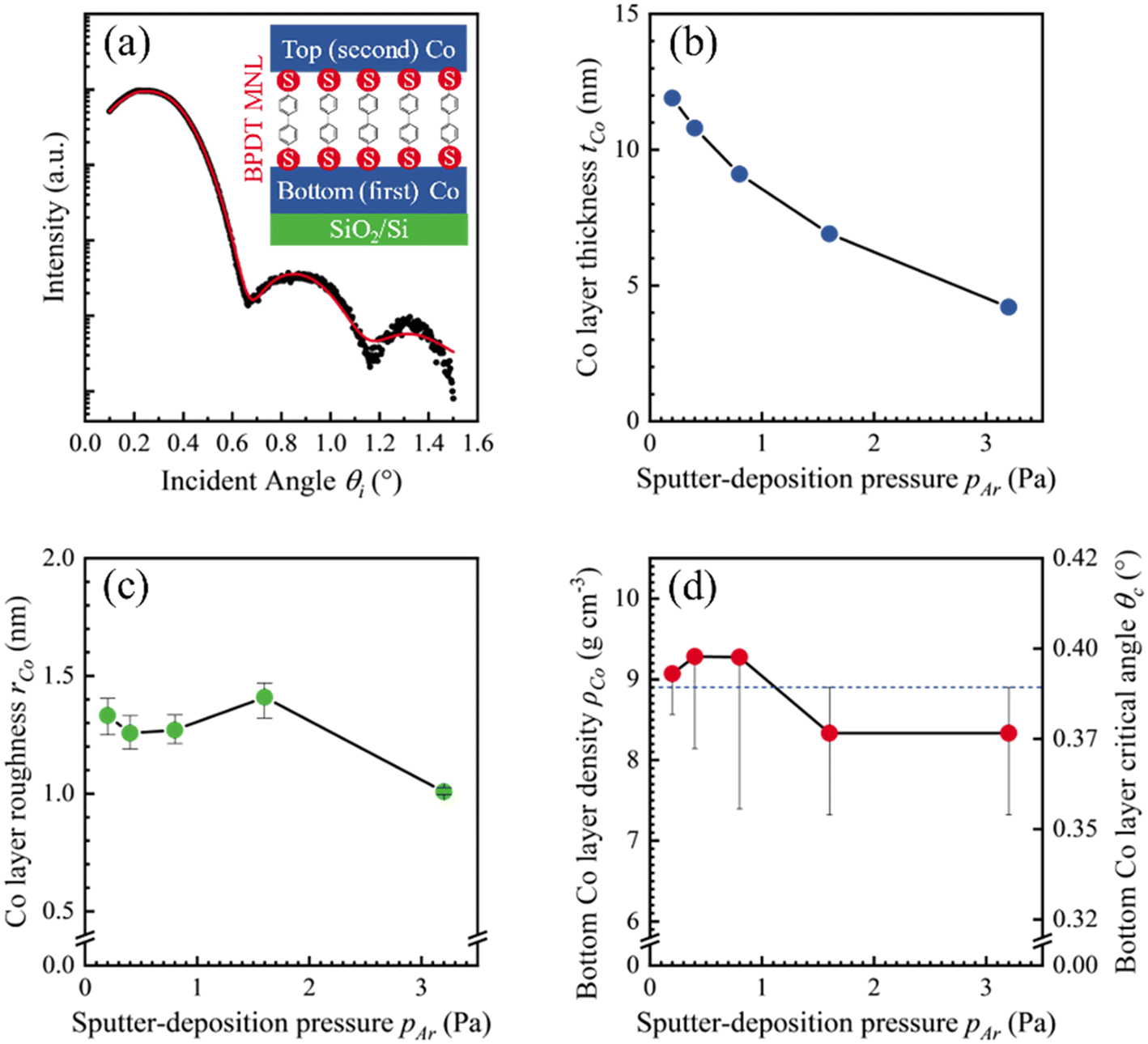 | ||
| Fig. 1 (a) XRR data overlayed with the best fit model (red curve) for a Co film deposited on SiO2/Si at pAr = 0.8 Pa. The inset is a schematic of a Co/BPDT/Co thin film sandwich. The (b) thickness and (c) the Co layer roughness rCo plotted as a function of pAr. The fitting uncertainties in tCo are less than the symbol dimension representing each data point. (d) ρCo (left ordinate) obtained by θc (right ordinate) determined from XRR data plotted as a function of pAr. The horizontal dashed line denotes both ρCo and θc expected for bulk Co. | ||
The Co film deposition rate and time were determined for different Ar pressures in the 0.20 ≤ pAr ≤ 3.2 Pa range. The substrates were placed on an electrically floating holder placed 140 mm from the Co sputter target. The first Co (bottom) layer was sputter deposited using 15 W dc power plasma. For BPDT MNL formation on the first (bottom) Co layer, the Co/SiO2/Si structures were transferred to the load-lock and exposed to BPDT flux from a crucible containing ∼100 mg BPDT powder (95% purity, Aldrich). The load-lock pressure was held above 0.4 Pa during transfer. BPDT molecules were sublimed for 30 minutes at ≲0.3 Pa (ref. 26) and with the crucible temperature at Tsublimation = 45 ± 5 °C. The BPDT/Co/SiO2/Si structures were transferred back to the main chamber for sputter-depositing the Co overlayer on the BPDT MNL. For all Co/MNL/Co sandwiches, the targeted thicknesses of the bottom and top Co layers tCo were 8 nm, and 4 nm, respectively.
Co film thickness and density were determined using Rutherford backscattering spectroscopy (RBS) and X-ray reflectivity (XRR) measurements. RBS data was acquired using a 2 MeV He2+ beam incident at 5° to the surface normal, with the detector placed at a 170° scattering angle, and fit using SIMNRA simulations27,28 of model structures. XRR measurements were carried out in a Rigaku Smartlab diffractometer with Cu Kα radiation, and the data was analyzed using the PANalytical X'Pert Reflectivity software.29 The top Co layer roughness rCo in the Co/MNL/Co sandwiches were measured by tapping-mode atomic force microscopy (AFM) with a Bruker Dimension 3100 instrument, and the data was analyzed with the WSxM software.30
X-ray photoelectron spectroscopy (XPS) was used to study BPDT MNL formation in a Kratos Ultra DLD instrument (<1 × 10⁻⁷ Pa base pressure) equipped with a monochromatic Al Kα source. The pass energy was set to 160 eV for the survey scans and to 20 eV for higher energy resolution scans. Charging-induced shifts were corrected using the Co Fermi edge as the reference, and MultiPak31 software was used for analysis. Raman spectra were obtained in a home-built system with a ∼0.8 μm spot from a ∼0.5 mW 532 nm solid-state laser, and a ∼5.5 cm−1 resolution detector.
Results and discussion
The first Co layer on SiO2/Si
XRR data from Co-covered SiO2/Si(001) substrates were fit with simulated curves from Co/SiO2/Si models assuming homogenous densities and linear gradient interfaces (see Fig. 1a). XRR data analyses show that the nominal Co film thickness tCo monotonically decreased with increasing Ar pressure pAr at which the Co film was sputter-deposited (Fig. 1b). We extracted tCo from Kiessig fringe positions from simulations of model Co/SiO2/Si(001) structures of layers with different values of homogeneous densities. Our simulations also show that the Co layer RMS roughness32 is in the 1.0 ≤ rCo ≤ 1.4 nm range with no correlation with pAr (Fig. 1c). Analyses of the dI/dθi minima associated with the total-external reflection angle θc (see ESI†) showed that the Co film density remained invariant with pAr at ρXRRCo = 8.8 ± 0.6 g cm−3 (Fig. 1d).SIMNRA fits of RBS spectra for Co/SiO2/Si model structures (e.g., see Fig. 2) yield an areal Co film density ACo = 72 × 1015 atoms cm−2. Dividing ACo with tCo obtained from XRR analyses yields a Co film density ρRBSCo = 8.7 ± 0.1 g cm−3, which is within 1% of the density ρXRRCo. Additionally, dividing ACo with ρXRRCo yields tCo = 8.0 ± 0.6 nm, which agrees well with tCo determined from Kiessig fringes by XRR. These results confirm that the extracted values of tCo and ρCo are self-consistent, with no observable changes in ρCo.
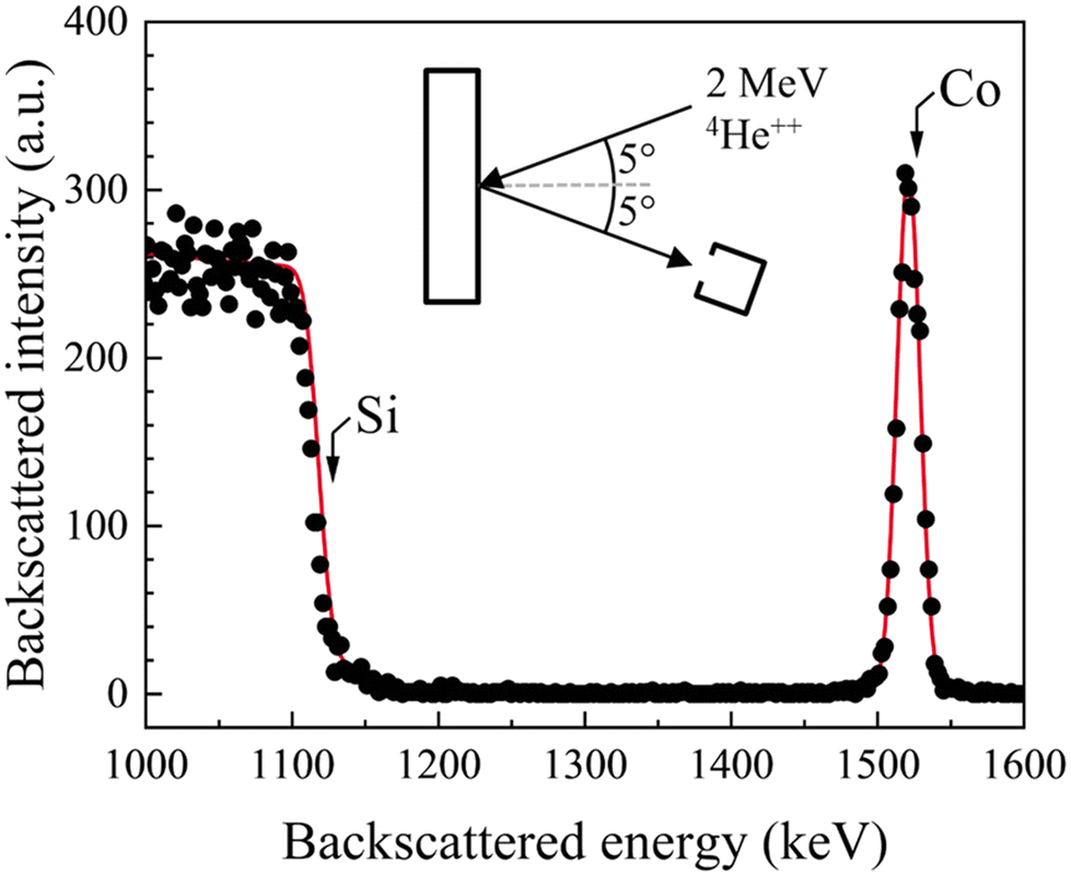 | ||
| Fig. 2 A representative RBS spectrum (points) and the SIMNRA simulation (line) from a Co film deposited at pAr = 0.8 Pa (6 mTorr). | ||
XPS spectra from Co films exposed to BPDT fluxes revealed S 2p core-level peaks33,34 (Fig. 3a). Surprisingly, even as-deposited Co films showed S 2p peaks, albeit of lower intensity. This result indicates inadvertent BPDT exposure during sample residence and exchanges in the load-lock either directly from the sublimation cell or refluxing from the load-lock chamber walls. Given the low BPDT vapor pressure,26 this outcome was unexpected, and underscores the importance of using a shutter to physically isolate the molecular source during hybrid nanocomposites synthesis.
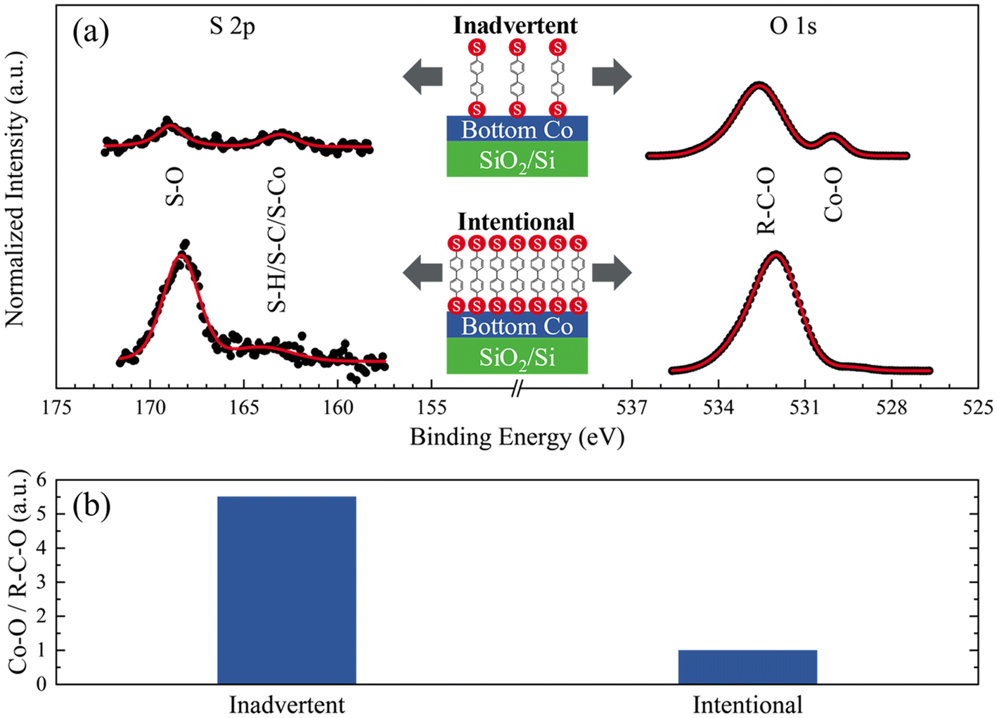 | ||
| Fig. 3 (a) S 2p and O 1s core-level spectra obtained by XPS at a θSD = 45° from Co films with inadvertent (top) and intended (bottom) BPDT exposure. (b) Co–O/R–C–O ratios derived from the O 1s spectra. All intensities are normalized to that of the Co 2p peak. | ||
The O 1s contribution35–37 associated with Co–O bonding is ∼4-fold lower in Co films intentionally exposed to BPDT than in Co films with inadvertent BPDT exposure (Fig. 3b). This result indicates that BPDT MNL formed by intentional sublimation curtails Co oxidation considerably more than BPDT adsorption through inadvertent exposure, suggesting that inadvertent BPDT fluxes in our experiments do not result in continuous BPDT MNLs.
Second Co layer deposition to synthesize Co/BPDT/Co sandwiches
XRR data from Co/BPDT/Co sandwiches with top Co layers deposited at 0.2 ≤ pAr ≤ 3.2 Pa exhibit two differential reflectivity minima (see ESI†) corresponding to θCoc and θSic for 0.2 ≤ pAr ≤ 1.6 Pa. The data could not be fit with differential reflectivity curves generated from Co/BPDT/Co models with discrete layers. The similarity of the X-ray penetration depth and the film thicknesses in these structures confound the combined effects of even small changes in film roughness, thickness and composition, complicating meaningful interpretation.The areal density of the top Co layer AtopCo was determined by fitting RBS data from Co/BPDT/Co sandwiches (Fig. 4a) using tCo = 8.1 nm and ACo = 72 atoms × 1015 cm−2 for the bottom Co layer. These results show that the top Co layer ACo monotonically decreases with increasing pAr (Fig. 4b). Our XRR results indicate that the Co density ρCo for the bottom layer is invariant for 0.2 ≤ pAr ≤ 3.2 Pa. If ρCo is similarly invariant for the top Co layer, and ρtopCo = ρbottomCo = 8.8 g cm−3, the top-layer Co thickness ttopCo = ρRBSCo/AtopCo is estimated to be in the 3.1 ≤ ttopCo ≤ 4.7 nm range. The mean ttopCo = 3.9 ± 0.7 nm, which is close to the intended ttopCo = 4 nm.
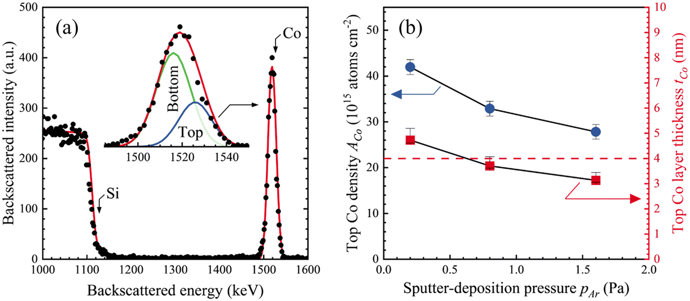 | ||
| Fig. 4 (a) The Co peak from a representative RBS spectrum fit with SIMNRA simulations (line) from a Co/BPDT/Co sandwich with the top Co layer deposited at pAr = 0.8 Pa. Inset shows a magnified view of the Co peak, with the top and bottom Co layer contributions from simulations. (b) Areal density and thickness of the top Co nanolayer plotted versus pAr. | ||
AFM measurements of the top Co layer in the Co/BPDT/Co sandwiches (Fig. 5a) show a monotonic increase in root-mean-square roughness rCo with pAr (Fig. 5b). Since the tbottomCo values are similar (within ±1.6 nm) with only a slight decrease with pAr, the observed rCo increase is clearly not a film thickness effect. The pAr–rCo correlation seen in the top Co layer is absent in the bottom Co layer, as described earlier in section 3.1, and plotted in Fig. 5b for comparison. We thus infer that the higher roughness of the top Co layer in Co/BPDT/Co structures is due to the presence of the underlying BPDT MNL.
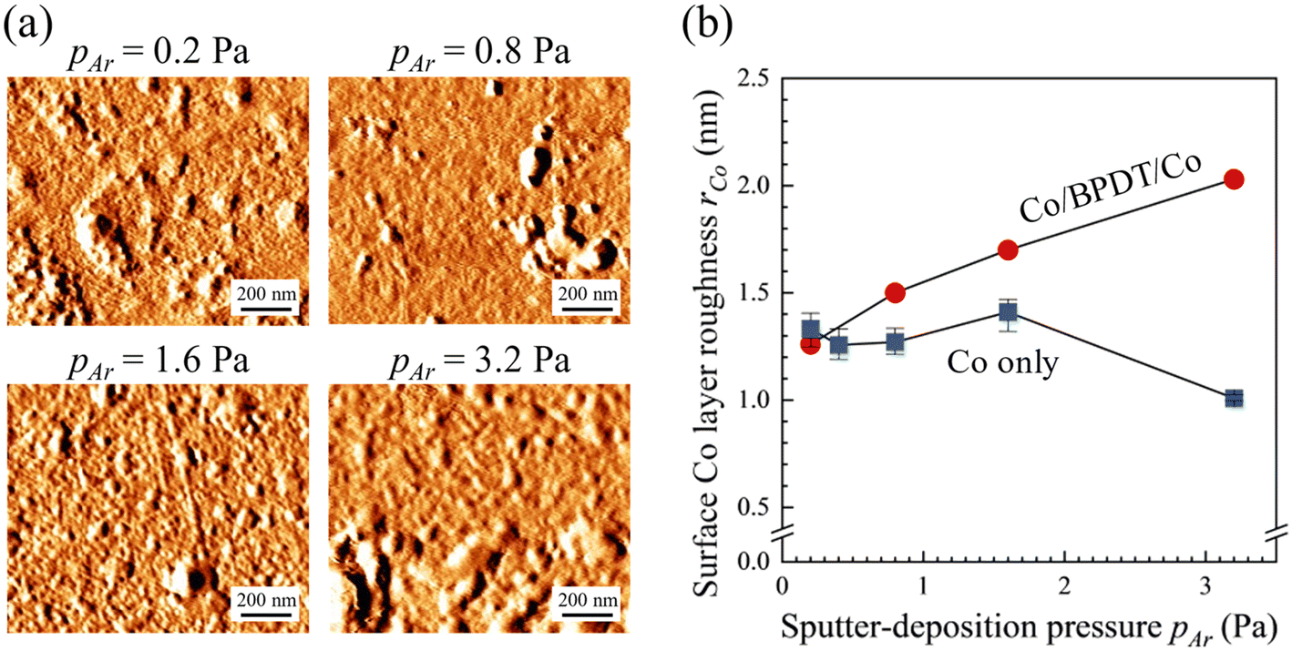 | ||
| Fig. 5 (a) AFM images from Co/BPDT/Co sandwiches for the top Co layer deposited at different pAr. (b) Top Co layer roughness in Co/BPDT/Co sandwiches (circles) and the bottom Co layer roughness in Co/SiO2/Si(001) structures (squares) plotted versus pAr. Roughness uncertainty is indicated by symbol size or error bar bounds, whichever is greater. | ||
Higher frequency of gas-phase collisions expected with increasing pAr could promote higher roughness due to lowered adatom mobility resulting from lower average energy of sputtered species impinging on the surface at shallower angles. However, since this effect is not seen for the bottom Co layer deposited on SiO2, we attribute the pAr–rCo correlation in the top Co layer to the presence of the BPDT MNL. It appears that the presence of an MNL accentuates the self-shadowing from low mobility of metal adatoms expected at higher pAr by virtue of the initial roughness caused by the BPDT layer. Thus, higher pAr leads to roughening for the top Co layer but not the bottom one grown on flat SiO2. These observations suggest that the nature and extent of the MNL influence on the inorganic overlayer morphology are likely to be dependent on MNL chemistry and morphology.
XPS spectra recorded from Co/BPDT/Co sandwiches (see Fig. 6, and ESI†) indicate a correlation between Co oxidation and pAr, and corroborate BPDT adsorption on the top Co layer surface due to unintentional BPDT exposure discussed earlier. Co 2p peaks contain metallic Co0 as well as oxidized Co+2 and Co+3 contributions38–40 (Fig. 6a). Assigning these non-zero oxidation states specifically to either Co–O or Co–S bonds is precluded by overlaps in Co–S and Co–O signatures. The normalized oxidized/metallic Co peak ratio (Fig. 6b) does not exhibit any discernable trend with pAr.
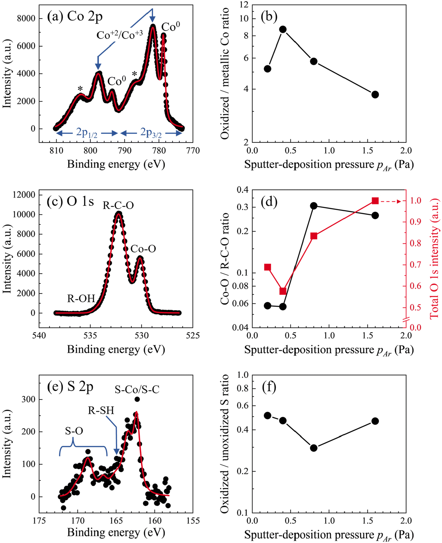 | ||
| Fig. 6 (a) Co 2p, (c) O 1s and (e) S 2p spectra from Co/BPDT/Co nanolayers at θSD = 60°. In the Co 2p band, * represents Co satellite peaks. Semi-log plots of sub-band intensity ratios from (b) Co 2p, (d) O 1s and (f) S 2p plotted as a function of pAr. The total O 1s band intensity is also shown on a linear scale (d, right axis). Detailed sub-band fittings are given in ESI.† | ||
Intensities of both the O 1s peak (Fig. 6c) and the O–Co sub-band35–37 (Fig. 6d) increase with pAr, indicating that higher pAr is associated with a greater degree of oxidation of the top Co layer. Viewing this result alongside the pAr–rCo correlation for the top Co layer suggests a connection between Co layer roughness and the degree of Co oxidation to Co+2 or Co+3 states. The S 2p peak from adventitious BPDT are comprised of sub-bands from –SH, S–C, S–Co, and S–O moieties33,34 (Fig. 6e). The sub-band in the 162–164 eV regime is labeled as S–Co/S–C because the S–Co and S–C states were indistinguishable in our measurements limited by ∼1 eV spectral resolution in our measurements. The high-binding energy sub-bands from a small fraction of S–O bonds are not captured in the O 1s spectra because of vast differences in the relative intensities of O 1s and S 2p peaks (see Fig. 6c & e and survey spectra in ESI†). The oxidized/unoxidized S (Fig. 6f) ratio does not exhibit any discernable trend with pAr.
Variable take-off angle XPS measurements show that the C 1s peak attenuates the least and Co 2p peaks attenuates the most with increasing surface-to-detector angle θSD (Fig. 7a). These results indicate41 that a C layer covers the top Co layer, with oxygen and sulfur straddled in between. For all θSD, the Co 2p and O 1s intensity attenuation trends with pAr appear to be correlated (Fig. 7b), consistent with increased Co oxidation at high pAr. The C 1s band intensity attenuation is insensitive to pAr, and the S 2p band mimics this for pAr < 0.4 Pa. At higher pAr, the S 2p relative intensity is distinctly lower than that of O 1s. These results suggest that Co oxidation decreases with decreasing Co–S linkages at the Co/BPDT interface.
 | ||
| Fig. 7 Normalized core-level peak intensities from XPS plotted versus (a) surface-to-detector angle θSD, and (b) sputter-deposition pressure pAr. For each element, the intensities are normalized to that for θSD = 80° (in a), and normalized to the maximum intensity (in b) for each θSD, namely, 80° (diamonds), 75° (triangles), 60° (circles), and 40° (squares). | ||
Raman spectra from Co/BPDT/Co sandwiches (Fig. 8) exhibit the following signatures of BPDT:24,42–44 C![[double bond, length as m-dash]](https://www.rsc.org/images/entities/char_e001.gif) C stretching (1590 cm−1), C–C stretching (1288 cm−1) between, and C–H bending (1201 cm−1) within, the aromatic rings, and S–C stretching (1078 cm−1). The lack of an observable peak at 376.6 cm−1 indicates –SH moieties did not react with each other to form disulfides. These suggest that the sputter-deposition of a Co overlayer does not destroy the BPDT structure, consistent with MNLs being resilient to <∼10 eV projectiles.45
C stretching (1590 cm−1), C–C stretching (1288 cm−1) between, and C–H bending (1201 cm−1) within, the aromatic rings, and S–C stretching (1078 cm−1). The lack of an observable peak at 376.6 cm−1 indicates –SH moieties did not react with each other to form disulfides. These suggest that the sputter-deposition of a Co overlayer does not destroy the BPDT structure, consistent with MNLs being resilient to <∼10 eV projectiles.45
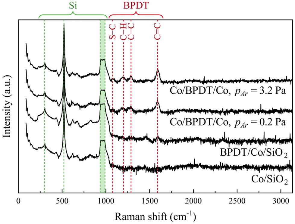 | ||
| Fig. 8 Raman spectra from the Co layer before and after BPDT exposure, and from Co/BPDT/Co sandwiches plotted on a semi-log plot. For the bottom Co layer pAr = 0.8. | ||
Conclusions
Results of our studies on nanolayered Co/BPDT/Co sandwiches provide valuable insights for the design and synthesis of nanolayered hybrid inorganic–organic laminates. In particular, our results reveal MNL-induced roughening of Co overlayers, which increases with the Ar pressure pAr during sputter deposition. It appears that the MNL accentuates self-shadowing of low mobility Co adatoms. This effect is more pronounced at higher pAr wherein increased gas-phase collisions result in low-energy Co fluxes impinging on the surface at shallow angles. Furthermore, MNL-induced Co layer roughening is correlated with a higher degree of Co oxidation, pointing to the importance of the pAr in controlling both the morphology and the chemistry of sputtered metal films on the MNL-covered surfaces. These results also suggest that the nature and extent of MNL-induced pAr-oxidation and pAr-roughness correlations are likely to be related to the MNL chemistry and morphology. This knowledge should be important for the design and synthesis of inorganic–organic nanolaminates with emergent properties, e.g., transparent electrical conductors, flexible thermoelectrics, and smart materials with mechanical bandgaps.Conflicts of interest
There are no conflicts to declare.Acknowledgements
We gratefully acknowledge funding from the US National Science Foundation through the CMMI 2135725 grant, the Swedish Government Strategic Research Area in Materials Science on Advanced Functional Materials Grant SFO-Mat-LiU No. 2009 00971, the Knut and Alice Wallenberg foundation through the Wallenberg Academy Fellows Grant KAW-2020.0196 and Wallenberg Academy Scholar Grant KAW-2019.0290, and the Swedish Research Council through the VR 2021-03826 grant.References
- G. Ramanath, C. Rowe, G. Sharma, V. Venkataramani, J. G. Alauzun, S. Ravishankar, P. Keblinski, D. G. Sangiovanni, P. Eklund and H. Pedersen, Appl. Phys. Lett., 2023, 122, 260502 CrossRef CAS.
- . International Roadmap for Devices and Systems (IRDS™) 2022 Edition, More Moore, https://irds.ieee.org/editions/2022, 2022.
- C. Joachim, J. K. Gimzewski and A. Aviram, Nature, 2000, 408, 541–548 CrossRef CAS PubMed.
- C. Wan, X. Gu, F. Dang, T. Itoh, Y. Wang, H. Sasaki, M. Kondo, K. Koga, K. Yabuki, G. J. Snyder, R. Yang and K. Koumoto, Nat. Mater., 2015, 14, 622–627 CrossRef CAS PubMed.
- J.-P. Niemelä, A. Philip, N. Rohbeck, M. Karppinen, J. Michler and I. Utke, ACS Appl. Nano Mater., 2021, 4, 1692–1701 CrossRef.
- S. K. Arya, P. R. Solanki, M. Datta and B. D. Malhotra, Biosens. Bioelectron., 2009, 24, 2810–2817 CrossRef CAS PubMed.
- B. Yoon, B. H. Lee and S. M. George, J. Phys. Chem. C, 2012, 116, 24784–24791 CrossRef CAS.
- D. D. Gandhi, M. Lane, Y. Zhou, A. P. Singh, S. Nayak, U. Tisch, M. Eizenberg and G. Ramanath, Nature, 2007, 447, 299–302 CrossRef CAS PubMed.
- M. Kwan, M. Braccini, M. W. Lane and G. Ramanath, Nat. Commun., 2018, 9, 5249 CrossRef CAS PubMed.
- P. J. O'Brien, S. Shenogin, J. X. Liu, P. K. Chow, D. Laurencin, P. H. Mutin, M. Yamaguchi, P. Keblinski and G. Ramanath, Nat. Mater., 2013, 12, 118–122 CrossRef PubMed.
- T. Cardinal, Devender, T. Borca-Tasciuc and G. Ramanath, ACS Appl. Mater. Interfaces, 2016, 8, 4275–4279 CrossRef CAS PubMed.
- U. Helmersson, S. Todorova, S. A. Barnett, J. E. Sundgren, L. C. Markert and J. E. Greene, J. Appl. Phys., 1987, 62, 481–484 CrossRef CAS.
- R. Khadka, G. Ramanath and P. Keblinski, Sci. Rep., 2022, 12, 10788 CrossRef CAS PubMed.
- B. H. Lee, B. Yoon, V. R. Anderson and S. M. George, J. Phys. Chem. C, 2012, 116, 3250–3257 CrossRef CAS.
- A. Tanskanen and M. Karppinen, Dalton Trans., 2015, 44, 19194–19199 RSC.
- J. Liu, B. Yoon, E. Kuhlmann, M. Tian, J. Zhu, S. M. George, Y.-C. Lee and R. Yang, Nano Lett., 2013, 13, 5594–5599 CrossRef CAS PubMed.
- J. Multia and M. Karppinen, Adv. Mater. Interfaces, 2022, 9, 2200210 CrossRef CAS.
- S. M. George, A. A. Dameron and B. Yoon, Acc. Chem. Res., 2009, 42, 498–508 CrossRef CAS PubMed.
- M. A. D. Millone, H. Hamoudi, L. Rodríguez, A. Rubert, G. A. Benítez, M. E. Vela, R. C. Salvarezza, J. E. Gayone, E. A. Sánchez, O. Grizzi, C. Dablemont and V. A. Esaulov, Langmuir, 2009, 25, 12945–12953 CrossRef PubMed.
- J. F. Kang, A. Ulman, S. Liao, R. Jordan, G. Yang and G.-y. Liu, Langmuir, 2000, 17, 95–106 CrossRef.
- A. Niklewski, W. Azzam, T. Strunskus, R. A. Fischer and C. Wöll, Langmuir, 2004, 20, 8620–8624 CrossRef CAS PubMed.
- J.-P. Niemelä, A. J. Karttunen and M. Karppinen, J. Mater. Chem. C, 2015, 3, 10349–10361 RSC.
- Y. Du, J. Xu, B. Paul and P. Eklund, Appl. Mater. Today, 2018, 12, 366–388 CrossRef.
- U. Weckenmann, S. Mittler, K. Naumann and R. A. Fischer, Langmuir, 2002, 18, 5479–5486 CrossRef CAS.
- A. le Febvrier, L. Landälv, T. Liersch, D. Sandmark, P. Sandström and P. Eklund, Vacuum, 2021, 187, 110137 CrossRef CAS.
- J. Gaube, Ber. Bunsen-Ges., 1985, 89, 352–352 CrossRef.
- M. Mayer, Max-Planck-Institut für Plasmaphysik, 1997 Search PubMed , Report IPP 9/113.
- M. Mayer, AIP Conf. Proc., 1999, 475, 541–544 CrossRef CAS.
- L. G. Parratt, Phys. Rev., 1954, 95, 359–369 CrossRef.
- I. Horcas, R. Fernández, J. M. Gómez-Rodríguez, J. Colchero, J. Gómez-Herrero and A. M. Baro, Rev. Sci. Instrum., 2007, 78, 013705 CrossRef CAS PubMed.
- MultiPak, Version 9.6.1.7, Ulvac-phi, Inc., 2015 Search PubMed.
- J. Stettner, L. Schwalowsky, O. H. Seeck, M. Tolan, W. Press, C. Schwarz and H. V. Känel, Phys. Rev. B: Condens. Matter Mater. Phys., 1996, 53, 1398–1412 CrossRef CAS PubMed.
- S. A. Best, P. Brant, R. D. Feltham, T. B. Rauchfuss, D. M. Roundhill and R. A. Walton, ChemInform, 1977, 8 Search PubMed.
- X. Ma, W. Zhang, Y. Deng, C. Zhong, W. Hu and X. Han, Nanoscale, 2018, 10, 4816–4824 RSC.
- J. Yang, H. Liu, W. N. Martens and R. L. Frost, J. Phys. Chem. C, 2010, 114, 111–119 CrossRef CAS.
- J.-C. Dupin, D. Gonbeau, P. Vinatier and A. Levasseur, Phys. Chem. Chem. Phys., 2000, 2, 1319–1324 RSC.
- S. Chenakin and N. Kruse, Appl. Surf. Sci., 2020, 515, 146041 CrossRef CAS.
- M. C. Biesinger, B. P. Payne, A. P. Grosvenor, L. W. M. Lau, A. R. Gerson and R. S. C. Smart, Appl. Surf. Sci., 2011, 257, 2717–2730 CrossRef CAS.
- A. Foelske and H.-H. Strehblow, Surf. Interface Anal., 2000, 29, 548–555 CrossRef CAS.
- L. Liu, Z. Jiang, L. Fang, H. Xu, H. Zhang, X. Gu and Y. Wang, ACS Appl. Mater. Interfaces, 2017, 9, 27736–27744 CrossRef CAS PubMed.
- M. Kwan, T. Cardinal, P. H. Mutin and G. Ramanath, Appl. Phys. Lett., 2016, 108, 191607 CrossRef.
- Y. R. Lee, M. S. Kim and C. H. Kwon, Bull. Korean Chem. Soc., 2013, 34, 470–474 CrossRef CAS.
- S. W. Joo, S. W. Han and K. Kim, J. Phys. Chem. B, 1999, 103, 10831–10837 CrossRef CAS.
- E. O. Ganbold and S. W. Joo, Bull. Korean Chem. Soc., 2015, 36, 244–249 CrossRef.
- S. A. Miller, H. Luo, S. J. Pachuta and R. G. Cooks, Science, 1997, 275, 1447–1450 CrossRef CAS.
Footnote |
| † Electronic supplementary information (ESI) available. See DOI: https://doi.org/10.1039/d3dt01910a |
| This journal is © The Royal Society of Chemistry 2024 |