
 Open Access Article
 This Open Access Article is licensed under a
 Creative Commons Attribution 3.0 Unported Licence
GLAS: an open-source easily expandable Git-based scheduling architecture for integral lab automation†
Jean-Charles
Cousty‡
a,
Tanguy
Cavagna‡
 b,
Alec
Schmidt‡
b,
Edy
Mariano
a,
Keyan
Villat
a,
Florian
de Nanteuil
c and
Pascal
Miéville
*a
b,
Alec
Schmidt‡
b,
Edy
Mariano
a,
Keyan
Villat
a,
Florian
de Nanteuil
c and
Pascal
Miéville
*a
aSwiss Cat+ West Hub, Ecole Polytechnique Fédérale de Lausanne EPFL, 1015 Lausanne, Switzerland. E-mail: pascal.mieville@epfl.ch
bDépartement Informatique et Systèmes de Communication, Haute Ecole du Paysage, d'Ingénierie et d'Architecture HEPIA, 1202 Geneva, Switzerland
cDSM-Firmenich, 1217 Meyrin, Switzerland
First published on 8th November 2024
Abstract
This paper presents GLAS (Git-based Lab Automated Scheduler or Get Lab Automation Simplified), an open-source, robust, and highly expandable Git-based architecture designed for laboratory automation. GLAS can be deployed in both partially and fully automated experimental science laboratories, enabling the development of a multi-layer scheduling system while maintaining a systematic architecture grounded in a Git repository. We demonstrate the applicability of GLAS through case studies from the Swiss Cat+ automated chemistry laboratory, showcasing its versatility and potential for widespread applicability in various laboratory automation contexts. By offering an open-source scheduling environment, our aim is to foster the development of accessible and adaptable laboratory automation solutions within the scientific community.
1 Introduction
As evidenced by numerous research papers,1–8 laboratory automation is becoming a central aspect of modern chemistry and more generally of experimental and digital sciences. Automation enables the generation of data at a faster rate,9 reduces the likelihood of human error, and introduces automatic sample control sequences, thereby enhancing the systematicity of data acquisition.10 Automation is also less prone than humans to selection bias and frustration,11,12 which will help to improve the variety of available data, particularly in the context of negative data.13,14 The data quality and high-throughput potential of laboratory automation make it an essential component of the current closed-loop optimization15 and data-driven chemistry16–18 or formulation19,20 fast development. Automating a laboratory involves both the hardware constituted by scientific equipment and connecting robots,21 as well as the IT system management, including the data management system and the task management.22,23In their respective studies, Flores-Leonar et al.24 and Coley et al.11 identified the essential elements of the task management chain in automated chemistry laboratories through a platform-based approach. Bai et al.25 provided a clear schematic representation of this platform-based approach. The aforementioned schematic representation is reproduced for the sake of simplicity and adapted for a large and entire laboratory automation case, as illustrated in Fig. 1. The primary distinctions between the original Bai et al. scheme and the proposed modification pertain to the incorporation of additional entities essential to the operation of large-scale systems, such as the logistics laboratory management (chemicals ERP, solvent and waste management) module. This module is complemented by a dedicated data processor (processor) unit, which oversees the systematic processing of scientific equipment-generated data and facilitates their potential utilization for structural elucidation26–29 and chemometric analysis.30–33 A further modification to the original scheme is the incorporation of sample transfer and robotics into the Executor section. As previously described by Thurow and Junginger6,21 and also discussed by Wolf et al.,34 when considering a complete laboratory automation system, it is likely that the system will have to be open and decentralized. This requires the combination of different types of robotics and automation, including mobile platforms, SCARA and 6-axis arms, and fluidics.35,36
 | ||
| Fig. 1 Platform based laboratory automation scheme, adapted and modified from Bai et al.,25 illustrates the fundamental components of a comprehensive laboratory automation system. The principal distinctions between the original scheme and the revised one are the incorporation of a logistician actor for the ERP, consumable and waste management system, as well as the introduction of a processor dedicated to processing data and analyzing the results in a systematic and controlled manner. This is necessary because the diversity of instruments in a completely automated laboratory makes it challenging to obtain structured results that can be further utilized in data sciences. The incorporation of such processors facilitates the standardization of data formats, structures, and quality prior to their incorporation into ML models. The final modification pertains to the incorporation of a sample transfer and robotics tool to facilitate the transfer of samples over extended distances. Furthermore, automated actions may be applied directly to the sample, as it is the case in fluidics. | ||
The present paper concentrates on the segment of the automation process that commences with the Coordinator and concludes with the Executor. In particular, it examines the scheduling aspect of the process, which is represented by the scheduler in the Coordinator block. Furthermore, the structure of the process is considered, including the Equipment Application Programming Interface (API) located in the Executor. The scheduling of tasks is of paramount importance in a global automation system, as it converts the workflows into a sequence of physical operations, orchestrates the tasks in the appropriate order and at the optimal timing, taking into account the status of the different equipment and the completion of previous tasks. For this, a novel multilayered Git-based37 open-source laboratory automation scheduling architecture, designated GLAS for Git-based Lab Automation Scheduler or eventually Get Lab Automation Simplified is presented here. The global lab scheduling is based on a multilayered and repetitive container38 architecture, which is coded in a Git environment. The system has been designed to be applicable in large, entirely automated laboratories, which present a significant variety of scientific and logistic equipment. Furthermore, it can also be implemented into smaller and localized laboratory automation projects that combine a limited number of scientific equipment and sample manipulators.
The primary advantage of this architectural approach is its adaptability, which enables the automation and the communication between a wide range of scientific equipment in a structured manner. This encompasses synthesis stations, sampling tools, analytical equipment, laboratory robotics, and all connecting robotics. Each layer is dedicated to a specific level of operational control. The system can be designed to control a specific group of tasks, such as all transfer robots, or it can be optimized to work with automation controllers, such as those produced by Beckhoff, Siemens, or Arduinos. Alternatively, it can be employed to integrate external vendor scientific equipment or a group of scientific equipment with its own controlling software, open-source external controllers such as Chemspyd39 and proprietary sample schedulers (e.g., Agilent Sample Scheduler from Open Lab CDS). A second advantage is that the Main Laboratory Scheduler is an independent layer in the GLAS architecture, allowing for adaptation to any laboratory requirement or habit. Scheduling can be executed in a linear manner, adhering to the First-In First-Out (FIFO) principle.40 Alternatively, it can be more complex, with optimized time allocation of instruments to minimize the overall time required to complete experimental procedures. In this context, the GLAS architecture is inherently parallel, as any groups of instruments can be controlled independently and can therefore be used to extend FIFO schedulers to a certain degree of parallelization. To illustrate this possibility, we present the use of a REST API-based scheduler as a main laboratory in our Swiss Cat+ laboratory. However, we emphasize that this is merely one potential option and that the selection of the Main Laboratory Scheduler, despite being pivotal in terms of scheduling performance, is independent of the use of a GLAS architecture. A third advantage of this architectural approach is its systematicity, which is enabled by the container approach. Every set of functions and workflows, can be tailored to a specific equipment or groups of equipment, is encoded into a conservative architecture and can be called upon by the upper scheduling layer with higher-level commands. Finally, the system's Git-based architecture allows for rapid deployment in a new laboratory setting, with the capacity to encompass the entire laboratory and to incorporate new groups of equipment and functions with minimal effort. This is achieved by only developing the newly needed layer and referencing it in the upper one.
2 The GLAS architecture for complete laboratory automation scheduling
The GLAS architecture, as illustrated in Fig. 2 below (for a hypothetical generic case of 3 layers and 3 groups of equipment with specific sub-groups), is intended to occur within the segment of Fig. 1 that extends from the Coordinator Tasks scheduler to the APIs in the Executor. The GLAS architecture is structured in a multilayered configuration, with the Main Laboratory Scheduler situated in the Coordinator level, followed by a variable number of Git-based Group Sub-Schedulers. The number of groups, sub-groups, and layers of sub-schedulers is contingent upon the number and type of laboratory equipment or computer systems in use and the intricacy of the workflows involving disparate equipment. | ||
| Fig. 2 Schematized multilayered GLAS scheduling architecture for a hypothetical laboratory containing 11 different equipment items, with the Main Laboratory Scheduler located at the top (Coordinator level) and directly connected to the experiment coder & decoder tool at receptionist level (this tool will be presented in detail in a separate publication). From the Main Laboratory Scheduler, all Git-based Sub-Schedulers components are connected and organized in groups, with each group corresponding to the functionality of the equipment item represented here by the associated API. The architecture is composed of as many layers as necessary to ensure a smooth functioning and to place the appropriate level of complexity at the closest level of the equipment. | ||
A fundamental tenet of this architectural framework is to situate complexity in a minimal and proximate manner relative to the equipment. This can be readily grasped by traversing the hierarchy from the lowest to the highest level. The Base Methods (BM), which are defined in terms of specific variables, are entirely defined at the level of the equipment (Executor) and can be called through the dedicated Application Programming Interface (API). In this context, a BM is defined as a series of standardized operations that are controlled locally by the equipment control software.
For instance, it could be an HPLC separation method, a synthesis unitary operation such as filtration or heating, or a robot simple task such as moving a plate from point A to B. It is possible for a single piece of equipment to have multiple BMs. At the next level (level 3 sub-groups in Fig. 2), the BMs are represented as simple line commands with the appropriate variables. They can be grouped into more complex workflows (method level 3, M3) to combine systematically different actions of grouped equipment. This approach facilitates the systematic organization of actions and ensures operational integrity. In the GLAS architecture, BMs and low-level methods M3 are specified in the configuration of nodes (cf.Chart 1, snippet code 1). Nodes may be either instruments of the Executor level or level 3 sub-schedulers associated with a dedicated group of instruments. At the upper level (level 2), BMs or M3s are called through command lines again with the appropriate variables and parameters and are combined in higher-level methods M2 defined as workflows (cf.Chart 1, snippet code 2).
 | ||
| Chart 1 Two examples of configurations: one for a node (left) and one for a workflow (right). Both are utilized by the Robot Sub-Scheduler, which is presented in the Experimental use cases section 1 below. A node represents an Executor layer entity with parameterized values and basic methods that are invoked within a workflow as steps. The code snippet 1 corresponds to a specific implementation of a 6-axis Universal Robot associated with the NMR spectrometer. A workflow is a higher-level method defined at level 2 and above schedulers (see Fig. 3). Code snippet 2 is a workflow defined in the level 2 sub-scheduler named Robot Sub-Scheduler defining the transfer of samples from a group of equipment named OmniFire (omni) to the NMR spectrometer (nmr). The local sample transfer is conducted using two six-axis Universal Robots UR5e, situated at the OmniFire level (ur5-omni) and NMR (ur5-nmr), respectively. The long-range sample transfer is accomplished via the Swiss Cat+ 2D drone swarm system, a locally developed swarm of mini-mobile robots operated through its Fleet Manager developed in ROS2 (Fleet-Manager). | ||
At the highest level (Coordinator, level 1), generic task lists (e.g., JSON) containing the requisite BM, M3, and M2 with their respective syntax and variables are received by the Main Laboratory Scheduler from the Experiment coder and decoder tool (which will be presented in a separate publication). Subsequently, the Main Laboratory Scheduler transmits the pertinent tasks through POST commands with data included in their bodies to the level-2 sub-scheduler REST API (see below for details). Thereupon, the sequence of instructions is executed in its entirety through the various nodes of the workflow, with the pertinent M and BM being carried out with regard to each specific experiment.
The Basic Methods (BMs) are therefore executed on the instruments in accordance with the specified arguments. The sequence of tasks, workflows, methods and nodes, as well as the different scheduling functions with respect to the different GLAS architecture levels, is presented in Fig. 3. This is a generic example that encompasses an arbitrary number of methods, layers, and variables per method, and it should be representative of the majority of cases. Two comprehensive examples are provided below in the experimental use case sections.
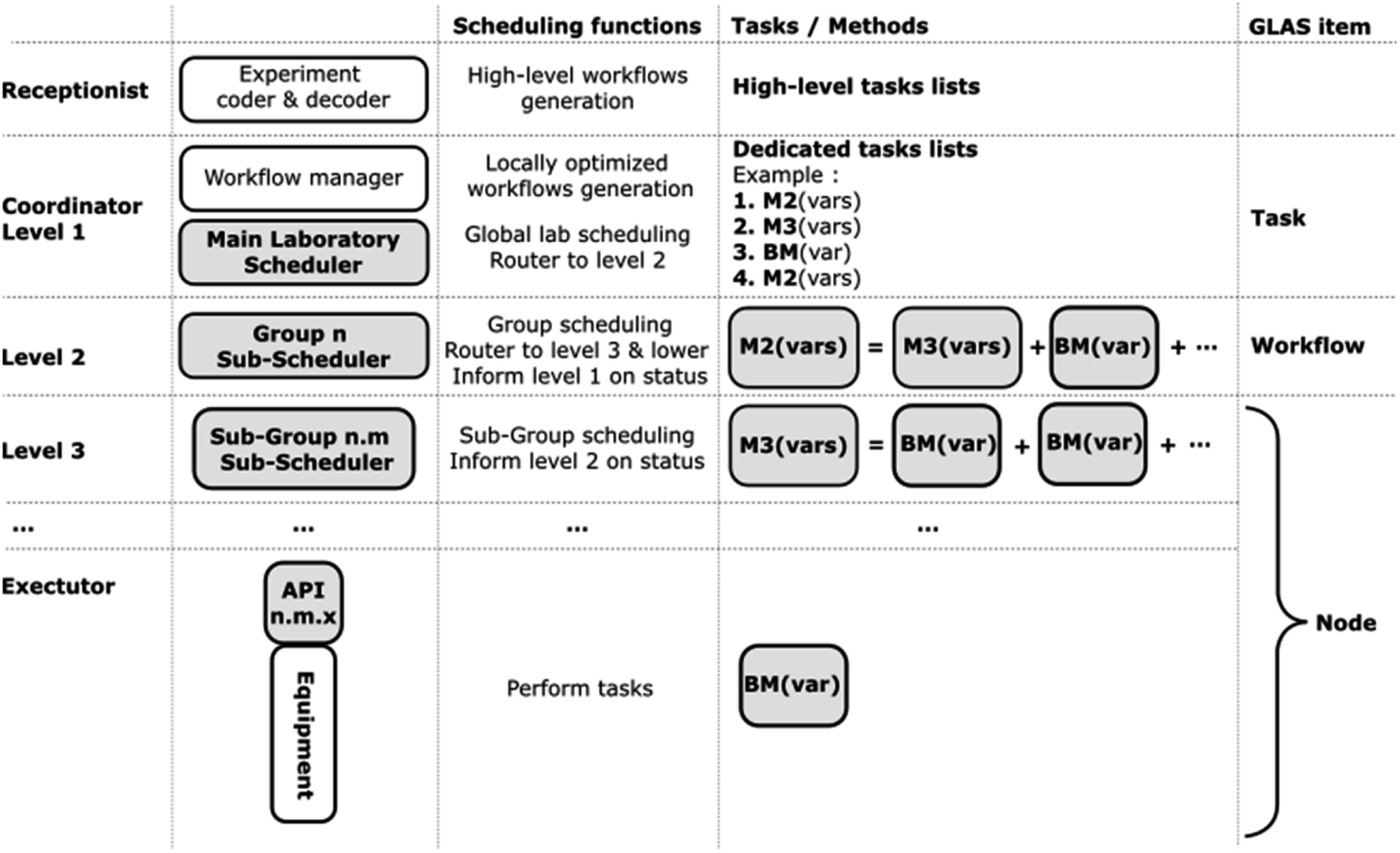 | ||
| Fig. 3 Detailed GLAS architecture, as previously defined in Fig. 2. The first column outlines the levels, the second column provides a general description of the main scheduling elements, and the third column offers a schematic description of the Basic Methods (BM), Methods (M), and task lists organization. Finally, the last column defines the GLAS items corresponding to the previously described elements. | ||
2.1 Execution sequence control
As previously stated, the GLAS architecture is not specific to a particular Main Laboratory Scheduler type. In contrast, the latter constitutes a discrete layer that can be tailored to align with the particular requirements of any given laboratory. This being established, one of the key advantages of the GLAS architecture is its ability to facilitate the parallelization of tasks within a given sub-scheduler, which is associated with a specific set of equipment, as well as between different sub-schedulers. The nodes are executed in a First-In, First-Out (FIFO) at the task level, with nodes being immediately processed in the order in which they become available. In certain cases, contingent on the architectural design (multithreaded, as exemplified in the OmiFire use case 2) and the associated hardware accessibility, multiple instances of a node may be operational concurrently. For example, the Fleet Manager node in the Robot Sub-Scheduler (use case 1) may be one such instance, as it comprises multiple sub-instruments (mobile robots), and is therefore immediately available as soon as one of them is available. The number of parallel tasks that can be controlled is constrained only by the computing power of the laboratory architecture and the availability of the requested workflow. Consequently, even in the event of the utilization of a basic FIFO-based Main Lab Scheduler, GLAS enables the attainment of a substantial degree of operation parallelization. An experimental example of task execution time is provided in Experimental use case 1 below. Further study will present more detailed results regarding parallelization strategies in the context of laboratory automation.2.2 Installation and use
One of the fundamental characteristics of GLAS is its capacity for expansion and customization, enabling alignment with the specific requirements of the user. Moreover, it is possible to integrate any existing equipment control flow with a minimum of complexity. GLAS is designed with a highly expandable architecture that enables the implementation of any communication scheme or behavior when running tasks. This includes the initiation of HTTP requests or low-level communication via serial or DLL interfaces. GLAS is consistently based on an open-source Git architecture written in Python, which underscores its collaborative aspect. The Git system allows new laboratories to develop their implementation of GLAS with minimal effort and at no cost by importing the Git package directly. Git is a versioning software that enables the safe development of code and the saving of files to a repository, typically in the cloud (e.g., GitHub), facilitating collaboration with other developers. In the case of GLAS, it has been developed in a way that allows for seamless integration into a project as a submodule. This enables the continuous development of GLAS while maintaining the ability to utilize the imported version without the necessity of updating (pull) to obtain the latest GLAS version. All pertinent documentation and installation instructions are readily available on the GLAS wiki.41 In order to adapt GLAS to any laboratory layout, it is necessary to include certain minimal required information in the configurations. This information includes an ID as a string, a name for the nodes, as well as a name and steps as node IDs for the workflows. The following code snippets (Chart 1) illustrate possible types of nodes and workflows. In these examples, optional arguments may be provided through the use of the “args” key for a node.Regarding the tasks, GLAS employs a REpresentational State Transfer REST-API42 to receive new tasks with optional arguments, thereby enabling for the addition of specific information to be utilized during the execution. The submission of new tasks is accomplished via the POST method at the following URL: https://<glas-url>/task. The JSON body must adhere to the following structure (Table 1):
| Field | Type | Description | Required |
|---|---|---|---|
| workflow_name | String | The name of the workflow to execute | Yes |
| args | Dict | The arguments given to the task | No |
In GLAS, a task is a self-managed entity that runs as an isolated thread. The task is responsible for validating node execution and handling errors without interrupting the execution of the scheduler. This behavior ensures that access and control over the scheduler is maintained, allowing different clients to retrieve system health diagnostics to perform maintenance if necessary. At the node level, fault management essentially consists of reporting the status of the associated equipment after a BM has been executed. Errors are defined within the BM, are specific to each device and can have different forms (string, code…). They are converted to an integer in the node. A successful BM returns a 0 and any failure corresponds to a non 0. At the scheduler level, the error management must control the execution of the tasks according to the status returned by the nodes defined in the workflows. If a BM returns an error to the scheduler through a node, the task is suspended and the node is set to a “global” error state, prohibiting its use by any other potential task. This is necessary to ensure predictable results when running a task, and allows the error to be manually resolved and the task to be resumed via the PATCH route, https://<glas-url>/task/continue/{uuid}, where the uuid is the ID of the task to be resumed. It is also possible to manually pause a task via the PATCH https://<glas-url>/task/pause/{uuid} route. A MySQL database is integrated into GLAS inside a Docker container and stores all runtime information about the program (including error states, messages, timestamps, and more). It contains tables for nodes, tasks, workflows, and their corresponding properties, states, and logs. Finally, a web client is available to help laboratories visualize what is happening in GLAS.43 The web client presents a page that displays all tasks, including information such as the previous, current, and future node to be executed. Fig. 4 below provides a screenshot of the web client view for the Robot Sub-Scheduler (see Experimental use cases hereafter), which depicts three different tasks running in parallel.
 | ||
| Fig. 4 GLAS web client screenshot. The provided example is related to the Robot Sub-Scheduler fully described in the Experimental use cases section. The screenshot depicts 3 different tasks runs in parallel (sealer to lc2, omni to nmr and synth to omni) that are defined as workflows containing 7,6 and 5 nodes respectively. | ||
To facilitate the collection of execution times and enable interested laboratories to perform execution time optimization, a task timing tracker have been integrated into the GLAS web interface as well as a highly detailed, in-terminal logging system. In addition, the GLAS Github repository can be forked (a safe cloning strategy) to extend any laboratory GLAS based architecture functionalities and add custom views to its web interface.
3 Experimental use cases
This section presents two different case studies that have been implemented within the Swiss CAT+44 West Hub laboratory at EPFL. It provides an overview of the potential applications of the GLAS scheduling architecture.3.1 Robot Sub-Scheduler
In accordance with Fig. 2, the Robot Sub-Scheduler is classified as a level 2 entity. The primary functions of the Robot Sub-Scheduler are to oversee all laboratory robot operations, including the transfer of samples between stations and the performance of robotized operations on samples (manipulator6). The transfer of samples is carried out by both mobile robots (presented in a separate publication) and a combination of fixed six-axis and SCARA robots. On their side, the majority of sample manipulations are carried out by 6-axis collaborative robots with dynamically adapted grippers connected to tool-changers. The Robot Sub-Scheduler receives task lists, with arguments defining the target positions/stations or the manipulation to be performed on a specific sample from the Coordinator level. As illustrated in Fig. 5, the level 2 Robot Sub-Scheduler oversees a level 3 Sub-Scheduler named Fleet Manager. The latter is responsible for selecting the most appropriate mobile robot, among the available ones within the fleet, for a specific action. It then transfers the final location in the laboratory that the mobile robot (EMs) has to reach to its dedicated trajectory controller coded into the ROS environment. The level 2 Robot Sub-Scheduler also interacts directly with node's APIs for 6-axis and SCARA arms in charge of sample transfers from the mobile robots to the scientific equipment, intra-scientific equipment transfers and sample manipulations. For these operations, the 6-axis (UR#) and SCARA arms (KX2) operations are entirely defined within the respective controller as an internal program, run by the Robot Sub-Scheduler through dedicated in-house APIs. Multiple sub-schedulers can cohabit at the same level and interact with each other. In Fig. 5, this is symbolized at level 2 by the dashed line between the Robot Sub-Scheduler and the OmniFire. | ||
| Fig. 5 Schematic representation of the interactions between the Main Laboratory Scheduler and two important components within the Swiss Cat+ laboratory, built upon the GLAS architecture. As previously stated, the Robot Sub-Scheduler (depicted by a dashed and dotted blue rounded rectangle on the left) is responsible for piloting all mobile and static robots utilized for sample transfer between distinct groups of equipment (for further details, please refer to Table 2). The OmniFire (right short-dashed red rounded rectangle) is dedicated to the collection of samples from a Prep-LC and the preparation and transfer of samples for different analytical chemistry methods, including optical spectroscopy, mass spectrometry, and NMR. The dashed arrow between the Robot Sub-Scheduler and the OmniFire indicates a communication inter-system that does not involve the Main Laboratory Scheduler. The dashed arrow connecting the Agilent VWorks executor suggests that not all scientific equipment is shown for the sake of diagram readability. The URs executors employ abbreviated names to enhance readability. The Fleet Manager executor will be addressed in a forthcoming publication. | ||
The following Table 2 provides a comprehensive overview of all nodes that are piloted by the Robot Sub-Scheduler, along with their respective control systems (API). The table enumerates various types of API, including a level 3 GLAS Sub-Scheduler named Fleet Manager, which will be presented in a separate publication. The Real Time Data Exchange (RTDE)45,46 is a dedicated protocol for piloting Universal Robots 6-axis arms. Some in-house REST APIs are also used and visible in this table.
| Tool | Type of equipment | Control system |
|---|---|---|
| Fleet-Manager | In-house mobile robots' controller | Level 3 GLAS Sub-Scheduler |
| Universal Robots | 6-Axis robotic arms | RTDE46,47 |
| PAA KX2 | Scara robot | REST API |
| Bruker 400 MHz NEO NMR spectrometer | Analysis tool to measure NMR spectra | REST API |
| Agilent Bravo liquid handler | Liquid handler | REST API on top of VWorks automation control software |
| Agilent plate sealer | SBS plate sealer | REST API on top of VWorks automation control software |
| Agilent centrifuge | Centrifuge | REST API on top of VWorks automation control software |
The practical application of the Robot Sub-Scheduler is demonstrated by the workflow “omni to nmr,” depicted in Scheme 1. This workflow corresponds to code snippet 2 from Chart 1 and to one of the visible running workflows in the GUI screenshot in Fig. 4. This workflow is invoked by the Main Laboratory Scheduler, which calls upon the Robot Sub-Scheduler, with the intention of transferring a rack of samples that have been prepared in the OmniFire and are ready to be introduced into the Bruker NEO/Ascend 400 MHz NMR spectrometer. To execute the workflow, the Robot Sub-Scheduler converts each step into a series of tasks, traversing the entire network of nodes to execute the BM with the requisite arguments for each step. Firstly, the UR5-OMNI retrieves the plate from the OmniFire (step 1) and places it on an EM (mobile robot) dispatched by the Fleet Manager to the designated station (step 2 and 3). Subsequently, the EM proceeds to the UR5-SFC station (step 4), which is associated with the NMR/IM-Q-TOF station. At this point in the process, the UR5-SFC retrieves the plate from the EM (step 5) and transfers it to a buffer station where the UR5-NMR subsequently transfers the samples to the NMR's selection of an empty storage input into the Bruker Sample Jet (step 6). This concludes the transfer of the samples to the NMR spectrometer, where they are now ready to be analyzed.
 | ||
| Scheme 1 A workflow showing in detail the steps corresponding to the main tasks of the “omni to nmr” workflow coded in the Robot Sub-Scheduler, associated with code snippet 2 from Chart 1 and corresponding to one of the three running workflows shown in the GLAS GUI screenshot in Fig. 4. | ||
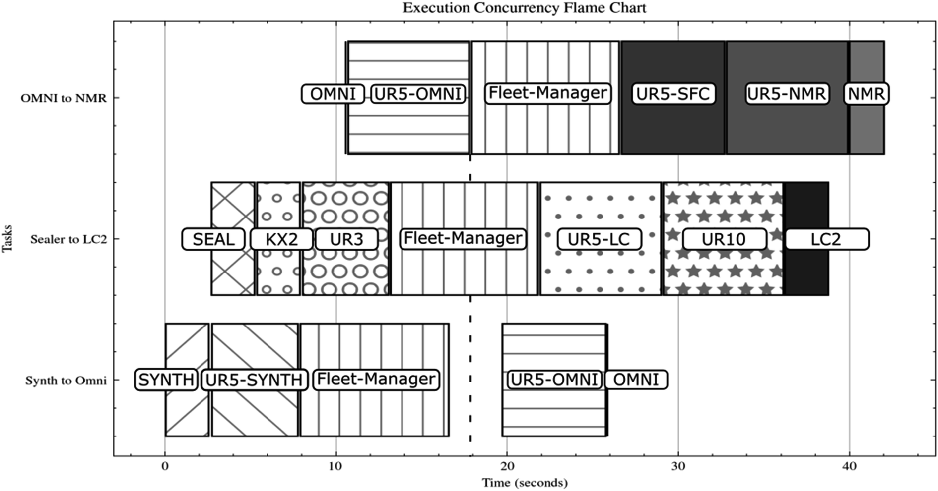 | ||
| Fig. 6 Illustrates the execution times of three parallel tasks called by the Swiss Cat+ Main Laboratory Scheduler (level 1) and coded into the level 2 Robot Sub-Scheduler based on a first-in, first-out (FIFO) strategy, as depicted in a flame chart. Each task (vertical scale), corresponding to a specific workflow, within the Robot Sub-Scheduler is conducted independently based on the availability of nodes. The execution times of the nodes are represented on the flame chart with different patterns for identification purposes and are named directly inside the chart. The nodes correspond primarily to the various types of hardware utilized by the workflows, including six-axis collaborative robots (UR…) and mobile robots (Fleet-Manager). It also mentions transfer times from or to the scientific equipment (NMR, SYNTH, LC2) and sample preparation equipment (SEAL & OMNI). The depicted times were obtained directly through the use of the execution time tracker accessible within the GLAS web interface. To ensure the accuracy of the measurements, a simulation was conducted in which all chemical operations were set to zero seconds, thereby isolating the communication and scheduling times. The vertical dotted line indicates the alignment with the operational delay of approximately two seconds, which is necessary to change the status and allow the UR5-OMNI node to restart the “Synth to Omni” task after the conclusion of the same node in the “OMNI to NMR” task. | ||
Fig. 6 exhibits an approximate activation time of 2 seconds upon restarting the UR5-OMNI node in the “Synth to OMNI” task following the conclusion of the same node in the “OMNI to NMR” task. This delay is attributed to the requisite time for the system to update the node status, thereby enabling its reuse for new assignments. The alignment between the two tasks is illustrated by the vertical dotted line. Furthermore, a shift of approximately 5 seconds at the inception of the three distinct tasks is also observable. This discrepancy can be attributed to the FIFO methodology employed by the Swiss Cat+ REST-API-based Main Laboratory Scheduler, which invokes the workflows at the level of the Robot Sub-Scheduler. It is evident from this figure that the GLAS parallelization substantially accelerates task execution in comparison to a pure FIFO approach, wherein all tasks are managed sequentially by a single main lab scheduler. In such a case, the total execution time would be the sum of the three workflows presented, with the addition of the same initial 5 second average shift between each node, resulting in a total of approximately 173 seconds instead of the 42 seconds shown in Fig. 6. It seems reasonable to posit that the ratio of 173/42 (approximately 4.2 times faster) between a centralized FIFO scheduling approach and the GLAS parallelized architecture would be maintained when chemical operation times are taken into account. Indeed, this ratio would likely be increased, given that these operations typically span a range of minutes to hours. The parallelization of these processes therefore has a significant impact. It could therefore be of great interest to extend the number of layers in order to increase the potential of parallelization. A detailed analysis of GLAS execution time in comparison with different scheduling methodologies as the Main Laboratory Scheduler is planned for future study.
3.2 OmniFire
 | ||
| Fig. 7 Description of the OmniFire system, including an illustration of its various components. In the CAO illustration on the left, item 1 depicts the UR5e 6-axis arm, item 2 represents the mobile robot (EM) utilized for long-range sample transfer (2D drone swarm, a subject of further elaboration in a forthcoming publication), item 3 portrays the Brooks Scara Robot PreciseFlex 3400, item 4 illustrates the intermediate plate employed for sample transfer between the Scara and the 6-axis, and item 5. The left valve system (Dispatcher) is mounted on a Cartesian axis and is dedicated to sample preparation and sealing for Agilent SFC-IM-Q-TOF (not visible) and Bruker HR-NMR (not visible). It also serves as a conduit for direct injection into the Agilent Cary 60 UV spectrophotometer (8) and into the Bruker Invenio FT-IR spectrophotometer (9). The right valve system is mounted on a dedicated Cartesian axis (7) and is used to collect the fractions into SBS plates directly from the Prep-LC (6). Finally, the track dedicated to the 2D drone swarm system (presented in a separate publication) is shown with number (10). The image on the right depicts the operational system as it is existing in the Swiss Cat+ laboratory. | ||
 | ||
| Scheme 2 High-level functional workflow of the OmniFire as it is operated in the Swiss Cat+ West Hub laboratory. | ||
As illustrated in Fig. 7, the OmniFire consists of two ensembles of valves associated with Cartesian positioning systems (5 and 7), two previously mentioned spectrophotometers Agilent Cary 60 UV-vis (8) and Bruker Invenio FT-IR (9). Additionally, the apparatus comprises an ensemble of sample management devices, including a six-axis Universal Robot 5e (1), a Brooks Scara robot PreciseFlex 3400 (3), an Agilent SBS plate sealer (not visible), and a 3D printer head utilized for sealing the NMR tubes (included in 5). All valves and Cartesian positioning systems are operated via a Beckhoff controller, which is not visible and forms the entirety of the “Dispatcher” system. Furthermore, the mobile robot (EM) utilized for sample transfer is visible on top, identified as number 2. The preparative LC (6) and the intermediate plate for sample transfer between the Scara and the 6-axis (4) are also present.
The entirety of the OmniFire, with the exception of the UR5e, which is overseen by the level 2 Robot Sub-Scheduler (use case 1 above, through horizontal dashed arrow in Fig. 5), is managed by a singular and dedicated sub-scheduler of level 2 as visible in Fig. 5 (red shot-dashed rounded square). This section provides a detailed description of the OmniFire level 2 sub-scheduler.
| Tool | Type of equipment | Role | Control system |
|---|---|---|---|
| Brooks PreciseFlex 3400 | Scara | Move plates internally | TCP communication |
| Cary 60 UV-vis spectrophotometer | Analysis tool for ultraviolet wavelengths | Analyze products from the plates | Agilent's ADL scripting language (will become SDK) |
| Invenio FT-IR spectrometer | Analysis tool for infrared wavelengths | Analyze products from the plates | Opus Python library |
| Dispatcher | In-house valve system | Sips and dispatches products from plates to analytical instrument and to external instruments | Beckhoff Twin CATs ADS library |
As GLAS is developed in Python, the utilization of wrappers is imperative to facilitate communication. For TCP communication over telnet and Twin CATs ADS, existing wrappers are available in the public domain and are open source.47,48 Regarding the Agilent ADL scripting language, ADL scripts had to be specifically written in order to be executed from GLAS. A new version in SDK will soon be implemented. In ESI S1,† two configuration examples specialized to the OmniFire are presented.
3.2.3.1 Traffic jam. A SBS plate sent from the OmniFire to an Agilent BRAVO liquid handler for dilution operations produces up to 10 new plates that will be reimported simultaneously into the OmniFire. This exceeds the capacity of the Dispatcher, which is unable to handle such a volume of plates at once. To avoid such issues, a storage bay is implemented, accessible by the Scara Brooks PreciseFlex 3400, to store plates while the Dispatcher is in use. In terms of GLAS, it is necessary for the node associated with the Scara to be able to behave in accordance with the status of the Dispatcher, i.e. orienting the plates correctly either towards the Dispatcher or towards the storage. In order to perform this, the Python script for this node must be written in multithreading. A code snippet for a GLAS workflow including multithreading is available in ESI S2.†
3.2.3.2 SBS plates collisions. As described above, GLAS is designed so that a node's status is set to 0 (available) when all of its Basic Methods (BMs) have been completed. When the implementation of GLAS consists of robotic arms that move plates around, the final physical position of the plate is directly correlated to the node status. This is not necessarily the case with the OmniFire or other nodes that have BMs not related to plate movement (e.g., chemical analyzers). The problem is that if the physical state of a plate is not properly defined, there is a risk of collision when two different tasks call the same node. To overcome this, the status of the plate's physical position must be systematically updated as the plates leave the node, not just when the BM is completed. This can be done by creating a new class that inherits the GLAS class “BaseNode” and overrides the execute() method so that the code is the same minus the state updates. Any subsequent node implementation can then inherit this new class. Their state updates can then be managed by the node that actually moves the plates, in this case the Scara Brooks Precise Flex 3400. A code snippet demonstrating how to create a custom node class is provided in ESI S3.†
4 Potential of use in various experimental laboratory types
The GLAS architecture, which is based on a multilayered Git system and is protocol agnostic, can be adapted to a wide range of laboratory types. As it is based on Basic Methods (BM) defined in proprietary software and can accommodate the majority of traditional communication protocols, it can be used to interface with the majority of existing laboratory equipment without the need for any specific API development. Subsequently, the sequences of operations (workflows) are defined in accordance with the requirements of the laboratory and can be presented as a list of steps. The overarching principle is to maintain the intelligence as close as possible at the Executor level. This approach facilitates the development and design of high-level schedulers with a relatively straightforward methodology. As previously outlined, GLAS is currently employed within the Swiss Cat+ framework to directly control laboratory instruments utilizing over six distinct protocols and application programming interfaces (APIs). Furthermore, the REST-API Level 1 Main Laboratory Scheduler oversees a level 2 Agilent Sample Scheduler environment and a level 2 Agilent VWorks environment. Furthermore, a level-2 Bruker Topspin-IconNMR environment is operational, as is another dedicated level-2 sub-scheduler for an ensemble of equipment comprising two Chemspeed Swing XL stations controlled by Autosuite and Arksuite, along with a group of five interconnected DEC/Jacomex glove boxes with robotic sample preparation functions. The aforementioned variety of interfaces and instruments provides compelling evidence in favor of a high degree of adaptability to a diverse range of laboratory settings. Another notable strength of the GLAS architecture is its adaptive web client (Fig. 4). Indeed, the web interface is fully customizable to any laboratory with minimal configuration. By modifying the configuration slightly to suit the laboratory environment, the user can readily display the status of ongoing tasks and the progress made in near real-time.5 Limitations
One of the few limitations of GLAS is the lack of sample tracking at the node level. Currently, this is managed at the global level by the Main Laboratory Scheduler, which is sufficient for the purposes of Swiss Cat+. A forthcoming version of GLAS will include sample tracking functionality at the node level. In the majority of laboratories, sample tracking is a mandatory requirement for compliance with regulatory standards. Such a feature would facilitate data integrity and consistency for samples handled by GLAS. Moreover, GLAS lacks the functionality to optimize workflows. At present, GLAS receives and launches tasks in a sequential manner (FIFO), but the task itself is executed on a different thread, allowing for the concurrent execution of multiple threads. The initiation of nodes within a task is contingent upon their designated workflow, occurring as soon as they become available. Consequently, operations on disparate nodes of disparate instruments may be conducted in parallel, unless a specific node is incorporated into multiple workflows. In this particular instance, the execution of a task based on one of these workflows may impede the operation of another task that utilizes the same node. It may, therefore, be of interest to consider optimizing the order in which workflows are called at the level of the Main Laboratory Scheduler, with a view to avoiding such interferences. To consider global scheduling optimization, the integration of algorithms such as those described by Itoh T. D. et al.49 and Arai Y. et al.50 at the level of the Main Laboratory Scheduler would undoubtedly facilitate this process. This would require the ability to escalate all equipment status updates via the nodes and experiment progress data in order to facilitate truly optimized dynamic scheduling. The retrieval of experimental progress information is not currently a standard feature of scientific equipment. However, the optimization of workflows, particularly in the context of chemistry, can become a highly complex undertaking due to the intrinsic uncertainty associated with the timing of chemical operations. Indeed, the precise timing of reactions and analyses is frequently uncertain, thereby rendering the prediction and optimization of BM or workflows a challenging endeavor. In addition, given the time required for operations at the various stations, several minutes per sample for spectroscopy and chromatography, i.e. hours for hundreds of samples, and also hours for synthesis steps, compared to transfer times of seconds to minutes, it becomes clear that most of the optimization effort must be done at the instrument level and then at the BM level. In the case of Swiss Cat+, the initial reduction in BM times has led to a significant reduction in overall workflow times.6 Summary and outlook
The Git-based GLAS environment is a novel and simple way to install a large-scale scheduling architecture in an automated laboratory with minimal configuration. The generated architecture can be easily extended and adapted to almost any type of scientific equipment and sample manipulation tools. This article defines the basic concepts used in GLAS, such as Basic Methods (BM), nodes, workflows, and tasks, and explains how to install and implement this solution. It also describes how the GLAS architecture naturally parallelize tasks. The description is illustrated with concrete use cases to give the reader enough confidence to implement this solution. In addition, the article presents the GLAS web client, which is able to display the tasks running in the lab and the status of the equipment.Data availability
The code for GLAS can be found at https://github.com/swisscatplus/glas/. The version of the code employed for this study is revision 11. A wiki is available at https://github.com/swisscatplus/glas/wiki as well as the code for the web-client https://github.com/swisscatplus/glas-web-client. Specific examples of multi-threaded workflows snippet codes corresponding to the presented workflows are given in ESI.†Author contributions
Conceptualization: J.-C. C., T. C., A. S., E. M., K. V., F. d. N., P. M. Funding acquisition: P. M. Investigation: J.-C. C., T. C., A. S., K. V., F. d. N. Methodology: J.-C. C., T. C., A. S., E. M., K. V. Project administration: J.-C. C., K. V., P. M. Resources: E. M., K. V. Software: J.-C. C., T. C., A. S. Supervision: J.-C. C., E. M., P. M. Validation: J.-C. C., E. M., P. M. Visualization: J.-C. C., E. M., P. M. Writing (original draft): J.-C. C., T. C., A. S., P. M. Writing (review and editing): J.-C. C., T. C., A. S., P. M.Conflicts of interest
There are no conflicts of interest to declare.Acknowledgements
The authors acknowledge the ETH Domain for its support through the Forschungsinfrastrukturen Program. The authors would like to extend their gratitude to the EPFL, SB, and ISIC administrations for their assistance. Furthermore, they would like to acknowledge the invaluable collaboration and guidance provided by Prof. F. Glück and Dr G. Chanel from HEPIA in Geneva in the supervision of Tanguy Cavagna and Alec Schmidt in the context of their Bachelor's thesis program. The text was enhanced through the use of Deepl Write Pro.References
- R. J. Spinrad, Automation in the Laboratory. On-Line Computers Are Providing New Freedom in the Design and Conduct of Experiments, Science, 1967, 158(3797), 55–60, DOI:10.1126/science.158.3797.55.
- J. Boyd, Robotic Laboratory Automation, Science, 2002, 295(5554), 517–518, DOI:10.1126/science.295.5554.517.
- R. D. King, J. Rowland, S. G. Oliver, M. Young, W. Aubrey, E. Byrne, M. Liakata, M. Markham, P. Pir, L. N. Soldatova, A. Sparkes, K. E. Whelan and A. Clare, The Automation of Science, Science, 2009, 324(5923), 85–89, DOI:10.1126/science.1165620.
- M. Christensen, L. P. E. Yunker, F. Adedeji, F. Häse, L. M. Roch, T. Gensch, G. dos Passos Gomes, T. Zepel, M. S. Sigman, A. Aspuru-Guzik and J. E. Hein, Data-Science Driven Autonomous Process Optimization, Commun. Chem., 2021, 4(1), 112, DOI:10.1038/s42004-021-00550-x.
- R. L. Greenaway, K. E. Jelfs, A. C. Spivey and S. N. Yaliraki, From Alchemist to AI Chemist, Nat. Rev. Chem, 2023, 7(8), 527–528, DOI:10.1038/s41570-023-00522-w.
- K. Thurow and S. Junginger, Devices and Systems for Laboratory Automation, Wiley, 1st edn, 2022, DOI:10.1002/9783527829446.
- F. de Nanteuil and P. Miéville, Modern Automation in Organic Synthesis Laboratories, in Comprehensive Organic Synthesis, Elsevier, 2024 Search PubMed.
- G. Tom, S. P. Schmid, S. G. Baird, Y. Cao, K. Darvish, H. Hao, S. Lo, S. Pablo-García, E. M. Rajaonson, M. Skreta, N. Yoshikawa, S. Corapi, G. D. Akkoc, F. Strieth-Kalthoff, M. Seifrid and A. Aspuru-Guzik, Self-Driving Laboratories for Chemistry and Materials Science, Chem. Rev., 2024, 124(16), 9633–9732, DOI:10.1021/acs.chemrev.4c00055.
- A. Nandy, C. Duan and H. J. Kulik, Audacity of Huge: Overcoming Challenges of Data Scarcity and Data Quality for Machine Learning in Computational Materials Discovery, Curr. Opin. Chem. Eng., 2022, 36, 100778, DOI:10.1016/j.coche.2021.100778.
- A. Thakkar, T. Kogej, J.-L. Reymond, O. Engkvist and E. Jannik Bjerrum, Datasets and Their Influence on the Development of Computer Assisted Synthesis Planning Tools in the Pharmaceutical Domain, Chem. Sci., 2020, 11(1), 154–168, 10.1039/C9SC04944D.
- C. W. Coley, N. S. Eyke and K. F. Jensen, Autonomous Discovery in the Chemical Sciences Part I: Progress, Angew. Chem., Int. Ed., 2020, 59(51), 22858–22893, DOI:10.1002/anie.201909987.
- C. W. Coley, N. S. Eyke and K. F. Jensen, Autonomous Discovery in the Chemical Sciences Part II: Outlook, Angew. Chem., Int. Ed., 2020, 59(52), 23414–23436, DOI:10.1002/anie.201909989.
- M. P. Maloney, C. W. Coley, S. Genheden, N. Carson, P. Helquist, P.-O. Norrby and O. Wiest, Negative Data in Data Sets for Machine Learning Training, Org. Lett., 2023, 25(17), 2945–2947, DOI:10.1021/acs.orglett.3c01282.
- T. Taniike and K. Takahashi, The Value of Negative Results in Data-Driven Catalysis Research, Nat. Catal., 2023, 6(2), 108–111, DOI:10.1038/s41929-023-00920-9.
- D. Caramelli, D. Salley, A. Henson, G. A. Camarasa, S. Sharabi, G. Keenan and L. Cronin, Networking Chemical Robots for Reaction Multitasking, Nat. Commun., 2018, 9(1), 3406, DOI:10.1038/s41467-018-05828-8.
- D. T. Ahneman, J. G. Estrada, S. Lin, S. D. Dreher and A. G. Doyle, Predicting Reaction Performance in C–N Cross-Coupling Using Machine Learning, Science, 2018, 360(6385), 186–190, DOI:10.1126/science.aar5169.
- S. Kariofillis, S. Jiang, A. Żurański, S. Gandhi, J. Martinez Alvarado and A. Doyle, Using Data Science to Guide Aryl Bromide Substrate Scope Analysis in a Ni/Photoredox-Catalyzed Cross-Coupling with Acetals as Alcohol-Derived Radical Sources, ChemRxiv, 2021, preprint, DOI:10.33774/chemrxiv-2021-6kd0t.
- P. Schwaller, A. C. Vaucher, R. Laplaza, C. Bunne, A. Krause, C. Corminboeuf and T. Laino, Machine Intelligence for Chemical Reaction Space, WIREs Computational Molecular Science, 2022, 12(5), e1604, DOI:10.1002/wcms.1604.
- J. H. Montoya, K. T. Winther, R. A. Flores, T. Bligaard, J. S. Hummelshøj and M. Aykol, Autonomous Intelligent Agents for Accelerated Materials Discovery, Chem. Sci., 2020, 11(32), 8517–8532, 10.1039/D0SC01101K.
- J. H. Montoya, M. Aykol, A. Anapolsky, C. Gopal, P. K. Herring, J. Hummelshøj, L. Hung, H.-K. Kwon, D. Schweigert, S. Sun, S. Suram, S. B. Torrisi, A. Trewartha and B. Storey, Toward Autonomous Materials Research: Recent Progress and Future Challenges, Appl. Phys. Rev., 2022, 9, 011405, DOI:10.1063/5.0076324.
- K. Thurow, System Concepts for Robots in Life Science Applications, Appl. Sci., 2022, 12(7), 3257, DOI:10.3390/app12073257.
- T. Kranjc, Introduction to Laboratory Software Solutions and Differences Between Them, in Digital Transformation of the Laboratory, John Wiley & Sons, Ltd, 2021, pp. 75–84, DOI:10.1002/9783527825042.ch3.
- L. Cao, D. Russo and A. A. Lapkin, Automated Robotic Platforms in Design and Development of Formulations, AIChE J., 2021, 67(5), e17248, DOI:10.1002/aic.17248.
- M. M. Flores-Leonar, L. M. Mejía-Mendoza, A. Aguilar-Granda, B. Sanchez-Lengeling, H. Tribukait, C. Amador-Bedolla and A. Aspuru-Guzik, Materials Acceleration Platforms: On the Way to Autonomous Experimentation, Curr. Opin. Green Sustainable Chem., 2020, 25, 100370, DOI:10.1016/j.cogsc.2020.100370.
- J. Bai, L. Cao, S. Mosbach, J. Akroyd, A. Lapkin and M. Kraft, From Platform to Knowledge Graph: Evolution of Laboratory Automation, JACS Au, 2022, 2, 292–309, DOI:10.1021/jacsau.1c00438.
- Z. Huang, M. S. Chen, C. P. Woroch, T. E. Markland and M. W. Kanan, A Framework for Automated Structure Elucidation from Routine NMR Spectra, Chem. Sci., 2021, 12(46), 15329–15338, 10.1039/D1SC04105C.
- T. Kind and O. Fiehn, Advances in Structure Elucidation of Small Molecules Using Mass Spectrometry, Bioanalytical Reviews, 2010, 2(1–4), 23–60, DOI:10.1007/s12566-010-0015-9.
- M. Pesek, A. Juvan, J. Jakoš, J. Košmrlj, M. Marolt and M. Gazvoda, Database Independent Automated Structure Elucidation of Organic Molecules Based on IR, 1H NMR, 13C NMR, and MS Data, J. Chem. Inf. Model., 2021, 61(2), 756–763, DOI:10.1021/acs.jcim.0c01332.
- M. O. Marcarino, S. Cicetti, M. M. Zanardi and A. M. Sarotti, A Critical Review on the Use of DP4+ in the Structural Elucidation of Natural Products: The Good, the Bad and the Ugly. A Practical Guide, Nat. Prod. Rep., 2022, 39(1), 58–76, 10.1039/D1NP00030F.
- J. S. Lindsey, A Retrospective on the Automation of Laboratory Synthetic Chemistry, Chemom. Intell. Lab. Syst., 1992, 17(1), 15–45, DOI:10.1016/0169-7439(92)90025-B.
- T. M. Alam and M. K. Alam, Chemometric Analysis of NMR Spectroscopy Data: A Review, Annu. Rep. NMR Spectrosc., 2004, 54, 41–80, DOI:10.1016/S0066-4103(04)54002-4.
- R. G. Brereton, J. Jansen, J. Lopes, F. Marini, A. Pomerantsev, O. Rodionova, J. M. Roger, B. Walczak and R. Tauler, Chemometrics in Analytical Chemistry—Part I: History, Experimental Design and Data Analysis Tools, Anal. Bioanal. Chem., 2017, 409(25), 5891–5899, DOI:10.1007/s00216-017-0517-1.
- T. S. Bos, J. Boelrijk, S. R. A. Molenaar, B. van ’t Veer, L. E. Niezen, D. van Herwerden, S. Samanipour, D. R. Stoll, P. Forré, B. Ensing, G. W. Somsen and B. W. J. Pirok, Chemometric Strategies for Fully Automated Interpretive Method Development in Liquid Chromatography, Anal. Chem., 2022, 94(46), 16060–16068, DOI:10.1021/acs.analchem.2c03160.
- Á. Wolf, D. Wolton, J. Trapl, J. Janda, S. Romeder-Finger, T. Gatternig, J.-B. Farcet, P. Galambos and K. Széll, Towards Robotic Laboratory Automation Plug & Play: The “LAPP” Framework, SLAS Technol., 2022, 27(1), 18–25, DOI:10.1016/j.slast.2021.11.003.
- K. F. Jensen, Flow Chemistry—Microreaction Technology Comes of Age, AIChE J., 2017, 63(3), 858–869, DOI:10.1002/aic.15642.
- A. Slattery, Z. Wen, P. Tenblad, J. Sanjosé-Orduna, D. Pintossi, T. den Hartog and T. Noël, Automated Self-Optimization, Intensification, and Scale-up of Photocatalysis in Flow, Science, 2024, 383(6681), eadj1817, DOI:10.1126/science.adj1817.
- S. P. Gilroy and B. A. Kaplan, Furthering Open Science in Behavior Analysis: An Introduction and Tutorial for Using GitHub in Research, Perspectives on Behavior Science, 2019, 42(3), 565–581, DOI:10.1007/s40614-019-00202-5.
- D. Moreau, K. Wiebels and C. Boettiger, Containers for Computational Reproducibility, Nat. Rev. Methods Primers, 2023, 3(1), 1–16, DOI:10.1038/s43586-023-00236-9.
- M. Seifrid, F. Strieth-Kalthoff, M. Haddadnia, T. Wu, E. Alca, L. Bodo, S. Arellano-Rubach, N. Yoshikawa, M. Skreta, R. Keunen and A. Aspuru-Guzik, Chemspyd: An Open-Source Python Interface for Chemspeed Robotic Chemistry and Materials Platforms, ChemRxiv, 2024, preprint, DOI:10.26434/chemrxiv-2024-33sfl.
- W. Cedeño and P. A. Laplante, An Overview of Real-Time Operating Systems, JALA, 2007, 12(1), 40–45, DOI:10.1016/j.jala.2006.10.016.
- GLAS Github wiki, GitHub, https://github.com/swisscatplus/glas/wiki/Home, accessed 2024-06-18 Search PubMed.
- M. D. Hanwell, W. A. de Jong and C. J. Harris, Open Chemistry: RESTful Web APIs, JSON, NWChem and the Modern Web Application, J. Cheminf., 2017, 9(1), 55, DOI:10.1186/s13321-017-0241-z.
- Swisscatplus/Glas-Web-Client, 2024, https://github.com/swisscatplus/glas-web-client, accessed 2024-06-19.
- P. Laveille, P. Miéville, S. Chatterjee, E. Clerc, J.-C. Cousty, F. de Nanteuil, E. Lam, E. Mariano, A. Ramirez, U. Randrianarisoa, K. Villat, C. Copéret and N. Cramer, Swiss CAT+, a Data-Driven Infrastructure for Accelerated Catalysts Discovery and Optimization, Chimia, 2023, 77(3), 154–158, DOI:10.2533/chimia.2023.154.
- Universal Robots RTDE C++ Interface — ur_rtde 1.5.8 documentation, https://sdurobotics.gitlab.io/ur_rtde/, accessed 2024-07-08 Search PubMed.
- Real-Time Data Exchange (RTDE) Guide – 22229, https://www.universal-robots.com/articles/ur/interface-communication/real-time-data-exchange-rtde-guide/, accessed 2024-07-08 Search PubMed.
- S. Lehmann, Stlehmann/Pyads, 2024, https://github.com/stlehmann/pyads, accessed 2024-07-08 Search PubMed.
- cpython/Lib/telnetlib.py at 3.12 · python/cpython, GitHub, https://github.com/python/cpython/blob/3.12/Lib/telnetlib.py, accessed 2024-07-08 Search PubMed.
- T. D. Itoh, T. Horinouchi, H. Uchida, K. Takahashi and H. Ozaki, Optimal Scheduling for Laboratory Automation of Life Science Experiments with Time Constraints, SLAS Technol., 2021, 26(6), 650–659, DOI:10.1177/24726303211021790.
- Y. Arai, K. Takahashi, T. Horinouchi, K. Takahashi and H. Ozaki, SAGAS: Simulated Annealing and Greedy Algorithm Scheduler for Laboratory Automation, SLAS Technol., 2023, 28(4), 264–277, DOI:10.1016/j.slast.2023.03.001.
Footnotes |
| † Electronic supplementary information (ESI) available. See DOI: https://doi.org/10.1039/d4dd00253a |
| ‡ Authors contributed equally. |
| This journal is © The Royal Society of Chemistry 2024 |