
 Open Access Article
 This Open Access Article is licensed under a
 Creative Commons Attribution 3.0 Unported Licence
Molecular graph transformer: stepping beyond ALIGNN into long-range interactions†
Marco
Anselmi
a,
Greg
Slabaugh
*b,
Rachel
Crespo-Otero
 *c and
Devis
Di Tommaso
*a
*c and
Devis
Di Tommaso
*a
aSchool of Physical and Chemical Sciences, Queen Mary University of London, Mile End Rd, Bethnal Green, London, E1 4NS, UK. E-mail: d.ditommaso@qmul.ac.uk
bDigital Environment Research Institute, Queen Mary University of London, Empire House, 67-75 New Road, London, E1 1HH, UK. E-mail: g.slabaugh@qmul.ac.uk
cDepartment of Chemistry, University of College London, 20 Gordon Street, London WC1H 0AJ, UK. E-mail: r.crespo-otero@ucl.ac.uk
First published on 23rd April 2024
Abstract
Graph Neural Networks (GNNs) have revolutionized material property prediction by learning directly from the structural information of molecules and materials. However, conventional GNN models rely solely on local atomic interactions, such as bond lengths and angles, neglecting crucial long-range electrostatic forces that affect certain properties. To address this, we introduce the Molecular Graph Transformer (MGT), a novel GNN architecture that combines local attention mechanisms with message passing on both bond graphs and their line graphs, explicitly capturing long-range interactions. Benchmarking on MatBench and Quantum MOF (QMOF) datasets demonstrates that MGT's improved understanding of electrostatic interactions significantly enhances the prediction accuracy of properties like exfoliation energy and refractive index, while maintaining state-of-the-art performance on all other properties. This breakthrough paves the way for the development of highly accurate and efficient materials design tools across diverse applications.
1 Introduction
Across various scientific disciplines, from computer vision to chemistry, graphs serve as powerful models for representing systems of objects and interactions. A graph G = (V, E) consists of a set of nodes V and a set of edges E between pairs of nodes, representing the relationship between them. Geometric Deep Learning (GDL) leverages the expressive power of graphs to analyze these systems, providing insights into their underlying structure. Common applications of GDL include shape analysis and pose recognition in computer vision,1 link and community detection on social media networks,2–4 representation learning on textual graphs,5,6 medical image analysis for disease detection7–9 and property prediction for molecular and crystalline materials.10–18In the field of quantum chemistry, the development of Graph Neural Networks (GNN) has provided a means of computing the properties of molecules and solids, without the need to approximate the solution to the Schrödinger equation. Furthermore, compared to other Machine Learning (ML) techniques, they have shown immense potential in the field of chemistry, since they do not require manual feature engineering and have significantly better performance compared to other ML models.19 GNN models represent molecules or crystalline materials as graphs with a node for each constituent atom and an edges as bonds or inter-atomic relationships. By passing messages through the edges they update the molecular representation and learn the function that maps these graphs to properties obtained from reference electronic structure calculations such as Density Functional Theory (DFT).
There has been rapid progress in the development of GNN architectures for predicting material properties, such as such as SchNet,10 Crystal Graph Convolutional Neural Network (CGCNN),11 MatErials Graph Network (MEGNet),12 Atomistic Line Graph Neural Network (ALIGNN)13 and similar variants.14–18,20–25 These models consider only the pairwise interactions between bonded atoms or between atoms within a cut-off radius of typically 6 Å to 8 Å. Some have also incorporated many-body relationships, such as bond-angles, into the molecular representation.13,14,16,17,20 Nevertheless, all of these GNN models developed so far can be categorised as local methods26 and are limited to analysing only the local environment around atoms or relying on multiple message passing layers to approximate long range interactions.
However, for certain systems and/or tasks, long range interactions can be important. To date there are only a few ML models that have incorporated electrostatic interactions into their architecture.27–30 One of the most important contributions to the long-range interactions is electrostatics, which, together with van der Waals, define non-bonded interactions in the potential energy (PE) equation (eqn (1)).
 | (1) |
Although non-bonded interactions are composed of both electrostatic and van der Waals interactions, as the latter decays much faster, it is less relevant for the purpose of modelling long-range interactions. Thus, to represent long-range interactions only the electrostatic are necessary. The electrostatic interaction between two atoms in a structure can be obtained using Coulomb's law, shown in eqn (2).
 | (2) |
The other component to the non-bonding energy, the van der Waals interactions, unlike electrostatics, does not have a simplified representation. Thus, to obtain the van der Walls energy, it would require the calculation of the parameters of the Lennard-Jones potential, making it unsuitable as a potential descriptor of the pair-wise interaction between atoms in a ML architecture.
With the aim of enhancing GNN architectures akin to ALIGNN13 for the incorporation of long-range interactions, this paper introduces the Molecular Graph Representation (MGR) and the Molecular Graph Transformer (MGT). In this endeavour, the simplified Coulomb interactions that can be obtained from the Coulomb Matrix31 are explicitly included within the MGR and subsequently analysed by the MGT. The MGR splits the graphical representation of the system into three graphs: local graph (Glocal), line graph (Gline), and fully connected graph (Gglobal). The MGT alternates between graph attention layers on the Gglobal and graph convolutions on the Gline and Glocal, to update the molecular representation through non-bonding, three-body and two-body information. Our model is trained on both the MatBench32 and the QMOF33 to predict energetic, electronic and vibrational properties of solid-state materials directly from their unrelaxed structures.
2 Related work
2.1 Message passing neural networks
Graph Neural Networks (GNNs) are a type of neural networks that learn a mapping between graph-structured data and a target space. Message Passing Neural Networks34 (MPNNs) are a specific variation of GNNs, where a layer updates node features by enabling information exchange and aggregation between neighbouring nodes in a graph. Consider a Graph G = (V, E), with nodes vi ∈ V and edges eij ∈ E, and representations hti and etij for nodes and edges, respectively, at layer t. The message passing steps can then be described as: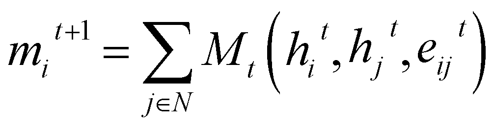 | (3) |
| hit+1 = Ut(hit,mit+1) | (4) |
Restricting the input to unordered graph-structure data allows all GNNs to be invariant to permutations in the input. Furthermore, by acting only node and edge features – hi, eij – composed of scalar values, such as atomic numbers for nodes and interatomic distances for edges, makes MPNNs invariant to geometric symmetry group E(3) operations – rotation, inversion and translation. This is a desirable property since prediction tasks for most scalar properties, such as molecular energy prediction, require E(3) invariance. Whereas, the inclusion of vector graph features and the prediction of vector properties, such as atomic forces, require E(3) equivariance. Recently, a class of models known as equivariant neural networks35–40 have been developed which can act directly on vector inputs, while maintaining equivariance, by using equivariant operations only.
2.2 Attention mechanisms
The concept of attention in neural networks was first introduced in the transformer architecture proposed by Vaswani et al. (2017).41 The traditional transformer was applied to text represented as sequences of tokens. In the field of computational chemistry, previous works applied attention mechanism to text representations of structures,42–44 usually simplified molecular-input line-entry system (SMILES),45 treating the prediction as a machine translation task.In the context of GNNs, however, the input data structure is a graph. To adapt attention mechanisms to graph, on can interpret the original self-attention as constructing a fully connected graph over the input tokens and computing interactions between them. Recently many attempts have been made to adapt attention mechanisms to MPNNs. Most notably the Graph Attention (GAT) Network introduced by Veličković, et al.46 and the GATv2 introduced by Brody et al.47 which implement an attention function closely following the work of Bahdanau et al.48 while using the multi-headed approach of the transformer. Other works5,49–51 have tried to adapt the transformer directly to MPNNs with one of the most common research fields being on positional encodings.
3 Molecular graph transformer
3.1 Molecular graph representation
The Glocal, Gline, and Gglobal sub-graphs of the MGR are used to represent both the bonded and non-bonded interactions between atoms. The local and line graph both describe bonded interactions, with the local graph describing pair-wise interactions (red edges in Fig. 1), and the line graph describing 3-body interactions using angles between triplets of atoms (green edge in Fig. 1). These two graphs can be considered the equivalent of Estretching and Eangle in the PE equation. The full graph is based on the Coulomb Matrix31 representation, and it is used to represent the non-bonded interactions between pairs of atoms (blue edges in Fig. 1), making it the equivalent of the Eelectrostatic term in eqn (1). | ||
| Fig. 1 Schematic showing the Molecular Graph Representation (MGR). For simplicity, only an atom connected to three other atoms is shown. Molecules are encoded by converting each atom i into a vector representation hi. Using the local graph interactions between atoms i, j are dependent on their representations hi, hj and the distance between them eij. While, using the line graph interactions between triplets of atoms i, j, k are dependent on the distance between pairs of atoms eij, ejk and the angle between the atoms tij,jk(tijk). Lastly, using the full graph the interaction between pairs of atoms I, J are dependent on their vector representation hi, hj and the Coulomb repulsion between them fij. | ||
The construction of the local and line graphs is the same as the ALIGNN13 representation. The local graph is constructed using a periodic 12-nearest-neighbour methodology, in which an edge is formed between an atom and its 12 nearest neighbours within a cut-off distance of 8 Å. Each atom is then assigned a nine features feature set based on its atomic species: (1) electronegativity; (2) covalent radius; (3) valence electrons; (4) group number; (5) electron affinity; (6) first ionization energy; (7) period number; (8) block number; (9) atomic volume. The feature sets are then encoded, through one-hot encoding, to form the feature vectors of the atoms. The edges are instead initialized with the distance between the two atoms that they connect. To form the feature vectors for the edges, a Radial Basis Function (RBF) is used with limits: 0 Å and 8 Å. The local graph can then be defined as Glocal = (h, e), where h are nodes and e are edges between pair of atoms, and Glocal has associated feature sets H = {h1, …, hi, …, hN} and E = {eij, eik, ekl, emi, …}, where hi is the feature vector given to node i and eij is the feature vector of the edge connecting nodes i and j.
The line graph is derived from the local graph. Each node in the line graph represents an edge in the local graph, and nodes and corresponding edges share the same feature vector, such that any update on a node of the line graph is reflected on the corresponding edge in the local graph. Edges in the line graph, correspond to the relationship between pairs of edges in the local graph that have one atom in common, representing a three-body interaction system between triplets of atoms, i.e. bond pair eij, eik and atom triplet hi, hj, hk where atom hi is the shared atom. The line graph edge features are given by an RBF expansion of the angle formed by two connected local graph edges, shown in green in Fig. 1. The line graph can then be defined as Gline = (e, t), where e are local graph edges and t are angles between connected edges or atom triplets, and Gline has associated feature sets E = {eij, eik, ekl, emi, …} and T = {tijk, tikl, tijm, …}.
The full graph is constructed similarly to the local graph. Each node in the local graph represents an atom in the structure, and it shares its latent representation with the nodes of the local graph. Edges in the full graph represent an interaction between pairs of atoms, and they are formed between all atoms that are within a cut-off distance from each other. Full graph edges features are derived from the Coulomb matrix31 of the structure and they represent the Coulomb repulsion between the two different atoms as described in the Coulomb matrix in eqn (5)
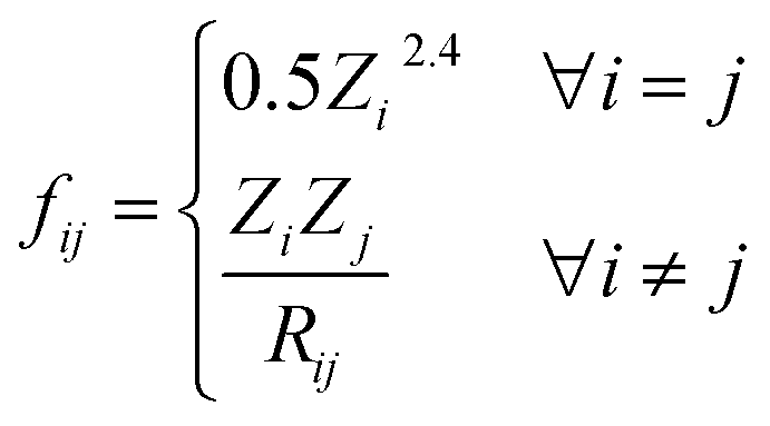 | (5) |
3.2 Molecular encoder
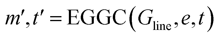
The main part of the MGT is the encoder module. This module executes updates on the nodes and edges of the MGR, by applying different update functions based on the sets of edges provided by the three parts of the MGR. Using the edges provided by the Gglobal, the module updates the nodes using Multi-Headed Attention (MHA). The encoder, then, uses a series of Edge Gated Graph Convolution (EGCC) modules, which are aggregated into a block called the ALIGNN block, to update the edges and nodes of both the Gline and the Glocal. Outside of the ALIGNN block, the EGCC module is also used for a further update to the edges and nodes of the Glocal. Lastly, the encoder also performs a final update on the nodes without using any edge information by running the nodes through a linear block, which, contains a fully connected layer with a SiLU activation function, followed by another fully connected layer.The modifications to the feature vectors follow a global-to-local sequence. Initially, nodes for increased attention are determined through non-bonding two-body interactions from the global graph, followed by updates using the same interactions. Subsequently, utilizing the line graph, updates involving three-body interactions are executed, succeeded by updates involving two-body interactions from the local graph. Lastly, updates based on single-body information are performed using only the node information.
| Q = WQhi, K = WKhj, V = WVhj, F = WFfij | (6) |
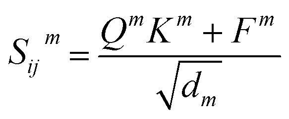 | (7) |
 | (8) |
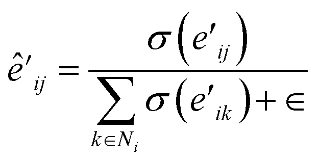
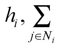 denotes the summation with all the neighbours of node hi, and softmax is used to normalize each message along the edges of node hi such that:
 | (9) |
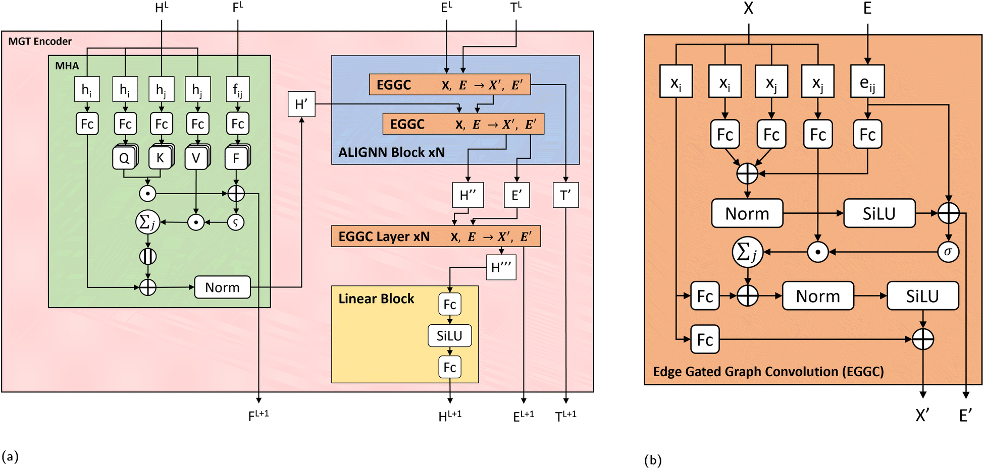 | ||
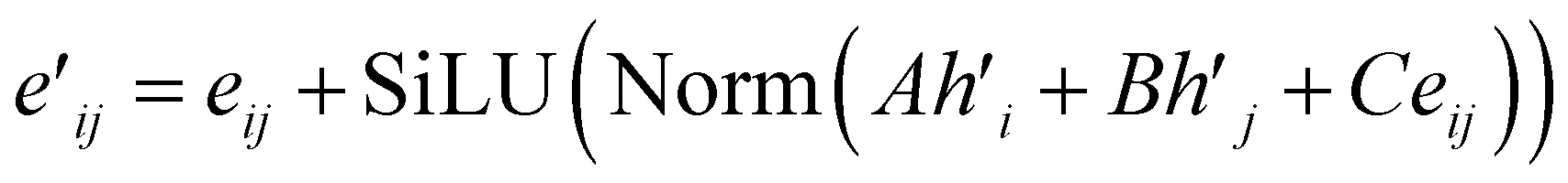
| Fig. 2 (a) Molecular Graph Transformer (MGT) Encoder layer architecture. For the current layer L of the model, the node (HL) embeddings are first updated using Multi-Headed Attention (MHA). The node features of central atoms hi and neighbouring atoms hj are separated and updated through individual linear layers. Attention scores are computed using atoms i, j and coulomb repulsions (FL) between them, and used to select features of atoms j. Selected features of atoms j are added to core atoms i to update their features and further refined through residual and normalization steps. The updated node features H′ from the MHA block are then used as input to the ALIGNN block, which uses a series of Edge Gated Graph Convolutions (EGGC) to update the input node features H′ using edge information from the line graph TL and local graph EL. The ALIGNN block, returns updated node features H′′, updated edge features E′ and updated triplet features T′. Node features H′′ are then further refined through N EGGC layers using edge features E′. Lastly the output features from the EGGC layers, H′′′, are then refined through a linear block, which passes them through two linear layers with a SiLU activation function between then. (b) Edge Gated Graph Convolution (EGGC) module. Each EGGC module splits its input node features (X) into core nodes xi and neighbouring nodes xj and are refined through separate linear layers. Using edge features eij, core nodes i and neighbouring nodes j, edge messages are computed and then added to core atoms i to update their representation. The EGGC then returns the edge message as an updated edge information (E′) and the updated node informations (X′). | ||
The update to each node is then defined as:
 | (10) |
 | (11) |
 | (12) |
 | (13) |
 | (14) |
 and eij respectively.
 | (15) |
 | (16) |
3.3 Overall model architecture
The MGT, shown in Fig. 3, is composed of M encoder layers, with a pooling function, applied on the edge features of all three graphs, in between the encoders. After M encoder layers we then apply a global pooling function to aggregate the node features into one feature for the whole graph. Finally to predict the properties of the input structure or perform classification on it, we apply a fully connected regression or classification layer. Table 1 shows the hyper-parameters that were used to train the model with which we obtained the results shown in the Results and discussion section. These hyper-parameters were obtained through hypothesis-driven hyper-parameter search. | ||
| Fig. 3 Flowchart for the overall model architecture. The nodes and edges from the MGR are first transformed to feature vectors through encoding layers for the nodes and each edge type. The feature vectors are then passed through a series of MGT Encoder layers each with the same dimension. The output node features from the MGT encoders are then aggregated using a pooling function to create a global feature vector for the whole structure. The global features are then refined through a linear layer, which, provides the output to the model. For this paper, 2 MGT encoder were used, with an input and output feature length of 512. | ||
| Parameter | Value |
|---|---|
| Encoder layers | 2 |
| MHA layers | 1 |
| ALIGNN blocks | 3 |
| EGGC layers | 1 |
| Atom input features | 90 |
| Edge input features | 80 |
| Angle input features | 40 |
| Coulomb input features | 120 |
| Embedding features | 256 |
| Hidden features | 512 |
| FC layer features | 128 |
| Global pooling function | Average |
| Batch size per GPU | 2 |
| Learning rate | 0.0001 |
3.4 Model implementation and training
The MGT is implemented using PyTorch53 and the Deep Graph Library.54 The code also relies on Pytorch Fabric for the distribution of the model across multiple GPUs and devices. For regression tasks the loss is obtained using the Mean Squared Error (MSE) function, while the error is obtained using the Mean Average Error (MAE) function. The models trained on the MatBench database were trained for 300 epochs. However, for the QMOF database, given that the structures are, on average, larger, resulting in larger graph representation, the models were trained for 100 epochs due to computational resources limitations. For all models the Adam optimizer was used with a weight decay of 10−5 and a learning rate of 0.0001. Calculations were performed using the Sulis Tier 2 HPC platform and on the JADE 2 Tier 2 HPC platform. On the Sulis HPC at most 5 nodes with 3 A100 40GB GPUs were used, while on JADE 2 the model was trained on 8 V100 32GB GPUs.4 Results and discussion
4.1 Performance on datasets
The MGT was created with the purpose of predicting properties of solid-state materials from their unrelaxed structures. To evaluate its performance, the Materials Project's MatBench32 version 0.1 dataset and the QMOF33 version 14 database were used. The MatBench32 dataset encompasses eight distinct regression tasks, each associated with an individual database containing a varied number of structures, ranging from 636 for the “jdft2d” task to 106![[thin space (1/6-em)]](https://www.rsc.org/images/entities/char_2009.gif) 113 for the “Formation Energy” task. As reported by Dunn et al.,32 each task has been appropriately curated, according to specific per-task procedures, to ensure that there is no extraneous data and biases in the datasets.
113 for the “Formation Energy” task. As reported by Dunn et al.,32 each task has been appropriately curated, according to specific per-task procedures, to ensure that there is no extraneous data and biases in the datasets.
The “jdft2d” task involves predicting the exfoliation energy for separating 2D layers from crystal structures, computed with the OptB88vdW55 and TBmBJ56 exchange–correlation DFT functionals. The “Phonons” task is dedicated to predicting the vibrational properties of crystal structures computed using the ABINIT code within the harmonic approximation based on density functional perturbation theory. The “Dielectric” task is concerned with predicting refractive index from crystal structures. The “log10 GVRH” and “log10 KVRH” tasks involve predicting the logarithm (base 10) of the shear (GVRH) and bulk (KVRH) modulus property of crystal structures. The “Bandgap” task focuses on the prediction of the electronic bandgap of crystal structures computed with the Perdew–Burke–Ernzerhor57 (PBE) functional. Lastly the “Perovskites” and “Formation energy” tasks are dedicated to predicting the formation energy of crystal structures, with the “Perovskites” task focusing on perovskites. For all the tasks, the train-test splits provided by the MatBench api, which avoid data leakage between the splits, were used. The training set was then divided into train-validation splits, consisting of approximately 80% and 20%, respectively, for each task. The performance of the MGT model on the MatBench dataset is shown in Table 2.
| Tasks | jdft2d | Phonons | Dielectric | log10 GVRH |
log10 KVRH |
Perovskites | Bandgap | Formation E |
|---|---|---|---|---|---|---|---|---|
| Units | meV per atom | cm−1 | Unitless | log10GPa |
log10GPa |
eV per unit cell | eV | eV per atom |
| ALIGNN | 43.4244 (8) | 29.5385 (3) | 0.3449 (13) | 0.0715 (3) | 0.0568 (5) | 0.0288 (2) | 0.1861 (3) | 0.0215 (3) |
| AMMExpress v2020 | 39.8497 (6) | 56.1706 (13) | 0.3150 (6) | 0.0874 (10) | 0.0647 (9) | 0.2005 (12) | 0.2824 (13) | 0.1726 (15) |
| CGCNN v2019 | 49.2440 (13) | 57.7635 (14) | 0.5988 (15) | 0.0895 (11) | 0.0712 (12) | 0.0452 (9) | 0.2972 (14) | 0.0337 (7) |
| coNGN | 36.1698 (5) | 28.8874 (2) | 0.3142 (5) | 0.0670 (1) | 0.0491 (1) | 0.0290 (3) | 0.1697 (2) | 0.0178 (2) |
| coGN | 37.1652 (4) | 29.7117 (4) | 0.3088 (4) | 0.0689 (2) | 0.0535 (2) | 0.0269 (1) | 0.1559 (1) | 0.0170 (1) |
| CrabNet | 45.6104 (9) | 55.1114 (12) | 0.3234 (9) | 0.1014 (14) | 0.0758 (13) | 0.4065 (14) | 0.2655 (12) | 0.0862 (13) |
| DimeNet++ (kgcnn v2.1.0) | 49.0243 (12) | 37.4619 (6) | 0.3400 (12) | 0.0792 (6) | 0.0572 (6) | 0.0376 (8) | 0.1993 (5) | 0.0235 (5) |
| Finder_v1.2 composition only version | 47.9614 (11) | 46.5751 (10) | 0.3204 (8) | 0.0996 (13) | 0.0764 (14) | 0.6450 (16) | 0.2308 (10) | 0.0839 (12) |
| Finder_v1.2 structure based version | 46.1339 (10) | 50.7406 (11) | 0.3197 (7) | 0.0910 (12) | 0.0693 (11) | 0.0320 (4) | 0.2193 (7) | 0.0343 (8) |
| MegNet (kgcnn v2.1.0) | 54.1719 (15) | 28.7606 (1) | 0.3391 (11) | 0.0871 (9) | 0.0668 (10) | 0.0352 (6) | 0.1934 (4) | 0.0252 (6) |
| MODNet (v0.1.12) | 33.1918 (2) | 34.2751 (5) | 0.2711 (1) | 0.0731 (4) | 0.0548 (3) | 0.0908 (10) | 0.2199 (8) | 0.0448 (10) |
| MODNet (v0.1.10) | 34.5368 (3) | 38.7524 (7) | 0.2970 (2) | 0.0731 (5) | 0.0548 (4) | 0.0908 (11) | 0.2199 (9) | 0.0448 (11) |
| RF-SCM/Magpie | 50.0440 (14) | 67.6126 (15) | 0.4196 (14) | 0.1040 (15) | 0.0820 (15) | 0.2355 (13) | 0.3452 (15) | 0.1165 (14) |
| SchNet (kgcnn v2.1.0) | 42.6637 (7) | 38.9636 (8) | 0.3277 (10) | 0.0796 (7) | 0.0590 (7) | 0.0342 (5) | 0.2352 (11) | 0.0218 (4) |
| MGT | 31.4223 (1) | 39.0179 (9) | 0.3047 (3) | 0.0840 (8) | 0.0636 (8) | 0.0361 (7) | 0.2145 (6) | 0.0378 (9) |
| Dummy | 67.2851 (16) | 323.9822 (16) | 0.8088 (16) | 0.2931 (16) | 0.2897 (16) | 0.5660 (15) | 1.3272 (16) | 1.0059 (16) |
The “jdft2d” and “Dielectric” tasks have benefited the most from the inclusion of electrostatic interactions in the MGT model, with improvements of 27% and 12%, respectively, compared to ALIGNN. The jdft2d task is related to the prediction of exfoliation energy of crystal structures, which involves the energy required to remove a layer of the material from its surface.58 Since molecular layers usually are connected through non-covalent weak interactions,59–61 as in the case of graphene, the inclusion of non-bonding interactions, such as electrostatics, can benefit GNN models in this task. Inclusion of electrostatics can also benefit in the dielectric task, which predicts the refractive index and is affected by the electrostatic interactions between all neighbouring atoms within 12 Å in the structure.
On the other hand, the “Formation energy” task has seen the least benefit from this inclusion, with a MAE of 0.0378 eV per atom with the MGT model compared to 0.0215 meV per atom with ALIGNN. The Formation Energy task is a regression task for predicting the energy required to form the crystal structure. As the energy needed to form a covalent or ionic bond between two atoms is much greater than the electrostatic interaction between them, the bond energy plays a dominant role in determining the formation energy of a molecule or compound. Therefore, including the electrostatic interaction without using a filtering function to correctly add the processed electrostatics to the bonded interactions, and using simplified Coulomb interactions can result in a negative impact on the performance of the model.
The remaining tasks (“phonons”, “log10 GVRH” and “log10 KVRH”) refer to properties that benefit more from a description of the structure rather than its electronic properties. The “perovskites” and “bandgap” tasks encounter the same problem as the “Formation energy” task, in which the covalent or ionic bonds play a much more important role in their calculation. Thus, the inclusion of electrostatic interaction can have a slight negative impact of the performance on these tasks.
From the test results on the all the tasks in the MatBench dataset, the incorporation of the attention module for long-range interactions shows promising results. While the overall MAE of MGT across all tasks is higher than that of ALIGNN, it ranks fifth out of 16 models, as shown in Table S1 (ESI†), and it still manages to rank in the top 10 best-performing models across all tasks. This demonstrates its broad applicability and competitive performance.
The QMOF33 consists of 20375 Metal Organic Framework (MOF) structures with results from electronic structure calculations done using the following functionals: PBE,57 High Local Exchange 2017 (ref. 62) (HLE17), and Heyd–Scuseria–Ernzerhof63 06 (HSE06) with 10% and 25% of the Hartree–Fock exact exchange. As documented by Rosen et al.33 the QMOF database includes structures that have chemical elements covering nearly the entire periodic table, facilitating the creation of versatile ML models. Nevertheless, it is worth noting that structures with Cu, Zn and Cd, because they are the three most common types of inorganic nodes in the literature, they constitute a large part of the QMOF database. Furthermore, as a result of their curation process, certain types of MOFs are under-represented. A train-validation-test split of 16000-2000-2375 was applied. The performance of MGT on this dataset is presented in Table 3. The test part of the dataset was randomly sampled from the whole dataset and kept across all training sessions to ensure result comparability and prevent data leakage between training and testing sets. For each training session, the validation and training sets were randomly selected eliminating potential biases from algorithm/heuristic-based splitting approaches.
| Property | MGT | ALIGNN | CGCNN |
|---|---|---|---|
| Bandgap (eV) | 0.240 | 0.224 | 0.330 |
| HOMO (eV) | 0.263 | 0.245 | 0.361 |
| LUMO (eV) | 0.252 | 0.232 | 0.330 |
The performance on the prediction of bandgap values in the QMOF database is comparable to that observed in the bandgap task within the MatBench dataset. However, in addition to the bandgap predictions we also considered two other properties: the Highest Occupied Molecular Orbital (HOMO) and the Lowest Unoccupied Molecular Orbital (LUMO) energy levels. Given the greater significance of bonded interactions over long-range interactions in determining the HOMO and the LUMO, it is expected that integrating long-range interactions into the model may introduce unnecessary complexity, resulting in the difference of 0.02 eV between the MAEs of ALIGNN and MGT. Additionally, as the bandgap is the difference between the HOMO and LUMO, it follows that the difference in MAE between ALIGNN and MGT mirrors that for the HOMO and LUMO.
Overall, the results on both datasets suggest that the attention module can be a valuable tool for analysing long-range interactions and improving the performance of graph neural networks.
4.2 Ablation study
Each component of the MGT Encoder is ablated to further understand the impact that they have on the performance of the model. The ablation study was performed using the QMOF33 dataset for the prediction of Bandgap, HOMO and LUMO energies. All the parameters, other than the number of MHA, ALIGNN and EGGC Layers, were kept the same as the ones specified in Table 4.| Component | Number of repetitions | |||
|---|---|---|---|---|
| 1 | 2 | 3 | 4 | |
| MHA | 0.4031 | 0.3981 | 0.3880 | 0.3816 |
| ALIGNN | 0.3224 | 0.2894 | 0.2767 | 0.2609 |
| EGGC | 0.3840 | 0.3328 | 0.3152 | 0.3016 |
Excluding all three modules (MHA, ALIGNN and EGGC) the model has an error of 0.8734 eV, including even just a single MHA shows an improvement of at least 54% bringing the error down to 0.4031, which demonstrates the importance of these layers. Excluding two and using just one of the modules shows the individual performance of these layers. Using only EGGC layers there is an improvement of at least 56% over using no layers, and the performance saturates at 4 layers with an error of 0.3016 eV. Performance using only one ALIGNN layer is improved to 0.3224 eV and saturates at 4 layers with an error of 0.2609 eV. Meanwhile, the use of MHA Layers only shows a performance saturation at 4 layers with an error of 0.3816 eV.
The effect of each layer and the coupling between them can also be studied by varying the number of layers, while using all modules at the same time. Due to the number of possible configurations and the training time only a subset of them have been tested. Increasing the number of MHAs within an encoder has almost no effect on the performance on the model; using configurations with 1, 2, 3 and 4 MHAs the MAE obtained are 0.2888 eV, 0.2880 eV, 0.2865 eV, 0.2877 eV respectively, which shows a very small improvement when using more MHAs with a performance saturation at 3 layers.
Increasing the number of ALIGNN blocks, on the other hand has the biggest effect on the QMOF, with errors of 0.2888 eV, 0.2685 eV, 0.2661 eV, 0.2672 eV using 1, 2, 3, 4 layers respectively, showing improvements with an increase of Layers up to 3. Increasing the number of EGGCs, similarly to MHA, also brings small improvements on the performance, with errors of 0.2888 eV, 0.2828 eV, 0.2750 eV and 0.2716 eV using 1, 2, 3, and 4 layers respectively. These results have been obtained by changing the number of repetitions of each component while keeping the other two components at one. Nevertheless, even when testing for all possible combinations the results (shown in Table S2 in the ESI†) are almost the same.
Changing the number of layers of each module, impacts not only the performance but also size, training time and inference time of the model. Although, getting access to more powerful computers is becoming easier, not everyone has the latest and best computing resources, thus, the decision to add more or less layers is also dependent on their impact upon computational requirements. From Fig. 4a it can be seen that the ALIGNN blocks are the ones that have the biggest impact on the model size, with each block adding 2630656 parameters, while, the MHA and EGGC modules add 1052672 and 1315328 respectively. Nevertheless, the module that has the largest impact on training and inference times is the MHA module, as shown in Fig. 4b and c. Each additional MHA layer adds around 20 seconds to the inference time, double that of each additional ALIGNN block and quadruple the EGGC layers, which, add around 10 seconds and 5 seconds respectively.
 | ||
| Fig. 4 Graphs showing the impact that each module within the MGT encoder has on model size, training and inference. (a) Shows the impact of the modules on the number of parameters. (b) Shows the influence that each module has on the training time of the model (results obtained by training the model on 4 GPUs). (c) Shows the impact that the modules have on the inference time (results obtained by running the model on 1 GPU). | ||
5 Conclusions
In this paper the Molecular Graph Representation (MGR) and the Molecular Graph Transformer (MGT) were introduced and tested on the prediction of several materials properties. The combination of MGT and MGR introduces a methodology for including long-range electrostatic interactions between pairs of atoms within an arbitrary cut-off distance, here set at 12 Å, by using a simplified representation of Coulomb interactions obtained from the Coulomb matrix.31 The MGT has achieved results in line with the state-of-the-art models on most tasks, and in some cases performing better than previously published models. While the size and training time of the model can be a constraint for some users, the MGT has shown capable of achieving great performance even on tasks with smaller datasets, such as the jdft2d task in the MatBench dataset, which contains only 636 structures. Therefore, users have the option of reducing the training time by training on a smaller set. Furthermore, with the modularity of the model, its size can be reduced, making it trainable even on smaller machines, at the cost of reduced performance.Data availability
The code for the Molecular Graph Transformer introduced in “Molecular Graph Transformer: Stepping Beyond ALIGNN Into Long-Range Interactions” can be found at: https://github.com/MolecularGraphTransformer/MGT. The version of the code employed for this study is version 1.0. This study was carried out using publicly available data from the QMOF database at https://github.com/Andrew-S-Rosen/QMOF/tree/main and from the MatBench database available at https://matbench.materialsproject.org/.Author contributions
All authors designed the model and the computational framework. M. A. carried out the implementation and performed the calculations. M. A. wrote the manuscript with input from all authors. G. S., D. D. T., and R. C. O. conceived the study and were in charge of overall direction and planning.Conflicts of interest
There are no conflicts to declare.Acknowledgements
M. A. acknowledges the mini-centre-for-Doctoral-Training in CO2-conversion at QMUL for PhD scholarship. Calculations were performed using the Sulis Tier 2 HPC platform hosted by the Scientific Computing Research Technology Platform at the University of Warwick and on the JADE 2 Tier 2 HPC platform hosted by the Hartree Center at the University of Oxford. Sulis is funded by EPSRC Grant EP/T022108/1 and the HPC Midlands Plus consortium. JADE 2 is funded by EPSRC (EP/T022205/1).References
- K. Lin, L. Wang and Z. Liu, Proceedings of the IEEE/CVF international conference on computer vision, 2021, pp. 12939–12948 Search PubMed.
- Z. Guo and H. Wang, IEEE Trans. Ind. Inform., 2020, 17, 2776–2783 Search PubMed.
- Z. Chen, X. Li and J. Bruna, arXiv, 2017, preprint, arXiv:1705.08415, DOI:10.48550/arXiv.1705.08415.
- D. Arya and M. Worring, Proceedings of the 2018 ACM on International Conference on Multimedia Retrieval, 2018, pp. 117–125 Search PubMed.
- J. Yang, Z. Liu, S. Xiao, C. Li, D. Lian, S. Agrawal, A. Singh, G. Sun and X. Xie, Adv. Neural Inf. Process Syst., 2021, 34, 28798–28810 Search PubMed.
- C. Yang, Z. Liu, D. Zhao, M. Sun and E. Y. Chang, Network Representation Learning with Rich Text Information, IJCAI, 2015, pp. 2111–2117 Search PubMed.
- X. Li, Y. Zhou, N. Dvornek, M. Zhang, S. Gao, J. Zhuang, D. Scheinost, L. H. Staib, P. Ventola and J. S. Duncan, Med. Image Anal., 2021, 74, 102233 CrossRef PubMed.
- I. Sarasua, J. Lee and C. Wachinger, 2021 IEEE 18th International Symposium on Biomedical Imaging (ISBI), 2021, pp. 1356–1359 Search PubMed.
- K. M. Timmins, I. C. Van der Schaaf, I. N. Vos, Y. M. Ruigrok, B. K. Velthuis and H. J. Kuijf, IEEE Trans. Med. Imaging, 2023, 42(11), 3451–3460 Search PubMed.
- K. T. Schütt, H. E. Sauceda, P.-J. Kindermans, A. Tkatchenko and K.-R. Müller, J. Chem. Phys., 2018, 148, 241722 CrossRef PubMed.
- T. Xie and J. C. Grossman, Phys. Rev. Lett., 2018, 120, 145301 CrossRef CAS PubMed.
- C. Chen, W. Ye, Y. Zuo, C. Zheng and S. P. Ong, Chem. Mater., 2019, 31, 3564–3572 CrossRef CAS.
- K. Choudhary and B. DeCost, npj Comput. Mater., 2021, 7, 185 CrossRef.
- T. Hsu, T. A. Pham, N. Keilbart, S. Weitzner, J. Chapman, P. Xiao, S. R. Qiu, X. Chen and B. C. Wood, arXiv, 2021, preprint, arXiv:2109.11576, DOI:10.48550/arXiv.2109.11576.
- S. Zhang, Y. Liu and L. Xie, arXiv, 2020, preprint, arXiv:2011.07457, DOI:10.48550/arXiv.2011.07457.
- C. W. Park and C. Wolverton, Phys. Rev. Mater., 2020, 4, 063801 CrossRef CAS.
- J. Gasteiger, J. Groß and S. Günnemann, arXiv, 2020, preprint, arXiv:2003.03123, DOI:10.48550/arXiv.2003.03123.
- A. Y.-T. Wang, M. S. Mahmoud, M. Czasny and A. Gurlo, Integr. Mater. Manuf. Innov., 2022, 11, 41–56 CrossRef.
- S. Kearnes, K. McCloskey, M. Berndl, V. Pande and P. Riley, J. Comput. Aided Mol. Des., 2016, 30, 595–608 CrossRef CAS PubMed.
- J. Gasteiger, S. Giri, J. T. Margraf and S. Günnemann, arXiv, 2020, preprint, arXiv:2011.14115, DOI:10.48550/arXiv.2011.14115.
- M. Wen, S. M. Blau, E. W. C. Spotte-Smith, S. Dwaraknath and K. A. Persson, Chem. Sci., 2021, 12, 1858–1868 RSC.
- J. Westermayr, M. Gastegger and P. Marquetand, J. Phys. Chem. Lett., 2020, 11, 3828–3834 CrossRef CAS PubMed.
- D. Jha, L. Ward, A. Paul, W.-k. Liao, A. Choudhary, C. Wolverton and A. Agrawal, Sci. Rep., 2018, 8, 17593 CrossRef PubMed.
- N. Lubbers, J. S. Smith and K. Barros, J. Chem. Phys., 2018, 148, 241715 CrossRef PubMed.
- M. Simonovsky and N. Komodakis, Proceedings of the IEEE conference on computer vision and pattern recognition, 2017, pp. 3693–3702 Search PubMed.
- E. Kocer, T. W. Ko and J. Behler, Annu. Rev. Phys. Chem., 2022, 73, 163–186 CrossRef CAS PubMed.
- O. T. Unke and M. Meuwly, J. Chem. Theory Comput., 2019, 15, 3678–3693 CrossRef CAS PubMed.
- T. W. Ko, J. A. Finkler, S. Goedecker and J. Behler, Nat. Commun., 2021, 12, 398 CrossRef CAS PubMed.
- X. Xie, K. A. Persson and D. W. Small, J. Chem. Theory Comput., 2020, 16, 4256–4270 CrossRef CAS PubMed.
- S. A. Ghasemi, A. Hofstetter, S. Saha and S. Goedecker, Phys. Rev. B: Condens. Matter Mater. Phys., 2015, 92, 045131 CrossRef.
- M. Rupp, A. Tkatchenko, K.-R. Müller and O. A. Von Lilienfeld, Phys. Rev. Lett., 2012, 108, 058301 CrossRef PubMed.
- A. Dunn, Q. Wang, A. Ganose, D. Dopp and A. Jain, npj Comput. Mater., 2020, 6, 138 CrossRef.
- A. S. Rosen, V. Fung, P. Huck, C. T. O'Donnell, M. K. Horton, D. G. Truhlar, K. A. Persson, J. M. Notestein and R. Q. Snurr, npj Comput. Mater., 2022, 8, 112 CrossRef CAS.
- J. Gilmer, S. S. Schoenholz, P. F. Riley, O. Vinyals and G. E. Dahl, International conference on machine learning, 2017, pp. 1263–1272 Search PubMed.
- I. Batatia, D. P. Kovacs, G. Simm, C. Ortner and G. Csányi, Adv. Neural Inf. Process Syst., 2022, 35, 11423–11436 Search PubMed.
- A. Musaelian, S. Batzner, A. Johansson, L. Sun, C. J. Owen, M. Kornbluth and B. Kozinsky, Nat. Commun., 2023, 14, 579 CrossRef CAS PubMed.
- N. Thomas, T. Smidt, S. Kearnes, L. Yang, L. Li, K. Kohlhoff and P. Riley, arXiv, 2018, preprint, arXiv:1802.08219, DOI:10.48550/arXiv.1802.08219.
- J. Brandstetter, R. Hesselink, E. van der Pol, E. J. Bekkers and M. Welling, arXiv, 2021, preprint, arXiv:2110.02905, DOI:10.48550/arXiv.2110.02905.
- K. Schütt, O. Unke and M. Gastegger, International Conference on Machine Learning, 2021, pp. 9377–9388 Search PubMed.
- P. Thölke and G. De Fabritiis, arXiv, 2022, preprint, arXiv:2202.02541, arXiv:2202.02541, DOI:10.48550/arXiv.2202.02541.
- A. Vaswani, N. Shazeer, N. Parmar, J. Uszkoreit, L. Jones, A. N. Gomez, Ł. Kaiser and I. Polosukhin, arXiv, 2023, preprint, arXiv:1706.03762, DOI:10.48550/arXiv.1706.03762.
- P. Schwaller, T. Laino, T. Gaudin, P. Bolgar, C. A. Hunter, C. Bekas and A. A. Lee, ACS Cent. Sci., 2019, 5, 1572–1583 CrossRef CAS PubMed.
- S. Chithrananda, G. Grand and B. Ramsundar, arXiv, 2020, preprint, arXiv:2010.09885, DOI:10.48550/arXiv.2010.09885.
- V. Bagal, R. Aggarwal, P. Vinod and U. D. Priyakumar, J. Chem. Inf. Model., 2021, 62, 2064–2076 CrossRef PubMed.
- D. Weininger, J. Chem. Inf. Comput. Sci., 1988, 28, 31–36 CrossRef CAS.
- P. Veličković, G. Cucurull, A. Casanova, A. Romero, P. Lio, Y. Bengioet al., arXiv, 2017, preprint, arXiv:1710.10903v3, DOI:10.48550/arXiv.1710.10903.
- S. Brody, U. Alon and E. Yahav, arXiv, 2021, preprint, arXiv:2105.14491, DOI:10.48550/arXiv.2105.14491.
- D. Bahdanau, K. Cho and Y. Bengio, arXiv, 2014, preprint, arXiv:1409.0473, DOI:10.48550/arXiv.1409.0473.
- Y. Shi, Z. Huang, S. Feng, H. Zhong, W. Wang and Y. Sun, arXiv, 2020, preprint, arXiv:2009.03509, DOI:10.48550/arXiv.2009.03509.
- V. P. Dwivedi and X. Bresson, arXiv, 2020, preprint, arXiv:2012.09699, DOI:10.48550/arXiv.2012.09699.
- C. Ying, T. Cai, S. Luo, S. Zheng, G. Ke, D. He, Y. Shen and T.-Y. Liu, Adv. Neural Inf. Process. Syst., 2021, 34, 28877–28888 Search PubMed.
- S. Elfwing, E. Uchibe and K. Doya, Neural Netw., 2018, 107, 3–11 CrossRef PubMed.
- A. Paszke, S. Gross, F. Massa, A. Lerer, J. Bradbury, G. Chanan, T. Killeen, Z. Lin, N. Gimelshein, L. Antiga, A. Desmaison, A. Köpf, E. Yang, Z. DeVito, M. Raison, A. Tejani, S. Chilamkurthy, B. Steiner, L. Fang, J. Bai and S. Chintala, arXiv, 2019, preprint, arXiv:1912.01703, DOI:10.48550/arXiv.1912.01703.
- M. Wang, D. Zheng, Z. Ye, Q. Gan, M. Li, X. Song, J. Zhou, C. Ma, L. Yu, Y. Gaiet al., arXiv, 2019, preprint, arXiv:1909.01315, DOI:10.48550/arXiv.1909.01315.
- J. Klimeš, D. R. Bowler and A. Michaelides, J. Phys.: Condens. Matter, 2009, 22, 022201 CrossRef PubMed.
- F. Tran and P. Blaha, Phys. Rev. Lett., 2009, 102, 226401 CrossRef PubMed.
- J. P. Perdew, K. Burke and M. Ernzerhof, Phys. Rev. Lett., 1996, 77, 3865 CrossRef CAS PubMed.
- J. H. Jung, C.-H. Park and J. Ihm, Nano Lett., 2018, 18, 2759–2765 CrossRef CAS PubMed.
- Y. S. Al-Hamdani and A. Tkatchenko, J. Chem. Phys., 2019, 150, 010901 CrossRef PubMed.
- F. Haase, K. Gottschling, L. Stegbauer, L. Germann, R. Gutzler, V. Duppel, V. Vyas, K. Kern, R. Dinnebier and B. Lotsch, Mater. Chem. Front., 2017, 1, 1354–1361 RSC.
- K. T. Mahmudov, M. N. Kopylovich, M. F. C. G. da Silva and A. J. Pombeiro, Coord. Chem. Rev., 2017, 345, 54–72 CrossRef CAS.
- P. Verma and D. G. Truhlar, J. Phys. Chem. C, 2017, 121, 7144–7154 CrossRef CAS.
- J. Heyd, G. E. Scuseria and M. Ernzerhof, J. Chem. Phys., 2003, 118, 8207–8215 CrossRef CAS.
Footnote |
| † Electronic supplementary information (ESI) available. See DOI: https://doi.org/10.1039/d4dd00014e |
| This journal is © The Royal Society of Chemistry 2024 |