 Open Access Article
Low-temperature catalytic chemical looping dry reforming of methane over Ru/La2Ce2O7†
Keke
Kang
,
Naoki
Kayama
,
Takuma
Higo
 ,
Clarence
Sampson
and
Yasushi
Sekine
 *
*
Applied Chemistry, Waseda University, 3-4-1, Okubo, Shinjuku, Tokyo, Japan. E-mail: ysekine@waseda.jp
First published on 16th May 2024
Abstract
Chemical looping dry reforming of CH4, a promising approach to reduce fossil fuel consumption and use CO2, hinges on designing an efficient oxygen carrier. However, high operating temperatures and unsatisfactory performance hamper its application. Loading a small amount of Ru promoter on the La2Ce2O7 oxygen carrier enhances CH4 activation considerably, lowering the onset temperature to around 545 K. The Ru/La2Ce2O7 material exhibited impressive performance, achieving CH4 conversion of around 65%, with almost negligible CO2 produced during the reduction step and CO2 conversion exceeding 95% during the CO2 re-oxidation step over 10 redox cycles. Despite slight carbon deposition, the redox performance remains stable because of efficient carbon removal in the reoxidation step and the inherent structure stability of the oxygen carrier. This superior performance is attributed to the strong metal–support interaction between Ru and La2Ce2O7, forming Ru–O–Ce bonds at the Ruδ+–CeO2−x interface. These bonds anchor active Ru onto stable La2Ce2O7 with excellent oxygen-ionic conductivity, enhancing CH4 activation by increasing surface oxygen vacancies and maintaining structural stability with well-dispersed Ru promoters during cycles. Moreover, the migration of O2− in subsurface is promoted by creating an elevated oxygen chemical potential gradient induced by the oxygen-deprived surface, facilitated by the Ru promoter.
Introduction
Methane (CH4) and carbon dioxide (CO2) are significant contributors to Earth's greenhouse effect. CH4 resources are abundant and are readily accessible from the exploitation of shale gas or biogas. Therefore, converting CH4 and CO2 into other value-added chemicals, such as liquid fuels and hydrocarbons, has become a strategic focus worldwide.1,2 Dry reforming of methane (DRM; eqn (1)), which simultaneously converts the main greenhouse gases of CH4 and CO2, enables the production of a synthesis gas (syngas) of H2 and CO. Diverse valuable chemical hydrocarbons, methanol, and acetic acid are producible via different processes using syngas.2 Nevertheless, DRM entails challenges from high operation temperatures attributable to its endothermic nature. Additionally, it provides only diminished selectivity because of the side reaction of reverse water gas shift (RWGS; eqn (2)) and subsequent deactivation resulting from carbon deposition during CH4 pyrolysis (eqn (3)) and the Boudouard reaction (eqn (4)).1,3| CH4 + CO2 → 2CO + 2H2 ΔrHθ(298 K) = 260.5 kJ mol−1 | (1) |
| CO2 + 4H2 → CH4 + 2H2O ΔrHθ(298 K) = −165.0 kJ mol−1 | (2) |
| CH4 → C + 2H2 ΔrHθ(298 K) = −74.1 kJ mol−1 | (3) |
| 2CO → CO2 + C ΔrHθ(298 K) = −172.5 kJ mol−1 | (4) |
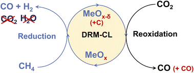
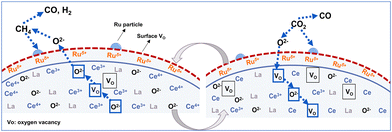
Catalytic chemical looping (CL) is a promising method for improving conventional DRM. As presented in Fig. 1, DRM–CL can be accomplished using metal oxides (MOx) acting as oxygen carriers, which gives out lattice oxygen continuously during the reduction step via partial oxidation of CH4 reaction (POM; eqn (5)) and the lattice oxygen vacancy is refilled during the reoxidation step via CO2 splitting reaction (CS; eqn (6)).
| POM: MOx + δCH4 → MOx−δ + δCO + 2δH2 | (5) |
| CO2 splitting: MOx−δ + δCO2 → MOx + δCO | (6) |
This process remains consistent with the catalytic DRM as a total, even though it involves two distinct gas–solid reactions. Although the overall process would still exhibit its inherent endothermic nature, using chemical looping presents several benefits that are not available when using conventional DRM. First, deactivation by carbon deposition is mitigated because the deposited carbon can be converted by CO2via the reverse Boudouard reaction (eqn (4)), yielding additional CO during the oxidation step. Moreover, the RWGS side reaction is averted because the produced H2 is inherently separated from CO2. Furthermore, the operational conditions can be individually optimised, leading to enhanced performance in specific instances because of the decoupling of reactions.
Selecting suitable oxygen carriers plays a crucially role in the DRM–CL process. However, this approach still presents several difficulties that must be addressed. First, syngas selectivity is diminished because of the presence of CO2 or H2O resulting from the total oxidation of methane (eqn (7)). Second, earlier-reported oxygen carriers require high operating temperatures (>1073 K), presenting an obstacle to their integration with downstream low-temperature processes such as Fischer–Tropsch (F–T) synthesis.4 This limitation also hinders using various cost-effective industrial materials (e.g., stainless steel and so on) with lower melting points or recycled industrial waste heat.5
| Total oxidation of methane: CH4 + MOx → CO2 + H2O + MOx−δ | (7) |
| Methane pyrolysis: CH4(+M) → 2H2 + C(s)(+M) | (8) |
The primary hindrance to the reactivity in POM, particularly at lower temperatures, is the great amount of activation energy needed for lattice oxygen migration and removal. Furthermore, syngas selectivity is contingent on the type and abundance of surface oxygen species. Syngas selectivity is also influenced by the relative rates of bulk and subsurface oxygen conduction and surface oxygen reaction during the redox reactions. Moreover, the conduction of bulk and subsurface lattice oxygen to the oxide surface imposes limitations on the overall redox conversion.6–8 Ce-based materials are highly appealing in DRM–CL because of their oxygen mobility and storage capacity.9–12 From a thermodynamic perspective, the oxidation of reduced ceria by CO2 is favourable across a wide temperature range, from 298 K to over 1273 K.13 Additionally, reduction from CeO2 to Ce6O11 has been observed by Otsuka et al.14 as occurring at temperatures as low as 923 K, which is consistent with thermodynamic calculations. Doping metals into CeO2 is an effective strategy for enhancing the reduction of Ce4+ to Ce3+.15,16 Reportedly, La2Ce2O7 (denoted LCO) prepared by introducing lanthanum (La) into CeO2 can create a synergistic effect, leading to high stability and high oxygen-ionic conductivity.17–20 Furthermore, Ru metal is selected as the promoter because it is highly effective for methane activation, with high selectivity towards syngas, as reported in conventional DRM. It is also less expensive than other noble metals.21,22 Therefore, we propose an investigation of the performance and properties of Ru/LCO as oxygen carriers for DRM–CL reaction.
As demonstrated by this study, loading small amounts of Ru (0.5 or 1 wt%) to LCO oxygen carrier can activate CH4 even at a low temperature of approximately 545 K. The 1 wt% Ru/La2Ce2O7 material exhibits remarkable performance, achieving CH4 conversion around 65%, with minimal CO2 produced during the reduction step and CO2 conversion exceeding 95% during the re-oxidation step at 923 K over 10 redox cycles. Despite a slight occurrence of carbon deposition during the reduction step, the redox performance remains stable over many cycles because of the efficient conversion of deposited carbon during the oxidation step and the inherent stability of the oxygen carriers. This improvement enables the broader application of DRM–CL, leading to considerable energy and cost savings. The exceptional performance is attributed to forming strong metal–support interaction (SMSI) between Ru and LCO, forming Ru–O–Ce bonds at the Ruδ+–CeO2−x interface. This interaction anchors active Ru components onto stable LCO with excellent ionic conductivity, enhancing methane activation by reducing the energy barrier through increased surface oxygen vacancies and maintaining structural stability with highly dispersed Ru promoters during many cycles. Moreover, the migration of O2− in subsurface is promoted by creating an elevated oxygen chemical potential gradient induced by the oxygen-deprived surface facilitated by the Ru promoter.
Results and discussion
Screening of xRu/LCO catalysis-oxygen carrier
Fig. 2 shows the effect of the loading amount of Ru promoter on the redox performance of xRu/LCO as investigated using CH4-TPR and isothermal redox experiments. Fig. 2A shows that only a small amount of Ru promoter can improve the CH4 activation ability of LCO efficiently, presenting lower CH4 activation onset temperatures at around 545 K. Furthermore, LCO exhibits a lower CH4 activation onset temperature of 731 K than that of CeO2, with an almost complete CO peak at around 1173 K, but no complete peak for CeO2 even at temperatures higher than 1273 K, which indicates that the doping of La improves the CH4 activation ability of CeO2. Moreover, a lower loading amount of Ru promoter results in a lower temperature for the peak amount for CO production, indicating that low loading amounts as 0.5 or 1 wt% Ru promoter are able to activate CH4 toward syngas with superior performance. Therefore, xRu/LCO exhibits promise for DRM–CL because of its capability to generate substantial oxygen vacancies at low temperatures (ca. 545 K) through reaction with CH4.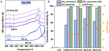 | ||
| Fig. 2 (A) CH4-TPR of xRu/LCO and CeO2; (B) CH4 conversion, CO selectivity during the reduction step and CO2 conversion during the reoxidation step of xRu/LCO at 923 K. | ||
Regarding performance during the reduction step at 923 K in Fig. 2B, all Ru-promoted samples exhibit CO selectivity exceeding 95% and CH4 conversion surpassing 50%. However, the performance results show that LCO remains almost inert for CH4 at 923 K without Ru promoter, highlighting the key role of Ru on CH4 activation. Most notably, CH4 conversion shows a volcanic shape with a maximum value of 70% when the loading amount is 3 wt%. The carbon deposition characterised by H2/CO ratio also shows a volcanic shape with the most severe carbon deposition (H2/CO = 5.5) occurring when the loading amount is 3 wt%. A possible reason for these results is the following: When the loading amount of Ru promoter is less than 3 wt%, the CH4 activation is enhanced with the increased amount of Ru promoter. However, as shown in Table S1,† a loading amount of Ru promoter that is greater than 3 wt% leads to a larger mean particle size (obtained by XRD) and a smaller surface area (obtained by BET). Consequently, the active Ru promoters cannot be fully exposed to the oxygen carrier surface to activate CH4. Regarding performance in the CO2 reoxidation step, nearly 100% CO2 conversion was achieved for all Ru-promoted samples. Above all, the findings indicate that satisfactory conversion and high selectivity can be attained at 923 K using very low-load Ru (0.5 or 1 wt%). Furthermore, considering the detection limit of characterisation instruments, 1Ru/LCO instead of 0.5Ru/LCO should be selected for additional study to obtain more precise surface characterisation results, although x = 0.5 already shows satisfactory performance results at 923 K.
Redox performance of 1Ru/LCO at different temperatures
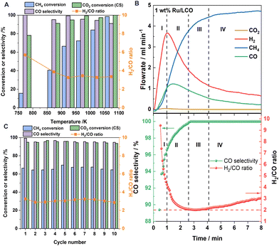
Fig. 3A shows the redox performance of 1Ru/LCO during isothermal DRM–CL at various temperatures. 1Ru/LCO exhibits methane conversion of 16% at temperatures as low as 773 K, and it reaches almost 100% when temperatures rise to 1073 K. Regarding the carbon deposition characterised by H2/CO ratio, it decreases as temperatures rise at temperatures lower than 923 K, but it reaches a stable value of approximately 3 at 923–1073 K. Although it is higher than the ideal value of 2, indicating the appearance of carbon deposition, it was verified later that all the carbon produced can be converted into additional CO via the reverse Boudouard reaction during the CO2 reoxidation step, resulting in zero net coke formation during DRM–CL. Furthermore, 1Ru/LCO shows CO selectivity higher than 90% within 773–1073 K, indicating a highly selective surface for the production of CO instead of CO2. Moreover, excellent CO2 conversion of 78% at temperatures as low as 773 K and conversion approaching 100% over 973 K is obtained on 1Ru/LCO during the CO2 reoxidation step. Above all, based on a comprehensive consideration of the temperature, conversion rate and selectivity, a standard operation temperature of 923 K should be selected for the following isothermal redox performance evaluations.Kinetic profiles
Fig. 3B shows that profiles of H2 concentrations increase remarkably followed a little later by CO concentrations, with negligible CO2 produced when CH4 is introduced. According to the corresponding calculated H2/CO ratio and CO selectivity, the reaction progress is divisible into four consecutive regions according to the H2/CO ratio and CO selectivity. During the initial period (region I), the remaining active surface oxygen species after H2 pretreatment leads to total methane oxidation reaction and good catalytic performance of Ru metal for methane decomposition causing the carbon deposition. After gradual consumption of the surface oxygen species, the subsurface oxygen species can partially oxidise methane to CO and H2 (region III). A transition region (region II) is predominant between region I and region III. When oxygen species are consumed further, the region of carbon formation dominates by methane decomposition (region IV). Therefore, the carbon deposition can be alleviated efficiently by controlling the reaction time of the reduction step with CH4.Stability test
The long-term stability of 1Ru/LCO was studied by gas phase detection in the successive 10 redox cycles at 923 K, as portrayed in Fig. 3C. The 1Ru/LCO sample shows high CH4 conversion around 65% with almost no CO2 produced in the reduction step and CO2 conversion exceeding 95% for CS reaction in the reoxidation step at 923 K over 10 redox cycles. Although the H2/CO ratio remains at around 3, the redox performance remains stable over cycles, demonstrating that the deposited carbon can be well converted during the oxidation step, indicating that the oxygen carrier is well regenerated, and showing that the structure remains stable over many cycles, as confirmed later from XRD and STEM findings. As shown in Fig. S2,† the CO yield in the CS reaction is twice that of the POM reaction. Therefore, the final H2/CO ratio can be adjusted easily to different values as necessary using the CO produced in the reoxidation step.To elucidate the state of carbon deposition during redox cycles, 10 redox cycle tests were also conducted using a thermal gravimetric analyser (TGA) by detecting the solid phase for visually observing the weight change caused by the change of carbon deposition. As presented in Fig. 4A, when flowing in CH4, the weight of the oxygen carrier promptly decreases because of the migration of the lattice oxygen for the POM reaction. Then it increases slowly because of carbon deposition. Afterwards, when flowing in CO2, it drastically increases to the maximum, first because of the refilling of lattice oxygen. Thereafter, it starts to decrease because of the consumption of the carbon deposited (marked in green) during the reoxidation step. The redox amount of lattice oxygen and the decrease carbon weight during each cycle are calculated and presented in Fig. 4B. A large weight of consumed carbon and a higher oxidation amount than the reduction amount, were observed in cycle 1. After that, the consumed carbon weight during the oxidation step generally decreases along with the number of cycles before being stabilised from cycle 6, because 10 min oxidation by CO2 is insufficient to remove the high carbon amount completely from cycle 1, leading to carbon accumulation, which is removed with cycles and stabilised because of the lesser amounts of produced carbon during cycles after cycle 1. Accordingly, the redox amount stabilises from cycle 5 with the removal of accumulated carbon from the first cycles, indicating that good stability of 1Ru/LCO is obtainable even with a longer reaction time because of the successful removal of carbon by CO2.
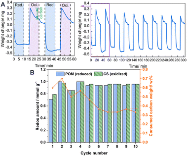 | ||
| Fig. 4 (A) TGA of 1Ru/LCO during 10-cycle redox tests performed in alternating CH4 and CO2 flow. (B) Calculated data from the TGA profile. | ||
Characterisations – structural and micromorphological evolution
Fig. 5A depicts the XRD patterns of the CeO2, LCO, and 1Ru-promoted LCO samples: as-made, after reduction, after oxidation, and after 10 cycles. Only a simple pattern ascribed to the fluorite structure of CeO2 was observed, with no extra diffraction phases. This lack of extra diffraction phases illustrates that the fluorite structure of CeO2 is maintained after La substitution or Ru loading. The diffraction peaks of LCO shift towards lower degrees compared to those of CeO2. This shift results from the incorporation of La3+ into the lattice of CeO2, leading to an increase in lattice parameters because of the augmented number of oxygen vacancies and the larger cation diameter of La3+. The mean size of CeO2 is markedly smaller after La doping. There is no observable peak ascribable to Ru in xRu/LCO in Fig. S3,† indicating that Ru is highly dispersed and that no phase separation occurs within 5 wt% loading amounts. It is noteworthy that no readily apparent shift or observable peak ascribable to Ru is observed between the diffraction peaks of the reduced, oxidised, and 10-cycled 1Ru/LCO samples, indicating that the 1Ru/LCO retains structural stability with Ru highly dispersed during 10 successive DRM–CL redox cycles. Moreover, as Table 1 shows, the mean size of 1Ru/LCO remained stable without remarkable change after reduction, oxidation, or even 10 cycles. This stability might be related to the formation of strong Ru–O–Ce bonds at the Ruδ+–CeO2−x interface, as confirmed by XPS results described hereinafter.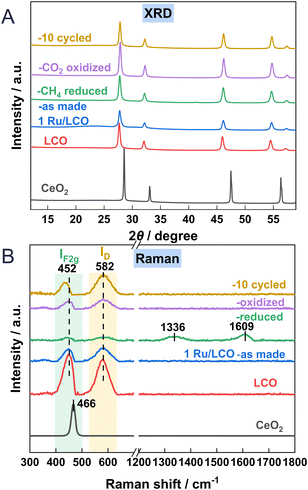 | ||
| Fig. 5 (A) XRD patterns and (B) Raman profiles of CeO2, LCO, 1Ru/LCO (as made, reduced, oxidised and 10 cycled) samples. | ||
| Sample | S BET (m2 g−1) | Mean sizeb (nm) | I D/IF2gc |
|---|---|---|---|
| a Determined by the BET method. b Estimated by the Scherrer equation based on the reflection of CeO2. c Calculated from the Raman results. | |||
| LCO | 20.8 | 0.88 | |
| 1Ru/LCO-as made | 11.2 | 20.7 | 1.10 |
| 1Ru/LCO-reduced | 13.2 | 19.2 | 1.37 |
| 1Ru/LCO-oxidised | 11.5 | 22.4 | 1.31 |
| 1Ru/LCO-10 cycled | 7.3 | 23.8 | 1.67 |
Raman spectroscopy was used to elucidate the oxygen vacancies formation in CeO2 lattice. Fig. 5B shows Raman spectra of CeO2, LCO, 1Ru/LCO, and 1Ru/LCO during/after DRM–CL cycle samples. Strong peaks at approx. 452 cm−1 attributed to the F2g vibration mode of the Ce–O bond, are observed on all samples. Moreover, an additional peak at approx. 582 cm−1 attributed to defect-induced (D) modes of the fluorite phase23,24 was observed for samples related to LCO, indicating that the doping of La induces the appearance of the subsurface oxygen vacancies. Moreover, the ratios of ID/IF2g, indicating the relative concentrations of oxygen vacancies in CeO2 lattice, are presented in Table 1. The higher ID/IF2g ratio in 1Ru/LCO compared to that in LCO indicates that the introduction of a small amount of Ru promoter enhances the formation of oxygen vacancies effectively. This enhancement is likely to be attributable to the formation of a strong Ru–O–Ce bond at the Ruδ+–CeO2−x interface, as confirmed hereinafter based on XPS and in situ CO-DRIFTS results. The existing literature acknowledges that oxygen vacancies play a crucially important role in facilitating CH4 activation by reducing the dissociation barriers of CH3, CH2, and CH radicals.25
Moreover, the ID/IF2g ratio of 1Ru/LCO greatly increases after reduction and decreases slightly after oxidation because the lattice oxygen was released in the reduction step and was refilled in the re-oxidation step. Two peaks at 1336 and 1609 cm−1 attributed to carbon species were observed after reduction, but they disappeared during re-oxidation,26,27 indicating that carbon deposited during the reduction step can be consumed by CO2 during the oxidation step. It is noteworthy that 1Ru/LCO shows a much higher the ID/IF2g ratio than after first oxidation after 10 cycles because more lattice oxygen is involved with reduction by CH4 for 10 times.
The STEM, EDS element mappings, and high-resolution STEM results obtained for the fresh, reduced, and oxidised 1Ru/LCO are depicted in Fig. 6, whereas those for the 10 cycled 1Ru/LCO are presented in Fig. S4.† The STEM images revealed that the particle size of 1Ru/LCO remains consistent at 20–30 nm throughout the entire DRM–CL process, even after 10 cycles (consistent with mean size results calculated from XRD in Table 1), further confirming the structural stability of 1Ru/LCO. However, the CO pulse experiment revealed a mean diameter of Ru metal at 265.6 nm, which deviates considerably from results obtained using STEM and XRD. This disparity can be attributed to the formation of surface Ruδ+ resulting from SMSI effects between Ru and La2Ce2O7. This formation decreases the amount of CO adsorption on the surface Ru metal and engenders inaccurate results for the Ru particle size. This observation indirectly underscores the presence of SMSI in the system. Moreover, high-resolution STEM images show that only two lattice fringes corresponding to (111) and (200) of CeO2 are detected in the samples of fresh, reduced, oxidised, and 10 cycled 1Ru/LCO.28,29 This single-phase of CeO2 with the apparent absence of La and Ru particles suggests that La particles are well incorporated into the crystalline phase of CeO2, whereas Ru components exist as highly dispersed RuOx species over the LCO, aligning with XRD results. Of paramount importance is that the results of EDS element mappings demonstrate that all elements, especially Ru, maintain high dispersion throughout the entire DRM–CL process, even after 10 cycles. No aggregation is observed, reflecting that Ru particles are anchored on the stable LCO support through the strong Ru–O–Ce bond at the Ruδ+–CeO2−x interface, ensuring high stability.
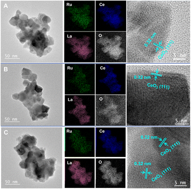 | ||
| Fig. 6 STEM images, EDS element mappings and high-resolution STEM images of 1Ru/LCO (A) fresh, (B) CH4 reduced, (C) CO2 re-oxidised samples. | ||
Surface chemistry
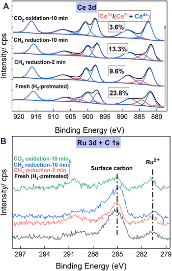
As illustrated in Fig. 7A, the XPS Ce 3d spectra exhibit five pairs of 3d5/2 and 3d3/2 characteristic peaks. Three pairs, with peaks at 881.7, 887.9, and 897.2 eV, each accompanied by peaks at 900.1, 906.6, and 916.8 eV, are attributed to Ce4+ species, whereas the remaining two pairs are associated with Ce3+ species (some peaks with nearly zero area values appear as a result of fitting optimisation).30,31 The Ce3+ ratio, calculated using the peak areas of Ce3+/(Ce3+ + Ce4+), is an important indicator of the oxygen vacancies on ceria surfaces.32,33 It is noteworthy that the Ce3+ ratio of the samples after CH4 reduction at 923 K is markedly lower than that of the fresh sample, pretreated with H2 at 673 K for 30 min. This finding is likely attributable to the heating process from 673 K to 923 K, which accelerates the diffusion of oxide ions inside the oxygen carrier material. Consequently, the oxygen vacancies become more homogeneously distributed in the surface and subsurface layers, potentially resulting in a relative reduction in the surface Ce3+ ratio. Moreover, the Ce3+ ratio increases consistently from 9.6% to 13.3% with CH4 reduction from 2 min to 10 min, indicating augmentation in oxygen vacancies on ceria surfaces resulting from the POM reaction through the reduction of Ce4+ to Ce3+. Subsequently, the Ce3+ ratio decreases markedly to 3.6% after 10 min of CO2 reoxidation, indicating the efficient refilling of surface oxygen vacancies through the oxidation of Ce3+ to Ce4+.In the XPS spectra of C 1s + Ru 3d (Fig. 7B), the Ru 3d5/2 is commonly used to understand the charge state of Ru species because of the overlapping of Ru 3d3/2 and C 1s peak at approximately the 284.8 eV position. Throughout the entire redox process, peaks attributed to partially charged Ru nano particles (Ruδ+) at around 280.8 eV position are observed. This phenomenon is associated with charge transfer during the formation of the Ru–O–Ce species, contributing to the enhancement of oxygen vacancies. Similar observations have been reported widely for other ceria-supported Ru systems. Liu et al.10 reported that the Ru nanoparticles supported on ceria with Ruδ+ and O decoration exhibit much better stability than those with only metallic Ru0 under steady-state DRM conditions because of their sustained active chemistry. Furthermore, earlier theoretical investigations into the activation of methane over CeO2-supported transition metals suggested that strong interaction between the metal and ceria support and acquisition of positive charges constitute markedly lower methane activation barriers.25,34,35
Simultaneously, the spectra and quantitative results presented in Table 2 reveal continuous accumulation of surface carbon (approx. 284.9 eV) attributable to methane decomposition during the reduction by CH4 from 2 to 10 min. This carbon accumulation decreases considerably to levels lower than those after 2 min of CH4 reduction following 10 min of CO2 reoxidation. This decrease further confirms the consumption of deposited carbon during CO2 reoxidation, which is consistent with results obtained from Raman and TGA analyses.
| Sample | Ce | La | O/atom% | C | Ru |
|---|---|---|---|---|---|
| H2 treatment | 9.7 | 13.0 | 53.7 | 23.4 | 0.2 |
| CH4 2 min | 10.5 | 14.0 | 57.2 | 18.1 | 0.2 |
| CH4 10 min | 9.8 | 12.8 | 53.8 | 23.5 | 0.1 |
| CO2 10 min | 10.8 | 14.8 | 61.3 | 12.9 | 0.2 |
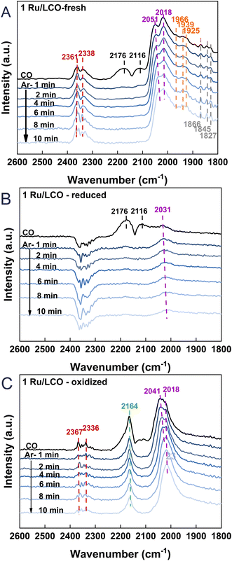
To gain additional insights into the surface adsorption condition changes occurring during the DRM–CL process of 1Ru/LCO, in situ CO-adsorption DRIFTS was performed for the fresh, reduced, and oxidised 1Ru/LCO. The results are presented in Fig. 8. Upon the fresh 1Ru/LCO surface in Fig. 8A, IR bands at 2176 and 2116 cm−1, attributed to gaseous CO, disappear rapidly after 1 min Ar purging. Additionally, bands at 1866, 1845, and 1827 cm−1 correlated with bridge-bound CO adsorption on Ru atoms are observed along with two prominent bands at 2051 and 2018 cm−1 assigned to linearly absorbed CO on Ru atoms,36–38 showing that Ru species are well-dispersed on the surface. It is noteworthy that bands are visible at 1966, 1939, and 1925 cm−1, corresponding to CO adsorption on the interface of the Ru metal and LCO support.39,40 These further validate the XPS results, indicating interactions between the LCO support and Ru clusters. On the reduced 1Ru/LCO surface in Fig. 8B, except for the quickly disappearing bands attributed to gaseous CO, only one band associated with absorbed CO on Ru atoms remains, resulting from the surface partially covered by carbon deposited from CH4 decomposition. On the oxidised sample surface in Fig. 8C, bands related to Ru metal atoms reappear, suggesting that CO2 reoxidation removes deposited carbon effectively, thereby uncovering the surface and regenerating the adsorption sites of the material for the next cycle. Additionally, a distinctive band is apparent at 2164 cm−1, attributed to CO adsorbed onto Ce4+ cations with different unsaturated coordination.41–43 That band constitutes evidence for the completion of oxygen vacancy refilling and oxygen migration from the subsurface to the surface during the transition from Ce3+ to Ce4+. Importantly, IR bands at 2361 and 2338 cm−1 positions, attributed to linearly or physically adsorbed CO2,26,44 resulting from the reaction between CO adsorbed onto surface oxygen vacancies and oxygen species, were observed on both fresh and oxidised sample surfaces. Those bands reflect an abundance of surface oxygen vacancies for CH4 activation, related to the strong interaction through the formation of Ru–O–Ce. This interaction endures even after cycling, demonstrating the remarkable stability of 1Ru/LCO.
Discussion
Based on analyses of structural and electronic properties, the proposed reaction processes of DRM–CL over 1Ru/LCO oxygen carrier are presented in Fig. 9. Specifically, in the reduction step, the activated CH4 releases the lattice oxygen through the transition from Ce4+ to Ce3+, with the formation of oxygen vacancies. Then in the oxidation step, CO2 is adsorbed and dissociated on the surface of 1Ru/LCO oxygen carrier with progress of the oxidation step, thereby re-filling the oxygen vacancies. This sequence is repeated iteratively, completing each redox cycle. The presence of surface Ruδ+ plays a crucially important role in enhancing the performance of both the oxidation and reduction steps and contributing to the overall cyclic stability.The CH4-TPR and redox performance presented in Fig. 2 and 3 demonstrate the remarkable efficiency of a small amount of 0.5 or 1 wt% Ru promoter for enhancing the CH4 activation ability of LCO. This enhancement leads to a low CH4 activation onset temperature of approximately 545 K, achieving approximately 65% CH4 conversion, even at 723 K. Raman (Fig. 5B), XPS (Fig. 7), and in situ CO-adsorption DRIFTS (Fig. 8) results emphasise the fundamentally important role played by oxygen vacancies and the Ru–O–Ce bond formed because of SMSI in supporting the superior CH4 reactivity. The formation of Ru–O–Ce bonds at the RuOx–CeO2−x interface, as supported by density functional theory calculations45 and experiments,46 decreases the oxygen vacancy formation energy, consequently improving low-temperature CH4 reactivity. Moreover, the well-dispersed Ruδ+ species in the form of Ru−O−Ce bonds contribute to mobile and active oxygen ions for DRM–CL processes.
The performance results presented in Fig. 3 also show CO2 conversion greater than 95% at 723 K in the CO2 reoxidation step. Earlier studies of surface-promoted oxygen carriers highlight the importance of the potential gradient between the oxide bulk (or subsurface) and surface induced by the prompted surface for O2− migration.8 In our case, the oxygen-deprived surface in the presence of Ru establishes an increased oxygen chemical potential gradient between the oxide subsurface and surface. This enhancement engenders improved O2− migration, facilitated by the redox reaction between Ce3+ and Ce4+ in the subsurface of the oxygen carrier, ultimately completing the chemical looping process and promoting CO2 conversion.
Cycle stability tests for the gas phase demonstrate excellent redox performance over 10 cycles (Fig. 3C and 4A), with observation of the removal of the deposited carbon in the reoxidation step by TGA (Fig. 4), Raman (Fig. 5B and Table 1), and XPS (Fig. 6 and Table 2). Additionally, XRD (Fig. 6A), BET (Table 1), and STEM-EDS (Fig. 6) findings demonstrate that the structure of 1Ru/LCO remains stable after 10 cycles, with Ru maintaining a highly dispersed state. This state is attributed to the formation of Ru–O–Ce bonds anchoring active Ru onto stable La2Ce2O7 with excellent ionic conductivity, highlighting its strong anti-aggregation capability.
Conclusions
Ru/La2Ce2O7 catalytic chemical looping material is highly effective for enhancing CH4 activation even at low temperatures (545 K). The 1 wt% Ru/LCO demonstrates remarkable performance, achieving CH4 conversion of approximately 65%, with minimal CO2 production during the reduction step and CO2 conversion exceeding 95% during the CO2 re-oxidation step at 923 K over 10 redox cycles. Despite encountering slight carbon deposition during the reduction step, the redox performance maintains stability in 10 successive cycles because of the efficient carbon conversion which occurs during the reoxidation step and because of the inherent structure stability of the oxygen carrier. This exceptional performance is attributed to the establishment of a strong metal–support interaction between Ru and La2Ce2O7, forming crucially important Ru–O–Ce bonds. These bonds anchor the active Ru species onto the stable and ionic conductive La2Ce2O7 substrate. This mechanism enhances CH4 activation by increasing surface oxygen vacancies. Moreover, it maintains structural stability with well-dispersed Ru promoters throughout the cyclic process. Furthermore, the oxygen-deprived surface induced by Ru presence creates an elevated oxygen chemical potential gradient between the oxide subsurface and surface, improving O2− migration for the redox reaction between Ce3+ and Ce4+ in the subsurface of the oxygen carrier to accomplish the chemical looping process effectively.Author contributions
Conceptualisation: KK and YS, funding acquisition: YS, investigation: KK, NK, CS, project administration: YS, supervision: YS, validation: KK, NK, TH, CS, YS, visualization: KK, writing – original draft: KK, writing – review & editing: YS.Conflicts of interest
There are no conflicts to declare.Acknowledgements
Equipment (JEM-2100F: Material Characterization Central Laboratory in Waseda University) shared with the MEXT Project for Promoting Public Utilization of Advanced Research Infrastructure (Program for supporting the construction of core facilities) under grant numbers JPMXS0440500022, and JPMXS0440500023 was used. A part of this work was supported by JST-ALCA-Next Program Grant Number 23836167, Japan, and International Leading Research (grant no. 23K20034) from the Japan Society for the Promotion of Science, Japan. The author acknowledges the financial support from the China Scholarship Council (Grant No. 202104910057).References
- N. A. K. Aramouni, J. G. Touma, B. A. Tarboush, J. Zeaiter and M. N. Ahmad, Renewable Sustainable Energy Rev., 2018, 82, 2570–2585 CrossRef CAS.
- M. Usman, W. M. A. Wan Daud and H. F. Abbas, Renewable Sustainable Energy Rev., 2015, 45, 710–744 CrossRef CAS.
- J. Wei and E. Iglesia, Angew. Chem., Int. Ed., 2004, 43, 3685–3688 CrossRef CAS PubMed.
- Q. Zhang, W. Deng and Y. Wang, J. Energy Chem., 2013, 22, 27–38 CrossRef CAS.
- A. Shafiefarhood, N. Galinsky, Y. Huang, Y. G. Chen and F. X. Li, ChemCatChem, 2014, 6, 790–799 CrossRef CAS.
- A. Shafiefarhood, J. C. Hamill, L. M. Neal and F. Li, Phys. Chem. Chem. Phys., 2015, 17, 31297–31307 RSC.
- L. M. Neal, A. Shafiefarhood and F. Li, ACS Catal., 2014, 4, 3560–3569 CrossRef CAS.
- A. Shafiefarhood, J. Zhang, L. M. Neal and F. Li, J. Mater. Chem. A, 2017, 5, 11930–11939 RSC.
- Z. Liu, D. C. Grinter, P. G. Lustemberg, T.-D. Nguyen-Phan, Y. Zhou, S. Luo, I. Waluyo, E. J. Crumlin, D. J. Stacchiola, J. Zhou, J. Carrasco, H. F. Busnengo, M. V. Ganduglia-Pirovano, S. D. Senanayake and J. A. Rodriguez, Angew. Chem., Int. Ed., 2016, 55, 7455–7459 CrossRef CAS PubMed.
- Z. Liu, F. Zhang, N. Rui, X. Li, L. Lin, L. E. Betancourt, D. Su, W. Xu, J. Cen, K. Attenkofer, H. Idriss, J. A. Rodriguez and S. D. Senanayake, ACS Catal., 2019, 9, 3349–3359 CrossRef CAS.
- S. Miyazaki, Z. Li, Z. Maeno, T. Toyao, M. Ito, Y. Nakajima and K.-I. Shimizu, Chem. Lett., 2022, 51, 914–918 CrossRef CAS.
- K. Otsuka, Y. Wang, E. Sunada and I. Yamanaka, J. Catal., 1998, 175, 152–160 CrossRef CAS.
- S. Assabumrungrat, S. Charoenseri, N. Laosiripojana, W. Kiatkittipong and P. Praserthdam, Int. J. Hydrogen Energy, 2009, 34, 6211–6220 CrossRef CAS.
- K. Otsuka, Y. Wang, E. Sunada and I. Yamanaka, J. Catal., 1998, 175, 152–160 CrossRef CAS.
- F. R. García-García and I. S. Metcalfe, Catal. Commun., 2021, 160, 106356 CrossRef.
- J. Guerrero-Caballero, T. Kane, N. Haidar, L. Jalowiecki-Duhamel and A. Löfberg, Catal. Today, 2019, 333, 251–258 CrossRef CAS.
- M. Tang, K. Liu, D. M. Roddick and M. Fan, J. Catal., 2018, 368, 38–52 CrossRef CAS.
- B. Choudhary, L. Besra, S. Anwar and S. Anwar, Int. J. Hydrogen Energy, 2023, 48, 28460–28501 CrossRef CAS.
- Q. Zhang, X. Zheng, J. Jiang and W. Liu, J. Phys. Chem. C, 2013, 117, 20379–20386 CrossRef CAS.
- A. P. Ramon, X. Li, A. H. Clark, O. V. Safonova, F. C. Marcos, E. M. Assaf, J. A. van Bokhoven, L. Artiglia and J. M. Assaf, Appl. Catal., B, 2022, 315, 121528 CrossRef CAS.
- P. Ferreira-Aparicio, C. Márquez-Alvarez, I. Rodríguez-Ramos, Y. Schuurman, A. Guerrero-Ruiz and C. Mirodatos, J. Catal., 1999, 184, 202–212 CrossRef CAS.
- A. J. Carrillo, L. Navarrete, M. Laqdiem, M. Balaguer and J. M. Serra, Adv. Mater., 2021, 2, 2924–2934 RSC.
- Z. Xu, H. Tian, A. Khanaki, R. Zheng, M. Suja and J. Liu, Sci. Rep., 2017, 7, 43100 CrossRef CAS PubMed.
- C. Zheng, D. Mao, Z. Xu and S. Zheng, J. Catal., 2022, 411, 122–134 CrossRef CAS.
- Z. Cheng, L. Qin, M. Guo, J. A. Fan, D. Xu and L.-S. Fan, Phys. Chem. Chem. Phys., 2016, 18, 16423–16435 RSC.
- Z. Cao, X. Zhu, K. Li, Y. Wei, F. He and H. Wang, Chem. Eng. J., 2020, 397, 125393 CrossRef CAS.
- Y. Han, M. Tian, C. Wang, Y. Kang, L. Kang, Y. Su, C. Huang, T. Zong, J. Lin, B. Hou, X. Pan and X. Wang, ACS Sustainable Chem. Eng., 2021, 9, 17276–17288 CrossRef CAS.
- K. Kang, X. Yao, J. Cao, Z. Li, J. Rong, W. Luo, W. Zhao and Y. Chen, J. Hazard. Mater., 2021, 402, 123551 CrossRef CAS PubMed.
- Z. Zhang, Y. Wang, M. Wang, J. Lü, L. Li, Z. Zhang, M. Li, J. Jiang and F. Wang, Chin. J. Catal., 2015, 36, 1623–1630 CrossRef CAS.
- M. Romeo, K. Bak, J. El Fallah, F. Le Normand and L. Hilaire, Surf. Interfaces, 1993, 20, 508–512 CrossRef CAS.
- B. Lin, Y. Liu, L. Heng, X. Wang, J. Ni, J. Lin and L. Jiang, Ind. Eng. Chem. Res., 2018, 57, 9127–9135 CrossRef CAS.
- H. Huang, Q. Dai and X. Wang, Appl. Catal., B, 2014, 158–159, 96–105 CrossRef CAS.
- N. Wang, W. Qian, W. Chu and F. Wei, Catal. Sci. Technol., 2016, 6, 3594–3605 RSC.
- Z. Liu, P. Lustemberg, R. A. Gutiérrez, J. J. Carey, R. M. Palomino, M. Vorokhta, D. C. Grinter, P. J. Ramírez, V. Matolín, M. Nolan, M. V. Ganduglia-Pirovano, S. D. Senanayake and J. A. Rodriguez, Angew. Chem., Int. Ed., 2017, 56, 13041–13046 CrossRef CAS PubMed.
- P. G. Lustemberg, P. J. Ramírez, Z. Liu, R. A. Gutiérrez, D. G. Grinter, J. Carrasco, S. D. Senanayake, J. A. Rodriguez and M. V. Ganduglia-Pirovano, ACS Catal., 2016, 6, 8184–8191 CrossRef CAS.
- D. Yubero Valdivielso, C. Kerpal, W. Schöllkopf, G. Meijer and A. Fielicke, Dalton Trans., 2023, 52, 9929–9939 RSC.
- J. Li, Z. Liu, D. A. Cullen, W. Hu, J. Huang, L. Yao, Z. Peng, P. Liao and R. Wang, ACS Catal., 2019, 9, 11088–11103 CrossRef CAS.
- G. H. Yokomizo, C. Louis and A. T. Bell, J. Catal., 1989, 120, 1–14 CrossRef CAS.
- O. Pozdnyakova, D. Teschner, A. Wootsch, J. Kröhnert, B. Steinhauer, H. Sauer, L. Toth, F. C. Jentoft, A. Knop-Gericke, Z. Paál and R. Schlögl, J. Catal., 2006, 237, 1–16 CrossRef CAS.
- P. Bazin, O. Saur, J. C. Lavalley, M. Daturi and G. Blanchard, Phys. Chem. Chem. Phys., 2005, 7, 187–194 RSC.
- C. Binet, M. Daturi and J.-C. Lavalley, Catal. Today, 1999, 50, 207–225 CrossRef CAS.
- A. Badri, C. Binet and J.-C. Lavalley, J. Chem. Soc., Faraday Trans., 1996, 92, 4669–4673 RSC.
- M. I. Zaki, B. Vielhaber and H. Knoezinger, J. Phys. Chem., 1986, 90, 3176–3183 CrossRef CAS.
- G. Deng, G. Zhang, X. Zhu, Q. Guo, X. Liao, X. Chen and K. Li, Appl. Catal., B, 2021, 289, 120033 CrossRef CAS.
- H.-T. Chen, J. Phys. Chem. C, 2012, 116, 6239–6246 CrossRef CAS.
- M. Kurnatowska, W. Mista, P. Mazur and L. Kepinski, Appl. Catal., B, 2014, 148–149, 123–135 CrossRef CAS.
Footnote |
| † Electronic supplementary information (ESI) available. See DOI: https://doi.org/10.1039/d4cy00450g |
| This journal is © The Royal Society of Chemistry 2024 |

