ZnFe2O4 nanosheet array: a highly efficient electrocatalyst for ambient ammonia production via nitrite reduction†
Chenggang
Xu‡
*a,
Yimei
Liang‡
ab,
Xun
He
 b,
Ailin
Zhang
ab,
Ling
Ouyang
b,
Long
Hu
b,
Xiaoya
Fan
b,
Yongsong
Luo
c,
Dongdong
Zheng
c,
Shengjun
Sun
c,
Asmaa
Farouk
d,
Mohamed S.
Hamdy
d and
Xuping
Sun
b,
Ailin
Zhang
ab,
Ling
Ouyang
b,
Long
Hu
b,
Xiaoya
Fan
b,
Yongsong
Luo
c,
Dongdong
Zheng
c,
Shengjun
Sun
c,
Asmaa
Farouk
d,
Mohamed S.
Hamdy
d and
Xuping
Sun
 *bc
*bc
aCollege of Chemical and Materials Science, Sichuan Normal University, Chengdu 610068, Sichuan, China. E-mail: xucgg@163.com
bInstitute of Fundamental and Frontier Sciences, University of Electronic Science and Technology of China, Chengdu 610054, Sichuan, China. E-mail: xpsun@uestc.edu.cn
cCollege of Chemistry, Chemical Engineering and Materials Science, Shandong Normal University, Jinan 250014, Shandong, China
dDepartment of Chemistry, College of Science, King Khalid University, Abha 61413, Saudi Arabia
First published on 29th November 2023
Abstract
Electrocatalytic reduction of nitrite (NO2−) offers an eco-friendly and sustainable strategy for synthesizing valuable ammonia (NH3) while simultaneously removing NO2−. Nevertheless, the complexity of the six-electron transfer reaction involved can hamper NH3 production and faradaic efficiency (FE), necessitating the quest for high-performance electrocatalysts. In this study, we introduce ZnFe2O4 nanosheet arrays on nickel foam (ZnFe2O4/NF) as an efficient electrocatalyst for the reduction of NO2− to NH3. ZnFe2O4/NF demonstrates an impressive NH3 yield of 588.58 μmol h−1 cm−2 and a remarkable FE of 95.7% at −0.6 V in 0.1 M NaOH containing 0.1 M NO2−. Furthermore, it exhibits robust stability and durability throughout extended electrolysis and continuous cycling tests.
Ammonia (NH3), an essential chemical widely recognized by human society, finds extensive applications in cosmetics, fertilizers, disinfectants and dyes, and it also holds the potential as a green energy carrier for its remarkable energy density of 4.3 kW h kg−1.1–6 To date, the Haber–Bosch process (HBP) remains the dominant method for ammonia (NH3) synthesis. However, the HBP's demanding production conditions involving high temperatures and pressures have led to significant fossil energy consumption and the release of substantial CO2 emissions. Consequently, there is a pressing need to explore more environmentally friendly approaches to NH3 production. Electrochemical reduction of nitrogen (eNRR) has garnered substantial research interest as a sustainable pathway for the electro-synthesis of NH3.7–11 Nonetheless, the challenging dissociation enthalpy of the N
![[triple bond, length as m-dash]](https://www.rsc.org/images/entities/char_e002.gif) N bond (941 kJ mol−1) and the extremely low solubility of N2, in conjunction with the competition from the hydrogen evolution reaction (HER), pose significant hurdles, leading to less-than-desirable NH3 yield and faradaic efficiency (FE).
N bond (941 kJ mol−1) and the extremely low solubility of N2, in conjunction with the competition from the hydrogen evolution reaction (HER), pose significant hurdles, leading to less-than-desirable NH3 yield and faradaic efficiency (FE).
Fortunately, nitrite (NO2−) offers excellent solubility and significantly lower N![[double bond, length as m-dash]](https://www.rsc.org/images/entities/char_e001.gif) O bond energy (204 kJ mol−1) when compared to N2, which makes the electrochemical nitrite reduction reaction (eNO2−RR) more advantageous than the HBP and electrochemical nitrogen reduction (eNRR) for NH3 production.12–16 Notably, the eNO2−RR not only serves to remove harmful NO2− from industrial wastewater but also generates value-added NH3.17,18 However, the conversion of NO2− to NH3 results in the production of additional by-products (N2H4, H2, and N2), which significantly hinder its selectivity for NH3. Therefore, it has become essential to search for electrocatalysts for the eNO2−RR with high selectivity.
O bond energy (204 kJ mol−1) when compared to N2, which makes the electrochemical nitrite reduction reaction (eNO2−RR) more advantageous than the HBP and electrochemical nitrogen reduction (eNRR) for NH3 production.12–16 Notably, the eNO2−RR not only serves to remove harmful NO2− from industrial wastewater but also generates value-added NH3.17,18 However, the conversion of NO2− to NH3 results in the production of additional by-products (N2H4, H2, and N2), which significantly hinder its selectivity for NH3. Therefore, it has become essential to search for electrocatalysts for the eNO2−RR with high selectivity.
Noble metal-containing materials show promise for the eNO2−RR, however, their high costs and limited availability hinder their practical large-scale application.19,20 In contrast, iron (Fe), which is abundant and cost-effective, serves as the active center in biological enzymes responsible for the reduction of NO2− to NH3.21,22 Recent research has pointed to the activity of Fe and its hybrids in the eNO2−RR.23–27 On the other hand, Fe3O4 has garnered favor in the field of electrocatalysis for its ease of synthesis and excellent electrical conductivity,28–32 making it a promising candidate for eNO2−RR applications. Nevertheless, it's worth noting that Fe3O4 faces a challenge in terms of limited adsorption capacity, and thus, further enhancements are required. Zinc (Zn), ranking as the second most abundant non-hazardous metal in the human body after Fe, plays diverse biological roles. These include exerting antioxidant-like effects in specific cells and serving as co-catalytic and regulatory elements in enzymes.33–35 Recent reports have also shown that Zn can significantly enhance the catalytic performance of electrocatalysts.36,37 Furthermore, when Zn ions are introduced into Fe3O4, they create a “synergistic effect” with Fe ions, efficiently regulating the catalytic activity of Fe3O4.38 Hence, it is desirable to enhance the activity of Fe3O4 by introducing Zn as an effective means to achieve highly selective conversion of NO2− to NH3.
In this study, we developed a highly selective electrocatalyst for the eNO2−RR by manufacturing ZnFe2O4 nanosheet arrays grown on nickel foam (ZnFe2O4/NF). The ZnFe2O4/NF electrocatalyst demonstrates exceptional eNO2−RR catalytic activity, yielding a large NH3 yield of 588.58 μmol h−1 cm−2, with a corresponding FE of 95.7% at −0.6 V. Notably, it maintains this high performance over a 16 h testing period, demonstrating excellent stability.
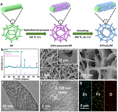
The synthesis process for ZnFe2O4/NF is presented in Fig. 1a (see the ESI† for details). Fig. 1 shows the X-ray diffraction (XRD) pattern for ZnFe2O4/NF. Three distinct diffraction peaks at 44.5°, 51.9°, and 76.4° correspond to the NF substrate (JCPDS no. 71-3740), and the four peaks at 18.2°, 36.9°, 42.9°, and 62.50° can be attributed to the ZnFe2O4 phase (JCPDS no. 03-7430). The scanning electron microscopy (SEM) images (Fig. 1c and d and S1†) illustrate the full coverage of ZnFe2O4 nanosheet arrays on NF. We also prepared Fe3O4/NF (Fig. S2†) using the same procedure but without the inclusion of a Zn source. The nanosheet structure of ZnFe2O4 is unveiled as shown by the transmission electron microscopy (TEM) image (Fig. 1e). The high-resolution TEM (HRTEM) image (Fig. 1f) reveals a d-spacing of 0.150 nm indexed to the (440) plane of ZnFe2O4. In Fig. 1g, the energy dispersive X-ray (EDX) elemental mapping images confirm a uniform distribution of the Zn, Fe, and O elements throughout the entirety of ZnFe2O4.
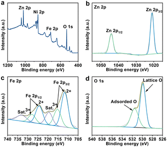
To gain insight into the surface composition and bonding state of ZnFe2O4, X-ray photoelectron spectroscopy (XPS) analysis was performed. The survey XPS spectrum presented in Fig. 2a reveals the presence of the Zn, Fe, O, and Ni elements in ZnFe2O4, with the Ni component originating from NF. As described in Fig. 2b, the double peaks at 1020.9 and 1044.2 eV in the Zn 2p core-level spectrum are deconvoluted into 2p3/2 and 2p1/2 of Zn2+.39,40 In the Fe 2p region of Fig. 2c, the existence of Fe3+ and Fe2+ in ZnFe2O4 is evidenced by the characteristic peaks at 715.3, 727.9, 711.7, and 724.4 eV, respectively.40,41 Additional peaks at 719.5 and 733.2 eV are classified as shake-up satellites (Sat.). The spectrum for O 1s (Fig. 2d) is divided into two main peaks at 529.9 and 531.6 eV, which match lattice O in the catalyst and adsorbed O on its surface, respectively.39,42
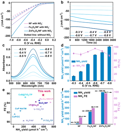
The electrocatalytic performance of ZnFe2O4/NF for the eNO2−RR was evaluated using an H-type cell, incorporating a three-electrode system, in a 0.1 M NaOH solution containing 0.1 M NO2− under argon saturation. Taking into account the high volatility of NH3, the cathodic compartment was sealed during testing. All electrochemical measurements were conducted at a stirring rate of 600 rpm. The primary product, NH3, and the associated by-products, N2H4, H2, and N2, resulting from the eNO2−RR, were quantitatively determined using UV-vis spectrophotometry and gas chromatography. Calibration curves for NH3 and N2H4 are given in Fig. S3 and S4.† We collected the linear sweep voltammetry (LSV) curves for ZnFe2O4/NF with a scan rate of 5 mV s−1. The LSV curves (Fig. 3a) suggest a substantial improvement in the current density (j) of ZnFe2O4/NF in the presence of NO2−, reaching 201.40 mA cm−2 at −1.0 V, much higher than the value of 102.95 mA cm−2 in pure NaOH solution. This increase underscores the superior performance of ZnFe2O4/NF for NO2− reduction. Additionally, under the same test conditions, NF and Fe3O4/NF exhibits significantly lower current densities of 108.19 and 136.28 mA cm−2, respectively, at −1.0 V. We further conducted chronoamperometry (CA) tests at various potentials, ranging from −0.3 to −0.8 V. The NH3 concentrations were determined using UV-vis spectrophotometry (refer to Fig. 3b and c and S5†). As depicted in Fig. 3d, the NH3 yield of ZnFe2O4/NF steadily increases with the rise in cathode potential, reaching a maximum value of 771.93 μmol h−1 cm−2 at −0.8 V. Meanwhile, the NH3 FE achieves its peak at 95.7% at −0.6 V. Notably, in order to further investigate NH3 yield and FE of ZnFe2O4/NF, chronoamperometry (CA) tests were enforced at various potentials (from −0.3 to −0.8 V) and NH3 concentrations were determined by UV-vis spectrophotometry (Fig. 3b and c and S5†). Remarkably, the catalytic activity of ZnFe2O4/NF for the eNO2−RR surpasses that of the majority of electrocatalysts reported in the recent literature (Fig. 3e and Table S1†). Similarly, control samples underwent electrolysis for 1 h at −0.6 V (Fig. S6a†), with the corresponding NH3 product absorbances provided in Fig. S6b.† Ultimately, as depicted in Fig. 3f, it becomes evident that the catalytic activity of ZnFe2O4/NF significantly outperforms that of NF (14.95 μmol h−1 cm−2, 20.42% FE) and Fe3O4/NF (229.54 μmol h−1 cm−2, 50.05% FE). We determined the electrochemical double-layer capacitance (Cdl) to assess the electrochemically active surface area (ECSA) of the prepared samples, as illustrated in Fig. S7a and b.† Cyclic voltammograms (CV) were collected within the voltage range of 0.8 to 0.9 V. Fig. S7c† reveals that the Cdl values for Fe3O4/NF and ZnFe2O4/NF are 1.10 and 1.61 mF cm−2, respectively. This indicates that ZnFe2O4/NF exhibits higher surface roughness, thus exposing a greater number of catalytically active sites. Additionally, the electrochemical impedance spectra (Fig. S7d†) indicate that the charge transfer resistance of ZnFe2O4/NF is lower compared to that of Fe3O4/NF, which facilitates faster charge transfer. These results collectively demonstrate that the introduction of the Zn elements significantly enhances the catalytic performances.
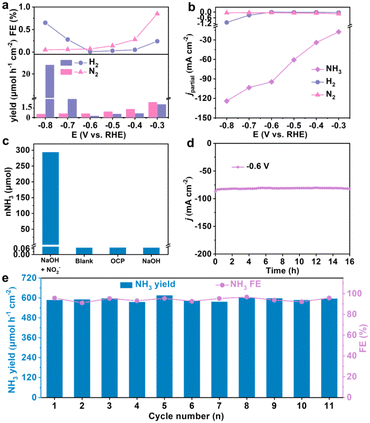
Assessing the overall effectiveness of the catalyst also entails the detection of potential by-products, namely N2H4, H2, and N2. The data presented in Fig. S8† indicates the absence of N2H4 formation in the electrolyte within the test voltage range spanning from −0.3 to −0.8 V. Additionally, the NH3 yields and FEs of H2 and N2 in the electrolyte after electrolysis at various potentials are significantly lower than those of NH3 (Fig. 4a). This observation elucidates that NH3 is the primary product in the NO2− reduction process and that the HER is predominantly suppressed. Furthermore, in Fig. 4b, it is evident that the partial current density (jpartial) of NH3 (94.65 mA cm−2) significantly surpasses that of H2 (0.01 mA cm−2) and N2 (0.07 mA cm−2) at −0.6 V, confirming the exceptional selectivity of ZnFe2O4/NF for NH3 production from NO2−.
To ascertain that the generated NH3 indeed arises from the eNO2−RR on ZnFe2O4/NF, a series of control experiments were carried out at −0.6 V. The corresponding UV-vis absorption spectra are presented in Fig. S9.† The results obtained after testing under various conditions are illustrated in Fig. 4c, where substantial amounts of NH3 were detected in the electrolyte. Simultaneously, the NH3 yields in the cathode chamber were only 0.070, 0.072, and 0.071 μmol after 1 h electrolysis in blank electrolyte, an open circuit potential (OCP), and pure 0.1 M NaOH. This unequivocally rules out nitrogen contamination from the electrolyzer and reagents, thus indicating that the generated NH3 originates exclusively from NO2− in the electrolyte. Stability is a crucial parameter for assessing catalyst activity. To evaluate the stability of ZnFe2O4/NF, it underwent an electrolysis test for 16 h in a solution of 0.1 M NaOH and 0.1 M NO2− (Fig. 4d). Over the extended test duration, ZnFe2O4/NF exhibited only a minor decrease in j, indicating its exceptional electrochemical stability. Simultaneously, we assessed the NH3 yields and FEs both before and after the 16 h electrolysis to further confirm the stability of ZnFe2O4/NF. Even after 16 h electrolysis, the NH3 yield attains 577.13 μmol h−1 cm−2, with a slight decrease in FE to approximately 93.7% (Fig. S10†). The LSV curves remain identical before and after long-term electrolysis (Fig. S11†), demonstrating the high stability of the electrocatalyst. In addition, we conducted continuous cycling tests at −0.6 V, replacing the electrolyte after each cycle. Remarkably, we observed nearly overlapping CA curves and UV-vis absorption spectra for each cycle (Fig. S12†). Furthermore, negligible fluctuations in NH3 yields and FEs were observed over the course of 11 cycles (Fig. 4e), providing strong evidence of the exceptional long-term durability of ZnFe2O4/NF. Of note, the XRD pattern and SEM images (Fig. S13†) and XPS spectra (Fig. S14†) indicate minimal changes in the crystal phase, microstructure, and valence state of ZnFe2O4 after 16 h electrolysis. All above observations evidence the remarkable electrochemical and structural stability of our catalyst.
In conclusion, the ZnFe2O4 nanoarray is proven as a highly active electrocatalyst for the eNO2−RR in alkaline environments. Incorporating Zn into the structure significantly enhances both the ECSA and electrical conductivity. It achieves an outstanding FE of 95.7% with a large NH3 yield of 588.58 μmol h−1 cm−2 at −0.6 V. This work not only provides us with an efficient electrocatalyst for the production of value-added NH3 but would be an inspiration for future design and exploration of Fe-based bimetallic oxides for applications.
Conflicts of interest
There are no conflicts to declare.Acknowledgements
The authors extend their appreciation to the Deanship of Scientific Research at King Khalid University for funding support through large group Research Project under (grant no. RGP2/257/44).References
- J. Liang, Q. Liu, A. A. Alshehri and X. Sun, Nano Res. Energy, 2022, 1, e9120010 CrossRef.
- H. Qiu, Q. Chen, J. Zhang, X. An, Q. Liu, L. Xie, W. Yao, X. Sun and Q. Kong, Inorg. Chem. Front., 2023, 10, 3909–3915 RSC.
- A. Klerke, C. H. Christensen, J. K. Nørskov and T. Vegge, J. Mater. Chem., 2008, 18, 2304–2310 RSC.
- J. Liang, Z. Li, L. Zhang, X. He, Y. Luo, D. Zheng, Y. Wang, T. Li, H. Yan, B. Ying, S. Sun, Q. Liu, M. S. Hamdy, B. Tang and X. Sun, Chem, 2023, 9, 1768–1827 CAS.
- H. Zhu, S. Dong, X. Du, H. Du, J. Xia, Q. Liu, Y. Luo, H. Guo and T. Li, Catal. Sci. Technol, 2022, 12, 4998–5002 RSC.
- X. He, L. Hu, L. Xie, Z. Li, J. Chen, X. Li, J. Li, L. Zhang, X. Fang, D. Zheng, S. Sun, J. Zhang, A. A. Alshehri, Y. Luo, Q. Liu, Y. Wang and X. Sun, J. Colloid Interface Sci., 2023, 634, 86–92 CrossRef CAS PubMed.
- Q. Hua, H. Zhu, S. Xue, F. Zhao, Z. Liang, X. Ren, L. Gao, T. Ma and A. Liu, Catal. Sci. Technol, 2023, 13, 4558–4567 RSC.
- L. Ouyang, J. Liang, Y. Luo, D. Zheng, Q. Liu, S. Sun, M. S. Hamdy, X. Sun and B. Ying, Chin. J. Catal., 2023, 50, 6–44 CrossRef CAS.
- Y. Liu, E. Huixiang Ang, X. Zhong, H. Lu, J. Yang, F. Gao, C. Yu, J. Zhu, C. Zhu, Y. Zhou, F. Yang, E. Yuan and A. Yuan, J. Colloid Interface Sci., 2023, 652, 418–428 CrossRef CAS PubMed.
- L. Tao, K. Pang, W. Qin, L. Huang, L. Duan, G. Zhu, Q. Li and C. Yu, Catal. Sci. Technol, 2023, 13, 4517–4524 RSC.
- D. Chanda, R. Xing, T. Xu, Q. Liu, Y. Luo, S. Liu, R. A. Tufa, T. H. Dolla, T. Montini and X. Sun, Chem. Commun., 2021, 57, 7335–7349 RSC.
- X. He, Z. Li, J. Yao, K. Dong, X. Li, L. Hu, S. Sun, Z. Cai, D. Zheng, Y. Luo, B. Ying, M. S. Hamdy, L. Xie, Q. Liu and X. Sun, iScience, 2023, 26, 107100 CrossRef CAS PubMed.
- Y. Feng, J.-T. Ren, H.-Y. Wang, L. Wang and Z.-Y. Yuan, Inorg. Chem. Front., 2023, 10, 4510–4518 RSC.
- X. He, X. Li, X. Fan, J. Li, D. Zhao, L. Zhang, S. Sun, Y. Luo, D. Zheng, L. Xie, A. M. Asiri, Q. Liu and X. Sun, ACS Appl. Nano Mater., 2022, 5, 14246–14250 CrossRef CAS.
- X. Zhang, Y. Wang, Y. Wang, Y. Guo, X. Xie, Y. Yu and B. Zhang, Chem. Commun., 2022, 58, 2777–2787 RSC.
- Z. Ren, Q. Chen, J. Zhang, X. An, Q. Liu, L. Xie, W. Yao, X. Sun and Q. Kong, Mater. Today Phys., 2023, 36, 101162 CrossRef CAS.
- J. R. Stroka, B. Kandemir, E. M. Matson and K. L. Bren, ACS Catal., 2020, 10, 13968–13972 CrossRef CAS.
- T. Zhao, X. Li, J. Hu, J. Zhou, X. Jia and G. Hu, J. Environ. Chem. Eng., 2023, 11, 110122 CrossRef CAS.
- Y. Ren, Q. Zhou, J. Li, X. He, X. Fan, Y. Fu, X. Fang, Z. Cai, S. Sun, M. S. Hamdy, J. Zhang, F. Gong, Y. Liu and X. Sun, J. Colloid Interface Sci., 2023, 645, 806–812 CrossRef CAS PubMed.
- J. P. Troutman, H. Li, A. M. Haddix, B. A. Kienzle, G. Henkelman, S. M. Humphrey and C. J. Werth, ACS Catal., 2020, 10, 7979–7989 CrossRef CAS.
- O. Einsle, A. Messerschmidt, P. Stach, G. P. Bourenkov, H. D. Bartunik, R. Huber and P. M. H. Kroneck, Nature, 1999, 400, 476–480 CrossRef CAS PubMed.
- J. Wang, T. Feng, J. Chen, V. Ramalingam, Z. Li, D. M. Kabtamu, J.-H. He and X. Fang, Nano Energy, 2021, 86, 106088 CrossRef CAS.
- O. Winther-Jensen and B. Winther-Jensen, Electrochem. Commun., 2014, 43, 98–101 CrossRef CAS.
- A. Zhang, Y. Liang, X. He, X. Fan, C. Yang, L. Ouyang, D. Zheng, S. Sun, Z. Cai, Y. Luo, Q. Liu, S. Alfaifi, L. Cai, H. Wang and X. Sun, Inorg. Chem., 2023, 62, 12644–12649 CrossRef CAS PubMed.
- J. Yuan, H. Yin, X. Jin, D. Zhao, Y. Liu, A. Du, X. Liu and A. P. O'Mullane, Appl. Catal., B, 2023, 325, 122353 CrossRef CAS.
- D. Zhu, B. Zhang, J. Chen, F. Xie, Y. Zou and P. Chen, Chem. Commun., 2023, 59, 9626–9629 RSC.
- Y. Feng, L. Chen and Z. Yuan, Inorg. Chem. Front., 2023, 10, 5225–5243 RSC.
- A. A. Pawar, H. A. Bandal and H. Kim, J. Alloys Compd., 2021, 863, 158742 CrossRef CAS.
- A. Kafle, D. Gupta, A. Bordoloi and T. C. Nagaiah, Nanoscale, 2022, 14, 16590–16601 RSC.
- X. Fan, L. Xie, J. Liang, Y. Ren, L. Zhang, L. Yue, T. Li, Y. Luo, N. Li, B. Tang, Y. Liu, S. Gao, A. A. Alshehri, Q. Liu, Q. Kong and X. Sun, Nano Res., 2021, 15, 3050–3055 CrossRef.
- S. Li, L. Huang, Q. Zhang, H. Lin, R. Wang, C. Feng, Y. Xu, Y. Jiao, L. You and J. Chen, Int. J. Hydrogen Energy, 2023 DOI:10.1016/j.ijhydene.2023.07.015.
- M. Marcos-Hernández, G. Antonio Cerrón-Calle, Y. Ge, S. Garcia-Segura, C. M. Sánchez-Sánchez, A. S. Fajardo and D. Villagrán, Sep. Purif. Technol., 2022, 282, 119771 CrossRef.
- S. R. Powell, J. Nutr., 2000, 130, 1447S–1454S CrossRef CAS PubMed.
- T. M. Bray and W. J. Bettger, Free Radical Biol. Med., 1990, 8, 281–291 CrossRef CAS PubMed.
- N. C. Lim, H. C. Freake and C. Brückner, Chem. – Eur. J., 2005, 11, 38–49 CrossRef PubMed.
- Z. Li, J. Liang, Q. Liu, L. Xie, L. Zhang, Y. Ren, L. Yue, N. Li, B. Tang, A. A. Alshehri, M. S. Hamdy, Y. Luo, Q. Kong and X. Sun, Mater. Today Phys., 2022, 23, 100619 CrossRef CAS.
- S. Dong, A. Niu, K. Wang, P. Hu, H. Guo, S. Sun, Y. Luo, Q. Liu, X. Sun and T. Li, Appl. Catal., B, 2023, 333, 122772 CrossRef CAS.
- Q. Zhao, Z. Yan, C. Chen and J. Chen, Chem. Rev., 2017, 117, 10121–10211 CrossRef CAS PubMed.
- Y. Guo, N. Zhang, X. Wang, Q. Qian, S. Zhang, Z. Li and Z. Zou, J. Mater. Chem. A, 2017, 5, 7571–7577 RSC.
- J. G. Monsalve, C. Ostos, E. Ramos, J. G. Ramírez and O. Arnache, Curr. Appl. Phys., 2021, 22, 77–83 CrossRef.
- X. He, J. Li, R. Li, D. Zhao, L. Zhang, X. Ji, X. Fan, J. Chen, Y. Wang, Y. Luo, D. Zheng, L. Xi, S. Sun, Z. Cai, Q. Liu, K. Ma and X. Sun, Inorg. Chem., 2023, 62, 25–29 CrossRef CAS PubMed.
- Z. Hu, Z. Jin, S. Gong, X. Wei, J. Zhao, M. Hu, J. Zhao, Z. Chen, Z. Pan and X. Li, Catal. Sci. Technol, 2022, 12, 3137–3147 RSC.
Footnotes |
| † Electronic supplementary information (ESI) available. See DOI: https://doi.org/10.1039/d3cy01176c |
| ‡ Both authors contributed equally to this work. |
| This journal is © The Royal Society of Chemistry 2024 |


