
Neutral pH Fenton and photo-Fenton activity of Mo-doped iron-pyrite particles†
Maheswari
Yadav
a,
Uttam
Kumar
a,
Arup
Kumar De
ab and
Indrajit
Sinha
 *a
*a
aDepartment of Chemistry, Indian Institute of Technology (Banaras Hindu University), Varanasi 221005, India
bKnowledge Resources & Information Technology Division, CSIR-National Metallurgical Laboratory, Jamshedpur-831007, India. E-mail: isinha.apc@iitbhu.ac.in
First published on 5th August 2024
Abstract
Low H2O2 utilization efficiency for hydroxyl radical generation, acidic pH, and recyclability are critical limitations of heterogeneous Fenton and photo-Fenton catalysts. The present research shows that the optimum Mo doping of FeS2 particles can largely alleviate these catalysis constraints. A solvothermal protocol was followed to prepare polyvinyl pyrrolidone (PVP) stabilized FeS2 and Mo-doped FeS2 particles. XRD observations showed that Mo doping increases the lattice parameters of FeS2. The band gap of the Mo-doped FeS2 particles decreased to 1.58 eV from the 2.24 eV value exhibited by pure FeS2 particles. Structural and electronic structure DFT calculations support these results. The Fenton and photo-Fenton p-nitrophenol (PNP) degradation at neutral pH on PVP-stabilized Mo-doped FeS2 and FeS2 particles were examined. The photo-Fenton results were substantially better than under Fenton conditions. The best PNP degradation photo-Fenton turnover frequency (TOF) recorded was 254.50 μmol g−1 min−1 on the PVP stabilized 4% Mo-doped FeS2 sample. The Mo-doped FeS2 catalysts were stable under photo-Fenton recycling, and the H2O2 (1.66 mM) required for these reactions was significantly lower than most reports (30–6000 mM). Given the economic importance of the latter in Fenton/photo-Fenton reactions, H2O2 normalized turnover frequency (13.85 and 153.31 mg−1 min−1 L for Fenton and photo-Fenton) values were used to evaluate catalytic activities.
1. Introduction
The Fenton reaction is a well-known method for degrading organic pollutants in wastewater from various sources. The conventional homogeneous Fenton reaction involves the reductive cleavage of H2O2 to generate hydroxyl radicals using a ferrous salt as a catalyst (Fe2+ + H2O2 → Fe3+ + OH− + ˙OH). The hydroxyl radical released in this process is a powerful non-selective oxidant for organic molecules. The classical Fenton reaction has several limitations. While the forward reaction (Fe2+ to Fe3+ oxidation) is fast, the reverse process for the regeneration of the Fe2+ ions is much slower, resulting in the accumulation of Fe3+ salt and poor recyclability. Moreover, low pH conditions are necessary because neutral or higher pH can cause Fe(OH)3 precipitation, which takes out Fe species from the catalyst. This process drastically reduces the recyclability of Fe2+ species to Fe3+ and back. Lower pH prevents this phenomenon and ensures better catalyst utilization and consequently hydroxyl radical production. Another critical issue is the H2O2 utilization efficiency, which determines the running cost of commercial Fenton and photo-Fenton processes. Most advanced oxidation processes report H2O2 concentration in the 30–6000 mmol L−1 range.1 Only a few homogeneous or heterogeneous Fenton/photo-Fenton publications give the H2O2 utilization data.Most heterogeneous Fenton catalysts (particles or nanoparticles) also exhibit improved Fenton activity under acidic conditions. The conversion of Fe3+ to Fe2+ (Fe3+ + ˙OOH → Fe2+ + H+ + O2) for the catalyst regeneration is still the main rate-limiting step. Only a few heterogeneous catalysts have been investigated for their neutral pH Fenton activities. Thus, developing effective nanocatalysts that can operate a Fenton-like reaction under neutral pH conditions is a topical area of research. Extensively chelated Fenton nanocatalysts (succinates, citrates, tartrates, ethylene diamine tetra-acetic acid, etc.) remain soluble even under neutral pH conditions2–5 and prevent the precipitation of Fe(OH)3. Nonetheless, these chelating agents also scavenge hydroxyl radicals which slows down the degradation kinetics of the target organic pollutants.
Recently, Zhou et al. demonstrated that glutathione-functionalized magnetite nanoparticles catalyzed Fenton-like degradation of dichlorophenol under neutral pH conditions.6 Apparently, the thiol group in the glutathione molecule is responsible for its Fenton catalytic activity.7 In this context, there are a few reports in recent literature on the use of iron pyrite nanoparticles as heterogeneous Fenton catalysts at neutral pH. For instance, Bae et al.8 reported diclofenac degradation under near-neutral Fenton conditions on FeS2 particles. There is also a report on the Fenton catalytic activity for p-nitrophenol (PNP) degradation on natural and synthesized iron pyrite particles.9 Nevertheless, these publications have either not investigated the recyclability of FeS2 particles as Fenton catalysts for PNP degradation or the ref. 8 recyclability of bare FeS2 particles after the first cycle (of PNP degradation) is quite poor. The poor recyclability is mainly because the reconversion of Fe3+ to Fe2+ requires catalyst degradation by sulfate formation.
Though FeS2 is a small bandgap semiconductor, there are very few investigations on the photo-Fenton properties of these materials.8 The recyclability reported by Zeng et al. for photo-Fenton PNP degradation on bare FeS2 is worse than the Fenton case. Molybdenum, like Fe, also exists in multiple oxidation states, which can help regenerate Fe2+ from Fe3+ sites. Furthermore, such doping can also slow down photoexcited charge recombination kinetics,10 enhancing the photo-Fenton activity of the catalyst. It has been reported that MoS2 is a good co-catalyst for the homogeneous Fenton reaction reduction of H2O2.11 Given the above literature survey, the research in the present article investigates the Fenton and photo-Fenton PNP degradation activities of molybdenum-doped and undoped PVP (polyvinyl pyrrolidone) stabilized FeS2 particles. PNP is a non-degradable toxic intermediate synthesizing various chemicals in the pharmaceutical and dyes industries. It can cause several health issues like drowsiness, headaches, nausea, etc. PNP oxidative degradation is critical to water purification.
There is no investigation on the effect of Mo-doping of FeS2 on its Fenton and photo-Fenton PNP degradation activity. Hence, the present research investigates Fenton and photo-Fenton activities of Mo-doped FeS2 particles for PNP degradation under neutral pH conditions. Mo exists in +4 and +6 oxidation states. It is possible that electron transfer from the dopant (in its +4 state) to Fe3+ can reduce it back to Fe2+ state. The latter should enhance the Fenton/photo-Fenton activity of the catalyst. Consequently, the investigations in the present research emphasize the catalyst utilization, H2O2 requirement, and recyclability of the catalyst under Fenton and photo-Fenton conditions. A solvothermal protocol was used to prepare polyvinyl pyrrolidone (PVP) stabilized Mo-doped FeS2 particles with 1, 4, and 8-mole percent Mo dopants. PVP functionalization of the particle surface reduced the interaction of the sulfur on the surface with the aqueous medium. The prepared materials were thoroughly characterized by X-ray diffraction (XRD), transmission electron microscopy (TEM), X-ray photoelectron spectroscopy, etc. Photoluminescence and solid-state UV visible spectroscopy were used to analyze the excited species recombination and the optical band gap of the prepared materials. Plane-wave density functional theory (DFT) calculations were carried out along with exhaustive experimental investigations. The DFT results complement experimental observations on the dopant (Mo) position in the FeS2 lattice. Furthermore, the change in the electronic structure of FeS2 due to Mo doping was also calculated. The DFT calculation inputs help ascertain possible Fenton and photo-Fenton mechanisms.
2. Experimental section
2.1 Experimental reagents
FeCl2·4H2O and elemental sulfur were purchased from SRL Chemical. (NH4)6Mo7O24·4H2O, the molybdenum precursor, was purchased from Sigma Aldrich. Polyvinyl pyrrolidone (PVP), NaOH, and ethylene glycol (EG) were supplied by Merck. Isopropyl alcohol (IPA) was purchased from Himedia. PNP was procured from Spectrochem Mumbai. All chemicals were of analytical grade and used without further purification. 30% W/V H2O2 was purchased from Qualigens.2.2 Iron pyrite synthesis
A solvothermal method was used to synthesize PVP-stabilized iron pyrite particles.12,13 0.32 g of FeCl2·4H2O was dissolved in 50 mL ethylene glycol with vigorous stirring. Next, 1.16 g of PVP was added and stirred to obtain a yellow-colored solution. This solution was poured into 10 mL of 1 M NaOH solution. The color of the reaction mixture changed from yellow to dark green. After half an hour of vigorous stirring, 0.33 g of elemental sulfur was added to the reaction mixture. Stirring was continued until the color of the reaction mixture changed from dark green to dark red color. Finally, the reaction mixture was transferred to a 100 mL autoclave and kept in an oven at 180 °C for 24 hours. The reaction mixture was allowed to cool at room temperature. The resultant black suspension was centrifuged, and the precipitate was washed multiple times with double distilled water. Ethanol was used for the final washing. The washed product was dried at 50 °C overnight. The powder sample was heated at 100 °C for one hour in a vacuum oven to remove excess elemental sulfur in the product. Hereafter, the abbreviation Py denotes this PVP-stabilized iron pyrite sample.2.3 Molybdenum doped iron pyrite synthesis
The weights of (NH4)6Mo7O24·4H2O and FeCl2·4H2O were taken such that the percentage of Mo in the doped FeS2 was 1, 4, and 8 moles% only. Hereafter, the 1, 4, and 8 moles percentages of Mo-doped FeS2 samples were denoted as Py1, Py4, and Py8 respectively. Py1, Py4, and Py8 were prepared using 1, 4, and 8 moles percentage (NH4)6Mo7O24·4H2O of FeCl2·4H2O. Doped FeS2 samples were prepared by dissolving Mo and Fe precursors (in the desired ratio) in 50 mL ethylene glycol with continuous stirring in the first step of the earlier discussed Py preparation protocol. The rest of the steps were the same as in the Py preparation protocol.2.4 Fenton reaction catalysis protocol
2 mg of catalyst powder was added into the 2 mL double distilled water. Further, this mixture was sonicated for 1 hour using a bath sonicator. In each experiment, 50 μL of 2 mg/2 mL catalyst suspension was added to 3 mL of 10 ppm aqueous solution of the target organic pollutant (PNP) in a 4 mL cuvette. The prepared mixture was stored in the dark for 90 minutes with continuous stirring to establish adsorption–desorption equilibrium. The Fenton reaction was started by adding appropriate amounts of H2O2 to this reaction mixture. Fenton activity of the catalyst was evaluated for the degradation of PNP in an aqueous solution. The change in the UV-visible spectrum of the target organic molecule with time at room temperature was used to monitor the degradation kinetics. The hydroxyl radical is expected to be the active species in a Fenton oxidation reaction. To confirm this a Fenton catalysis experiment was carried out in the presence of isopropyl alcohol (IPA), a hydroxyl radical scavenger.2.5 Photo-Fenton experiment details
The photo-Fenton activities of the synthesized catalysts were examined for PNP degradation under cool white LED visible light irradiation. In each experiment, 30 μL of 2 mg/2 mL catalyst suspension was added to 10 ppm PNP (3 mL volume) aqueous solution. The prepared mixture was stored in the dark for 60 min with continuous stirring to establish adsorption–desorption equilibrium. Now, an appropriate amount of H2O2 was added to this mixture. After this, the mixture was placed under a 14 W Philips cool white LED light chamber to check its photo-Fenton activity. The absorption spectra of the mixture were recorded every 2 min time interval. The photo-Fenton scavenger experiment protocol was similar to that outlined in the previous sub-section but was done under a cool white LED light source.2.6 Recyclability experiment details
The reusability of the catalysts prepared in this study was investigated by the following protocol. At the end of a Fenton or photo-Fenton experiment, the reaction mixture was centrifuged to recover the catalyst. The recovered catalyst after each cycle was washed several times with double distilled water, dried, and weighed. The PNP degradation obtained after the first cycle was assumed to be 100%. The recovered catalyst was then used for the next cycle. The rest of the procedure for catalyst reuse was the same as the first cycle. PNP degradation obtained in subsequent cycles was calculated relative to that obtained in the first cycle. The photo-Fenton recyclability protocol was similar to the Fenton reaction except for the photocatalysis under a cool white LED light source.2.7 Characterization
X-ray diffractions of Py, Py1, Py4, and Py8 powder samples were carried out on a Rigaku Mini-X 600 (Japan) instrument using Cu Kα radiation (1.54046 Å) from 2θ value 5° to 90° at a 5° min−1 scan rate and 0.01 step size. The Shimadzu Pharmaspec UV-1700 model was used for the solid-state UV-visible diffuse reflectance spectroscopy (UV-DRS) in the 200–800 nm spectral range. UV-visible spectra of the targeted organic pollutants (in an aqueous medium) were monitored regularly on an Agilent Cary 60 instrument. X-ray photoelectron spectroscopy (XPS) determined the elements making the catalyst surface and their oxidation states. XPS also gave the valence band position of the prepared FeS2 materials. Scanning electron microscopy (SEM) images were taken on Nova Nano SEM 450. The Fluoromax Plus model (Horiba) was used for the photoluminescence studies.2.8 Computational details
All plane-wave DFT calculations were performed using the MedaA Vienna ab initio simulation package (VASP). The generalized gradient approximation – Perdew–Burke–Ernzerhof (GGA–PBE) functional was used to optimize the structure and calculate the defect formation energy.14 Initially, a 2 × 2 × 2 supercell was built from the FeS2 unit cell (Card No: COD 9013069). The supercell was optimized using a 4 × 4 × 4 k-point mesh size and 400 eV plane wave basis set energy cut-off.15 The optimized FeS2 model is labeled as P0. Mo-doping of FeS2 can happen either by substituting a Fe site or by the dopant atom occupying an interstitial (hole) position. Thus, two models were constructed. One has a Fe atom substituted by a Mo atom, and in the second, Mo was placed in an interstitial position. Hereafter, the substituted and interstitial Mo-doped models are denoted by P1 and P2 models, respectively (Fig. 1).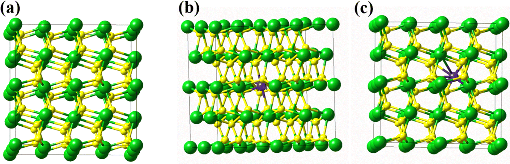 | ||
| Fig. 1 (a) The iron pyrite 2 × 2 × 2 supercell, (b) Mo at the substituted position (P1 model), and (c) Mo at the interstitial position (P2 model). In the supercell, the green, yellow, and purple balls denote Fe atoms, S dimer, and Mo atoms respectively. | ||
3. Results and discussion
3.1 Characterization
 | ||
| Fig. 2 (a) Powder XRD patterns of Py, Py1, Py4, and Py8 samples. (b) FeS2(200) peak position with Mo doping. (c) change in lattice parameter with Mo-doping of FeS2. (d) SEM image of the Py4 sample. (e) SEM image of region subjected to elemental mapping. (f) displays the elemental map of Mo. (g) Fe. (h) S atoms, and (i) particle size distribution of this sample. | ||
Fig. 2(b) compares the most intense (200) peaks for Py, Py1, Py4, and Py8 samples. An increase in Mo doping till 4% doping (Py4) shifted the (200) peak position slightly towards the smaller 2θ side, indicating lattice expansion.16 However, the peak shifting is not the same in all doped samples. Fig. 2(c) shows the lattice parameter versus the dopant mole percent scatter plot. The lattice parameter increases with doping till 4% Mo. The lattice parameter of the Py8 sample deviates only slightly from the Py sample. Note that 0.79 and 0.75 nm are the effective ionic radii of Mo4+ and Fe2+, respectively.17,18 Since the difference between these two ionic radii is very small (5.06%), it is possible that Mo4+ substitutes Fe2+ in the FeS2 lattice. We come back to this issue while discussing the DFT calculation results. Furthermore, peak broadening increased until 4% Mo doping of the FeS2 system. Py, Py1, Py4, and Py8 crystallite sizes were 34.83 nm, 30.57 nm, 27.40 nm, and 29.80 nm, respectively. Thus, sample Py4 has the least crystallite size among all samples. Table M1 (ESI†) shows the calculation, reading, and instrument precision error percentage in lattice parameter calculation. All these errors are negligible.
Fig. 2(d) displays a typical SEM micrograph of the Py4 sample. The particles are roughly spherical. Fig. 2(e) gives the SEM image of the region over which elemental mapping has been carried out. The elemental mapping of the Py4 sample shows that Fe, S, and Mo are uniformly distributed in the particles making up the region. Fig. 2(i) gives the particle size distribution of the Py4 sample, plotted using statistics over 270 particles. This sample's average particle size is approximately 325 nm.
 | (1) |
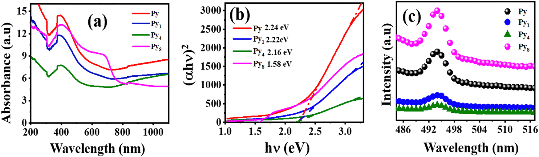 | ||
| Fig. 3 (a) UV-diffusion reflectance spectra of Py, Py1, Py4, and Py8 samples. (b) direct band gap plot of Py, Py1, Py4, and Py8 samples. (c) Photoluminescence spectra of Py, Py1, Py4, and Py8 catalyst. | ||
The x-axis intercept of the fit to the linear portion of the Tauc plot gives the band gap of the sample. The direct band gap of the Py sample is 2.24 eV, in agreement with the previously reported PVP-stabilized iron pyrite nanoparticle band gap in literature.21,22 The band gap decreased after Mo-doping to 2.22, 2.16, and 1.58 eV for Py1, Py4, and Py8 samples respectively.
 | ||
| Fig. 4 (a) S 2p and (b) Fe 2p spectra of Py and Py4 samples. (c) HR-XPS of the Mo 3d spectrum of Py4 sample. (d) Valence band XPS spectra of Py and Py4 samples. | ||
The core level S 2p spectrum also shows peaks at 161.57 and 164.5 eV, implying the presence of S− ions. Thus, S2− and S− ions exist in both samples. The deconvoluted S 2p spectra (of Py and Py4) also display small sulfate peaks at 167.68 and 168.85 eV due to slight surface oxidation. Fig. 4(b) shows the high-resolution Fe 2p XPS spectra of Py and Py4 samples. Two major peaks at 709.96 eV and 723.30 eV denote 2p3/2 and 2p1/2 of Fe2+ in the Py respectively.25 One peak of Fe3+ was obtained at 713.74 eV, which represents the partial oxidation of Py due to thermal treatment during sample preparation.
Fig. 4(c) shows the Mo 3d spectra of the Py4 sample. There are two 3d3/2 and 3d5/2 peaks at 231.8 and 227.8 eV, confirming that Mo ions are present in the +4-oxidation state.26Fig. 4(c) also shows one peak of S 2s at 226.04 eV.16 The Fe 2p peaks in the Py4 sample show a 0.6 eV shift towards higher binding energy. Thus, electron density on Fe2+ decreased after Mo doping because of its higher electronegativity. Fig. 4(d) shows the valence band spectra of Py and Py4 samples. In this spectrum, the valence band positions of Py and Py4 samples are 0.276 eV and −0.254 eV respectively. Eqn (2) was used to calculate the CB position of samples.
| ECB = EVB − Eg | (2) |
3.2 DFT studies
DFT calculations were used to investigate the position of the dopant Mo atom in the FeS2 lattice. The formation energies of the interstitial and substituted Mo-doped FeS2 supercell models were found to elucidate this issue. The formation energies of the substituted and interstitially doped systems are calculated using eqn (3) and (4).| Ef = Edefect(sub) − {Eperfect(FeS2) − μFe + μMo} | (3) |
| Ef = Edefect(Interstitial) − {Eperfect(FeS2) + μMo} | (4) |
In these equations, Ef is the formation energy, Eperfect(FeS2) is the energy of the perfect FeS2 supercell, Edefect(sub) is the energy of the Mo-substituted FeS2 model, Edefect is the energy of the model where Mo occupies an interstitial position, μFe, and μMo are the chemical potentials of iron and molybdenum element.17 The formation energies are 1.855 eV and 4.904 eV for the P1 (substituted) and P2 (interstitial) models. Thus, Mo-substituting a Fe in FeS2 is more favorable than the interstitially doped model. Table 1 compares the DFT-calculated supercell parameters of the undoped and the Mo-substituted models. All dimensions of the cubic cell expand uniformly due to Mo-substituting a Fe atom in the FeS2 model. These DFT results are exactly analogous to experimental XRD results that showed FeS2 lattice expansion with Mo-doping till the 4% Mo level. The agreement between the DFT calculation and experimental results enables us to infer that the Mo-substitution of a Fe atom makes the FeS2 lattice expand.
| Dimension | Pure FeS2 | After Mo doping |
|---|---|---|
| X | 5.395343 Å | 5.412729 Å |
| Y | 5.395343 Å | 5.412729 Å |
| Z | 5.395343 Å | 5.412729 Å |
| A | 90° | 90.007825° |
| β | 90° | 90.007825° |
| γ | 90° | 90.007825° |
We also analyzed the electronic structures of the investigated models to better understand the photocatalytic properties of the Mo-doped FeS2. The DOS and band structure calculations were performed on the optimized substituted doping model P1, given its more favorable defect formation energy. The GGA–PBE functional DFT calculations severely underestimate bandgaps27 and, in this case, we got a 0.407 eV bandgap for the P0 model. Hence, the bandgap information obtained from DFT calculations is only qualitative. Nevertheless, the DFT calculated FeS2 bandgap value matches the previous GGA–PBE DFT results reported in the literature.28,29 The DFT calculations gave a much lower 0.074 eV bandgap for the Mo-substituted FeS2 model. The decrease in bandgap after Mo-doping of the FeS2 is qualitatively similar to the experimental results reported in Section 3.1.3. Mo 4d dopant orbital is mainly responsible for the band gap shrinking.30,31
Fig. M3 (ESI†) shows the band structures of the P0 and P1 models. The P0 model displays an indirect bandgap, while P1 has a direct bandgap. Thus, light absorption and photoexcitation increase with doping. Moreover, Mo substitution shifts the VB maximum to a higher energy (less negative value). Note that the CB position is situated at higher energy than the VB position in the standard energy scale reported by DFT calculations. However, the experimental VB and CB positions are according to the normal hydrogen electrode (NHE) scale, which is the reverse of the standard energy scale. Thus, the shift of the VB to higher energy (in the standard energy scale) corresponds to a less positive value on the NHE scale. Fig. 5(a) shows the total density of states (TDOS) of the P0 model. The figure also displays the partial density of states (PDOS) of Fe 3d, S 3p, and S 3d orbitals. Fig. 5(c) shows the TDOS of the Mo-doped P1 model. It also displays the PDOS of Fe 3d, S 3p, S 3d, and Mo 4d orbitals. A comparison of Fig. 5(a) and (c) shows that a Mo 4d dopant energy state appears in the bandgap region of the PDOS of the P1 model, substantially reducing the bandgap. This qualitatively mimics the experimental results.
 | ||
| Fig. 5 TDOS and PDOS of (a) P0 and (b) P1 models. | ||
3.3 Fenton catalytic activity and photo-Fenton activity
The concentration of H2O2 and catalyst dosage affect the Fenton reaction. An initial control experiment was performed in the dark to check the stability of PNP with H2O2 in the absence of a catalyst. Fig. M4(a) (ESI†) shows negligible change in the PNP concentration under these conditions. Another control experiment involved mixing 50 μL of 2 mg/2 mL Py4 catalyst suspension with 3 mL of 10 ppm PNP aqueous solution at neutral pH. Hereafter ‘neutral pH’ means that the pH of the water containing the organic pollutant was neutral. The pH of the water containing the organic pollutant remained neutral even after the addition of H2O2. No acid was added to the water sample. However, the addition of the photo-Fenton catalyst FeS2 changed the pH of the reaction medium. There was no addition of acid during the whole process. Please note that throughout Fenton and photo-Fenton research literature investigators imply the meaning mentioned by us when they use the term ‘neutral pH’. Many publications do not report the pH of the reaction medium after the addition of the Fenton/photo-Fenton catalyst.8,32–39 Note that the addition of the catalyst suspension reduced the pH of the PNP solution from 6.05 to 4.14 (Fig. M5(a), ESI†), in agreement with observations in previous literature.8,40 This mixture was kept in the dark for 90 minutes with continuous stirring for adsorption–desorption equilibrium. There was a negligible change in the UV-visible absorbance spectra for PNP after 75 minutes.The effect of different H2O2 dosages on the degradation of PNP was observed in the presence of 50 μL of 2 mg/2 mL Py4 catalyst suspension. Fig. M5(b) (ESI†) shows the degradation of PNP using 12.5, 25, 50, 100, and 200 μmol of 0.5 M H2O2 under the earlier-mentioned conditions (Fig. M5(b), ESI†). Optimal Fenton PNP degradation was observed at 25 μmol H2O2. Excess H2O2 acted as a scavenger for hydroxy radical species.32 Thus, 25 μmol of 0.5 M H2O2 (or 8.33 mmol per liter) was optimum for the oxidization of 3 mL of 10 ppm PNP solution on the Py4 catalyst suspension. PNP degradation Fenton reaction experiments on Py, Py1, and Py8 samples were performed under the above-mentioned optimal reaction conditions.
The Fenton PNP degradation on different (FeS2) catalysts follows pseudo-first-order kinetics (Fig. 6(a)). Fig. 6(a) shows the PNP degradation in the Fenton reaction via pseudo-first-order kinetics. PNP degradation on Py4 was significantly faster than the other catalysts. Catalytic activity increases with Mo-doping until 4 mol% Mo. Sample Py4 displays the best catalytic activity among the investigated materials. The catalytic activity is the least for the Py8 particles. It is lower than observed for undoped FeS2. Table 2 lists the investigated catalysts' turnover frequency (TOF) and first-order rate constant values. The TOF value considers the catalyst amount and can compare the efficiency of a particular reaction over different catalysts. Table 2 also gives the H2O2 amount that gives the optimum TOF for this Fenton reaction. Most Fenton literature reports the use of H2O2 substantially higher than 30 mmol per liter for optimum activity. In contrast, optimum Fenton activity, in the present investigation, was observed at a much lower 8.33 mmol per liter. For a more quantitative understanding of the effect of H2O2 concentration on catalytic activity, we define the concept of H2O2 normalized TOF value (abbreviated as HTOF). The latter is simply the TOF value divided by the H2O2 concentration used. Table M4 (ESI†) compares the HTOF and other parameters of the Fenton degradation of PNP over Py4 with the HTOF activities of catalysts reported in previous literature under neutral pH conditions. One can see that Py4 has the best neutral pH HTOF value. Note that very few publications report the TOF values of Fenton reactions. Thus, the TOF and HTOF values given in Table M4 (ESI†) have been calculated by us using relevant data available in these publications.
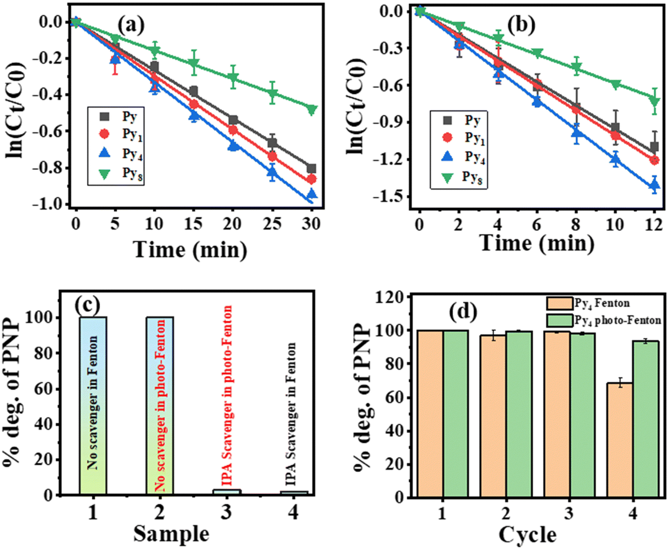 | ||
| Fig. 6 (a) Pseudo-first-order reaction kinetic (with error bars) plot of PNP degradation via Fenton reaction in the presence of different catalysts. Reaction conditions [H2O2] = 25 μmol, [catalyst] = 50 μL of 2 mg/2 mL, and [PNP] = 10 mg L−1. (b) pseudo-first-order reaction kinetics (with error bars) plot of PNP degradation via photo-Fenton reaction in the presence of different catalysts. Reaction conditions [H2O2] = 5 μmol, [catalyst] = 30 μL of 2 mg/2 mL, and [PNP] = 10 mg L−1. (c) The effect of radical scavenger in the degradation of PNP in Fenton and photo-Fenton reaction. (d) The reusability plot of the Py4 sample in the Fenton and photo-Fenton reaction (with error bars). | ||
| Sample | Fenton reaction with [H2O2] = 8.33 mM | Photo-Fenton reaction with [H2O2] = 1.66 mM | ||||
|---|---|---|---|---|---|---|
| TOF (μmol g−1 min−1) | H2O2 normalized TOF (mg−1 min−1 L) | Rate constant (min−1) | TOF (μmol g−1 min−1) | H2O2 normalized TOF (mg−1 min−1 L) | Rate constant (min−1) | |
| Py | 97.09 | 11.65 | 0.0236 | 230.60 | 138.91 | 0.0954 |
| Py1 | 57.35 | 6.88 | 0.0274 | 243.70 | 146.80 | 0.1000 |
| Py4 | 113.16 | 13.85 | 0.0480 | 254.50 | 153.31 | 0.1201 |
| Py8 | 46.28 | 5.556 | 0.0144 | 133.34 | 80.32 | 0.0581 |
The first control experiment was to expose an aqueous suspension of PNP and the catalyst particles to visible light irradiation from a cool white LED source. Very little PNP degradation (<4%) occurred under this condition. Next, PNP degradation under visible light irradiation was investigated in the presence of both catalyst and H2O2. Fig. M6(a) (ESI†) shows the effect of PNP degradation in the presence of the different amounts of Py4 catalyst with time. The optimum Py4 catalyst amount was 30 μL of 2 mg/2 mL catalyst suspensions. The amount of H2O2 also plays a crucial role in the photo-Fenton reaction. Fig. M7(a) (ESI†) shows the effect of 2.5, 5, 10, 15, 20, and 25 μmol of 0.5 M H2O2 for the PNP degradation on the Py4 catalyst. The optimum amount of 0.5 M H2O2 was 5 μmol. H2O2 amount higher than 5 μmol slowed down the PNP degradation process.
Fig. 6(b) shows the photo-Fenton degradation of PNP follows a pseudo-first-order kinetics. The third column of Table 2 displays the photo-Fenton TOF values for Py, Py1, Py4, and Py8 catalysts. The rate of photo-Fenton PNP degradation increased with doping till 4% Mo in FeS2. Thus, Py4 displays the best photo-Fenton TOF value for PNP degradation. Sample Py8 demonstrates a TOF value lower than observed on the Py sample. Table M5 (ESI†) compares the TOF and HTOF values of PNP degradation under photo-Fenton conditions over different catalysts reported in the literature (under neutral reaction conditions) with that of Py4. Py4 has the best HTOF value among the catalysts considered in this table.
Fig. 6(c) shows the percentage degradation of PNP in the presence and absence of IPA, a hydroxyl radical scavenger. Separate experiments were conducted under Fenton and photo-Fenton conditions. The Py4 sample was used in these scavenger experiments to investigate the reactive species responsible for the Fenton and the photo-Fenton reaction. Adding IPA almost stopped PNP degradation under both Fenton and photo-Fenton conditions. Therefore, the hydroxyl (˙OH) radicals are active species responsible for PNP degradation under both Fenton and photo-Fenton conditions.
Fig. 6(d) displays the recyclability of the Py4 sample because it has the best Fenton and photo-Fenton catalytic activity for PNP degradation. Under (dark) Fenton conditions there was hardly any change in the catalytic activity of Py4 until the end of the third cycle. However, in 4th cycle, the catalytic efficiency of Py4 decreased to 65.88% of the TOF activity observed in the first cycle. Fig. M8 (ESI†) compares the XRDs of sample Py4 before use and after four cycles of reuse under (dark) Fenton conditions. After reuse, the XRD displays all FeS2 peaks, but also has a new peak at 26.2°. The latter is attributed to the (111) plane of the Fe7S8 phase. The emergence of the Fe7S8 phase disrupts the Fenton cycle of the catalyst.
Contrary to this, the recyclability of the Py4 catalyst under photo-Fenton conditions was significantly better. After the 4th cycle, the photo-Fenton catalytic efficiency of Py4 samples dropped to only 95.12% of the activity observed in the 1st cycle. Thus, the photo-Fenton catalyst recyclability was appreciably better than under (dark) Fenton conditions. Table M3 (ESI†) gives complete (dark) Fenton and photo-Fenton recyclability data of sample Py4. Fig. M8 (ESI†) compares the XRDs of the fresh Py4 powder sample with that of the four-times recycled sample. The XRD of the reused Py4 displays only peaks of FeS2. Thus, the Py4 material remains stable even after repeated use under photo-Fenton reaction conditions, explaining its high recyclability. Table M5 (ESI†) also compares the recyclability of Py4 with previous investigations on neutral pH photo-Fenton catalysts. Please note that the MIL-100/Fe photo-Fenton catalyst (in Table M5, ESI†) uses a mercury vapor lamp as the light source without UV filter.33 Since UV radiation can also give hydroxyl radicals from H2O2, therefore, the reported photo-Fenton activity may not be due to the catalyst only.
Fig. M9(a) (ESI†) shows the survey spectrum of the recycled Py4 sample. There are some differences between the S 2p spectrum of the fresh and the recycled samples (Fig. M9(b), ESI†). Two peaks at 161.57 and 164.5 eV indicate the S− (−1 oxidation state) species is not present in the S 2p region of the recycled XPS spectrum.24 The area under the 2p3/2 and 2p1/2 peaks at 168.41 and 169.60 eV, due to the SO42−, have increased by 20%, indicating increased sulfate species on the reused Py4 sample. Fig. M9(c) (ESI†) shows peaks corresponding to 2p3/2 and 2p1/2 of Fe3+ at 713.74 eV and 727.5 eV, respectively.25 The areas under these Fe3+ peaks have increased (10%) relative to those in the spectrum of the fresh Py4 sample. Hence, there is an increase in the Fe3+ species on the reused Py4 surface, though this is still a small percentage. Fig. M9(d) (ESI†) shows the core level Mo 3d spectrum of the Py4 reused sample. There are two peaks at 228.44 and 230.44 eV corresponding to the 3d5/2 and 3d3/2 peaks of Mo in the +4-oxidation state.16 The Mo 3d spectrum also shows 3d5/2 and 3d3/2 peaks at 232.67 and 235.29 eV consistent with Mo in the +6-oxidation state.26 Thus, the recycled Py4 sample (in contrast to the fresh Py4 sample) shows the presence of Mo in both +4 and +6 oxidation states. The presence of Mo6+ on the reused Py4 surface gives credence to the proposed reaction mechanism (see Section 3.4). The Fe and Mo leaching concentrations were determined by the ICP-MS technique. We found that the concentration of Fe and Mo elements in the tested Py4 sample decreased by nearly 12.73% and 9.5% at the end of the 4th cycle. These percentages are relative to the elemental content of the fresh Py4 sample. Thus, the decrease in photocatalytic efficiency to 95.12% by the fourth cycle of reuse is because of Fe and Mo leaching from the photocatalyst during the reuse of the sample.
3.4 Possible Fenton and photo-Fenton mechanism
Fenton reaction involves the oxidation of Fe2+ to Fe3+ (on the catalyst) during the reductive cleavage of H2O2. The latter generates hydroxyl radicals, which effectively oxidize the target organic pollutant. Effective regeneration of Fe2+ from Fe3+ on the catalyst's surface is the key to Fenton catalyst recyclability, but this step is much slower than the forward reaction. As explained earlier, the correlation between DFT calculations and XRD results shows that Mo substitutes Fe in the FeS2 lattice. Furthermore, Mo atoms substituting Fe2+ in FeS2 are in a +4-oxidation state.The schematic in Fig. 7(a) shows the proposed Fenton catalysis mechanism. The Fenton activity is due to Fe2+ reducing H2O2. The replacement of the Fe2+ by Mo4+ results in a loss of (Fe2+ to Fe3+) activity but also enhances the Fe3+ to Fe2+ reduction rate. The following set of reactions34 describes this phenomenon.
| 2Fe3+ + Mo4+ → 2Fe2+ + Mo6+ | (R1) |
| Mo6+ + 2e− + 2H2O2 → Mo4+ + 2H2O + O2 | (R2) |
 | ||
| Fig. 7 Proposed (a) Fenton and (b) photo-Fenton mechanism of PNP degradation in the Mo-doped FeS2. | ||
In reaction (R1), Mo4+ reduces Fe3+ to Fe2+, while in the second reaction, the reduced Mo4+ is recovered by oxidizing H2O2. Hence, Mo substituting Fe decreases the forward Fenton reaction activity but enhances the regeneration of the catalyst. The two effects are opposed to each other. Thus, Py4 demonstrates the optimal Fenton PNP degradation activity. Sample Py8 displays lower Fenton activity because of excess Mo-doping.
As mentioned earlier, DFT calculations predict that Mo-doping would substitute a Fe atom in FeS2, along with lattice expansion. These calculations also qualitatively showed that the Mo-doping energy state in the FeS2 bandgap region would reduce its bandgap. Experimental results also show a bandgap reduction after Mo-doping. Besides supplying electrons for the Fe3+ to Fe2+ back reaction, the dopant Mo possibly may also influence the adsorption behaviour of the photocatalyst surface towards H2O2.30,31 Additionally, XPS results show that VB and CB positions shift to lower NHE scale values. An analysis of the PDOS and TDOS of the Mo-doped FeS2 relative to the undoped FeS2 model shows that a Mo 4d dopant state reduces the band gap from the VB side. Furthermore, PL results show that Py4 has slower recombination kinetics than other FeS2 samples studied due to enhanced charge separation. In accordance with this, sample Py4 also demonstrates the best photo-Fenton activity.
Given this background, we propose the following photo-Fenton PNP degradation mechanism. The scheme in Fig. 7(b) depicts the proposed photo-Fenton mechanism. Catalyst surface Fe2+ reduction of H2O2 generates hydroxyl radicals. Relevant IPA scavenger experiment observations show that hydroxyl radicals generated in this process oxidize PNP. Irradiating the Mo-doped FeS2 catalyzed system with cool white LED light photoexcites the electrons from the VB to the CB of the material. The photo-excited electron reduces the Fe3+ to Fe2+, regenerating the catalyst. The photo-excitation process converts adjacent Fe2+ to Fe3+ ions on the VB side. Mo4+ dopants reduce these Fe3+ to Fe2+ cations. Mo4+ is regenerated from Mo6+ by H2O2 oxidation on it. Mo6+ generation was confirmed by the recycled Py4 sample XPS spectra. As mentioned earlier, Mo-doping ensures better charge separation than otherwise.35
4 Conclusions
In this work, undoped and Mo-doped iron pyrite materials were synthesized using a solvothermal method. XRD and DFT investigations showed that the dopant Mo substituted Fe in the FeS2 lattice. Furthermore, XPS and DFT density of states analysis indicated Mo contribution to the VB of the doped FeS2. PL spectra showed the slowest recombination kinetics for the Py4 sample. Among the prepared FeS2 samples, Py4 (4 mol% Mo-doped) demonstrated the best (dark) Fenton and photo-Fenton catalytic activity for PNP degradation. Furthermore, photo-Fenton PNP TOF degradation values of all samples were substantially better than their Fenton TOF values. Another vital aspect was the significantly better recyclability of the catalysts under visible light photo-Fenton conditions. It appears that the Mo4+ dopant enhances the reusability of the catalyst by reducing the Fe3+ produced to Fe2+ during the Fenton and photo-Fenton process while itself getting regenerated by H2O2 oxidation. Since Mo4+ itself does not reduce H2O2, its substitution of Fe in FeS2 would reduce the forward H2O2 reduction activity of the material. Besides this, only 8.33 mmol per liter and 1.66 mmol per liter. H2O2 was required for optimum Fenton and photo-Fenton PNP degradation. These H2O2 levels are appreciably lower than other recent reports. Catalyst Py4 appears to have the best H2O2 normalized TOF value for photo-Fenton PNP degradation.Data availability
The data supporting this article have been included as part of the ESI.†Conflicts of interest
There are no conflicts to declare.Acknowledgements
Maheswari Yadav acknowledges the financial support (JRF) received from IIT (BHU). The authors are also thankful to CCIS IIT (BHU) for computational facilities. We also acknowledge the Department of Chemistry for using the PL facility there. The authors thank CIF, IIT(BHU) for materials characterization facilities.References
- M. Pera-Titus, V. García-Molina, M. A. Baños, J. Giménez and S. Esplugas, Degradation of chlorophenols by means of advanced oxidation processes: a general review, Appl. Catal., B, 2004, 47(4), 219–256 CrossRef CAS
.
- H. Ren, X. Jin, C. Li, T. Li, Y. Liu and R. Zhou, Rosmarinic acid enhanced Fe(III)-mediated Fenton oxidation removal of organic pollutants at near neutral pH, Sci. Total Environ., 2020, 736, 139528 CrossRef CAS PubMed
- J. Xiao, C. Wang, S. Lyu, H. Liu, C. Jiang and Y. Lei, Enhancement of Fenton degradation by catechol in a wide initial pH range, Sep. Purif. Technol., 2016, 169, 202–209 CrossRef CAS
- Y. Lee and W. Lee, Degradation of trichloroethylene by Fe(II) chelated with cross-linked chitosan in a modified Fenton reaction, J. Hazard. Mater., 2010, 178(1–3), 187–193 CrossRef CAS PubMed
- S. A. Messele, C. Bengoa, F. E. Stüber, J. Giralt, A. Fortuny, A. Fabregat and J. Font, Enhanced degradation of phenol by a Fenton-like system (Fe/EDTA/H2O2) at circumneutral pH, Catal., 2019, 9(5), 474 CrossRef CAS
- R. Zhou, N. Shen, J. Zhao, Y. Su and H. Ren, Glutathione-coated Fe3O4 nanoparticles with enhanced Fenton-like activity at neutral pH for degrading 2,4-dichlorophenol, J. Mater. Chem. A, 2018, 6(3), 1275–1283 RSC
- X. Da, D. Tang, L. Wang and J. Ma, Glutathione promoted Fenton degradation: a cocatalyst based on the -HS/-S-S- cycle with hydroxyl radicals, Environ. Sci.: Water Res. Technol., 2020, 6(3), 515–522 RSC
- S. Bae, D. Kim and W. Lee, Degradation of diclofenac by pyrite catalyzed Fenton oxidation, Appl. Catal., B, 2013, 134, 93–102 CrossRef
- T. Liu, N. Chen, Y. Deng, F. Chen and C. Feng, Degradation of p-nitrophenol by nano-pyrite catalyzed Fenton reaction with enhanced peroxide utilization, RSC Adv., 2020, 10(27), 15901–15912 RSC
- C. Liu, H. Yi, B. Yang, F. Jia and S. Song, Activation of Fenton reaction by controllable oxygen incorporation in MoS2–Fe under visible light irradiation, Appl. Surf. Sci., 2021, 566, 150674 CrossRef CAS
- D. Huang and J. Zhao, Speeding up Fenton reactions with a heterogeneous inorganic co-catalyst, Chem., 2020, 6(7), 1512–1514 CAS
- S. Venkateshalu, P. G. Kumar, P. Kollu, S. K. Jeong and A. N. Grace, Solvothermal synthesis and electrochemical properties of phase pure FeS2 for supercapacitor applications, Electrochim. Acta, 2018, 290, 378–389 CrossRef CAS
- D. Wang, Q. Wang and T. Wang, Shape controlled growth of pyrite FeS2 crystallites via a polymer-assisted hydrothermal route, CrystEngComm, 2010, 12(11), 3797–3805 RSC
- J. P. Perdew, K. Burke and M. Ernzerhof, generalized gradient approximation made simple, Phys. Rev. Lett., 1996, 77(18), 3865 CrossRef CAS PubMed
- A. K. De, N. Kamal, U. Kumar, N. Jatav and I. Sinha, The bandgap of sulfur-doped Ag2O nanoparticles, Phys. Chem. Chem. Phys., 2022, 25(3), 2320–2330 RSC
- H. B. Wang, J. Q. Wang, R. Zhang, C. Q. Cheng, K. W. Qiu, Y. J. Yang, J. Mao, H. Liu, M. Du, C. K. Dong and X. W. Du, Bionic design of a Mo(IV)-doped FeS2 catalyst for electroreduction of dinitrogen to ammonia, ACS Catal., 2020, 10(9), 4914–4921 CrossRef CAS
- L. H. Ahrens, The use of ionization potentials Part 1. Ionic Radii of the elements, Geochim. Cosmochim. Acta, 1952, 2(3), 155–169 CrossRef CAS
- R. D. Shannon, Revised effective ionic radii and systematic studies of interatomic distances in halides and chalcogenides, Acta Crystallogr., Sect. A: Cryst. Phys., Diffr., Theor. Gen. Crystallogr., 1976, 32(5), 751–767 CrossRef
- A. Dolgonos, T. O. Mason and K. R. Poeppelmeier, Direct Optical band gap measurement in polycrystalline semiconductors: a critical look at the Tauc Method, J. Solid State Chem., 2016, 240, 43–48 CrossRef CAS
- Z. López-Cabaña, C. M. S. Torres and G. González, Semiconducting properties of layered cadmium sulphide-based hybrid nanocomposites, Nanoscale Res. Lett., 2011, 6, 1–8 CrossRef PubMed
- S. Middya, A. Layek, A. Dey and P. P. Ray, Synthesis of nanocrystalline FeS2 with increased band gap for solar energy harvesting, J. Mater. Sci. Technol., 2014, 30(8), 770–775 CrossRef CAS
- H. Sun and P. Tang, Visible-light driven FeS2 nanosized photocatalysts prepared by solvothermal method, Adv. Mater. Res., 2012, 486, 55–59 CAS
- Y. Ahmed, J. Zhong, W. Wang, L. Wang, Z. Yuan and J. Guo, Simultaneous removal of antibiotic-resistant bacteria, antibiotic resistance genes, and micropollutants by FeS2@GO-based heterogeneous photo-Fenton process, Environ. Sci. Technol., 2022, 56(21), 15156–15166 CrossRef CAS PubMed
- H. Liu, F. Liu, J. Zhang, J. Zhou, W. Bi, J. Qin, Q. Hou, Y. Ni, S. Xu and C. Yang, Degradation of methyl orange by pyrite activated persulfate oxidation: mechanism, pathway, and influences of water substrates, Water Sci. Technol., 2022, 85(10), 2912–2927 CrossRef CAS PubMed
- Y. Cai, Y. Pan, J. Xue, Q. Sun, G. Su and X. Li, Comparative XPS study between experimentally and naturally weathered pyrites, Appl. Surf. Sci., 2009, 255(21), 8750–8760 CrossRef CAS
- H. W. Wang, P. Skeldon and G. E. Thompson, XPS Studies of MoS2 formation from ammonium tetrathiomolybdate solutions, Surf. Coat. Technol., 1997, 91(3), 200–207 CrossRef CAS
- F. Pei, S. Wu, G. Wang, M. Xu, S. Y. Wang, L. Y. Chen and Y. Jia, Electronic and optical properties of noble metal oxides M2O (M = Cu, Ag, and Au): first-principles study, J. Korean Phys. Soc., 2009, 55(3), 1243–1249 CrossRef CAS
- D. Banjara, Y. Malozovsky, L. S. Franklin and D. Bagayoko, First-principles studies of electronic, transport and bulk properties of pyrite FeS2, AIP Adv., 2018, 8(2), 025212 CrossRef
- J. Cai and M. R. Philpott, Electronic structure of bulk and (001) surface layers of pyrite FeS2, Comput. Mater. Sci., 2004, 30, 358–363 CrossRef CAS
- J. Xie, S. Wu, C. Luo, J. Zou, Y. Lin, S. He and C. Yang, Modulating Electronic Structure of Active Sites on Iron-Based Nanoparticles Enhances Peroxymonosulfate Activation, Appl. Catal., B, 2024, 354, 124138 CrossRef CAS
- J. Zou, S. Wu, Y. Lin, S. He, Q. Niu, X. Li and C. Yang, Electronic Phosphide-Support Interactions in Carbon-Supported Molybdenum Phosphide Catalysts Derived from Metal-Organic Frameworks, Nano Lett., 2023, 23(23), 10955–10963 CrossRef CAS PubMed
- A. K. Hassan, M. A. Atiya and Z. A. Mahmoud, Photo-Fenton-like Degradation of Direct Blue 15 Using Fixed Bed Reactor Containing Bimetallic Nanoparticles: Effects and Box–Behnken Optimization, Environ. Technol. Innovation, 2022, 28, 102907 CrossRef CAS
- M. Nekoeinia, S. Yousefinejad, F. Hasanpour and M. Yousefian-Dezaki, Highly Efficient Catalytic Degradation of P-Nitrophenol by Mn3O4·CuO Nanocomposite as a Heterogeneous Fenton-like Catalyst, J. Exp. Nanosci., 2020, 15(1), 322–336 CrossRef CAS
- T. Tang, B. Jin and P. Zhao, Preparation of the photo-Fenton agent MIL-100 (Fe) with high performance in the degradation of nitro explosives, New J. Chem., 2023, 47(18), 8566–8577 RSC
- B. Zhao, G. Mele, I. Pio, J. Li, L. Palmisano and G. Vasapollo, Degradation of 4-Nitrophenol (4-NP) Using Fe–TiO2 as a Heterogeneous Photo-Fenton Catalyst, J. Hazard. Mater., 2010, 176(1–3), 569–574 CrossRef CAS PubMed
- M. A. McKibben and H. L. Barnes, Oxidation of Pyrite in Low Temperature Acidic Solutions: Rate Laws and Surface Textures, Geochim. Cosmochim. Acta, 1986, 50(7), 1509–1520 CrossRef CAS
- J. De Laat and H. Gallard, Catalytic decomposition of hydrogen peroxide by Fe(III) in homogeneous aqueous solution: mechanism and kinetic modeling, Environ. Sci. Technol., 1999, 33(16), 2726–2732 CrossRef CAS
- Y. Yang, Q. Wang, R. Aleisa, T. Zhao, S. Ma, G. Zhang, T. Yao and Y. Yin, MoS2/FeS nanocomposite catalyst for efficient Fenton reaction, ACS Appl. Mater. Interfaces, 2021, 13(44), 51829–51838 CrossRef CAS PubMed
- M. Xing, W. Xu, C. Dong, Y. Bai, J. Zeng, Y. Zhou, J. Zhang and Y. Yin, Metal sulfides as excellent co-catalysts for H2O2 decomposition in advanced oxidation processes, Chem., 2018, 4(6), 1359–1372 CAS
- L. Zeng, J. Gong, J. Dan, S. Li, J. Zhang, W. Pu and C. Yang, Novel visible light enhanced pyrite-Fenton system toward ultrarapid oxidation of p-nitrophenol: catalytic activity, characterization, and mechanism, Chemosphere, 2019, 228, 232–240 CrossRef CAS PubMed
Footnote |
| † Electronic supplementary information (ESI) available. See DOI: https://doi.org/10.1039/d4cp00793j |
| This journal is © the Owner Societies 2024 |