Response of helielectric nematics under an in-plane electric field
Satoshi
Aya
 *ab,
Hao
Xu
ab,
Huaqian
Long
ab,
Muhan
Yiliu
ab,
Yu
Zou
ab and
Mingjun
Huang
 ab
ab
aSouth China Advanced Institute for Soft Matter Science and Technology (AISMST), School of Emergent Soft Matter, South China University of Technology, Guangzhou 510640, China
bGuangdong Provincial Key Laboratory of Functional and Intelligent Hybrid Materials and Devices, South China University of Technology, Guangzhou 510640, China. E-mail: satoshiaya@scut.edu.cn
First published on 3rd April 2024
Abstract
In traditional chiral nematic liquid crystals, the apolar cholesterics, the dielectric effect is the main driving force for responding to an electric field. The emerging polar chiral nematics, dubbed helielectric nematics, are the polar counterparts of the cholesterics. The head-to-tail symmetry breaking of the new matter state enables it to respond sensitively to the polarity of an electric field. Here, we report on the observation of a sequential polar winding/unwinding process of polarization helices under an electric field applied perpendicular to the helical axes, which behaves distinctly from the unwinding of the apolar cholesteric helices. Understanding the helix-unwinding behaviors provides insights for developing switchable devices based on helielectric nematics.
Introduction
The chiral nematic liquid-crystalline (LC) state, the so-called cholesteric (Ch) LCs, is characterized by its self-assembled helical superstructure with a chiral arrangement of molecules that form quasi-layers.1–3 The matter state is ubiquitous and can be found in a wide range of natural and synthetic systems. The fundamental constituents are usually anisotropically-shaped particles such as rod- and bend-shaped molecules, whose local ensemble-averaged orientation of molecules (the so-called director![[n with combining right harpoon above (vector)]](https://www.rsc.org/images/entities/i_char_006e_20d1.gif) ) is head-to-tail symmetric, i.e.,
) is head-to-tail symmetric, i.e., ![[n with combining right harpoon above (vector)]](https://www.rsc.org/images/entities/i_char_006e_20d1.gif)
![[triple bond, length as m-dash]](https://www.rsc.org/images/entities/char_e002.gif) −
−![[n with combining right harpoon above (vector)]](https://www.rsc.org/images/entities/i_char_006e_20d1.gif) . This apolar orientational symmetry is usually characterized by the second-order Legendre polynomial (P2(cos
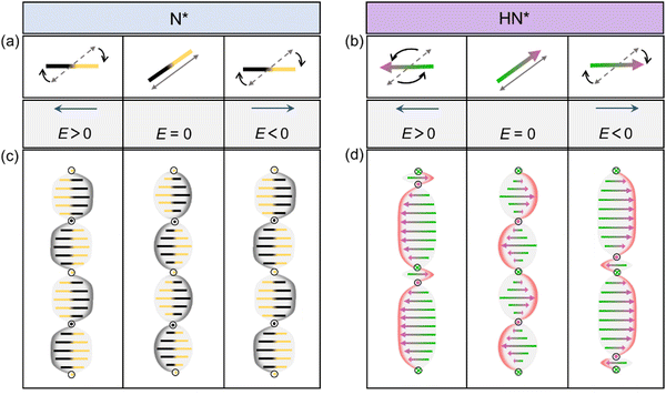
. This apolar orientational symmetry is usually characterized by the second-order Legendre polynomial (P2(cos![[thin space (1/6-em)]](https://www.rsc.org/images/entities/char_2009.gif) θ)). This symmetry leads to the dielectric response of Ch LCs under an electric field, where the orientation of the director quadratically couples to the electric field. It means that the director does not sense the directionality of the electric field but chooses the fastest way to align either parallel or antiparallel to the electric field (Fig. 1a). Thanks to the excellent electro-optic properties and fast electric-field tunability, Ch LCs have been the central target in establishing vast next-generation LC technologies such as liquid-matter-based sensors,4 security5 and anti-counterfeiting applications6 photonic systems including optical modulators,7 planar optics8 and lasing devices.9
θ)). This symmetry leads to the dielectric response of Ch LCs under an electric field, where the orientation of the director quadratically couples to the electric field. It means that the director does not sense the directionality of the electric field but chooses the fastest way to align either parallel or antiparallel to the electric field (Fig. 1a). Thanks to the excellent electro-optic properties and fast electric-field tunability, Ch LCs have been the central target in establishing vast next-generation LC technologies such as liquid-matter-based sensors,4 security5 and anti-counterfeiting applications6 photonic systems including optical modulators,7 planar optics8 and lasing devices.9
Recently, several new classes of LCs have been discovered, e.g., ferroelectric nematic,10–15 polar chiral Ch (dubbed helielectrics)16–20 and ferroelectric smectic-A21–23 states. In contrast to traditional nematic, Ch and smectic-A LCs that are macroscopically apolar, the emerging matter states demonstrate strong macroscopic polarity enabled by introducing large dipoles into the molecular constituents.10,13,24–27 Among them, the polarization vector ![[P with combining right harpoon above (vector)]](https://www.rsc.org/images/entities/i_char_0050_20d1.gif) is nearly along the long axis of
is nearly along the long axis of ![[n with combining right harpoon above (vector)]](https://www.rsc.org/images/entities/i_char_006e_20d1.gif) , so
, so ![[n with combining right harpoon above (vector)]](https://www.rsc.org/images/entities/i_char_006e_20d1.gif) and
and ![[P with combining right harpoon above (vector)]](https://www.rsc.org/images/entities/i_char_0050_20d1.gif) are completely coupled. In other words, the apolar and polar orientational orders, characterized by P2(cos
are completely coupled. In other words, the apolar and polar orientational orders, characterized by P2(cos![[thin space (1/6-em)]](https://www.rsc.org/images/entities/char_2009.gif) θ) and the first-order Legendre polynomial (P1(cos
θ) and the first-order Legendre polynomial (P1(cos![[thin space (1/6-em)]](https://www.rsc.org/images/entities/char_2009.gif) θ)), respectively, coexist in the emerging polar states.24 For simplicity and convenience, we use the polarization vector P to describe the directionality of the local polarization hereafter. The unique symmetry endows the systems with mixed polar and dielectric responses to an electric field. At low amplitudes, the polar response, which exhibits a linear coupling between
θ)), respectively, coexist in the emerging polar states.24 For simplicity and convenience, we use the polarization vector P to describe the directionality of the local polarization hereafter. The unique symmetry endows the systems with mixed polar and dielectric responses to an electric field. At low amplitudes, the polar response, which exhibits a linear coupling between ![[P with combining right harpoon above (vector)]](https://www.rsc.org/images/entities/i_char_0050_20d1.gif) and the electric field
and the electric field ![[E with combining right harpoon above (vector)]](https://www.rsc.org/images/entities/i_char_0045_20d1.gif) , i.e., electric torque
, i.e., electric torque  , dominates.12,20,28,29 Compared to the dielectric response in traditional Ch LCs (Fig. 1a), the polar response differentiates the directionality of the electric field and favors the alignment of local polarization parallel to the electric field (Fig. 1b). This would result in an asymmetric deformation of polar helices in polar and chiral nematic LCs (Fig. 1d), dubbed helielectrics, while traditional Ch LCs exhibit a symmetric response of the helices (Fig. 1c). It is shown that polar switching significantly lowers the driving voltage for the LC reorientation down to the order several tens of mV μm−1.20,28 It provides an exciting opportunity to develop ultralow electricity-consumption LC devices. Yet, there are only a few studies investigating the dynamic processes of the polar response. It is challenging to understand how the polarization reorientation processes would affect the structure of the new polar states.
In this article, we report on a systematic observation of polar responses in the helielectrics with different numbers of polar helices. Under a small direct-current (DC) electric field, we reveal that the polarization helix undergoes multiple stages of unwinding and winding structural transitions upon the field being turned on and off, respectively. This scenario is absent in traditional Ch LCs and offers a novel pathway for controlling LC structures.
Experimental section
Sample preparation
The helielectric mixture was generated by adding commercial chiral dopants R811 at a concentration of 1.1 wt% to the homemade ferroelectric nematic LC 4-((4-nitrophenoxy)carbonyl) phenyl 2,4-dimethoxybenzoate (RM734). These two solid materials were dissolved in chloroform, and then the solution was sonicated to make it homogeneously dispersed. Finally, the solvent was volatilized at 55 °C until completely removed. When the temperature of RM734/R811 mixtures was controlled below 133 °C, the helielectric nematic (HN*) phase appeared spontaneously. According to the results of the reciprocal of the helical pitch as a function of the concentration of R811 (HTP ≈ 14.2 μm−1),30,31 the helical pitch p of the HN* mixture we used is about 6.7–7.2 μm. The apolar helical structures in Ch LCs were obtained by mixing a chiral agent with a mass concentration of 1.1% in 5 CB and RM734/R811 mixtures at high temperatures.LC cell preparation
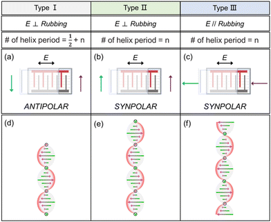
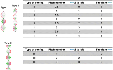
We used an alignment agent, KPI-3000 (Shenzhen Haihao Technology Co. Ltd), to facilitate planar alignment. The surfaces of two glass plates coated with KPI-3000 by rubbing would provide the pre-tilting condition, aligning the surface polarization Psuf parallel to the rubbing direction R (Psuf//−R). This corresponds to the polar surface treatment. To examine the coupling between the bulk polarization P and the external direct-current (DC) electric field E, we designed three types of LC cells combining different combinations of the directions of P and E: (i) type I—antiparallel Psuf on upper and bottom surfaces by antiparallelly-rubbing the two surfaces, which are perpendicular to the electric field direction (E⊥Psuf or −Psuf; Fig. 2a). Under this condition, the number of the helielectric polar helices is n + 1/2 (n is a natural number; Fig. 2b); (ii) type II—syn-parallel Psuf by rubbing both surfaces in the same direction, which is perpendicular to E (E⊥Psuf; Fig. 2c). Under this condition, the number of the helielectric polar helices is n (Fig. 2e); (iii) the surface treatment and the number of helielectric helices in type III are the same as those in type II. The rubbing direction is parallel or antiparallel to E ((E‖Psuf or −Psuf); Fig. 2c, f). In wedged LC cells, the helielectric pitch correlates with the periodicity of Grandjean–Cano lines as p = Ltan![[thin space (1/6-em)]](https://www.rsc.org/images/entities/char_2009.gif) α;32 the number of helielectric helices continuously increases with increasing sample thickness (from 0 to 30 μm).
α;32 the number of helielectric helices continuously increases with increasing sample thickness (from 0 to 30 μm).
Observation of in-plane electro-optics of the polarization helices
We tracked the electro-optic response of the HN* structures by using polarizing light microscopy (PLM) in the abovementioned three types of LC cells to analyze the variations in the polarization field. The ITO layer that drives an in-plane electric field consists of an interdigital comb-gap between two adjacent electrodes, measuring 500 μm. The DC electric field was generated by a function generator and its direction was changed according to the experimental conditions as shown in Fig. 2.Numerical simulation of field-induced reorientation of polarization
As recently revealed in ref. 33 and 34 an extended Oseen–Frank free-energy functional comprising the elastic, flexoelectric, polarization gradient, depolarization and surface anchoring free energies is used for conducting simulations on the field-induced reorientation of polarizations. As the field deformation, except for the twist, is negligible based on experimental observation, the flexoelectric, polarization gradient and depolarization free energy terms are omitted in the following calculations. Then, the free-energy density is written as| f = felastic + fanchor + fE, |
The first term represents the Frank elastic energy. K11, K22, and K23 represent the splay, twist and bend elastic constants, respectively. n, q0, qref, ν, W, P and E are the director, the wavenumber of helices, the angle between the easy axis of anchoring and the normal of surface, the surface normal vector, the anchoring strength, the local polarization and the electric field, respectively. P is assumed to be parallel to n. The last term fE represents the linear coupling between the local polarization to the electric field. Based on the free energy, we calculate the time evolution of the polarization field before and upon the application of electric fields according to the time-dependent partial differential Ginzburg–Landau (TDGL) equation.35 In our simulations, we set the parameters as below: the simulation parameters are as follows: K11 = K22 = K23 = 2 pN, cell thickness = 30 μm, W = ∞, θref = 90°, the magnitude of the polarization P0 = 6 μC cm−2, q0 = 2π/15 μm−1, Δt = 0.02 ms, and the effective rotational viscosity γ = 9.6 mPa s.
Results and discussion
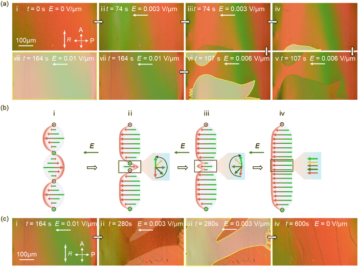
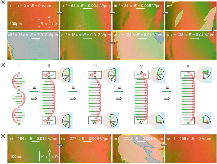
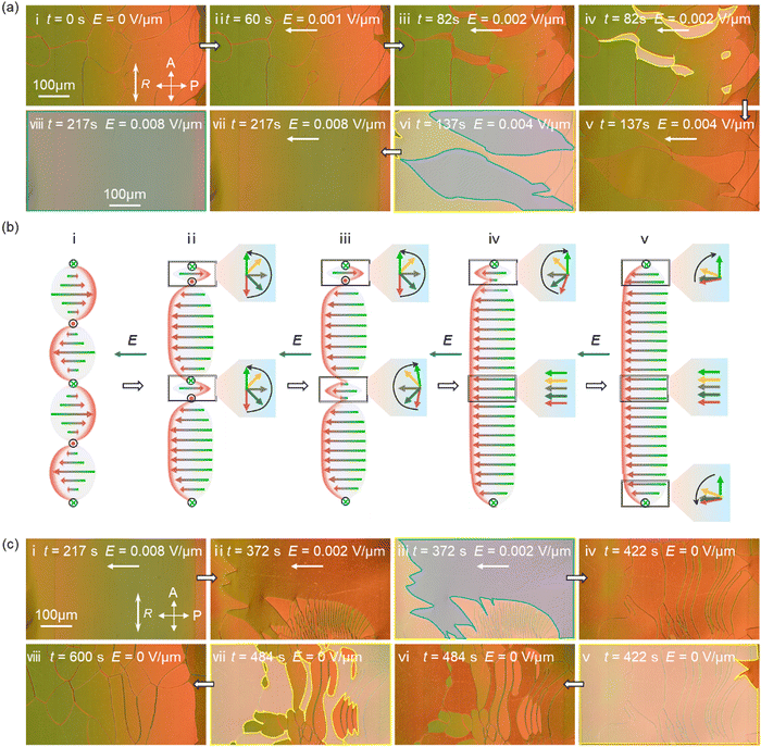
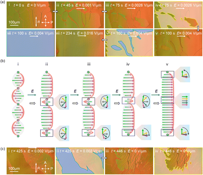
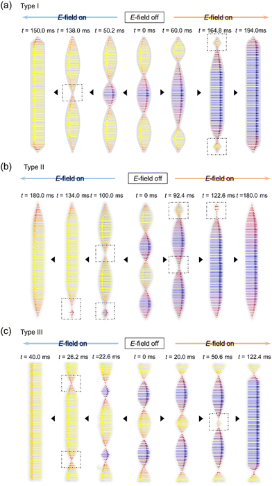
Using the aforementioned LC cell configurations (Fig. 2a–c), we investigated how the polar helices in the HN* state respond to an external DC field. By controlling the sample thickness, we varied the number of the polar helices confined in the LC cells and explored the difference. As representative examples, we explain the electric-field response for helielectrics under type I, II, III configurations (Fig. 3–8). For type I configuration, we demonstrate the results by applying a DC electric field to either the left (Fig. 3) or right (Fig. 4) directions to a 1.5-pitch polar helix. The electric fields are perpendicular to the surface anchored polarizations. For type II configuration, we demonstrate the results by applying a DC electric field to either the left (Fig. 5) or right (Fig. 6) directions to a 2-pitch polar helix. The electric fields are perpendicular to the surface anchored polarizations. For type III configuration, we demonstrate the results by applying a DC electric field to either the left (Fig. 3) or right (Fig. 4) directions to a 2-pitch polar helix. The electric fields are parallel to the surface-anchored polarizations.When the pitch number was a half integer as in Fig. 3 (1.5-pitch helices; type I configuration), we observed the nucleation of untwisted domains upon increasing the DC electric fields. When the DC field is applied to the left of the helix where the DC field is parallel to the average polarization directions near the bottom and top half pitches, the polarization field of the polar helices first deforms and undergoes a slight color variation (Fig. 3a, i and ii). This process corresponds to the asymmetric redistribution of the polarization field (Fig. 3b, i and ii), which was later investigated using confocal fluorescent polarizing light microscopy. While the middle half pitch shrinks, the two half pitches near the surfaces lengthen due to coupling with the polarization field. This is a unique electric-field-induced reorientational process for the polar helices. The apolar helices, like the Ch state, respond dielectrically to the electric field, leading to a symmetric biasing of the director along the DC field (Fig. 1a, b). When the DC electric field reaches 0.003 V μm−1, a nucleation of the unwound state occurs. This corresponds to the unwinding of the initial twist of the polarization field by covering the space with the polarization orientation state in the middle half pitch of the LC cell (Fig. 3a, iii and iv). Noteworthily, this ultralow electric field is beneficial for reducing the electric driving voltage of LC devices down to the millivolts range by choosing an appropriate electrode distance. When the electric field was removed, the nucleated domains followed the reverse path back to the original state (Fig. 3c) unless the unwound domains fully covered the field of the view. The only difference in the backward process is the additional appearance of a transient stripe pattern, which occurs just after the backward nucleation from the unwound to the helielectric state with 1.5 helices (Fig. 3c, i–iv). A completely different process occurs when the DC field is reversed to the right direction of the helix (Fig. 4). In contrast to the process shown in Fig. 3, the middle half pitch undergoes an expansion and the two half pitches near the surfaces shrink. On increasing the DC electric field, the localization of the twist in the two half pitches near the surfaces becomes stronger. Over a critical electric field at about 0.006 V μm−1, nucleation occurs. This process is attributed to the helix unwinding from the two half pitches because the localized twists become energetically unfavorable.
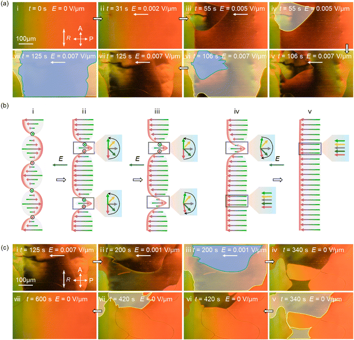
Let us analyze the results for type II configuration with 2-pitch helices, where the DC electric field is applied perpendicular to surface-anchored polarizations. In this case, we observed the nucleation of untwisted domains twice upon increasing the DC electric fields. When the DC field is applied to the left (Fig. 5a), the second and fourth bottom half pitches expand, whereas the first top and third half pitches shrink due to the polarization-field coupling. Unlike the situation with 1.5-pitch helices in type I configuration, one of the shrank half pitches is located near the surface and the other is close to the middle in bulk. Since the two domains differ in their threshold to unwind, the PLM observation directly visualizes the unwinding nucleation twice at about 0.002 V μm−1 and 0.004 V μm−1, respectively (Fig. 5b, iii–vi). In the backward process after switching off the electric field, we again observe the winding nucleation processes twice, returning back to the original state (Fig. 5c). Applying a DC field to the right mirrors the symmetric process observed when applying a DC field to the left. This time, the second and fourth bottom half pitches shrink, whereas the first top and third half pitches expand (Fig. 6).
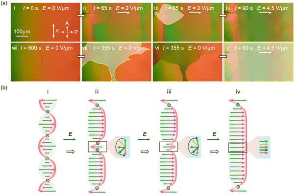
Finally, let us we explain the results for type III configuration with 2-pitch helices, where the DC electric field is applied parallel to surface anchored polarizations. When a DC field is applied syn-parallel to both the surface polarizations (i.e., DC field to left; Fig. 7), three half pitches (i.e., the first, third and fifth half pitches) expand, and the rest shrink near the middle of the cell (Fig. 5a, b). In this case, we also observe the nucleation of unwinding twice (Fig. 7a). The first unwinding is attributed to a process where one of the two half pitches shrinks, while the remaining half pitch slides (Fig. 7b, ii–iv). The second unwinding corresponds to the unwinding of the remaining half pitch (Fig. 7b, iv and v). Switching the DC field to be antiparallel to both the surface polarizations (i.e., DC field to the right; Fig. 8) results in another situation where the first, third and fifth half pitches shrink and the rest expand. For this time, only one nucleation occurs, corresponding to the unwinding of the third middle half pitch (Fig. 8a). On the surface, two shrunk half pitches near the surfaces cannot be unwound or flipped due to the strong anchoring of the polarization up to 4.5 V μm−1 (Fig. 8b).
For other situations with different pitches in type I, II, and III configurations, a clear rule is observed, as summarized in Fig. 9a, through a systematic investigation of the relationship. The number of nucleations observed under each condition is fully consistent with the proposed unwinding scenarios observed experimentally (Fig. 3–8). For type I configuration with a half-integer number (n) of polar helices and the anchoring axis perpendicular to the DC field, the number of the nucleation is n − 1/2 for the left-direction DC field and n − 1/2 for the right-direction DC field (Fig. 9). For type II configuration with an integer number of polar helices and anchoring axis perpendicular to the DC field, the number of the nucleation is n for both the left- and right-direction DC fields (Fig. 9). For type III configuration with an integer number of polar helices and anchoring axis parallel to the DC field, the number of the nucleation is n for the left-direction DC field and n − 1 for the right-direction DC field (Fig. 9).
All these unwinding behaviors can be well reproduced or predicted by simulations based on an extended Oseen–Frank theory accounting for the polar interaction with the electric field. Fig. 10 displays some representative simulation results about the unwinding behaviors under the electric field in type I and II configurations. In type I configuration, the simulated results for a 1.5-pitch system are consistent with the experimentally obtained models, as shown in Fig. 10a. A slight difference is that the unwinding does not occur in the middle of the cell but near surfaces. The expanded domains with the syn-parallel alignment of polarizations along the electric field push the shrinking domains with the antiparallel alignment of polarizations toward the electric field toward the surfaces. The strong surface anchoring with perpendicular polarizations to the electric field favors the local unwinding happening there. Similarly, in type II configuration with a 2-pitch system, Fig. 10b demonstrates that the first unwinding occurs near the middle of the cell, where the middle half helix with its polarization antiparallel to the electric field is compressed. The second unwinding then occurs near the surfaces. Fig. 10c shows the unwinding behaviors in type III configuration with a 2-pitch system. Although unwinding occurs at two places located symmetrically near the cell center, they do not happen at the same time because the electric field applied to the cell in the experiment is localized near the bottom surface, which creates a gradient of the electric field along the z axis.
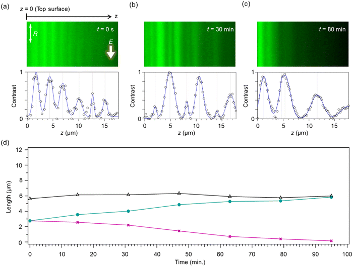
To obtain direct evidence of the asymmetric dilation/shrinkage of the polarization helices under a DC field, we used confocal fluorescence polarizing microscopy (CFPM). Fig. 11 shows cross-sections of the HN* helices in type III configuration along the z axis. The helical pitch is 5.6 μm. We use a very small DC electric field (0.02 V μm−1) because the unwinding dynamics are so slow that we can track the time evolution. When the DC field is off, distances between neighboring black lines, corresponding to the half pitch, are 2.8 μm and the same for all the neighboring pairs (Fig. 11a). This confirms that field-free HN* helices are distorted. When the DC field is applied syn-parallel to the rubbing direction, the distance between neighboring black lines exhibits a repetitive dilation and shrinkage (Fig. 11b, c). For the half pitches with the polarization orientation along the rubbing direction, the half pitch expands. Otherwise, a shrinkage was observed. Under a strong DC field (but lower than the threshold for achieving untwisting), the half pitch with the averaged antiparallel orientation to the DC field becomes extremely thin. Therefore, the distance between the two black lines in the corresponding part becomes very small (Fig. 11c). The total pitch length remains nearly the same as in the field-free condition (Fig. 11d), suggesting the pitch invariance nature before the nucleation of untwisted domains occurs. It is worth noting that, in our observations, the potentially existing inhomogeneity of the in-plane electric field does not produce a noticeable out-of-pane reorientation of polarizations. This consequence should be attributed to the strong penalty of the splay deformation due to the strong electrostatic effect.
Summarizing, we experimentally observed polar switching in the HN* state. We revealed that the asymmetric dilation/shrinkage of the polarization helices over a strain threshold results in the unwinding of the helices. It is found that polar switching and partial untwisting start to occur at a very low electric field of several microvolts, which can dramatically reduce the driving voltages. This is in sharp contrast to the case of dielectric cholesteric states, where electric switching typically necessitates several volts to several tens of volts. The extended Oseen–Frank model can reproduce the experimental results well, thereby facilitating the examination of field-induced polarization reorientation behaviors in bulk. The results establish a foundation for understanding the electrooptic properties of polar and chiral LCs.
Conflicts of interest
There are no conflicts to declare.Acknowledgements
S. A. and M. H. acknowledge the National Key Research and Development Program of China (no. 2022YFA1405000), the Recruitment Program of Guangdong (no. 2016ZT06C322), and the 111 Project (no. B18023). S. A. acknowledges the support received from the Research Fund for International Excellent Young Scientists (RFIS-II; no. 1231101194), the International Science and Technology Cooperation Program of Guangdong province (no. 2022A0505050006), and the Fundamental Research Funds for the Central University (no. 2022ZYGXZR001). M. H. acknowledges the support received from the National Natural Science Foundation of China (NSFC no. 52273292).Notes and references
- I. Dierking, Chiral Liquid Crystals Structures, Phases, Effects, Symmetry, 2014, 6(2), 444–472 CrossRef.
- J. A. Kelly, M. Giese and K. E. Shopsowitz, et al., The Development of Chiral Nematic Mesoporous Materials, Acc. Chem. Res., 2014, 47(4), 1088–1096 CrossRef CAS PubMed.
- I. Nishiyama, J. Yamamoto and J. W. Goodby, et al., Novel chiral effects on the molecular organization in the liquid-crystalline phases, Chem. Mater., 2004, 16(17), 3212–3214 CrossRef CAS.
- D. J. Mulder and A. P. H. Schenning, J, Bastiaansen C W M. Chiral-nematic liquid crystals as one dimensional photonic materials in optical sensors, J. Mater. Chem. C, 2014, 2(33), 6695–6705 RSC.
- J. S. Park, J. J. Lee and Y. J. Choi, et al., Physical Unclonable Functions Employing Circularly Polarized Light Emission from Nematic Liquid Crystal Ordering Directed by Helical Nanofilaments, ACS Appl. Mater. Interfaces, 2024, 16, 7875 CrossRef CAS.
- B. Yao, G. Zhao and H. Wu, et al., Chiral liquid crystalline networks demonstrating reversible optical texture and reversible fluorescence towards dynamic anti-counterfeiting, J. Lumin., 2021, 239, 118329 CrossRef CAS.
- K. M. Johnson, D. J. Mcknight and I. Underwood, Smart spatial light modulators using liquid crystals on silicon, IEEE J. Quantum Electron., 1993, 29(2), 699–714 CrossRef CAS.
- P. Chen, B. Y. Wei and W. Hu, et al., Liquid-Crystal-Mediated Geometric Phase: From Transmissive to Broadband Reflective Planar Optics, Adv. Mater., 2020, 32(27), 1903665 CrossRef CAS PubMed.
- A. A. Khan, M. A. Bin-Kamarudin and P. R. Kidambi, et al., Graphene and chiral nematic liquid crystals: a focus on lasing, RSC Adv., 2015, 5(71), 57437–57443 RSC.
- O. D. Lavrentovich, Ferroelectric nematic liquid crystal, a century in waiting, Proc. Natl. Acad. Sci. U. S. A., 2020, 117(26), 14629 CrossRef CAS PubMed.
- A. Mertelj, L. Cmok and N. Sebastian, et al., Splay Nematic Phase, Phys. Rev. X, 2018, 8, 041025 CAS.
- X. Chen, E. Korblova and D. Dong, et al., First-principles experimental demonstration of ferroelectricity in a thermotropic nematic liquid crystal: spontaneous polar domains and striking electro-optics, Proc. Natl. Acad. Sci. U. S. A., 2020, 117, 14021 CrossRef CAS PubMed.
- J. Li, H. Nishikawa and J. Kougo, et al., Development of ferroelectric nematic fluids with giant-ε dielectricity and nonlinear optical properties, Sci. Adv., 2021, 7(17), eabf5047 CrossRef CAS PubMed.
- R. J. Mandle, S. J. Cowling and J. W. Goodby, A nematic to nematic transformation exhibited by a rod-like liquid crystal, Phys. Chem. Chem. Phys., 2017, 19(18), 11429–11435 RSC.
- R. J. Mandle, S. J. Cowling and J. W. Goodby, Rational Design of Rod-Like Liquid Crystals Exhibiting Two Nematic Phases, Chem. – Eur. J., 2017, 23(58), 14554–14562 CrossRef CAS PubMed.
- X. Zhao, J. Zhou and J. Li, et al., Spontaneous helielectric nematic liquid crystals: Electric analog to helimagnets, Proc. Natl. Acad. Sci. U. S. A., 2021, 118, e2111101118 CrossRef CAS.
- J. Ortega, C. L. Folcia and J. Etxebarria, et al., Ferroelectric chiral nematic liquid crystals: new photonic materials with multiple bandgaps controllable by low electric fields, Liq. Cryst., 2022, 49(15), 2128–2136 CrossRef CAS.
- D. Pociecha, R. Walker and E. Cruickshank, et al., Intrinsically chiral ferronematic liquid crystals: An inversion of the helical twist sense at the chiral nematic – Chiral ferronematic phase transition, J. Mol. Liq., 2022, 361, 119532 CrossRef CAS.
- K. G. Nazarenko, N. A. Kasian and S. S. Minenko, et al., Chiral ferronematic liquid crystals: a physico-chemical analysis of phase transitions and induced helical twisting, Liq. Cryst., 2023, 50(1), 98–109 CrossRef CAS.
- C. Feng, R. Saha and E. Korblova, et al., Electrically Tunable Reflection Color of Chiral Ferroelectric Nematic Liquid Crystals, Adv. Opt. Mater., 2021, 9(22), 2101230 CrossRef CAS.
- X. Chen, V. Martinez and P. Nacke, et al., Observation of a uniaxial ferroelectric smectic A phase, Proc. Natl. Acad. Sci. U. S. A., 2022, 119, e2210062119 CrossRef CAS PubMed.
- H. Kikuchi, H. Matsukizono and K. Iwamatsu, et al., Fluid Layered Ferroelectrics with Global C∞v Symmetry, Adv. Sci., 2022, 9(26), 2202048 CrossRef PubMed.
- Y. Song, M. Deng and Z. Wang, et al., Emerging Ferroelectric Uniaxial Lamellar (Smectic AF) Fluids for Bistable In-Plane Polarization Memory, J. Phys. Chem. Lett., 2022, 13(42), 9983–9990 CrossRef CAS PubMed.
- J. Li, Z. Wang and M. Deng, et al., General Phase-structure Relationship in Polar Rod-shaped Liquid Crystals: Importance of Shape Anisotropy and Dipolar Strength, Giant, 2022, 11, 100109 CrossRef CAS.
- N. V. Madhusudana, Simple molecular model for ferroelectric nematic liquid crystals exhibited by small rodlike mesogens, Phys. Rev. E, 2021, 104, 014704 CrossRef CAS PubMed.
- R. J. Mandle, S. J. Cowling and J. W. Goodby, Structural variants of RM734 in the design of splay nematic materials, Liq. Cryst., 2021, 48(12), 1780–1790 CrossRef CAS.
- E. Cruickshank, A. Pearson and S. Brown, et al., The ferroelectric nematic phase: on the role of lateral alkyloxy chains, Liq. Cryst., 2023, 50(11–12), 1960–1967 CrossRef CAS.
- X. Chen, E. Korblova and M. A. Glaser, et al., Polar in-plane surface orientation of a ferroelectric nematic liquid crystal: Polar monodomains and twisted state electro-optics, Proc. Natl. Acad. Sci. U. S. A., 2021, 118, 22 Search PubMed.
- M. T. Mathe, B. Farkas and L. Peter, et al., Electric field-induced interfacial instability in a ferroelectric nematic liquid crystal, Sci. Rep., 2023, 13(1), 6981 CrossRef CAS.
- J. Yang, Y. Zou and W. Tang, et al., Spontaneous electric-polarization topology in confined ferroelectric nematics, Nat. Commun., 2022, 13(1), 7806 CrossRef CAS PubMed.
- X. Zhao, J. Zhou and J. Li, et al., Spontaneous helielectric nematic liquid crystals: Electric analog to helimagnets, Proc. Natl. Acad. Sci. U. S. A., 2021, 118(42), e2111101118 CrossRef CAS PubMed.
- X. Zhao, H. Long and H. Xu, et al., Nontrivial phase matching in helielectric polarization helices: Universal phase matching theory, validation, and electric switching, Proc. Natl. Acad. Sci. U. S. A., 2022, 119(29), e2205636119 CrossRef CAS.
- J. Yang, Y. Zou and J. Li, et al., Flexoelectricity-driven toroidal polar topology in liquid-matter helielectrics, Nat. Phys., 2024 DOI:10.1038/s41567-024-02439-7.
- Y. Zou and S. Aya, Extended free-energy functionals for achiral and chiral ferroelectric nematic liquid crystals. arXiv preprint, 2024, 2401, 17529 Search PubMed.
- Y. Song, J. Li and R. Xia, et al., Development of emergent ferroelectric nematic liquid crystals with highly fluorinated and rigid mesogens, Phys. Chem. Chem. Phys., 2022, 24(19), 11536–11543 RSC.
| This journal is © the Owner Societies 2024 |

