
Electrocatalytic OER behavior of the Bi–Fe–O system: an understanding from the perspective of the presence of oxygen vacancies†
Shaswati
Jyoti
a,
Aditi
Vijay
a,
Umberto
Terranova
 b,
Santosh K
Gupta
c,
Kathi
Sudarshan
c and
Sonalika
Vaidya
*a
b,
Santosh K
Gupta
c,
Kathi
Sudarshan
c and
Sonalika
Vaidya
*a
aInstitute of Nano Science and Technology, Knowledge City, Sector 81, Sahibzada Ajit Singh Nagar, Punjab 140306, India. E-mail: svaidya@inst.ac.in
bFaculty of Medicine and Health Science, Crewe Campus, University of Buckingham, Crewe, CW1 5DU, UK
cRadiochemistry Division, Bhabha Atomic Research Centre, Mumbai 400085, India
First published on 24th May 2024
Abstract
This study aims to understand and correlate the role of the nature and relative concentration of oxygen vacancies with the trend observed in the OER with the Bi–Fe–O system. To understand this, we first investigated the system of oxides using X-ray photoelectron spectroscopy (XPS) and electron paramagnetic resonance (EPR), which revealed the presence of oxygen vacancies in the system. Density functional theory (DFT) was employed to investigate the relative concentration of these vacancies by calculating their formation energies. Positron annihilation lifetime spectroscopy (PALS) was carried out to understand the nature of these oxygen vacancies. We observed that the presence of a higher concentration of monovacancies created due to the absence of oxygen from the structure of Bi2Fe4O9 was mainly responsible for the high performance of the oxide towards the OER compared to that of the other oxides viz—BiFeO3 and Bi25FeO40 of the Bi–Fe–O system.
Introduction
Transition metals and rare earth metal oxides are in high demand for electrocatalytic and photocatalytic studies due to variable oxidation states of the metal center, vacancies, and surface defects. Defects in crystal structures are irregularities or imperfections in the orderly arrangement of atoms, ions, or molecules within a crystalline material. These defects can occur naturally during crystal growth or be intentionally introduced for various purposes in materials engineering. Crystal defects can significantly influence the physical, chemical, and mechanical properties of materials. A good knowledge of the defect types, sites, concentrations, and availability can be useful for understanding their role in the area of catalysis, biomedicine, designing semiconductors, perovskite solar cells, or multiferroics. The presence of defects in the structure mostly helps in enhancing the practical aspects of a material. For instance, defect sites like line defects, atomic-sized defects, or vacancies in graphene, an inert and ultrastrong material, can trigger different properties in the material, enabling a range of applications.1 The introduction of appropriate dopants has led to the creation of defect clusters in di- and trivalently doped ceria, which influenced the ionic conductivities, enabling their use as ionic conductors in electrochemical devices.2 Moreover, with the advent of defect engineering, defects were tailored in ceramics like A-site vacancies in bismuth sodium titanate–perovskite ceramics for advanced pulsed power system (APPS) applications,3 in lead-based ceramics to achieve high piezoelectric behaviors,4 and in 2D materials5 for energy storage devices, optoelectronics, electrocatalysis, and other applications. These examples showcase the need for extensive study of the type, location, surrounding environment, and concentration of defects. Defects can influence the geometric, electronic, and chemical properties, charge distribution, and band structure of the system. Hence, fine tuning of the crystal structures and defects can effectively improve the catalytic performance of the materials.6,7Among the various kinds of defects present in metal oxides, oxygen vacancies are known to influence the catalytic (both photocatalytic and electrocatalytic) performance of a catalyst. For instance, Sun's group8 reported the comparative study of oxygen vacancy-rich and perfect Co3O4 towards OER performance, which revealed higher performance for oxygen vacancy-rich Co3O4. The oxygen vacancies in the system were confirmed by XPS, XANES, and EXAFS studies. Another defect present in metal oxides is cation vacancies, which can also influence the catalytic performance. For example, Zhang and co-workers9 reported a facile wet synthesis of ferroxyhyte (δ-FeOOH) nanosheets rich in iron vacancies on Ni foam. They showed that the nanosheets required a lower overpotential to reach a current density of 10 mA cm−2 than that of bulk δ –FeOOH towards HER electrocatalysis. The introduction of multi-vacancy defects had also proved helpful in increasing the efficiency of the catalyst, as reported by Peng et al.10 They synthesized CoFe layered double hydroxides with multiple vacancies (Co, Fe, and O) to increase the efficiency towards OER performance, as revealed from the current density and Nyquist plots. EXAFS and XPS showcased the presence of multiple vacancies in the system. Therefore, from the above examples, we can comprehend that vacancies and defects influence the energy state of the system, which facilitates electron transfer during the catalytic processes. So, proper recognition of this aspect of the material is required.
In our previous study,11 we explored the effect of the crystal structure in the Bi–Fe–O system on OER performance. The system contained the same elements but differed in composition and crystal structure. Three different phases of the Bi–Fe–O system were considered for the study: BiFeO3 has a perovskite structure with a R3c space group, Bi2Fe4O9 has a mullite structure crystallizing in a Pbam space group, and Bi25FeO40 crystallizes in the I23 space group and has a sillenite structure. In this study, we focused on analyzing the observed trend in the OER performance of the Bi–Fe–O system from the perspective of the presence of defects. As discussed above, the presence of defects, especially oxygen vacancies, has an influencing role in the electrocatalytic performance of the oxide. Thus, we have investigated the nature and relative amount of oxygen vacancies using XPS, EPR, and PALS studies on BiFeO3, Bi2Fe4O9, and Bi25FeO40. To the best of our knowledge, a comparative study on understanding the OER performances of the oxides from the perspective of the presence of oxygen vacancies in the Bi–Fe–O system has not been carried out so far. We believe that this study is of significance to the scientific community and will provide an insight into how the variation in the nature and relative concentration of oxygen vacancies with the crystal structure among different sets of oxides in a ternary system affects the OER performance of the oxides.
Experimental
Materials required
Bismuth nitrate pentahydrate (Bi(NO3)3·5H2O (99%)), iron nitrate nonahydrate (Fe(NO3)3·9H2O (99%)), and Nafion resin solution were purchased from Sigma Aldrich. Sodium hydroxide pellets (NaOH), potassium hydroxide pellets (KOH), and nitric acid were purchased from Merck.Synthesis
The synthesis of Bi–Fe–O-based oxides was carried out based on our previous study.11 Briefly, bismuth nitrate was dissolved in a mixture of 1 mL of concentrated nitric acid and 6.5 mL of water. To this mixture, iron nitrate was added. The synthesis of BiFeO3, Bi2Fe4O9, and Bi25FeO40 was performed by varying the Bi to Fe ratio and using a combination of NaOH and KOH.To obtain BiFeO3, a Bi to Fe ratio of 1![[thin space (1/6-em)]](https://www.rsc.org/images/entities/char_2009.gif) :1 was used, while for Bi2Fe4O9 and Bi25FeO40, the ratios were 1:2 and 25:1, respectively. To the solution containing Bi3+ and Fe3+, 2 M KOH solution (for BiFeO3 and Bi2Fe4O9) or 2 M NaOH solution (for Bi25FeO40) was added to maintain a pH of 13 under constant stirring. The resulting precipitates were washed with DI (deionized) water to eliminate the ions. The precipitates of BiFeO3 were mixed with 12 M KOH (40 mL), while those of Bi2Fe4O9 and Bi25FeO40 were mixed with 14 M NaOH (40 mL) under continuous stirring. The resultant suspension was then transferred to a Teflon-lined hydrothermal vessel and heated at 180 °C for 12 hours. The resulting products were centrifuged, washed with DI water and ethanol, and dried at 70 °C.
:1 was used, while for Bi2Fe4O9 and Bi25FeO40, the ratios were 1:2 and 25:1, respectively. To the solution containing Bi3+ and Fe3+, 2 M KOH solution (for BiFeO3 and Bi2Fe4O9) or 2 M NaOH solution (for Bi25FeO40) was added to maintain a pH of 13 under constant stirring. The resulting precipitates were washed with DI (deionized) water to eliminate the ions. The precipitates of BiFeO3 were mixed with 12 M KOH (40 mL), while those of Bi2Fe4O9 and Bi25FeO40 were mixed with 14 M NaOH (40 mL) under continuous stirring. The resultant suspension was then transferred to a Teflon-lined hydrothermal vessel and heated at 180 °C for 12 hours. The resulting products were centrifuged, washed with DI water and ethanol, and dried at 70 °C.
The obtained products for BiFeO3 and Bi2Fe4O9 were washed and dried at room temperature, while for Bi25FeO40, the product was calcined at 700 °C for 12 hours to obtain pure Bi25FeO40.
Characterization
Powder X-ray diffraction (PXRD) was carried out using a Bruker D8 Advance Eco diffractometer with a Cu–Kα X-ray source. The instrument was operated at 25 mA and 40 kV. The scan speed was 3 s per step with a step size of 0.0183°. A JEOL JSM-1T300 scanning electron microscope (SEM) was used to investigate the morphology of the samples. All electrochemical assessments were conducted using a Metrohm Multi Autolab three-electrode electrochemical workstation. The details of the experimental technique and conditions are reported in our previous study.11 The values of various parameters, i.e., average current density, overpotential, and charge transfer resistance, have been used from our previous study.11 X-ray photoelectron spectroscopy was performed on a PHI 5000 Versa Prob II, FEI Inc with the following settings: a pass setting of 23.5 eV, 0.025 eV/0.05 eV step, 50 ms time per step and 10 cycles, source Al k-alpha-1486 eV, dual-beam Neut. Deconvolution of the XPS peak was carried out using XPSpeak 41. Electron paramagnetic resonance spectroscopy (EPR) was carried out on a Bruker spectrometer (EMX Series) operated in X band frequency (9.45 GHz) with field modulation at 100 KHz and an amplitude of 1 Gauss. The resonance signals were calibrated using DPPH (2,2-diphenylpicrylhydrazyl) as the standard. Positron annihilation lifetime spectra were acquired on the powder sample. The sample covered the Na-22 radioactive source. The positron lifetime spectrometer was constructed from two identical BaF2 scintillation detectors with fast-timing electronics. The time resolution of the spectrometer was 250 ps. One million counts were acquired for each spectrum, and the spectrum was analyzed using PALSFit software12 to extract positron lifetimes.Computational methods
Density functional theory calculations
The initial coordinates for the three systems were taken from ref. 11. A 2 × 2 × 1 supercell was used for BiFeO3, with the Fe3+ ions in the most stable G-type antiferromagnetism.13 A 2 × 1 × 2 supercell was used for Bi2Fe4O9, with the Fe3+ ions antiferromagnetically aligned along the b axis (this configuration was lower in energy than a ferromagnetic configuration). Finally, a 1 × 1 × 1 supercell was used for Bi25FeO40, which we built from an ideal sillenite structure by placing one Bi and one Fe atom at the two tetrahedral sites. All density functional theory calculations were performed with the QUICKSTEP program of CP2K14 using the GTH pseudopotentials proposed by Goedecker, Teter, and Hutter.15 Calculations were performed at the Γ-point with a plane wave cut-off of 800 Ry, which ensured a convergence of 0.01 eV per formula unit in all supercells. The structures were first optimized at the PBE level16 with the DZVP-MOLOPT basis set.17 We adopted a limited memory algorithm (LBFGS)18 with a force convergence criterion of 0.01 eV Å−1. Single point energies were then taken at the PBE0 level,19 and the cFIT3 basis set for the auxiliary density matrix method.20Formation energy and concentration of oxygen vacancies
The formalism adopted for the thermodynamics of the oxygen vacancies follows that of ref. 21. The formation energies Ef of the oxygen vacancies were calculated using the following formula:| Ef = E(def) – E(clean) + μO | (1) |
| c = c0exp(−Ef/kBT) | (2) |
The chemical potential of a species α can be written as μα = μαel + Δμα, where μαel is the chemical potential of the elemental species (with O2 in a triplet state as a reference for oxygen), which can be calculated using density functional theory (DFT), and Δμα is subject to constraints imposed by the competing phases. Since μα must be lower than μαel to avoid the formation of the elemental species, the following three conditions must hold ΔμBi < 0, ΔμFe < 0, ΔμO < 0. All chemical potentials are related to those of the bulk phase considered, i.e., for BiFeO3, μBi + μFe + 3μO = μBiFeO3 or ΔμBi + ΔμFe + 3ΔμO = ΔH(BiFeO3), where ΔH(BiFeO3) is the formation enthalpy of BiFeO3. In addition, for the formation of BiFeO3, the chemical potentials must ensure that no other bismuth ferrite or oxide phase is formed, i.e. 2ΔμBi + 4ΔμFe + 9ΔμO < ΔH(Bi2Fe4O9), 25ΔμBi + ΔμFe + 40ΔμO < ΔH(Bi25FeO40), 2ΔμBi + 3ΔμO < ΔH(Bi2O3), and 2ΔμFe + 3ΔμO < ΔH(Fe2O3). We have used the equations above, together with the formation enthalpies of the solids,22,23 to plot in Fig. S1 (ESI†) the stability diagram of the three phases, from which we have obtained the allowed ranges for ΔμO listed in Table S1 (ESI†).
Results and discussion
PXRD studies on Bi–Fe–O samples are shown in Fig. 1. No impurity phase was observed in BiFeO3. All the peaks could be indexed to rhombohedral BiFeO3 having a space group R3c. 1.5% of BiFeO3 was present as an impurity phase in Bi2Fe4O9. All other peaks could be indexed to the orthorhombic crystal structure with a space group Pbam. An impurity phase of Bi2O3 (2.6%) was observed with Bi25FeO40. Other peaks were indexed to the cubic crystal structure (I23).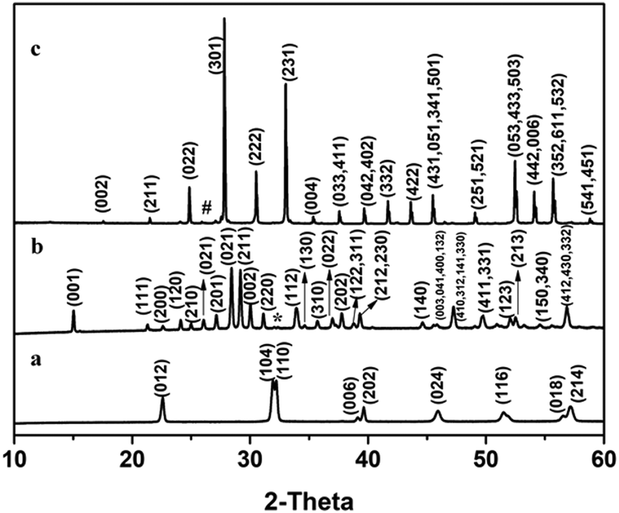 | ||
| Fig. 1 PXRD patterns of (a) BiFeO3, (b) Bi2Fe4O9 and (c) Bi25FeO40. * and # represents BiFeO3 and Bi2O3, respectively. | ||
The SEM images of BiFeO3, Bi2Fe4O9, and Bi25FeO40, respectively, are shown in Fig. 2a–c. For BiFeO3, we observed flower-like clusters formed from the assembly of cuboids (∼5–10 μm) (Fig. 2a). For Bi2Fe4O9 and Bi25FeO40, we observed square-shaped plates with a size of 2 μm (Fig. 2b) and cubes of ∼800 nm (Fig. 2c), respectively.
 | ||
| Fig. 2 SEM images of (a) BiFeO3, (b) Bi2Fe4O9, and (c) Bi25FeO40. | ||
From our previous study,11 it was observed that the electrochemical water oxidation activity, i.e., the performance of the Bi–Fe–O system towards the OER was highest for Bi2Fe4O9 followed by BiFeO3 and Bi25FeO40. This was indicated from the observed average current densities, which was found to follow the following trend:11 Bi2Fe4O9 > BiFeO3 > Bi25FeO40 while the overpotential (calculated at a current density of 1 mA cm−2; details of calculations are given in the ESI†) and charge transfer resistance were shown to follow the opposite trend: Bi25FeO40 > BiFeO3 > Bi2Fe4O9 (Fig. 3). The high performance of Bi2Fe4O9 towards the OER was then attributed to the plate-like morphology and the presence of Fe(oct)–O–Fe(td) linkages, probably resulting in covalency completion and creation of either Fe(oct)–O and Fe(td)– or Fe(td)–O and Fe(oct)-units facilitating adsorption of OH− ions.
 | ||
| Fig. 3 Plot showing the observed average current densities, overpotential, and charge transfer resistance of BiFeO3, Bi2Fe4O9, and Bi25FeO40. The values of the average current densities, overpotential, and charge transfer resistance were used from ref. 11. | ||
The water splitting reaction is dependent on the concentration of oxygen vacancies. The presence of oxygen vacancies can dictate the thermodynamic behavior of the material. The presence of these vacancies also leads to changes in the electronic behavior of the material. Both the electronic behavior and thermodynamic changes in the material affect the rate and efficiency of the catalysts for the water splitting reaction. Many reports in the literature support this fact. In one of our studies,24 we have also shown that oxygen vacancies present in oriented assemblies of SrTiO3 had a significant role in the HER. The presence of defect structures is a result of various factors. The key role in the formation of oxygen vacancies is based on the strength of the O–M bond, which in turn depends on the crystal structure of the material. Thus, to achieve a correlation between the structure and the properties, it is important to analyze the nature and relative concentration of the defects. To understand if defects have any major role in the OER behavior of Bi–Fe–O-based oxides, we carried out XPS, EPR, and PALS studies. Theoretical studies were carried out to understand the reason for different concentrations of defects, if any, in the three kinds of oxides.
The presence of oxygen vacancies in the three oxides was first analyzed using XPS studies (Fig. 4a–c). The peak corresponding to the metal–oxygen bond was observed in the high-resolution spectra of O 1s at 529.45, 529.6, and 529.45 eV for BiFeO3, Bi2Fe4O9, and Bi25FeO40, respectively. In addition to the metal–oxygen bond, peaks at 531.6, 531.1, and 531.5 eV were observed in the high-resolution spectra of O 1s for BiFeO3, Bi2Fe4O9, and Bi25FeO40. The peak centered at ∼531 eV corresponds to the presence of defects that are created due to oxygen vacancies in the oxide.24–28 Thus, analysis of the oxides using XPS confirmed the presence of defects arising due to oxygen vacancies. This observation led us to analyze further the oxides for the nature of the vacancies and their concentration.
 | ||
| Fig. 4 High resolution O 1s spectra of (a) BiFeO3, (b) Bi2Fe4O9, and (c) Bi25FeO40. | ||
In this regard, the first study we carried out was electron paramagnetic resonance (EPR), which is used for studying paramagnetic species, i.e., atoms, molecules, or ions that possess one or more unpaired electrons. Most defect sites show paramagnetic characteristics and thus can be identified by EPR spectra. Oxygen vacancies leave behind unpaired electrons that exhibit paramagnetic behavior. Typically, a peak at 2.001∼2.004 is attributed to natural surface oxygen vacancies, as reported in the literature.29 For the Bi–Fe–O system, EPR spectra (Fig. 5) were recorded for the three systems, BiFeO3, Bi2Fe4O9, and Bi25FeO40. In BiFeO3, bismuth and iron both exist in the +3 oxidation state, with the possible presence of oxygen vacancies. For BiFeO3, the g value was slightly higher than 2 (2.049), which may be due to the existence of the (Fe3+–OV) defect complex (OV, oxygen vacancy). In Bi2Fe4O9 and Bi25FeO40, the g value was observed at 2.029 and 2.061, respectively, also attributed to the oxygen vacancies. A peak at g = 1.69 is also observed in Bi25FeO40, possibly due to small iron oxide clusters, which were untraceable in XRD. The intensity of the EPR signal could be proportional to the concentration of oxygen vacancies in the material. Thus, the increased intensity in Bi2Fe4O9 followed by that in BiFeO3 and Bi25FeO40 can be interpreted by the presence of a higher concentration of oxygen vacancies in Bi2Fe4O9 and least in Bi25FeO40 (Fig. 5). This can possibly be from the fact that oxygen vacancies are likely to be formed at the surface with much ease in Bi2Fe4O9 due to its inherent crystal structure and bonding of the constituent atoms, i.e., the presence of Fe(Oct)–O–Fe(Td) linkages in Bi2Fe4O9. The trend in the intensity of the EPR signal, an indicator of the concentration of the oxygen vacancies present in the oxide, and the trend observed for the performance of the oxide as an electrocatalyst towards the OER correlate with each other. This suggests that the crystal structure and stoichiometry of the elements in the Bi–Fe–O system plays a significant role in the formation of oxygen vacancies, which govern the performance of the oxides towards the OER.
 | ||
| Fig. 5 EPR plot of BiFeO3, Bi2Fe4O9 and Bi25FeO40. | ||
To further understand the influence of the crystal structure on the formation of oxygen vacancies, theoretical studies using DFT calculations were performed. Table 1 reports the vacancy formation energies at the inequivalent sites of the three phases depicted in Fig. 6, both under O-poor and O-rich conditions, i.e., at the two experimental μO boundaries. The values of BiFeO3 are in line with those of previous investigations,30–35 confirming the validity of our computational setup. Formation energies of Bi2Fe4O9 vary across the oxygen sites. The energy required to form a vacancy is lowest at O4, requiring 0.92 and 3.77 eV under O-poor and O-rich conditions, respectively. We find that vacancies at O1 and O3 sites of Bi25FeO40 migrate towards O5, exhibiting negative formation energies, namely −0.89 and −0.45 eV under O-poor and O-rich conditions, respectively. The stoichiometry of the sillenite bismuth ferrite has been a matter of controversy. Some studies have reported the presence of one tetrahedral Bi5+ ion in the unit cell (in addition to 24 Bi3+ ions and one tetrahedral Fe3+ ion), resulting in a Bi25FeO40 formula.36,37 Other studies have instead suggested the presence of a tetrahedral Bi3+ ion with an oxygen vacancy at one of its vertices, i.e. a Bi25FeO39 composition.38,39 While our Bi25FeO40 model with cations not randomly distributed at the tetrahedral sites suggests a cautious interpretation of the results, the negative formation energy at O5 lends strong support to a Bi25FeO39 formula with an oxygen vacancy in each tetrahedron. Unfortunately, however, a reliable model of Bi25FeO39 would require randomising also the oxygen vacancies, in addition to the tetrahedral Bi3+ and Fe3+ ions, in a prohibitively large supercell.40 For this reason, we have not pursued the computational investigation of Bi25FeO39 further.
| Sample | Site | Formation energy (eV) | |
|---|---|---|---|
| O-poor | O-rich | ||
| BiFeO3 | O1 | 1.94 | 3.96 |
| Bi2Fe4O9 | O1 | 1.51 | 4.36 |
| O2 | 1.38 | 4.23 | |
| O3 | 1.71 | 4.56 | |
| O4 | 0.92 | 3.77 | |
| Bi25FeO40 | O1 | Unstable | Unstable |
| O2 | 0.82 | 1.26 | |
| O3 | Unstable | Unstable | |
| O4 | 0.49 | 0.93 | |
| O5 | −0.89 | −0.45 | |
| O6 | 0.48 | 0.92 | |
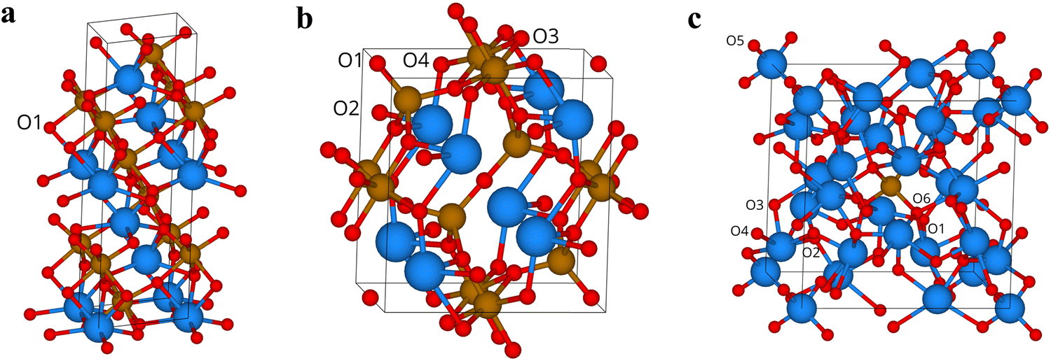 | ||
| Fig. 6 The three bismuth ferrite phases investigated were (a) BiFeO3, (b) Bi2Fe4O9, and (c) Bi25FeO40. Inequivalent oxygen sites are labelled. | ||
To better interpret the difference in vacancy formation energies between BiFeO3 and Bi2Fe4O9, the concentration of oxygen vacancies under the two extreme oxygen conditions is shown in Fig. 7. Our results show that the amount of oxygen vacancies present in Bi2Fe4O9 is much larger than that in BiFeO3, with a difference that can be up to a few orders of magnitude under O-poor conditions. Thus, the formation of a large number of oxygen vacancies owing to lower formation energy for Bi2Fe4O9 explains the trend observed for the intensity of the EPR signal arising due to the presence of oxygen vacancies, as discussed in the previous section.
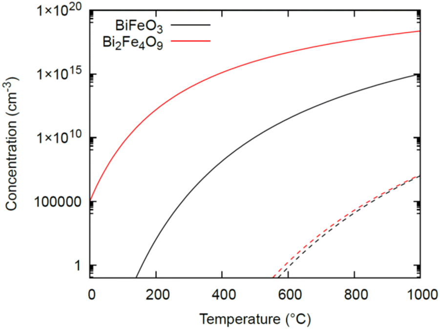 | ||
| Fig. 7 Concentration of oxygen vacancies in BiFeO3 and Bi2Fe4O9 as a function of temperature under both O-poor (solid lines) and O-rich (dashed lines) conditions. | ||
To further understand the type of oxygen vacancies present in the three kinds of oxides in the Bi–Fe–O system, PALS studies were carried out. Positrons on striking the sample can get trapped in it. It may then be localized at neutral and negative vacancies due to the missing positive ion core. These results showing observable changes in the positron lifetime can be used to probe defects/voids/free volume at the sub-nm scale in a material. The annihilation data are used to obtain the concentration of the vacancies. They can also be used to obtain information about the type of vacancies and their chemical environment. The positron lifetimes are fitted using the following equation (eqn (3)):
 | (3) |
| λi = τ−1i | (4) |
 | ||
| Fig. 8 Positron annihilation lifetime spectra for the Bi–Fe–O system. | ||
| Sample | τ 1 (ps) | I 1 (%) | τ 2 (ps) | I 2 (%) | τ ave (ps) |
|---|---|---|---|---|---|
| BiFeO3 | 212 ± 5 | 74 ± 1 | 323 ± 16 | 26 ± 1 | 241 ± 7 |
| Bi2Fe4O9 | 258 ± 2 | 89 ± 2 | 470 ± 20 | 11 ± 2 | 282 ± 10 |
| Bi25FeO40 | 223 ± 4 | 19 ± 1 | 390 ± 2 | 81 ± 1 | 358 ± 4 |
Correlating the information from PALS studies and the trend observed during the OER with the Bi–Fe–O system as an electrocatalyst, it can be concluded that the presence of monovacancies enhances the catalytic behavior of the oxides. The electrocatalytic activity of a material is affected by the presence of active sites and their accessibility. It has been known45 that when vacancies are present in the system, they introduce local modifications in the binding energies of the atoms, thus affecting the activity. For the oxygen evolution reaction in an alkaline medium, the mechanism of the OER is very well established in the literature,46 wherein the adsorption of OH− on the surface of the material occurs to form M–OOH intermediates, which further evolves O2. The adsorption of OH− is increased when vacancy sites are present, which leads to higher activity in the OER. In this study, the concentration of the monovacancies, as observed from the I1 of the PALS study, was found to follow the trend: Bi2Fe4O9 > BiFeO3 > Bi25FeO40, which correlated with the trend of the three oxides observed towards the electrochemical OER. We presume that the increased concentration of the monovacancies with the order Bi2Fe4O9 > BiFeO3 > Bi25FeO40 is likely to affect the cumulative adsorption of OH− ions, which affected the OER activity. However, the atomic-level mechanism behind the increased performance remains unknown. Future computational investigations comparing the OER energy diagrams of Bi2Fe4O9 and other oxides with and without monovacancies can provide important insights. Monovacancies and defect clusters present in a system are influenced by the crystal structure of the system. The oxygen vacancies created in a structure are dependent on the surrounding atoms, bond strengths, and stability of the system.
Monovacancies formed in the system are easily accessible sites as they are generally surface defects, whereas the defect clusters formed are deeply trapped.47,48 For this reason, there is the possibility that the efficiency of these clusters towards participating in the OER is lower than that of the systems with monovacancies. A schematic representation of the OER in the presence of monovacancies and defect clusters is showcased in Fig. 9 for better clarity. The open-circuit voltage (OCV) measured for our system is BiFeO3: 1.207 V, Bi2Fe4O9: 1.208 V and Bi25FeO40: 1.349 V. The stability studies of BiFeO3, Bi2Fe4O9, and Bi25FeO40 were carried out at 1.7 V vs. RHE for BiFeO3 and Bi25FeO40, while at 1.8 V vs. RHE for Bi2Fe4O9. Under alkaline conditions, the catalysts were found to be stable for 10 hours under continuous measurements (Fig. S2a–c, ESI†). Thus, overall, it was reflected from the study that the nature and relative concentration of oxygen vacancies were greatly influenced by the crystal structure and the stoichiometry of the elements in the Bi–Fe–O system, which influenced the OER carried out with these systems. PALS studies reflected that monovacancies within the system have a greater influence on the OER than the defect clusters.
 | ||
| Fig. 9 Schematic diagram showcasing the OER in the presence of (a) only monovacancies (using Bi2Fe4O9 as the represented structure; color representation: red: Fe; green: Bi; blue: O; yellow: H; white: O vacancies) and (b) defect clusters (one defect cluster encircled) along with monovacancies (using Bi25FeO40 as the represented structure consisting of 1 unit cell along ‘a’, 3 unit cell along ‘b’, 2 unit cell along ‘c’; color representation: green: Bi, corner and body center of each unit cell has a partial occupancy of Fe along with Bi, blue: O, yellow: H, and white: O vacancies). | ||
Conclusions
The electrocatalytic behavior of three distinct Bi–Fe–O systems—namely, BiFeO3, Bi2Fe4O9, and Bi25FeO40—exhibited notable variations attributed to different crystal structures within each system. Thus, defect studies via XPS, EPR, and PALS were carried out to understand the underlying mechanism of their behaviors for the electrochemical OER based on the crystal structures. The XPS and EPR studies confirmed the presence of oxygen vacancies in all three systems, from the characteristic peak at ∼531 eV in XPS and the g value for oxygen vacancies of around 2.029 in EPR. The intensities in EPR indicated a concentration of oxygen vacancies, which was the highest for Bi2Fe4O9, followed by BiFeO3 and Bi25FeO40, which correlated well with the observed trend of the OER with these oxides. Theoretical studies also supported the conclusion from the XPS and EPR by showcasing the low energy of formation energy and high concentration of oxygen vacancies in Bi2Fe4O9. Furthermore, PALS studies indicated the presence of the majority of oxygen monovacancies in BiFeO3 and Bi2Fe4O9 and defect clusters in Bi25FeO40. The study carried out showcased that the nature and relative concentration of oxygen vacancies were greatly influenced by the crystal structure and the stoichiometry of the elements in the Bi–Fe–O system. This had a major influence on the OER carried out with these systems. Thus, the study carried out was an effort to understand the electrochemical behaviour of the three oxides in the Bi–Fe–O system from the perspective of the presence of oxygen vacancies. However, more advanced in situ experimental techniques in conjunction with EPR, XPS, etc., could help in understanding the effect of vacancies on electrochemical behaviour under real conditions of electrocatalysis.Conflicts of interest
There are no conflicts of interest.Acknowledgements
SJ and AV thank INST for the fellowship. SV thanks CSIR (01(2943)/18-EMR-II), Govt. of India, for funding. Via UT's membership of the UK's HEC Materials Chemistry Consortium funded by EPSRC (EP/R029431, EP/X035859/1), this work used the ARCHER2 UK National Supercomputing Service (https://www.archer2.ac.uk).References
- A. Eckmann, A. Felten, A. Mishchenko, L. Britnell, R. Krupke, K. S. Novoselov and C. Casiraghi, Nano Lett., 2012, 12, 3925 CrossRef CAS PubMed.
- L. Vicarelli, S. J. Heerema, C. Dekker and H. W. Zandbergen, ACS Nano, 2015, 9, 3428 CrossRef CAS PubMed.
- F. Yan, K. Huang, T. Jiang, X. Zhou, Y. Shi, G. Ge, B. Shen and J. Zhai, Energy Storage Mater., 2020, 30, 392 CrossRef.
- Y. Yan, Z. Li, L. Jin, H. Du, M. Zhang, D. Zhang and Y. Hao, ACS Appl. Mater. Interfaces, 2021, 13, 38517 CrossRef CAS PubMed.
- H. Liu, W. Lei, Z. Tong, X. Li, Z. Wu, Q. Jia, S. Zhang and H. Zhang, Adv. Mater. Interfaces, 2020, 7, 2000494 CrossRef CAS.
- M. V. Ganduglia-Pirovano, A. Hofmann and J. Sauer, Surf. Sci. Rep., 2007, 62, 219 CrossRef CAS.
- C.-Z. Yuan, S. Huang, H. Zhao, J. Li, L. Zhang, Y. Weng, T.-Y. Cheang, H. Yin, X. Zhang and S. Ye, Energy Adv., 2023, 2, 73 RSC.
- Z. Cai, Y. Bi, E. Hu, W. Liu, N. Dwarica, Y. Tian, X. Li, Y. Kuang, Y. Li, X.-Q. Yang, H. Wang and X. Sun, Adv. Energy Mater., 2018, 8, 1701694 CrossRef.
- B. Liu, Y. Wang, H.-Q. Peng, R. Yang, Z. Jiang, X. Zhou, C.-S. Lee, H. Zhao and W. Zhang, Adv. Mater., 2018, 30, 1803144 CrossRef PubMed.
- P. Zhou, Y. Wang, C. Xie, C. Chen, H. Liu, R. Chen, J. Huo and S. Wang, Chem. Commun., 2017, 53, 11778 RSC.
- A. Vijay, K. V. Ramanujachary, S. E. Lofland and S. Vaidya, Electrochim. Acta, 2022, 407, 139887 CrossRef CAS.
- J. V. Olsen, P. Kirkegaard, N. J. Pedersen and M. Eldrup, Phys. Status Solidi C, 2007, 4, 4004 CrossRef CAS.
- E. Heifets, E. A. Kotomin, A. A. Bagaturyants and J. Maier, J. Phys. Chem. Lett., 2015, 6, 2847 CrossRef CAS PubMed.
- T. D. Kühne, M. Iannuzzi, M. D. Ben, V. V. Rybkin, P. Seewald, F. Stein, T. Laino, R. Z. Khaliullin, O. Schütt, F. Schiffmann, D. Golze, J. Wilhelm, S. Chulkov, M. H. Bani-Hashemian, V. Weber, U. Borštnik, M. Taillefumier, A. S. Jakobovits, A. Lazzaro, H. Pabst, T. Müller, R. Schade, M. Guidon, S. Andermatt, N. Holmberg, G. K. Schenter, A. Hehn, A. Bussy, F. Belleflamme, G. Tabacchi, A. Glöβ, M. Lass, I. Bethune, C. J. Mundy, C. Plessl, M. Watkins, J. VandeVondele, M. Krack and J. Hutter, J. Chem. Phys., 2020, 152, 194103 CrossRef PubMed.
- S. Goedecker, M. Teter and J. Hutter, Phys. Rev. B: Condens. Matter Mater. Phys., 1996, 54, 1703 CrossRef CAS PubMed.
- J. P. Perdew, K. Burke and M. Ernzerhof, Phys. Rev. Lett., 1996, 77, 3865 CrossRef CAS PubMed.
- J. VandeVondele and J. Hutter, J. Chem. Phys., 2007, 127, 114105 CrossRef PubMed.
- R. H. Byrd, P. Lu, J. Nocedal and C. Zhu, SIAM J. Sci. Comput., 1995, 16, 1190 CrossRef.
- C. Adamo and V. Barone, J. Chem. Phys., 1999, 110, 6158 CrossRef CAS.
- M. Guidon, J. Hutter and J. VandeVondele, J. Chem. Theory Comput., 2010, 6, 2348 CrossRef CAS PubMed.
- P. Erhart and K. Albe, J. Appl. Phys., 2008, 104, 044315 CrossRef.
- P. Hermet, M. Goffinet, J. Kreisel and P. Ghosez, Phys. Rev. B: Condens. Matter Mater. Phys., 2007, 75, 220102 CrossRef.
- S. Phapale, R. Mishra and D. Das, J. Nucl. Mater., 2008, 373, 137 CrossRef CAS.
- A. Vijay, S. Priya S, U. Terranova, M. Maity and S. Vaidya, ChemNanoMat, 2022, 8, e202200283 CrossRef CAS.
- S. Kumar and C. Rath, Phys. Status Solidi A, 2020, 217, 1900756 CrossRef CAS.
- W. Cao, O. K. Tan, J. S. Pan, W. Zhu and C. V. Gopal Reddy, Mater. Chem. Phys., 2002, 75, 67 CrossRef CAS.
- J. Bao, X. Zhang, B. Fan, J. Zhang, M. Zhou, W. Yang, X. Hu, H. Wang, B. Pan and Y. Xie, Angew. Chem., Int. Ed., 2015, 54, 7399 CrossRef CAS PubMed.
- Y. Tian and F. Xue, J. Mater. Sci.: Mater. Electron., 2019, 30, 15452 CrossRef CAS.
- Y. Zhang, Z. Chen and Z. Lu, Nanomater, 2018, 8, 261 CrossRef PubMed.
- S. J. Clark and J. Robertson, Appl. Phys. Lett., 2009, 94, 022902 CrossRef.
- G. Geneste, C. Paillard and B. Dkhil, Phys. Rev. B, 2019, 99, 024104 CrossRef CAS.
- T. R. Paudel, S. S. Jaswal and E. Y. Tsymbal, Phys. Rev. B: Condens. Matter Mater. Phys., 2012, 85, 104409 CrossRef.
- T. Shimada, T. Matsui, T. Xu, K. Arisue, Y. Zhang, J. Wang and T. Kitamura, Phys. Rev. B, 2016, 93, 174107 CrossRef.
- Q. Xu, M. Sobhan, Q. Yang, F. Anariba, K. Phuong Ong and P. Wu, Dalton Trans., 2014, 43, 10787 RSC.
- Z. Zhang, P. Wu, L. Chen and J. Wang, Appl. Phys. Lett., 2010, 96, 012905 CrossRef.
- D. C. Craig and N. C. Stephenson, J. Solid State Chem., 1975, 15, 1 CrossRef CAS.
- A. Ramanan and J. Gopalakrishnan, Indian J. Chem., 1985, 24A, 594 CAS.
- S. F. Radaev, L. A. Muradyan and V. I. Simonov, Acta Crystallogr., Sect. B: Struct. Sci., 1991, 47, 1 CrossRef.
- M. Valant and D. Suvorov, Chem. Mater., 2002, 14, 3471 CrossRef CAS.
- C. A. Scurti, N. Auvray, M. W. Lufaso, S. Takeda, H. Kohno and D. J. Arenas, AIP Adv., 2014, 4, 087125 CrossRef.
- D. Lozano-Castello, D. Cazorla-Amorós, A. Linares-Solano, P. Hall and J. Fernández, Stud. Surf. Sci. Catal., 2000, 128, 523 CrossRef CAS.
- H. Schneider, J. Schreuer and B. Hildmann, J. Eur. Ceram. Soc., 2008, 28, 329 CrossRef CAS.
- H. Dai, F. Ye, Z. Chen, T. Li and D. Liu, J. Alloys Compd., 2018, 734, 60 CrossRef CAS.
- A. Mukherjee, M. Banerjee, S. Basu, P. M. G. Nambissan and M. Pal, J. Phys. D: Appl. Phys., 2013, 46, 495309 CrossRef.
- L. Fu, S. Zhou, M. Xiang, J. Yang, W. Fan, Z. Yang and J. Ou, J. Electroanal. Chem., 2022, 921, 116650 CrossRef CAS.
- K. Zhang and R. Zou, Small, 2021, 17, 2100129 CrossRef CAS PubMed.
- Z.-P. Li, T. Mori, J. Zou and J. Drennan, Mater. Res. Bull., 2013, 48, 807 CrossRef CAS.
- J. A. Kilner, Chem. Lett., 2008, 37, 1012 CrossRef CAS.
Footnote |
| † Electronic supplementary information (ESI) available: Calculation of overpotential; measurement of open circuit voltage (OCV); stability phase diagram of bismuth ferrite; stability studies of the three oxides during the electrocatalytic OER; oxygen chemical potentials in the three bismuth ferrite phases. See DOI: https://doi.org/10.1039/d4cp00348a |
| This journal is © the Owner Societies 2024 |