
 Open Access Article
 This Open Access Article is licensed under a Creative Commons Attribution-Non Commercial 3.0 Unported Licence
Eu(III)-doped calcium molybdate nano- and microstructures: microfluidic synthesis and morphology tuning via solvent dielectric constant and viscosity control†
Pietro
Ostellari
 a,
Francesca
Tajoli
a,
Ilaria
Fortunati
a,
Tommaso
Carofiglio
a,
Denis
Badocco
a,
Paolo
Pastore
a and
Silvia
Gross
*ab
a,
Francesca
Tajoli
a,
Ilaria
Fortunati
a,
Tommaso
Carofiglio
a,
Denis
Badocco
a,
Paolo
Pastore
a and
Silvia
Gross
*ab
aDepartment of Chemical Sciences, University of Padova, Via Francesco Marzolo 1, 35131, Padova, Italy. E-mail: silvia.gross@unipd.it
bInstitute for Chemical Technology and Polymer Chemistry (ITCP) – Karlsruhe Institute of Technology (KIT), Karlsruhe, Germany
First published on 25th September 2024
Abstract
A novel and green microfluidic approach was employed for the synthesis of undoped and Eu(III)-doped calcium molybdate at room and low temperatures. The controlled formation of nano- and microstructures was successfully achieved by tuning the nucleation and growth stages of particle formation through a systematic variation of the viscosity and dielectric constant of the reaction medium, i.e. water and ethanol in different weight ratios and at different temperatures. Thanks to the inherent advantages of the microfluidic approach in terms of mass transport, mixing and heat exchange, it was possible to carry out the reaction at low temperature (−4 °C) in an effective manner and to further control the reaction conditions to achieve the formation of small and monodisperse nanoparticles. The synthesised nano- and microstructures, displaying different morphologies depending on reaction conditions, were investigated from a structural (XRD), dimensional and morphological (TEM, SEM), compositional (ICP-MS), and functional (photoluminescence) point of view. The remarkable photoluminescence properties of pure and Eu(III)-doped calcium molybdate structures proved that they are promising materials to be employed as phosphors.
Introduction
Calcium molybdate (CM), CaMoO4, is a functional ternary oxide that has been widely used for its intrinsic photoluminescence properties.1–5 CM finds application as phosphor (also for fingerprint detection6), as a material for solid-state lasers, white-light LEDs (WLEDs), and as a scintillator.7–10 It is particularly suitable as a host matrix for dopant ions such as rare earth ions, which extend the fields of application of this material.11,12Calcium molybdate occurs naturally in the mineral powellite, which belongs to the scheelite family (CaWO4), together with other minerals with the general formula ABO4 (A = Ca, Sr, Ba, Pb; B = Mo, W).13 The scheelite crystalline structure is tetragonal body-centered (schematic representation of the unit cell in Fig. 1), whose spatial group is I41/a (no. 88) and point symmetry C64h.13,14 In detail, the crystalline structure is made up of [CaO8] polyhedra, each one sharing corners with eight adjacent [MoO4] tetrahedra.5,15–18 As previously stated, CaMoO4 is an interesting host matrix for the production of Ln-based phosphor materials, as is widely described in the literature.19,20 Dopant lanthanide ions such as Eu3+, Tb3+, Yb3+, and Dy3+ were found to replace Ca2+ ions in scheelite's crystalline lattice19 thanks to their comparable ionic radius (i.e. 1.12 Å and 1.066 Å for Ca2+ and Eu3+ in VIII coordination, respectively21). The [MoO4]2− unit of the matrix in Ln-doped calcium molybdate can absorb UV light with a large cross section and excite the doping lanthanide ion via an energy transfer mechanism, resulting in narrow spectrum emission lines due to lanthanide f–f electronic transitions.19,22
 | ||
| Fig. 1 Crystalline structure of calcium molybdate; Ca, Mo and O atoms are represented in blue, purple, and red, respectively. | ||
In recent years, a variety of methods has been proposed for the synthesis of undoped and Eu-doped CM, such as hydrothermal process,23–25 microwave-assisted synthesis,26,27 pulsed laser-ablation,28 co-precipitation,8,29,30 hot injection route,9,31 microemulsion approach,3,32 and more recently also a miniemulsion approach by our group.20 In general, the co-precipitation process between Ca2+ and MoO42− was performed in aqueous solution or mixed solvents (e.g. alcohol and water) and possibly heated under varied conditions, with remarkable shape control over the final particle aggregation into mesostructures, obtained by varying the reaction parameters like solvent composition, reagent concentration or time.27,32,33 However, to date, no studies addressing the synthesis of undoped and Eu-doped calcium molybdate in continuous-flow microreactors were reported.
In recent years, the microfluidic approach became very attractive for the synthesis of inorganic nanoparticles, thanks to the unique properties of microfluidic reactors34–38 (i.e. continuous-flow reactors with micrometric channels, ensuring flow regimes characterised by laminar flow and Reynolds number lower than 250).37,39 In particular, microfluidic reactors allow (i) a very fast mixing of reaction mixtures on the order of milliseconds39–41 and (ii) an excellent heat transfer from and to the reaction mixtures thanks to the high surface-to-volume ratio of channels.37 Thanks to these features, in microfluidic devices a highly homogeneous reaction mixture is ensured, avoiding gradients in reactants' concentration and temperature, and a fine control on size, size distribution and composition of the final product can be pursued.36 Indeed, the superior homogeneity of the reaction environment allows to prevent random (both timely and spatially) nucleation bursts and uncontrolled growth by agglomeration in the microfluidic reactor, and it has been successfully exploited for the synthesis of inorganic nanostructures with exceptional synthetic control on the products' final features.38,42–44 On the other hand, more simple mixing systems, such as batch syntheses, are typically characterised by non-homogeneous chemical environments and concentration gradients, usually leading to uncontrolled reaction outcome. The need for a more advanced synthetic approach for the controlled synthesis of functional systems such as calcium molybdate was demonstrated also in a previous work by Mazzariol et al.,20 in which we compared two synthetic methods for CM preparation, i.e. inverse miniemulsion synthesis versus traditional batch synthesis, and we highlighted the lack of control on reaction outcomes in the batch samples, leading to broader size distribution and scarce optical properties of the materials.
Herein, we report an innovative and unprecedented approach for the synthesis of undoped and Eu(III)-doped calcium molybdate particles via a simple, green, ambient and low temperature microfluidic approach based on the controlled precipitation of CaMoO4. In particular, the raw materials employed, solvents, temperature conditions, and the inherent safe conditions ensured by the microfluidics setup (vide infra for more detailed information) are all compliant with the Green Chemistry principles published by Anastas and Warner.45
Moreover, by exploiting the peculiarities of microfluidics, we performed a systematic exploration of the parameters landscape, such as solvent mixture composition, quenching method and temperature, to precisely control and tune calcium molybdate features in terms of particle and crystallite size, primary particle aggregation in differently shaped microparticles, and optical properties.
Materials and methods
Chemicals
Sodium molybdate dihydrate (Na2MoO4·2H2O) was purchased from Alfa-Aesar. Calcium nitrate tetrahydrate (Ca(NO3)2·4H2O) and ethanol (reagent grade >99.9%) were purchased from Carlo Erba (Milano, Italy). Europium(III) nitrate pentahydrate (Eu(NO3)3·5H2O) was purchased from Merck KGaA. All chemicals were used without further purification.Microfluidic setup
For the syntheses of undoped and Eu(III)-doped calcium molybdate samples, two microfluidic setups were employed (see Fig. 2). The first setup was built using two syringe pumps (New Era Pump Systems, Inc.), 0.8 mm diameter PTFE tubes of different lengths and a T-shaped PEEK micromixer (Fig. 2a). Molybdate and calcium precursor solutions (molar ratio of 1![[thin space (1/6-em)]](https://www.rsc.org/images/entities/char_2009.gif) :1) were pumped separately into the reactor with a flow rate of 1.2 mL min−1, and the reagent streams met at 180°. The reaction mixture was quenched by dilution at the end of the reactor in a collecting vessel after a residence time RT (i.e. time of residence of the product in the microfluidic reactor, from the micromixer to the collecting beaker, defined as the ratio between volume of channels – proportional to their length for cylindrical tubes – and total flow rate).47,48
:1) were pumped separately into the reactor with a flow rate of 1.2 mL min−1, and the reagent streams met at 180°. The reaction mixture was quenched by dilution at the end of the reactor in a collecting vessel after a residence time RT (i.e. time of residence of the product in the microfluidic reactor, from the micromixer to the collecting beaker, defined as the ratio between volume of channels – proportional to their length for cylindrical tubes – and total flow rate).47,48
 | ||
| Fig. 2 Schematic representation of the (a) first and (b) second microfluidic setup. The dashed line indicates the portion of the setup immersed in a cold bath at −4 °C. | ||
The first setup was modified to obtain the second setup, adding a third syringe pump and a second T-shaped micromixer, to perform in-line the quenching of the reaction (Fig. 2b). The reaction and quencher streams met at 180° with the same flow rate, ensuring a dilution of 1:1 (v/v) of the reaction, and the product was collected after 1 s of residence time.
For the Eu(III)-doped samples, a stoichiometric amount of Eu(III) precursor (Eu(NO3)3) was added to the calcium precursor in order to obtain the desired dopant atomic percentage (i.e. 3 at%, calculated as molEu/molMo), resulting in a pH of 4.
For all syntheses, the slurry obtained after the quenching step was repeatedly centrifuged (15000 rpm, 5 min) and washed with acetone. The obtained powder was dried overnight in a vacuum desiccator at room temperature.
(i) Solvent mixture composition: metal precursor solutions were prepared in Milli-Q water/ethanol mixtures, screening the relative amount of ethanol from 20 to 50 wt%.
(ii) Quenching method: the quenching of the reaction mixture was performed by dilution either in an excess of Milli-Q water/ethanol mixture (same wt% of ethanol as the precursor solutions) or in pure ethanol. Depending on the microfluidic setup employed, the quenching was carried out into a collection vessel at the end of the reactor (first setup) or in flow (second setup). The quencher volume was equal to the sum of the volumes of precursor solutions pumped throughout the entire synthesis.
(iii) Temperature: the syntheses of undoped and Eu(III)-doped CaMoO4 were carried out at ambient temperature (about 20 °C) and at −4 °C. In order to carry out the reaction at low temperature (−4 °C), the first setup (tubing, micromixer and collecting vessel) was immersed into a NaCl/ice cold bath (3.5 wt% NaCl to achieve the temperature of −4 °C).
X-ray powder diffraction (XRPD)
The XRPD patterns of the undoped and Eu(III)-doped CaMoO4 samples (as ground powder) were collected with a Bruker AXS D8 Advance Plus instrument equipped with a LYNEXEYE detector in 1D mode, by using Cu Kα1,2 radiation (λ1 = 1.54060 Å; λ2 = 1.54439 Å, with relative intensity Kα2/Kα1 = 0.5). Diffractograms were recorded in a Bragg–Brentano geometry in the 10–80° 2θ range, with 0.014° 2θ scan step and 0.3 s per step acquisition time. The crystalline phase was identified through the search and match procedure of Bruker Diffrac.EVA software. The collected XRD patterns were fitted using the Pawley method for the estimation of lattice parameters and crystallite size.49 This method was implemented using TOPAS software (version 6, Bruker AXS, Germany). The fitting procedure started by defining the phase and space group of calcium molybdate obtained from Diffrac.EVA. Subsequently a background correction was applied, involving a polynomial function to correct the noise in the pattern. The order of the polynomial was chosen based on the complexity of the background. A sample displacement correction was applied in order to correct peak position. The reflections were fitted with a pseudo-Voigt function, and lattice parameters, crystallite size and strain have been iteratively refined. The quality of the fitting was assessed by the Rwp parameter, which was lower than 10% for all patterns. The error associated to the crystallite sizes was calculated by the software in the range between 0.1 and 0.9 nm.Transmission electron microscopy (TEM)
TEM micrographs were collected with a FEI Tecnai G microscope operating at 100 kV, equipped with Olympus Veleta and TVIPS F114 cameras. Samples were prepared by suspending the dried powders in ethanol through sonication and then depositing them on 300 mesh lacey carbon-coated copper grids. Some of the particles were manually segmented and measured using the ImageJ package.50Scanning electron microscopy (SEM)
SEM micrographs were collected with a Zeiss SUPRA 40VP microscope equipped with an Oxford INCA X-Sight X-ray detector, with a 5.0 kV acceleration of the primary beam and detecting secondary electrons. Samples were prepared by dispersing the dried powders in ethanol through tip sonication (Sartorius Stedim LABSONIC P, 30 s, 0.9 s pulse, 100 W power) and then depositing them on a Si fragment fixed to the specimen stub with a carbon tape.Photoluminescence and optical properties
The diffuse reflectance spectrum of powder samples in the range 250–800 nm was measured with an FLS1000 spectrometer equipped with a BaSO4-coated integrating sphere, a Xe lamp as excitation source and a R13456 photomultiplier as detector. A BaSO4 plug was used as reference for the calculation of the diffuse reflectance spectra. The excitation and emission slits were set to 2.5 and 0.14 nm, respectively.The absorption spectra F(R) was calculated from reflection spectra employing the Kubelka–Munk function:

Excitation and emission spectra were recorded on an FLS1000 spectrometer (Edinburgh Instruments, UK) equipped with double excitation and emission monochromators, a 450 W Xe lamp and an air-cooled single-photon counting photomultiplier (Hamamatsu R13456). For steady-state emission detection in the range 400–750 nm, the excitation wavelength was fixed at 285 nm. The excitation spectra recorded in the region 250–500 nm were measured by monitoring the emission signal at 612 nm.
Time-resolved lifetime measurements were acquired on the same FLS1000 spectrometer using a Xe μ-second flash lamp (285 nm and 100 Hz frequency) as excitation source. Luminescence decays were recorded using the multi-channel scaling (MCS) technique in the range 0–10 ms, and they were analyzed with the Fluoracle software using a two-component equation.
Quantum yields (QYs) were calculated by measuring the emission spectrum of the phosphor powder in the BaSO4-coated integration sphere mounted in the FLS1000 instrument. A BaSO4 plug was used for the measurement of the reference spectrum. The excitation wavelength was fixed at 285 nm.
All measurements were conducted at room temperature.
Inductively coupled plasma-mass spectrometry (ICP-MS)
:3 HNO3:HCl weight mixture diluted to 5 wt% with Milli-Q water. The parameters of the calibration lines were obtained by using the Theil-Sen non-parametric regression technique using Ge as internal standard (TraceCERT, Sigma-Aldrich lot: BCBR4340V).52
:3 HNO3:HCl weight mixture at 120 °C for 2 h. The samples were suitably diluted, and the internal standard (Ge 50 ppb) was added consistently to the calibration standards. The protocol was verified by spiking Eu and Mo, resulting in 95% and 98% recovery, respectively.
Results and discussion
The design of the experimental setup for the microfluidic synthesis of pure and Eu(III)-doped calcium molybdate and the screening of the explored synthetic parameters were rationally based on the acknowledged fundamental theories of nanoparticle formation and colloid stability as well as on the peculiarities of continuous-flow methods. In particular, the formation and growth of particles can be rationalised according to LaMer and Dinegar's model of homogeneous nucleation,53,54 encompassing three stages: (i) the solute supersaturation condition is reached, (ii) the first nuclei are formed, (iii) the solute's concentration decreases and the supersaturation is relaxed but still remains high enough to enable nuclei growth. Afterwards, the overall free energy of the system can be reduced by aggregation of the primary particles, if not properly stabilised, into secondary structures.54 The unique conditions of a microfluidic reactor (i.e. the efficient and fast mixing and the flowing and dynamic nature of the system) enable the achievement of (i) a highly homogeneous chemical environment in terms of solute concentration and temperature and (ii) a temporal (and consequently spatial) separation of the NP nucleation and growth stages. Thanks to these, timely and spatially random nucleation bursts and uncontrolled agglomeration can be avoided under microfluidic conditions. The introduction of a quenching step (either a concentration or a thermal quenching, i.e. by dilution or by suddenly cooling the reaction mixture, respectively) before the stage of particle aggregation could be valuable in minimizing the nanoparticle aggregation and thus in obtaining monodisperse nanoparticles.55 In the work herein reported, the quenching step was performed by dilution of the reaction mixture, with the aim of decreasing the solute concentration under the supersaturation limit, preventing any further nucleation events and at the same time slowing down the rate of particle aggregation.Generally, the aggregation of the primary particles can be strongly influenced by varying the viscosity and the dielectric constant of the medium. In particular, according to the Stokes–Einstein relation,56 the diffusion coefficient and the viscosity are inversely proportional, and thus a variation of viscosity of the reaction medium affects the mass transfer in solution, as well as the fluid dynamics and mixing in continuous-flow approaches. Moreover, according to the DLVO theory,57 the dielectric constant is one of the parameters influencing the stabilisation of electric charges on the particle's surface, which are responsible for the electrostatic stabilisation of colloids. Finally, charges on the particle's surface are responsible for the relative orientation of particles, thus in turn affecting particle aggregation.22
Since calcium molybdate is not fully insoluble in water (Ksp = 1.46 × 10⁻⁸),58 to ensure that the reaction was occurring exclusively into the flow reactor and ended into the collecting beaker, its solubility was lowered by adding a non-solvent (i.e. ethanol). Indeed, according to a paper by Jouyban et al.,59 by adding ethanol to water, the viscosity of the mixture increases to reach a maximum at about 50 wt% ethanol (see Fig. S1†), and, by increasing the ethanol content from 20 to 50 wt%, the solvent's viscosity increases from 1.8 to 2.5 mPa s. As a result, when performing the reaction in solvent mixtures with higher ethanol wt%, crystallites growth and particle aggregation should be limited. Moreover, through the relationship proposed by Soltanpour et al.,60 it was possible to determine that the solvent dielectric constant linearly decreases by increasing the ethanol content (see Fig. S2†). It is noteworthy that another way to tune the viscosity and the dielectric constant of the reaction mixture is a variation of the reaction temperature. Indeed, as extensively reported in the ESI,† by lowering the temperature, both the viscosity and the dielectric constant of the water/ethanol mixtures increase.
Taking into account these considerations, the microfluidic synthesis of undoped and Eu(III)-doped calcium molybdate was addressed by rationally exploring the experimental parameters' landscape to evaluate their role, and ultimately the role of variations of the viscosity and dielectric constant of the reaction medium, in determining the reaction outcome. In particular, the effects of (i) solvent mixture composition, (ii) quenching method, and (iii) temperature on the size and aggregation of the synthesised primary particles were systematically investigated.
The tight space–time correlation that is ensured under microfluidic conditions enables the fine-tuning of the residence time, i.e. the reaction time, by varying either the tubing length or the flow rate. For this purpose, a first optimisation of the microfluidic setup for the synthesis of CM was carried out by testing different tubing lengths, i.e. screening the residence time and reagent concentrations, until opalescent droplets continuously coming out of the setup were obtained. In such a way, it was ensured that the reaction occurs within the constrained environment of the microfluidic setup, characterised by controlled fluid dynamics and high homogeneity (absence of thermal and compositional gradients).
Effect of reaction parameters
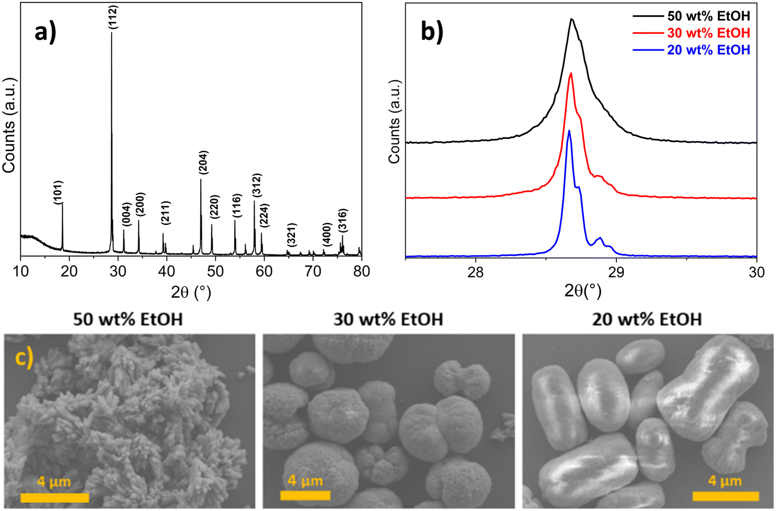 | ||
| Fig. 3 (a) XRD pattern of undoped calcium molybdate. Miller indices for the scheelite-type structure are reported. Comparison of (b) broadening of (112) XRD reflections and (c) SEM micrographs of calcium molybdate synthesised with different wt% of ethanol in reaction solvent and quenching in solvent mixture (first setup). | ||
In addition to having a remarkable effect on the crystallite size of CM, the ethanol content of the employed reaction medium was observed to play a relevant role also in influencing the aggregation of CM primary particles. Indeed, as shown in Fig. 3c, differently shaped microstructures were obtained according to the wt% of ethanol in the solvent (i.e. from 20 to 50 wt%), and they appeared very polydisperse in terms of size and displaying different morphologies. Chen et al. observed by a time-resolved SEM study that the formation of spherical microstructures of calcium molybdate occurred through progressive stages of self-assembled (hierarchical) growth, starting form ellipsoidal-like structures and passing through the formation of dumbbells, and finally evolving into complete spherules.30 A very similar morphogenesis was reported by Busch et al. for fluorapatite aggregates64,65 and reviewed by Cölfen and Antonietti as a clear example of oriented aggregation controlled by intrinsic electric fields.66 In these studies, it was suggested that the forces involved in the mutual alignment of the particles and subsequent self-assembly are mainly electrostatic and van der Waals interactions. It is reasonable to state that these forces are influenced by the dielectric constant of the reaction medium, which regulates the formation of charges on the surface of the particles, and ultimately their electrostatic stabilisation. As a consequence, a role of the ethanol amount in the reaction solvent mixture in the aggregation of the primary particles was expected, and the dielectric constant of the solvent, depending on the ethanol content, could likely be deemed as the parameter ruling the final morphology of the microstructures. This hints at the fact that the quenching step (dilution) did not prevent particle aggregation. Actually, the employed quencher (i.e. excess of water–ethanol solution) contained a relatively high amount of water in which calcium molybdate is slightly soluble; thus the formed particles likely underwent dissolution and re-precipitation, as evidenced by the increasing of crystallite size at low ethanol content in the reaction medium (Fig. 3b). Similar results were also reported by other authors, who investigated the synthesis of CM microstructures in binary mixed solvents like water/ethylene glycol (EG) and water/DMF, observing the formation of microparticles with different morphologies (i.e. notched spheres, spindles) depending on the employed solvent, grown by aggregation of smaller primary particles.8,9
XRD and TEM analyses evidenced the effectiveness of the quenching in pure ethanol, as crystallite sizes were in the range between 17 and 14 nm for the three samples (Fig. 4a), and almost spherical independent nanoparticles of about 20 ± 5 nm were observed in TEM micrographs (Fig. 4b and d, further size distributions in Fig. S3†), despite the wt% ethanol in the reaction mixture. These observations were rationalised considering that, in contrast to the use of Milli-Q water/ethanol mixtures as quencher, i.e. quenching by dilution in solvent mixture (comparison of crystallite size variation as a function of ethanol content in Fig. 4a), using only ethanol as quencher (i.e. quenching by dilution in non-solvent) caused an abrupt decrease in diffusion coefficient, which effectively stopped the growth of the primary particles generated in the microfluidic reactor. The increase in viscosity was likely sufficient to avoid aggregation into microstructures. Moreover, the high ethanol content in the quenching vessel dramatically decreased the CM solubility, halting the dissolution and re-precipitation processes reported when Milli-Q water/ethanol mixtures were used as quencher. Finally, the abrupt increase of viscosity during the quenching step (dropping of the reaction mixture into pure ethanol) halted particle aggregation into microstructures. Furthermore, this fact suggested that (i) primary particles nucleated and grew inside the microreactor, and (ii) the aggregation into microstructures observed when Milli-Q water/ethanol mixtures were used as quencher occurred in the quenching vessel.
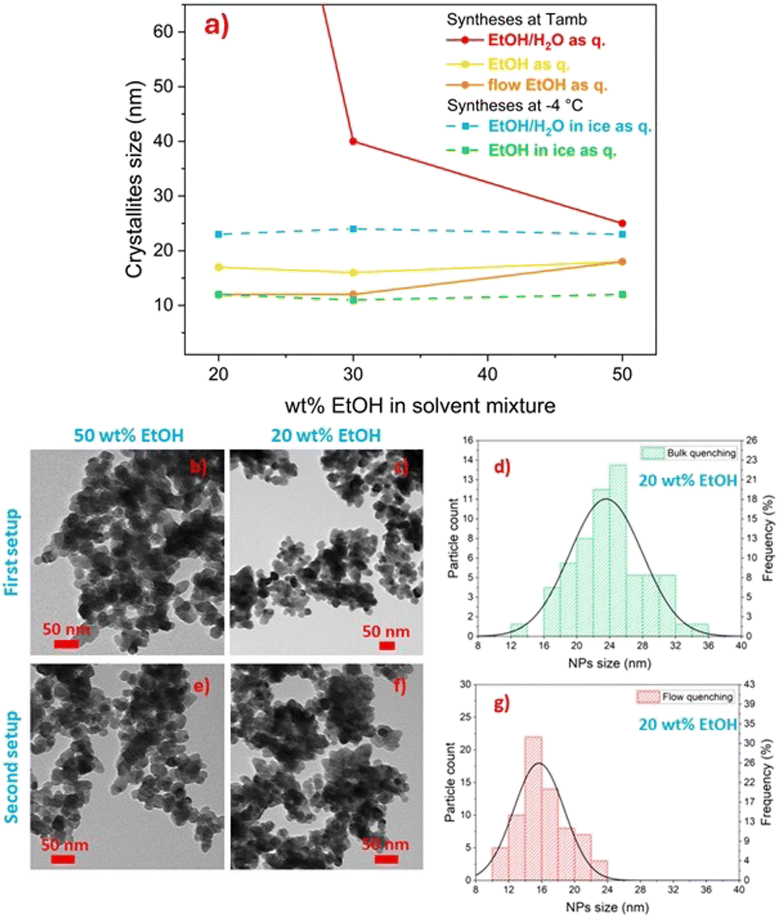 | ||
| Fig. 4 (a) Mean crystallite size of CM as a function of ethanol content in the solvent mixture, reaction temperature and quenching method, employing both the first setup (i.e. bulk quenching: red, yellow, cyan and green dots) and second setup (i.e. in flow quenching: orange dots). (b and c) TEM micrograph of samples prepared with the first setup in 50 wt% EtOH (b) and 20 wt% EtOH (c) and (d) relative particle size distribution (20 wt%). (e and f) TEM micrograph of samples prepared with the second setup in 50 wt% EtOH (e) and 20 wt% EtOH (f) and (g) relative particle size distribution (20 wt%). | ||
In order (i) to further improve the effectiveness of the quenching of calcium molybdate NP growth and aggregation, (ii) to fully exploit the highly efficient mixing ensured by microfluidics, and at the same time (iii) to keep constant throughout the entire run of the synthesis the viscosity and dielectric constant of the medium after the quenching step as well as the dilution factor of the reaction mixture, the quenching step of the reaction was implemented in flow. The first setup was modified into the second setup by adding a third syringe pump and a second micromixer (second setup, Fig. 2b) to efficiently mix the reaction mixture with the quencher, i.e. pure ethanol, and the amount of ethanol in the solvent mixture was varied from 20 to 50 wt%.
Diffraction data were collected for the synthesised samples, and the crystallite size was estimated to be in the 11–16 nm range (Fig. 4a, orange line), while the crystallite size of analogous samples obtained with bulk quenching ranged from 14 to 17 nm (Fig. 4a, yellow line). Similar to the products obtained with bulk ethanol quenching and also with flow quenching, spherical independent nanoparticles, not aggregated into larger microstructures, were obtained (Fig. 4e and f). However, a smaller and narrower NP size distribution was observed with flow quenching with respect to bulk quenching, particularly evident for particles obtained with 20 wt% ethanol in the reaction mixture, being 16 ± 3 nm (Fig. 4g) compared to 24 ± 4 nm (Fig. 4d). The possibility of keeping constant the amount of water in the mixture for the first and last droplets of reaction mixture provided homogeneity experienced by the reaction mixture throughout the whole synthesis (i.e. constant viscosity of the reaction environment in the collecting beaker). The narrowing of the particle size distribution was evident for all the samples (Fig. S3†), but it was more effective for the particles synthesised with 20 wt% ethanol in the reaction solvent. This observation was likely due to the fact that a low ethanol concentration in the reaction mixture (20 wt%) was less effective in halting particle aggregation, and thus the effect of flow quenching could be appreciated more than for samples synthesised with a higher ethanol content. The sudden increase in solvent viscosity and decrease in CM solubility occurring in the second T-junction mixer, which combined the flowing reaction mixture and pure ethanol, allowed an effective quenching of the reaction and avoided the aggregation of primary calcium molybdate nanoparticles into microstructures.
Comparing samples produced with the same solvent mixture composition and quenching method but different reaction temperatures (−4 °C vs. room temperature), it was observed that CM with smaller crystallite size was formed at −4 °C (Fig. 4a). Unlike what observed at room temperature, at −4 °C the influence of the ethanol concentration on the crystallite size could no longer be appreciated, also when Milli-Q water/ethanol mixtures were employed as quencher, yielding comparable values irrespective of the solvent mixture composition, likely due to the dramatic decrease of CM solubility. Moreover, as shown in Fig. 5, similarly to the room temperature counterparts when Milli-Q water/ethanol mixtures were employed as quencher, particles aggregated to microstructures with different morphologies according to the wt% ethanol in the solvent, whilst when ethanol was used as quencher, independent and well-defined nanoparticles were obtained. The effect of quenching on particle aggregation observed for the samples synthesised at −4 °C was the same as for the samples prepared at room temperature. However, the nanoparticles obtained at −4 °C, with ethanol as quencher, display a narrower size distribution (PDI = 0.16) with respect to the samples obtained at room temperature (PDI = 0.25, Fig. 6).
 | ||
| Fig. 5 SEM and TEM images of CM samples obtained at 20 °C and at −4 °C with the first setup, and varying the content of ethanol in the solvent mixture and quenching method. | ||
 | ||
| Fig. 6 Particle size distribution obtained at −4 °C (a) and at 20 °C (b) with 30 wt% ethanol in the reaction mixture and ethanol as quencher. | ||
In general, conducting the synthesis at lower temperatures facilitated a more precise formation of CM particles, evident in the more uniformly shaped microstructures observed (Fig. 5). This outcome is likely attributable to the lower solubility and to the increased viscosity of the reaction mixture, a parameter predominantly affected by temperature (Fig. S1†), thereby impacting the modified diffusion coefficient (following the Stokes–Einstein relation). Furthermore, considering the varied aggregate morphologies observed with different ethanol concentrations at both ambient and lower temperatures, it can be inferred that the dielectric constant assumes a primary role in determining the ultimate aggregate morphology. This is due to its influence on the formation of surface charges and the relative alignment of primary particles, as previously suggested.
Synthesis of Eu(III)-doped calcium molybdate
To demonstrate the effectiveness of the microfluidic approach to dope calcium molybdate, the synthesis of Eu(III)-doped CM was also performed under microfluidic conditions. As thoroughly described in the experimental part, three samples of 3 at% Eu(III)-doped CaMoO4 were synthesised by adding a stoichiometric amount of Eu3+ precursor into the Ca2+ precursor solution, and operating under three different sets of synthetic conditions previously employed for the synthesis of undoped CM. The doping percentage was chosen to test the versatility of the synthetic method, and as optimal concentration for obtaining enhanced optical properties without spurious species, as observed in our previous work.20 In particular, the synthetic conditions were chosen according to the synthetic outcome features, in terms of particle size and size distribution. Eu-doped CM was synthesised by employing 50 wt% EtOH/water as solvent mixture and:(i) First setup at ambient temperature, quenching the product by dilution with an excess of ethanol in the collecting vessel (sample Eu:CM_01);
(ii) First setup at −4 °C, quenching the product by dilution with an excess of ethanol in the collecting vessel kept in the −4 °C cold bath (sample Eu:CM_02);
(iii) Second setup at ambient temperature, quenching inline the product by dilution in ethanol (sample Eu:CM_03).
In order to determine the actual amount of Eu(III) in the samples and to assess the doping percentage, ICP-MS analysis was performed. Results are reported in Table 1 and show that the at% of europium in the doped samples is almost equal to the expected at%, thus highlighting the effectiveness of doping with all the employed experimental setups. The ICP-MS measurements revealed a slightly higher doping at% with respect to the expected one, probably due to a loss of molybdenum during the purification step.
| Sample | at% (expected) | at% (ICP) |
|---|---|---|
| Eu:CM_01 | 2.97 | 3.25(0.31) |
| Eu:CM_02 | 3.00 | 3.25(0.31) |
| Eu:CM_03 | 3.00 | 3.27(0.31) |
The XRD characterisation of the materials revealed that the crystalline structure of CM was preserved after the 3 at% doping, as crystallisation of tetragonal scheelite-type CaMoO4 was detected under all synthetic conditions, with no crystalline spurious phase formation (Fig. S4†). No spurious reflections ascribed to impurities were found, likely indicating a successful doping (i.e. the Eu3+ ions actually substituted Ca2+ ions in the crystal structure, as reported in our previous study20). The introduction of Eu3+ doping ions in the samples, confirmed by ICP-MS, had no relevant effect on the average crystallite size estimated by the Pawley refinement method: crystallite size values of 15 nm (Tamb, EtOH as quencher), 9 nm (T = −4 °C, EtOH as quencher) and 14 nm (Tamb, flow EtOH as quencher) for Eu(III)-doped CM produced under identical experimental conditions were obtained (17, 10, 16 nm crystallite size was obtained for the undoped samples). Independent nanoparticles were detected by TEM micrographs (Fig. S5†) of the sample synthesised at −4 °C, like in the analogous undoped CM sample. However, a few spindle-like aggregates in the 100–200 nm range were observed in TEM micrographs of the doped samples synthesised at room temperature quenching the reaction mixture in bulk (Eu:CM_01, first setup) and in flow (Eu:CM_03, second setup). Since the formation of such aggregates was not observed at −4 °C (sample Eu:CM_02), this confirmed that performing the synthesis at low temperature allowed a better control over nanoparticle aggregation, most likely due to the strongly increased viscosity of the reaction mixture and sudden decrease in solubility of the product.
Finally, to assess whether the structural features of the doped samples affected their optical properties as well as to assess the effectiveness of the doping, optical absorption and photoluminescence measurements on powders were performed. In particular, the absorption spectra of the samples were evaluated through UV-vis diffuse reflectance, while excitation and emission spectra were recorded as well as photoluminescence lifetime and emission quantum yield.
The bandgap energy estimated for the doped samples was 4.2 eV for all samples, comparable to literature data5,20 (Tauc plots reported in Fig. S8†).
The excitation spectra of three samples doped with Eu3+, acquired by monitoring the emission of Eu3+ ions (λem = 612 nm), are reported in Fig. 7a. Two distinct excitation contributions were observed: the broad and intense band in the region 250–330 nm was assigned to a combination of charge transfer (CT) transitions from [MoO4]2− and [Mo2O7]2− groups to Eu3+ ions,8,72 and several sharp peaks at higher wavelengths ascribed to direct Eu3+ f–f absorption. The most intense lines were at 395 and 465 nm, due to 7F0 → 5L6 and 7F0 → 5D2 transitions, respectively. For all the samples, the f–f transition peak intensity was lower than the intensity of the CT band, suggesting that the electron transfer from the MoO42− group towards Eu3+ was efficient,73,74 and therefore that the doping process was likely effective. While the lines due to f → f Eu3+ absorption were quite similar for the three samples, a shoulder at 310 nm was observed in the CT excitation band of the Eu:CM_02 sample (i.e. synthesised at low temperature), not evident in other samples. It is already known that a red-shift of the CT band can be an effect of a weaker extent of covalence on the Eu3+–O2− bond, since it is more difficult for the electron to transfer to the free Eu3+ 4f state within the host CaMoO4 matrix. The change in the local microstructure around Eu3+, sometimes induced by co-doping with different alkaline earth metals (i.e. a well-known mechanism of charge compensation in CaMoO4 doped with trivalent ions such as Eu3+), and the increase in the cell volume or particle size, are mainly responsible for the red-shift of the CT band.73–76
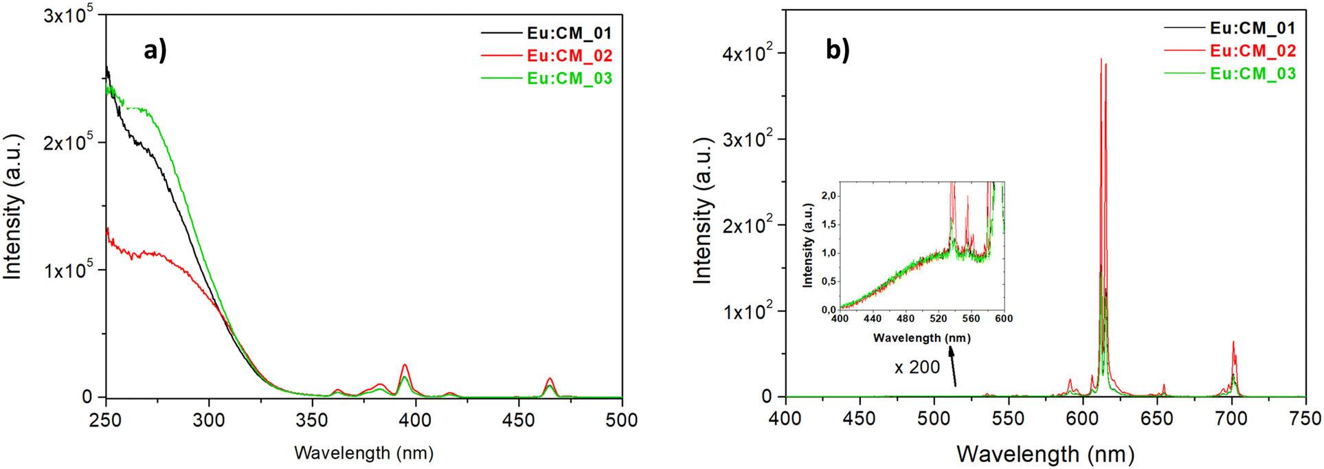 | ||
| Fig. 7 (a) Excitation spectra of the three Eu(III)-doped calcium molybdate samples (λem = 612 nm). (b) Emission spectra of the three samples under 285 nm excitation. Inset: Enlargement of the region 400–600 nm. | ||
Fig. 7b shows the emission spectra of the three nanophosphors under 285 nm excitation (i.e. excitation of the matrix CaMoO4). The emission spectra for all CaMoO4:Eu3+ phosphors consisted of typical emission lines of Eu3+ and a very weak residual emission band of host material at 520 nm (see Fig. 7b, inset), suggesting a good energy transfer from the matrix to Eu3+ ions. For all the samples, the most intense emission signal was at 612–615 nm, attributed to the hypersensitive electric dipole transition 5D0 → 7F2 of Eu3+ that is known to be highly sensitive to the surroundings of Eu3+ ions, and it occurs only when Eu3+ is located in a non-centrosymmetric site. Since the peak shape was similar for all samples, it can be stated that the local environment was the same even if the synthesis procedure was different, and in particular a non-centrosymmetric site of the Eu3+ ion could be supposed for all samples. The other transitions, such as 5D0 → 7F1 (magnetic dipole transition at 592 nm, sensitive to symmetric sites) and 5D0 → 7F3, 5D0 → 7F4 located in the range of 530–710 nm, were weak.77,78 From the calculation of the asymmetry ratio, defined as the ratio between the integrated area under the 5D0 → 7F2 and the 5D0 → 7F1 signal, it was possible to measure indirectly the degree of distortion of the local surroundings of the Eu3+ site. The asymmetry ratios ranged from 9.5 to 11.7 (Table 2). Such high asymmetry ratio values (even larger than the values reported in the literature79,80) were a proof that in all phosphors, the Eu3+ occupied the Ca2+ site in the lattice that lacked inversion symmetry, such as in the scheelite tetragonal structure, thus that the doping of calcium molybdate with Eu3+ was efficient with the employed microfluidic setups. In addition, a higher (5D0 → 7F2)/(5D0 → 7F1) value indicated better color purity, a feature which is useful for their application in LED technologies. By comparing the three Eu-doped samples synthesised with different sets of synthetic conditions, the sample synthesised at low temperature (Eu:CM_02, red plot, Fig. 7) was observed to be characterised by the highest emission intensity. This agreed with the highest fluorescence quantum yield (FQY) measured for this powder (Table 2), suggesting that the microstructure of the particles in the Eu:CM_02 sample had a stronger impact in reducing the non-radiative decay paths, or quenching centers (traps), with respect to other samples.8,24,81
| Sample | τ 1 (μs) | τ 2 (μs) | Asymmetry ratio | FQY (%) |
|---|---|---|---|---|
| Eu:CM_01 | 483 (50%) | 953 (50%) | 9.7 | 9.0 |
| Eu:CM_02 | 347 (32%) | 837 (68%) | 11.7 | 13.9 |
| Eu:CM_03 | 480 (47%) | 930 (53%) | 9.5 | 9.5 |
The photoluminescence decay curves of the three phosphors upon excitation at 285 nm (Fig. S6†) of the 5D0 → 7F2 transition of Eu3+ ions at 612 nm can be well fitted with a double exponential function:
| I(t) = A1e−t/τ1 + A2e−t/τ2 |
Even if in the literature the decay of Eu3+-doped phosphors is mono-exponential,72,73,78,82 it is quite usual for particles having high surface-to-volume ratio to have multi-exponential decays. The measured lifetimes (Table 2) were anyway in the same range found for Eu3+ compound lifetimes. Eu:CM_01 and Eu:CM_03 were characterised by the same lifetime and amplitude values, while for Eu:CM_02 the longer lifetime had a higher relative amplitude. This was consistent with previous comments on the higher fluorescence efficiency characterising the Eu:CM_02 phosphor and with the results we obtained in our previous work.20
Conclusions
Undoped and Eu(III)-doped calcium molybdate particles ranging from nano- to microstructures were successfully synthesised by exploiting a novel microfluidic route. The stages of particle formation and aggregation were investigated through a systematic variation of the dielectric constant and viscosity of the reaction medium as well as the temperature of the reaction mixture.The obtained results were correlated to the most acknowledged models of nucleation and growth of LaMer–Dinegar and Sugimoto–Chu. The microfluidic approach turned out to be particularly suitable in finely tuning synthetic conditions, in an easy and effective way, by just exploiting Milli-Q water/ethanol mixed solvents as reaction environment, playing with the implementation of a quenching step in different ways, and with the temperature control offered by high surface/volume ratio of the reactor. In particular, the effect of the ethanol content in the solvent mixture was observed to dramatically affect crystallite size as well as particle aggregation into microstructures with different morphologies. A remarkable effect was played by the quenching step, which was crucial in limiting particle growth and aggregation and in obtaining primary nanoparticles, by changing quencher composition (e.g. solvent mixture or ethanol) and/or temperature. The possibility of effectively doping CM with Eu(III) under microfluidic conditions was demonstrated by ICP-MS, XRD and photoluminescence properties. Indeed, doped samples showed notable optical properties, which allowed us to hypothesise the inclusion of Eu(III) ions in the CM crystal lattice, replacing calcium cations, leading to good quantum yield, and marking these systems suitable in applications as phosphor. In this regard, we are confident that our synthetic approach could be employed for the synthesis of CM doped with other Ln ions by simply introducing different Ln3+ ions in the microfluidic system as well as different doping percentages by varying the concentration of the dopant ion solution. Indeed, we have already demonstrated in our previous studies how versatile a microfluidic system can be in terms of readily adjusting the reaction conditions to obtain products with customised properties and controlled stoichiometry.38
The role of the microfluidic setup (i.e. experimental conditions) in the functional properties was also explored, evidencing how reaction temperature plays a major role in controlling product features in terms of crystallite size, particle size and aggregation.
Data availability
The data supporting this article have been included as part of the ESI.†Author contributions
Pietro Ostellari: synthesis, characterisation, data analysis, writing – original draft. Francesca Tajoli: conceptualisation, characterisation, writing and reviewing. Ilaria Fortunati: characterisation and writing. Tommaso Carofiglio: support for microfluidic synthesis. Denis Badocco: characterisation. Paolo Pastore: characterisation. Silvia Gross: original conceptualisation and idea, supervision, funding, writing and reviewing.Conflicts of interest
There are no conflicts to declare.Acknowledgements
We gratefully thank Dr. Francesco Boldrin and Dr. Federico Caicci of the Department of Biology, University of Padova, Italy, for TEM analyses.References
- M. Ghaed-Amini, M. Bazarganipour and M. Salavati-Niasari, J. Ind. Eng. Chem., 2015, 21, 1089–1097 CrossRef CAS.
- A. Phuruangrat, T. Thongtem and S. Thongtem, J. Alloys Compd., 2009, 481, 568–572 CrossRef CAS.
- Y. Yin, Y. Gao, Y. Sun, B. Zhou, L. Ma, X. Wu and X. Zhang, Mater. Lett., 2010, 64, 602–604 CrossRef CAS.
- J. A. Groenink, C. Hakfoort and G. Blasse, Phys. Status Solidi, 1979, 54, 329–336 CrossRef CAS.
- V. M. Longo, A. T. De Figueiredo, A. B. Campos, J. W. M. Espinosa, A. C. Hernandes, C. A. Taft, J. R. Sambrano, J. A. Varela and E. Longo, J. Phys. Chem. A, 2008, 112, 8920–8928 CrossRef CAS PubMed.
- L. K. Bharat, G. S. R. Raju and J. S. Yu, Sci. Rep., 2017, 7, 1–14 CrossRef CAS PubMed.
- M. Nirmal and L. Brus, Acc. Chem. Res., 1999, 32, 407–414 CrossRef CAS.
- Y. Wang, J. Song, Y. Zhao, L. Xu, D. He and H. Jiao, Powder Technol., 2015, 275, 1–11 CrossRef CAS.
- W. Wang, Y. Hu, J. Goebl, Z. Lu, L. Zhen and Y. Yin, J. Phys. Chem. C, 2009, 113, 16414–16423 CrossRef CAS.
- Z. J. Kiss and R. J. Pressley, Proc. IEEE, 1966, 54(10), 1236–1248 Search PubMed.
- A. K. Parchur, R. S. Ningthoujam, S. B. Rai, G. S. Okram, R. A. Singh, M. Tyagi, S. C. Gadkari, R. Tewari and R. K. Vatsa, Dalton Trans., 2011, 40, 7595–7601 RSC.
- R. Saraf, C. Shivakumara, N. Dhananjaya, S. Behera and H. Nagabhushana, J. Mater. Sci., 2015, 50, 287–298 CrossRef CAS.
- W. A. Crichton and A. Grzechnik, Z. Kristallogr., 2004, 219, 337–338 CAS.
- V. B. Aleksandrov, L. V. Gorbatyi and V. V. Ilyukhin, Sov. Phys. Crystallogr., 1968, 13, 414–415 Search PubMed.
- A. B. Campos, A. Z. Simões, E. Longo, J. A. Varela, V. M. Longo, A. T. De Figueiredo, F. S. De Vicente and A. C. Hernandes, Appl. Phys. Lett., 2007, 91, 2005–2008 CrossRef.
- W. A. Crichton and A. Grzechnik, Z. Kristallogr., 2004, 219, 337–338 CAS.
- B. G. Soares, S. Caplan, S. Livi, A. Gatti and S. J. L. Ribeiro, J. Mater. Sci., 2015, 50, 2903–2913 CrossRef CAS.
- V. B. Aleksandrov, L. V. Gorbatyi and V. V. Ilyukhin, Sov. Phys. Crystallogr., 1968, 13, 414–415 Search PubMed.
- A. I. Becerro, M. Allix, M. Laguna, D. González-Mancebo, C. Genevois, A. Caballero, G. Lozano, N. O. Núñez and M. Ocaña, J. Mater. Chem. C, 2018, 6, 12830–12840 RSC.
- C. Mazzariol, F. Tajoli, A. E. Sedykh, P. Dolcet, J. D. Grunwaldt, K. Muller-Buschbaum and S. Gross, ACS Appl. Nano Mater., 2023, 6, 15510–15520 CrossRef CAS.
- R. D. Shannon, Acta Crystallogr., Sect. A: Found. Adv., 1976, 32, 751–767 CrossRef.
- M. Laguna, N. O. Nuñez, A. I. Becerro and M. Ocaña, CrystEngComm, 2017, 19, 1590–1600 RSC.
- F. Lei and B. Yan, J. Solid State Chem., 2008, 181, 855–862 CrossRef CAS.
- X. Liu, L. Li, H. M. Noh, J. H. Jeong, K. Jang and D. S. Shin, RSC Adv., 2015, 5, 9441–9454 RSC.
- A. Bayat, A. R. Mahjoub and M. M. Amini, Mater. Chem. Phys., 2019, 223, 583–590 CrossRef CAS.
- J. H. Ryu, J. W. Yoon, C. S. Lim, W. C. Oh and K. B. Shim, J. Alloys Compd., 2005, 390, 245–249 CrossRef CAS.
- V. S. Marques, L. S. Cavalcante, J. C. Sczancoski, A. F. P. Alcântara, M. O. Orlandi, E. Moraes, E. Longo, J. A. Varela, M. Siu Li and M. R. M. C. Santos, Cryst. Growth Des., 2010, 10, 4752–4768 CrossRef CAS.
- J. Ho Ryu, B. Geun Choi, J. W. Yoon, K. Bo Shim, K. Machi and K. Hamada, J. Lumin., 2007, 124, 67–70 CrossRef.
- Y. Yang, X. Li, W. Feng, W. Yang, W. Li and C. Tao, J. Alloys Compd., 2011, 509, 845–848 CrossRef CAS.
- D. Chen, K. Tang, F. Li and H. Zheng, Cryst. Growth Des., 2006, 247–252 CrossRef CAS.
- W. Wang, L. Zhen, W. Shao and Z. Chen, CrystEngComm, 2014, 16, 2598–2604 RSC.
- Q. Gong, X. Qian, X. Ma and Z. Zhu, Cryst. Growth Des., 2006, 6, 1821–1825 CrossRef CAS.
- H. Cölfen and M. Antonietti, Mesocrystals and Nonclassical Crystallization, John Wiley & Sons, London, 2008 Search PubMed.
- A. M. Nightingale and J. C. De Mello, J. Mater. Chem., 2010, 20, 8454–8463 RSC.
- A. M. Nightingale, J. H. Bannock, S. H. Krishnadasan, F. T. F. O'Mahony, S. A. Haque, J. Sloan, C. Drury, R. McIntyre and J. C. Demello, J. Mater. Chem. A, 2013, 1, 4067–4076 RSC.
- J. DeMello and A. DeMello, Lab Chip, 2004, 4, 11–15 RSC.
- K. S. Elvira, X. C. I Solvas, R. C. R. Wootton and A. J. Demello, Nat. Chem., 2013, 5, 905–915 CrossRef CAS PubMed.
- F. Tajoli, N. Dengo, M. Mognato, P. Dolcet, G. Lucchini, A. Faresin, J. D. Grunwaldt, X. Huang, D. Badocco, M. Maggini, C. Kübel, A. Speghini, T. Carofiglio and S. Gross, ACS Appl. Mater. Interfaces, 2020, 12, 44074–44087 CrossRef CAS PubMed.
- S. H. Wong, M. C. L. Ward and C. W. Wharton, Sens. Actuators, B, 2004, 100, 359–379 CrossRef CAS.
- C. Y. Lee, C. L. Chang, Y. N. Wang and L. M. Fu, Int. J. Mol. Sci., 2011, 12, 3263–3287 CrossRef CAS PubMed.
- V. Hessel, H. Löwe and F. Schönfeld, Chem. Eng. Sci., 2005, 60, 2479–2501 CrossRef CAS.
- I. Lignos, L. Protesescu, S. Stavrakis, L. Piveteau, M. J. Speirs, M. A. Loi, M. V. Kovalenko and A. J. DeMello, Chem. Mater., 2014, 26, 2975–2982 CrossRef CAS.
- P. Zardi, T. Carofiglio and M. Maggini, Chem. – Eur. J., 2022, 28, e202103132 CrossRef CAS PubMed.
- N. Dengo, A. Faresin, T. Carofiglio, M. Maggini, L. Wu, J. P. Hofmann, E. J. M. Hensen, P. Dolcet and S. Gross, Chem. Commun., 2020, 56, 8707–8710 RSC.
- P. T. Anastas and J. C. Warner, Green Chemistry: Theory and Practice, Oxford University Press, New York, United States of America, 1998 Search PubMed.
- J. J. Cruywagen, Adv. Inorg. Chem., 1999, 49, 127–182 CrossRef.
- J. Wegner, S. Ceylan and A. Kirschning, Chem. Commun., 2011, 47, 4583–4592 RSC.
- M. B. Plutschack, B. Pieber, K. Gilmore and P. H. Seeberger, Chem. Rev., 2017, 117, 11796–11893 CrossRef CAS PubMed.
- G. S. Pawley, J. Appl. Crystallogr., 1981, 14, 357–361 CrossRef CAS.
- C. A. Schneider, W. S. Rasband and K. W. Eliceiri, Nat. Methods, 2012, 9, 671–675 CrossRef CAS.
- P. Kubelka and F. Munk, Z. Technol. Phys., 1931, 12, 593–599 Search PubMed.
- I. Lavagnini, D. Badocco, P. Pastore and F. Magno, Talanta, 2011, 87, 180–188 CrossRef CAS PubMed.
- V. K. LaMer, Ind. Eng. Chem., 1952, 44, 1270–1277 CrossRef CAS.
- V. K. LaMer and R. H. Dinegar, J. Am. Chem. Soc., 1950, 72, 4847–4854 CrossRef CAS.
- Y. Song, H. Modrow, L. L. Henry, C. K. Saw, E. E. Doomes, V. Palshin, J. Hormes and C. S. S. R. Kumar, Chem. Mater., 2006, 18, 2817–2827 CrossRef CAS.
- A. Einstein, Ann. Phys., 1905, 4, 549–560 CrossRef.
- P. C. Hiemenz and R. Rajagopalan, Principles of Colloid and Surface Chemistry, CRC Press, Boca Raton, 1997 Search PubMed.
- W. M. Haynes, D. R. Lide and T. J. Bruno, Handbook of Chemistry and Physics, CRC Press, Boca Raton, 2017 Search PubMed.
- I. S. Khattab, F. Bandarkar, M. A. A. Fakhree and A. Jouyban, Korean J. Chem. Eng., 2012, 29, 812–817 CrossRef CAS.
- A. Jouyban and S. Soltanpour, J. Chem. Eng. Data, 2010, 55, 2951–2963 CrossRef CAS.
- T. Sugimoto, Chem. Eng. Technol., 2003, 26, 313–321 CrossRef CAS.
- T. Sugimoto, F. Shiba, T. Sekiguchi and H. Itoh, Colloids Surf., A, 2000, 164, 183–203 CrossRef CAS.
- D. B. K. Chu, J. S. Owen and B. Peters, J. Phys. Chem. A, 2017, 121, 7511–7517 CrossRef CAS PubMed.
- S. Busch, H. Dolhaine, A. DuChesne, S. Heinz, O. Hochrein, F. Laeri, O. Podebrad, U. Vietze, T. Weiland and R. Kniep, Eur. J. Inorg. Chem., 1999, 1643–1653 CrossRef.
- R. Kniep and S. Busch, Angew. Chem., Int. Ed. Engl., 1996, 35, 2624–2626 CrossRef CAS.
- H. Cölfen and M. Antonietti, Angew. Chem., Int. Ed., 2005, 44, 5576–5591 CrossRef PubMed.
- R. L. Fogel'son and E. R. Likhachev, Tech. Phys., 2001, 46, 1056–1059 CrossRef.
- G. T. Hefter and R. P. T. Tomkins, The Experimental Determination of Solubilities, John Wiley & Sons, Ltd, Chichester, England, 2003 Search PubMed.
- A. Jouyban, M. Khoubnasabjafari, Z. Vaez-Gharamaleki, Z. Fekari and W. E. Acree, Chem. Pharm. Bull., 2005, 53, 519–523 CrossRef CAS PubMed.
- N. A. A. Mumallah and W. J. Popiel, Anal. Chem., 1974, 46, 2055–2056 CrossRef CAS.
- T. P. Dadze, G. A. Kashirtseva, M. P. Novikov and A. V. Plyasunov, Monatsh. Chem., 2018, 149, 261–282 CrossRef CAS.
- M. Janulevicius, P. Marmokas, M. Misevicius, J. Grigorjevaite, L. Mikoliunaite, S. Sakirzanovas and A. Katelnikovas, Sci. Rep., 2016, 6, 1–12 CrossRef PubMed.
- Y. Xie, S. Ma, Y. Wang, M. Xu, C. Lu, L. Xiao and S. Deng, Opt. Mater., 2018, 77, 13–18 CrossRef CAS.
- P. S. Dutta and A. Khanna, ECS J. Solid State Sci. Technol., 2013, 2, R3153–R3167 CrossRef CAS.
- S. K. Gupta, M. Sahu, P. S. Ghosh, D. Tyagi, M. K. Saxena and R. M. Kadam, Dalton Trans., 2015, 44, 18957–18969 RSC.
- S. Wei, L. Yu, F. Li, J. Sun and S. Li, Ceram. Int., 2015, 41, 1093–1100 CrossRef CAS.
- A. John Peter, I. B. Shameem Banu, J. Thirumalai and S. P. David, J. Mater. Sci.: Mater. Electron., 2013, 24, 4503–4509 CrossRef.
- M. L. A. Letswalo, L. Reddy, A. Balakrishna, H. C. Swart and O. M. Ntwaeaborwa, J. Alloys Compd., 2021, 854, 157022 CrossRef CAS.
- H. Wu, Y. Hu, W. Zhang, F. Kang, N. Li and G. Ju, J. Sol-Gel Sci. Technol., 2012, 62, 227–233 CrossRef CAS.
- M. Lei, C. X. Ye, S. S. Ding, K. Bi, H. Xiao, Z. B. Sun, D. Y. Fan, H. J. Yang and Y. G. Wang, J. Alloys Compd., 2015, 639, 102–105 CrossRef CAS.
- A. Vanetsev, K. Kaldvee, L. Puust, K. Keevend, A. Nefedova, S. Fedorenko, A. Baranchikov, I. Sildos, M. Rähn, V. Sammelselg and Y. Orlovskii, ChemistrySelect, 2017, 2, 4874–4881 CrossRef CAS.
- R. L. Ayscue, C. P. Verwiel, J. A. Bertke and K. E. Knope, Inorg. Chem., 2020, 59, 7539–7552 CrossRef CAS PubMed.
Footnote |
| † Electronic supplementary information (ESI) available. See DOI: https://doi.org/10.1039/d4ce00549j |
| This journal is © The Royal Society of Chemistry 2024 |