
 Open Access Article
 This Open Access Article is licensed under a Creative Commons Attribution-Non Commercial 3.0 Unported Licence
The importance of electrolyte environment during in situ self-transformation for synthesizing V2O5·nH2O†
Haijia
Quan
 ,
Chen
Wang
,
Dongxu
Guo
,
Xiaofeng
Wang
,
Chenglin
Sun
* and
Shenghan
Wang
*
,
Chen
Wang
,
Dongxu
Guo
,
Xiaofeng
Wang
,
Chenglin
Sun
* and
Shenghan
Wang
*
Key Laboratory of Physics and Technology for Advanced Batteries, College of Physics, Jilin University, Changchun 130012, P. R. China. E-mail: shenghan@jlu.edu.cn
First published on 11th January 2024
Abstract
V2O5·nH2O is a promising cathode material for zinc-ion batteries. One of the synthesis methods of V2O5·nH2O is in situ self-transformation. In this communication, we focus on the influence of the electrolyte environment during in situ self-transformation (from VO2 to V2O5·nH2O). 2 M ZnSO4 and 2 M Zn(OTf)2 were used as different electrolytes to produce VOH-1 and VOH-2. VOH-1 expands in volume along the electric field to form a porous surface structure and shows low crystallinity along the (0 0 1) plane, while VOH-2 exhibits the opposite. These advantages enable the assembled batteries with VOH-1 to maintain excellent cycling performance at a rate of 2 A g−1 with a capacity of 500 mA h g−1 and stable cycling for 1800 cycles.
Zinc-ion batteries have garnered considerable attention because of their environmental friendliness, safety and cost effectiveness. However, several significant challenges must be addressed before practical applications can be realized. Among these challenges, the development of cathode materials, a crucial component in zinc-ion batteries, takes precedence. Notably, V2O5·nH2O emerges as one of the most promising candidates, attracting wide interest.1–5 As a representative layered material, V2O5·nH2O exhibits an excellent interlayer structure (between the (0 0 1) planes) to accommodate Zn2+.6–10 The H2O between the (0 0 1) planes stabilizes the primary structure of V2O5·nH2O and significantly reduces electrostatic repulsive force through a “charge shield effect”.7,8
Unlike conventional synthesis methods, in situ self-transformation oxidizes V4+ to V5+ electrochemically. In certain cases, structural H2O can be incorporated into newly formed materials.11,12 However, researchers have focused mainly on the control of precursors, while the regulation of the electrolyte environment during in situ self-transformation has been largely overlooked.13,14 It is much simpler to adjust the electrolyte environment than to create a better precursor. Producing V2O5·nH2O through adjusting the electrolyte environment eliminates complicated synthesis steps.
This work used 2 M ZnSO4 and 2 M Zn(OTf)2 as electrolytes during in situ self-transformation, resulting in distinct V2O5·nH2O. The importance of the electrolyte environment during in situ self-transformation for synthesizing V2O5·nH2O is demonstrated by contrasting the differences between VOH-1 and VOH-2. Through the analysis of the morphology and structure, we discover that VOH-1 has a porous surface structure, expanded volume and lower crystallinity along the (0 0 1) plane. VOH-1 exhibits a tendency to grow along the electric field. On the contrary, VOH-2 shows a reduction in volume and higher crystallinity along the (0 0 1) plane. The electrochemical characterization further illustrates the importance of the electrolyte environment during in situ self-transformation.
The precursor of in situ self-transformation was synthesized following a previously established protocol.15 The SEM images of the VO2 powder and VO2 electrode revealed that VO2 is well dispersed in super P (Fig. S1a1, a2, b1 and b2, ESI†). Dark clusters are identified as super P. The XRD pattern of the VO2 powder is well indexed to VO2 (PDF#04-007-2429) (Fig. S2a1, ESI†). After the VO2 electrode was prepared, the XRD peaks of the (1 1 0), (2 2 0) and (3 3 0) planes exhibit higher intensity, resulting from crystal orientation caused by the electrode preparation process (Fig. S2a2, ESI†). The Raman spectra of VO2 are consistent with previous reports (Fig. S2b1 and b2, ESI†).16,17 The peaks at 284 and 408 cm−1 correspond to the bending vibrations of V![[double bond, length as m-dash]](https://www.rsc.org/images/entities/char_e001.gif) O. The peaks at 522 cm−1 and 695 cm−1 correspond to the stretching vibrations of V3–O and V2–O. Furthermore, the peak at 993 cm−1 is attributed to the terminal VO bond. The XPS spectra of VO2 reveal a minor presence of V5+ (Fig. S2c1 and c2, ESI†).
O. The peaks at 522 cm−1 and 695 cm−1 correspond to the stretching vibrations of V3–O and V2–O. Furthermore, the peak at 993 cm−1 is attributed to the terminal VO bond. The XPS spectra of VO2 reveal a minor presence of V5+ (Fig. S2c1 and c2, ESI†).
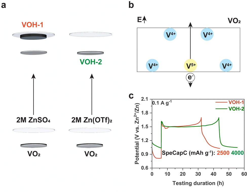
This work performed in situ self-transformation in a cell for better repeatability (Fig. 1a and b). The schematic illustration of battery disassembly and the photo of VOH-1 are provided to facilitate a better understanding of in situ self-transformation (Fig. S3a and b, ESI†). Each cell included 80 μl electrolyte and stood for 6 h to reach a steady state before in situ self-transformation. A current density of 0.1 A g−1 was used to complete in situ self-transformation. After a simple test, we opted for a cut-off voltage of 1.7 V and a direct charging scheme (Fig. S3c and d, ESI†). After in situ self-transformation, we observed the detachment of VOH-1 from the current collector. The detachment is due to the poor adhesion of PVDF in 2 M ZnSO4 and was also observed in the cells standing for 24 h (Fig. S4, ESI†).
 | ||
| Fig. 1 In situ self-transformation. (a) The schematic diagram. (b) The schematic diagram of VOH-1. (c) The time–potential curves. | ||
The time-potential curves of in situ self-transformation show that both VOH-1 and VOH-2 exhibited prolonged voltage plateaus (Fig. 1c). The number of electrons used to complete in situ self-transformation is much greater than that needed for the transition from V4+ to V5+ (about 300 mA h g−1).18 This implies that in situ self-transformation exhibits significant side reactions, which involve a gas generation process.19,20 We measured the thickness of cells before and after in situ self-transformation, recording 2.45–2.48 mm and 2.55–2.68 mm. The thickness of the cells expanded. This provides additional evidence that the side reactions involve a gas evolution process. The gas evolution process could lead to the formation of a porous structure. However, this process also occurred in VOH-2, where a porous surface structure did not form (Fig. 2a1 and b1). This reveals that 2 M ZnSO4 is responsible for the formation of a favorable surface morphology.
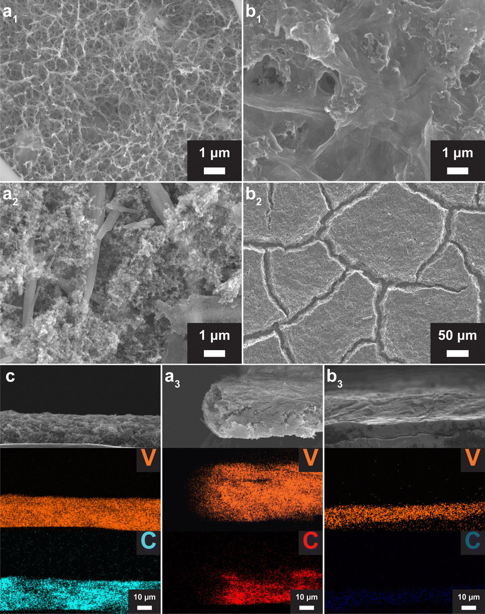 | ||
| Fig. 2 The morphological and compositional characterization. (a1) and (a2) The SEM images of VOH-1 and the reverse side. (b1) and (b2) The SEM images of VOH-2. (c), (a3) and (b3) The SEM-EDS elemental maps of the cross section of VO2, VOH-1 and VOH-2. | ||
We observed that VOH-1 has a close connection with GF and an exposed carbon framework on the reverse side (Fig. 2a2). To explain this phenomenon, we collected EDS elemental maps in the cross section (Fig. 2c, a3 and b3). Compared to the VO2 electrode, VOH-1 has expanded volume, while VOH-2 shows a reduction in volume. The formation of the divided morphology in VOH-2 is also because of that (Fig. 2b2). In the VO2 electrode, V and C were spread evenly. In VOH-1, the carbon framework is retained in the original position, while the V element is distributed within the expanded volume. This implies that in situ self-information in 2 M ZnSO4 has a tendency to grow along the electric field.
The XRD patterns of VOH-1 and VOH-2 are consistent with previous reports and can be indexed to V2O5·nH2O (PDF#00-007-0332) (Fig. 3a1 and b1).7,21,22 The TEM images of VOH-1 reveal 0.34 nm lattice fringes, corresponding to the (5 0 0) plane (Fig. S5, ESI†). The XRD peak of the (0 0 1) plane of VOH-1 is almost gone. This implies that the electrolyte environment alters the crystal growth orientation. The Raman spectra of VOH-1 and VOH-2 are consistent with previous reports (Fig. 3a2 and b2).2,20,21 The peak at 304 cm−1 corresponds to the bending vibration of VO. The peaks at 507 and 725 cm−1 correspond to the stretching vibrations of V3–O and V2–O. These three vibrations are related to the V–O main framework and have nearly the same position. This suggests that VOH-1 and VOH-2 have the same basic structure. The peak at 871 cm−1 corresponds to the stretching vibration of V–OH2. This shows that lattice water has been successfully put into the crystal lattice. The XPS spectra of VOH-1 and VOH-2 suggest the presence of V4+ (Fig. S6, ESI†).
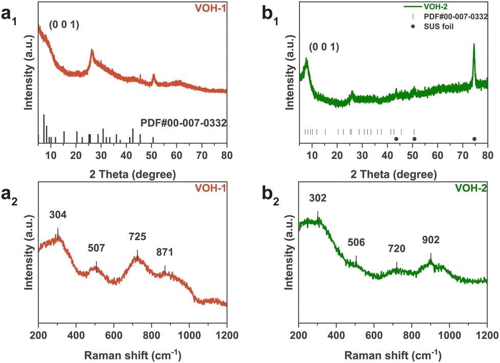 | ||
| Fig. 3 The structural characterization of VOH-1 and VOH-2. (a1) and (b1) XRD patterns. (a2) and (b2) Raman spectra. | ||
We proceeded to assemble batteries using VOH-1 and VOH-2, subjecting them to the following electrochemical tests with a voltage window from 0.3 to 1.5 V. The 2 M Zn(OTf)2 electrolyte was chosen, because it is commonly used in vanadium-based batteries. The electrolyte amount of 2 M Zn(OTf)2 was about 90 μl (Fig. S7, ESI†). The CV curves show two primary electrochemical platforms, which are consistent with the capacity-potential curves (Fig. 4a and b). VOH-2 has a pronounced voltage polarization between the oxidation peak and the reduction peak. This suggests that VOH-2 exhibits a worse electrochemical capability. The cycling performance shows the same results (Fig. 4c and d). At a rate of 0.1 A g−1, both VOH-1 and VOH-2 exhibit a significant capacity decay. This phenomenon is quite common in vanadium-based batteries, which is believed to be due to the formation of the electrochemically inactive zinc pyrovanadate phase.22 VOH-1 exhibits excellent cycling performance. This is attributed to the shorter migration path for Zn2+ caused by the porous surface structure and the lower crystallinity along the (0 0 1) plane. At a rate of 2 A g−1, VOH-1 can maintain stable cycling with a capacity of 500 mA h g−1 for 1800 cycles (Fig. S8a2, ESI†). Additional electrochemical characterization is presented in Fig. S8 (ESI†).
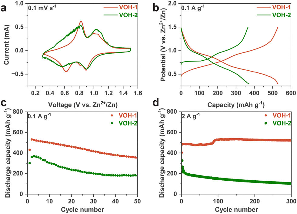 | ||
| Fig. 4 The electrochemical characterization of VOH-1 and VOH-2. (a) The CV curves of the first cycles. (b) The capacity–potential curves of the second cycles. (c) and (d) The cycling performance. | ||
This work demonstrates the importance of electrolyte environment during in situ self-transformation for synthesizing V2O5·nH2O. 2 M ZnSO4 leads to a tendency to grow along the electric field and alters the crystal growth orientation. This causes expanded volume, porous surface morphology and low crystallinity along the (0 0 1) plane and results in excellent cycling performance. 2 M Zn(OTf)2 leads to a volume reduction, making the electrolyte difficult to infiltrate. The importance has been proved by contrasting the production of different electrolytes. This work expands the possibility for in situ self-transformation.
Conflicts of interest
There are no conflicts to declare.Notes and references
- S. Liu, L. Kang, J. M. Kim, Y. T. Chun, J. Zhang and S. C. Jun, Adv. Energy Mater., 2020, 10, 2000477 CrossRef CAS.
- F. Ming, H. Liang, Y. Lei, S. Kandambeth, M. Eddaoudi and H. N. Alshareef, ACS Energy Lett., 2018, 3, 2602–2609 CrossRef CAS.
- J. Zhou, L. Shan, Z. Wu, X. Guo, G. Fang and S. Liang, Chem. Commun., 2018, 54, 4457–4460 RSC.
- S. Deng, Z. Yuan, Z. Tie, C. Wang, L. Song and Z. Niu, Angew. Chem., Int. Ed., 2020, 59, 22002–22006 CrossRef CAS PubMed.
- H. Jiang, W. Gong, Y. Zhang, X. Liu, M. Waqar, J. Sun, Y. Liu, X. Dong, C. Meng, Z. Pan and J. Wang, J. Energy Chem., 2022, 70, 52–58 CrossRef CAS.
- S. Liu, H. Zhu, B. Zhang, G. Li, H. Zhu, Y. Ren, H. Geng, Y. Yang, Q. Liu and C. C. Li, Adv. Mater., 2020, 32, 2001113 CrossRef CAS PubMed.
- M. Yan, P. He, Y. Chen, S. Wang, Q. Wei, K. Zhao, X. Xu, Q. An, Y. Shuang, Y. Shao, K. T. Mueller, L. Mai, J. Liu and J. Yang, Adv. Mater., 2018, 30, 1703725 CrossRef PubMed.
- J. Shin, D. S. Choi, H. J. Lee, Y. Jung and J. W. Choi, Adv. Energy Mater., 2019, 9, 1900083 CrossRef.
- M. Tian, C. Liu, J. Zheng, X. Jia, E. P. Jahrman, G. T. Seidler, D. Long, M. Atif, M. Alsalhi and G. Cao, Energy Storage Mater., 2020, 29, 9–16 CrossRef.
- C. Xia, J. Guo, P. Li, X. Zhang and H. N. Alshareef, Angew. Chem., Int. Ed., 2018, 57, 3943–3948 CrossRef CAS PubMed.
- Y. Zhang, T. Cheng, Y. Wang, W. Lai, H. Pang and W. Huang, Adv. Mater., 2016, 28, 5242–5248 CrossRef CAS.
- G. Yilmaz, K. M. Yam, C. Zhang, H. J. Fan and G. W. Ho, Adv. Mater., 2017, 29, 1606814 CrossRef PubMed.
- D. Ma, Y. Li, H. Mi, S. Luo, P. Zhang, Z. Lin, J. Li and H. Zhang, Angew. Chem., 2018, 130, 9039–9043 CrossRef.
- D. Ma, Y. Li, J. Yang, H. Mi, S. Luo, L. Deng, C. Yan, M. Rauf, P. Zhang, X. Sun, X. Ren, J. Li and H. Zhang, Adv. Funct. Mater., 2018, 28, 1705537 CrossRef.
- Y. Zhang, M. Fan, X. Liu, G. Xie, H. Li and C. Huang, Solid State Commun., 2012, 152, 253–256 CrossRef CAS.
- J. Chen, B. Xiao, C. Hu, H. Chen, J. Huang, D. Yan and S. Peng, ACS Appl. Mater. Interfaces, 2022, 14, 28760–28768 CrossRef CAS PubMed.
- J. Wang, X. Zhang, Y. Zhang, A. Abas, X. Zhao, Z. Yang, Q. Su, W. Lan and E. Xie, RSC Adv., 2017, 7, 35558–35564 RSC.
- J.-S. Park, J. H. Jo, Y. Aniskevich, A. Bakavets, G. Ragoisha, E. Streltsov, J. Kim and S.-T. Myung, Chem. Mater., 2018, 30, 6777–6787 CrossRef CAS.
- L. Wang, K.-W. Huang, J. Chen and J. Zheng, Sci. Adv., 2019, 5, eaax4279 CrossRef CAS PubMed.
- H. Luo, B. Wang, F. Wu, J. Jian, K. Yang, F. Jin, B. Cong, Y. Ning, Y. Zhou, D. Wang, H. Liu and S. Dou, Nano Energy, 2021, 81, 105601 CrossRef CAS.
- Q. Zong, Y. Zhuang, C. Liu, Q. Kang, Y. Wu, J. Zhang, J. Wang, D. Tao, Q. Zhang and G. Cao, Adv. Energy Mater., 2023, 13, 2301480 CrossRef CAS.
- Y. Kim, Y. Park, M. Kim, J. Lee, K. J. Kim and J. W. Choi, Nat. Commun., 2022, 13, 2371 CrossRef CAS PubMed.
Footnote |
| † Electronic supplementary information (ESI) available. See DOI: https://doi.org/10.1039/d3cc05902b |
| This journal is © The Royal Society of Chemistry 2024 |