
 Open Access Article
 This Open Access Article is licensed under a
 Creative Commons Attribution 3.0 Unported Licence
HunStat – a simple and low-cost potentiostat for analytical and educational purposes†
Istvan
Vamos
a and
Vilmos
Kertesz
 *b
*b
aLajos Petrik Vocational Chemistry School, Budapest, Hungary
bBiosciences Division, Oak Ridge National Laboratory, USA. E-mail: kerteszv@ornl.gov
First published on 24th May 2024
Abstract
We have developed a truly low-cost (15 USD), simple do-it-yourself (DIY) potentiostat with compact dimensions. The output potential range of this device is between ±1.65 V. The developed instrument takes advantage of a Seeeduino XIAO microcontroller equipped with 10 bit digital-to-analog (D/A) and 12 bit analog-to-digital (A/D) converters and supports various voltammetry techniques, including cyclic voltammetry (CV), differential pulse voltammetry (DPV), and chronoamperometry (CA). Interested users are provided with circuit diagrams, bill of materials, and design files. Additionally, software components are also provided free of charge, including an Arduino sketch and control software. The software enables easy manipulation of electrochemical parameters and visualization of results. The presented design introduces a simple and low-cost DIY potentiostat recommended for both analytical and educational purposes.
1 Introduction
Potentiostats are electrochemical instruments facilitating the investigation of redox reactions that enable researchers to understand reaction mechanisms and kinetics in electrochemical systems.1 Unfortunately, potentiostats are costly in general (about $500 and up). Beside these research-grade instruments, low-cost variants enable electrochemical experimentation accessible to a broader audience, including educators, and researchers with limited budgets. By reducing the barrier to entry, more individuals can engage in electrochemical research and education.Numerous “do-it-yourself” (DIY) potentiostats have already been published.2–15 Particularly, Arduino-based16 potentiostats4,7,11,15 have gained significant popularity due to their easily manageable microcontroller integration. Arduinos not only incorporate a microcontroller but also include an analog-to-digital (A/D) converter, with digital-to-analog (D/A) conversion achieved through pulse width modulation (PWM). In Table 1, we summarize the key characteristics of low-cost potentiostats published since 2011.
| Name | Year | Range V | Microcontroller | Price USD | ADC resolution bit and (mV) | DAC resolution bit and mV | Techniques | GUI | Ref. |
|---|---|---|---|---|---|---|---|---|---|
| a If a potentiostat was not named, we assigned the name of the chief architect. | |||||||||
| CheapStat | 2011 | ±0.99 | ATxmega32A4 | 100 | 12 (0.5) | 10 (2) | CV, LSV, SWV | Java | 2 |
| OliView | 2014 | ±1 | Teensy 3.1 | 100 | 10 (2) | 12 (0.5) | CV, ASV, CA | Qt creator | 3 |
| Melonia | 2016 | ±1 | Arduino UNO | 20 | 10 (2) | 8 (8) | CV | None | 4 |
| DStat | 2017 | ±1.5 | ATmega256 | 130 | 24 (0.0002) | 16 (0.046) | CV, LSV, SWV, DPV | Python-based | 5 |
| Dobbelearea | 2017 | ±8 | PIC16F1459 | 100 | 22 (0.004) | 20 (0.015) | CV, charge/discharge | Python-based | 6 |
| JUAMI | 2018 | ±2.5 | Arduino UNO | 40 | 10 (5) | 8 (20) | CV, LSV, CA | LabVIEW | 7 |
| PSoC-stat | 2018 | ±2 | CY8CKIT-59 | 20 | 12 (0.1) | 12 (0.1) | CV, CA, ASV | Python-based | 8 |
| SimpleStat | 2019 | ±0.99 | Attiny412 | 10 | 10 (2) | 8 (8) | CV, SWV, CA | Python-based | 9 |
| KickStat | 2020 | ±0.79 | SAMD21/LMP91000 | 20 | 12 (0.4) | 10(1.6) | CV, SWV, NPV, CA | None | 10 |
| Paqari stat | 2021 | ±1.5 | Arduino nano | 25 | 8 (12) | 8(12) | CV, CA, DPV, SWV | Mobil app | 11 |
| MYSTAT | 2021 | ±12 | PIC16F1459 | 230 | 22 (0.006) | 20 (0.02) | CV, CA, SWV, OCP | Python-based | 12 |
| PassStat | 2022 | ±2.5 | Teensy 3.6 | 75 | 10 (4.8) | 12 (1.2) | CV, SWV | Python-based | 13 |
| NanoStat | 2022 | ±0.6 | ESP32/LMP91000 | 90 | 12 (0.3) | 8 (4.7) | CV, NPV, SWV, CA | HTML5/Java | 14 |
| PolArStat | 2023 | ±3.3 | Arduino UNO | 45 | 16 (0.1) | 12 (1.6) | CV, CA | Python-based | 15 |
| HunStat | 2024 | ±1.65 | Seeeduino XIAO | 15 | 12 (0.8) | 10 (3.3) | CV, LSV, DPV, CA | Standalone | |
We have built and tested,3,4,6–9,13,15 or obtained and tested2,14 several of the potentiostats shown in Table 1 and we evaluated them in an educational environment. For students, undergraduates, and their instructors lacking experience in electronics and information technology, constructing more complex circuits or installing their software can pose difficulties. In addition, the graphical user interfaces (GUIs) and data analysis of some of the easily constructible potentiostats typically involve sometimes expensive, and often relatively large software tools (LabVIEW, Qt Creator, PyQtGraph, etc.).2,3,7,14
The aim of our work was to develop a low-cost potentiostat featuring a genuine (10 bit) D/A converter for precise voltage output. In addition, a potential range of at least ±1.5 V was a requirement to allow the full range of analysis of aqueous electrolytes. Furthermore, easy construction not requiring prior specialized knowledge and an easy-to-use software interface not requiring any installation were also our goals.
In this paper, we report on the development of the hardware of the HunStat device controlled by a Seeeduino XIAO microcontroller.17 We present simple Windows-based freeware software to operate this device. We have also shown comparative measurements with a commercially available potentiostat, and the results from several electrochemical measurements performed with the HunStat system.
2 Materials and methods
2.1 Chemicals and reagents
Milli-Q Waterwater with an electrical resistivity of > 18.2 MΩ cm was used in all experiments. KNO3, K4Fe(CN)6, CdNO3, PbNO3, HgCl2, FeCl3, AgNO3, NaCl, tartaric acid, cc. HCl, 96% acetic acid solution, 25% NH4OH solution and ascorbic acid were obtained from Sigma-Aldrich Kft. (Budapest, Hungary). A pH = 4.6 ammonium acetate buffer solution was prepared by mixing 56 mL of 96% acetic acid and 37 mL of 25% NH4OH solution, and diluted to a final volume of 1 L with water. Caution! CdNO3, PbNO3 and HgCl2 are extremely poisonous. Work with rubber gloves and do not pour the remaining solution down the drain. Keep the finished Hg electrode in deionized water (to prevent evaporation of Hg). Always read the MSDS of all used chemicals before using them and follow the federal and local regulations.2.2 Hardware
The Seeeduino XIAO development board and the various circuit elements (operational amplifier, resistors and capacitors) were purchased from Mouser Electronics (Mansfield, TX, USA) to build the HunStat potentiostat. Part numbers and prices (as of April 16, 2024) can be found in Table 2. Silicon (type 1N4151) and germanium (type OA1140) diodes, and a USB C cable were purchased in a local electronics store for ∼$2. 10 pieces (lowest quantity to be ordered, ∼$10 total) of the printed circuit board (PCB) were ordered from a local PCB manufacturer.| Quantity | Component | Value | Price, $ | Mouser part number |
|---|---|---|---|---|
| a *USB C cable was purchased locally for ∼$2. **10 pieces of PCB were purchased for ∼$10 ($1 per piece). ***10 pieces of 90 degree 3-pin connector to connect the SPE electrode to the board were purchased for ∼$1 (0.1$-per piece). | ||||
| 1 | AD8648ARZ op. Amp. | (SOIC) | 3.29 | 584-AD8648ARZ |
| 1 | Seeeduino XIAO | 5.40 | 713-102010328 | |
| 5 | 1206 SMD resistor | 10 K (1%) | 1.45 | 71-RCC120610K0FKEA |
| 2 | Resistor 1206 SMD | 510 (5%) | 0.28 | 71-CRCW1206510RJNEB |
| 1 | Capacitor 1206 SMD | 100 nF (50 V) | 0.45 | 77-VJ1206Y104JXAAT |
| 2 | Capacitor 1206 SMD | 10 μF (25 V) | 0.36 | 187-CL31A106KAHNNNF |
Every potentiostat incorporates operational amplifiers depicted in a basic design in Fig. S1.†,1 The HunStat potentiostat was built by the same principles. The schematic diagram, printed circuit boards, the soldered final design of the HunStat potentiostat and the photo of the developed potentiostat connected with the computer and the GUI of the system during an experiment are shown in Fig. 1. The components required for assembling this potentiostat are listed in Table 2. Detailed description of the diagram and details on the potentiostat hardware are described in the ESI section.†
 | ||
| Fig. 1 (a) Schematic diagram, and Gerber file of the (b) front and (c) back of the double-sided PCB, (d) the front of the manufactured PCB, (e) the assembled HunStat potentiostat and (f) photo of the developed potentiostat connected with the computer and the GUI of the system during an experiment. | ||
2.3 Software
After building the hardware, the next step is installing the operational software. To do this, the Arduino IDE software should be installed on the computer.16 Next, the Arduino sketch (PoteVK-3.2. ino)18,19 needs to be uploaded on the Seeeduino. Finally, Windows graphical user interface (GUI) software and associated parameter files (HunStat.exe and HunStat.ini, respectively) are installed for the potentiostat.18,19 Note, these files might go through changes as we might extend the available electrochemical techniques. Contact the authors for the latest version of the software components. More details about Seeeduino XIAO sketch upload can be found on the Seeeduino website.17 After connecting the potentiostat and launching the GUI, the initial screen appears (Fig. S4†). Detailed description of the software interface can be found in the ESI section.†2.4 Electrodes
Except the anodic stripping voltammetry (ASV) measurement for heavy metals described in Section 3.4, all experiments described below were conducted using a carbon screen-printed electrode (SPE, model DS110, Fig. S6†) purchased from DropSens (Llanera, Spain). The electrode was connected to the board using a 90 degree 3-pin connector (part no: DS1020-03RT1D, Connfly, China) purchased from a local electronic store at about $1 per 10 pieces. The three pins of the connector were soldered to the electrical connections of three electrodes on the board.The ASV experiment utilized a home-made 3-electrode layout. First, a layout made of Cu on a PCB board (shown in Fig. S7a†) is created using a general etching technique using FeCl3. The central circular spot was used as the working electrode (WE), the right semicircular arc was used as the counter electrode (CE), and the left short connector was used as the reference electrode (RE). By dropping a saturated HgCl2 solution on the WE and the CE, the surface of the Cu plate is coated with Hg. It is advisable to perform this operation immediately before the measurement, because the thin Hg film diffuses into the Cu bulk. After removing the HgCl2 solution by rinsing, a shiny Hg film can be obtained if the given surface of the plate is thoroughly rubbed with a paper towel. VERY IMPORTANT: Please read the 2.1 Chemicals and reagents section on how to handle Hg and HgCl2. The reference electrode is made with silver plating. To make the RE, a silvering paste was prepared by mixing 1 g AgNO3, 3 g NaCl and 6.5 g tartaric acid thoroughly and wetted with 1 g of water. The paste was then applied to the Cu surface of the left short connector. After letting it stand for a few minutes, a well-adherent Ag layer appeared on the Cu surface and was used as the RE. The surface of the Cu which should be protected from modification can be coated with a layer of varnish or paint. A finished electrode system is shown in Fig. S7b.†
Alternatively, the commercial DS110 SPE can be modified to be a Hg electrode as well. For this, a Hg film is created on the carbon working electrode by preparing a 20 mg L−1 HgCl2 solution slightly acidified with 0.1 M HCl. While stirring, the carbon SPE electrode is immersed in the solution and −1.0 V is applied to the WE for 5 min. As a result, a thin Hg film is formed on the carbon electrode. The HgCl2 solution can be used several times.
3 Results and discussion
3.1 Validation of the HunStat potentiostat
To validate the HunStat system, comparative cyclic voltammetry (CV) measurements were conducted using the HunStat and a commercially available 910 PSTAT mini potentiostat (Metrohm, Riverview, FL, USA). First, a 10 kΩ dummy cell (RE and CE connected directly (RE-CE), 10 kΩ resistor between RE-CE and WE) was analyzed. (Note, there is no solution needed.) The overlapping CV curves in Fig. 2a validated the proper operation of the HunStat system. | ||
| Fig. 2 Voltammograms of (red lines) HunStat and (black lines) 910 PSTAT mini from Metrohm potentiostats recorded under the same conditions on (a) a 10 kΩ dummy cell (0 to 1 V with 0.1 V s−1) and (b) a 2.5 mM K4Fe(CN)6 in a 0.1 M KNO3 solution (0.2 to 0.4 V with 0.05 V s−1). | ||
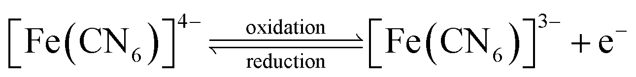
In a follow-up experiment, cyclic voltammograms of a 2.5 mM K4Fe(CN)6 solution were recorded using a SPE. This system was selected as the most commonly used electrochemical measurement for demonstration is the reversible electrochemical behaviour of the K3Fe(CN)6/K4Fe(CN)6 system:
 | (1) |
The obtained CV curves are shown in Fig. 2b. The data collected from the two instruments exhibited remarkable consistency, nearly overlapping throughout the experiments with differences inside measurement reproducibility, again validating the home-made potentiostat.
3.2 Example 1: recording the characteristics of Ge and Si diodes using linear sweep voltammetry (LSV)
LSV is the method of choice for recording diode characteristics. A silicon (type 1N4151) or a germanium (type OA1140) diode was connected between the WE and connected CE-RE and the potential was then changed from −0.2 V to the positive direction with a scan rate of 0.1 V s−1. (Note, there is no solution needed.) LSV curves are shown in Fig. 3. It can be clearly seen that the voltage in the opening direction of the Ge diode was much lower than that of the Si one and followed the expected behavior of these diodes.20 | ||
| Fig. 3 Linear sweep voltammograms of (black line) Si (type 1N4151) and (red line) Ge (type OA1140) diodes. Start potential was −0.2 V for both, and end potentials were 0.2 V and 0.55 V for Ge and Si diodes, respectively. The WE was equilibrated at −0.2 V for 1 s before recording a voltammogram. Scan rate was 0.1 V s−1. | ||
3.3 Example 2: scan rate dependence of cyclic voltammetry using a K4Fe(CN)6 solution
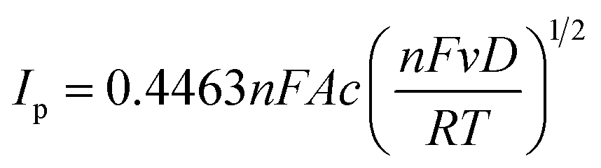
Cyclic voltammetry is a powerful and popular electrochemical technique commonly employed to investigate the reduction and oxidation processes of molecular species. In this set of experiments, CV was employed to study the scan rate dependence of the reversible electrochemical system shown in eqn (1).A 5 mM solution of K4Fe(CN)6 in a 0.1 M KNO3 supporting electrolyte solution was prepared and cyclic voltammograms between −0.2 V and 0.6 V were recorded using scan rates of 0.04, 0.06, 0.08 and 0.1 V s−1 (Fig. 4a). Anodic and cathodic peak currents were calculated and their ratio in all four cases was in 5% proximity of 1 indicating a fully reversible reaction (not shown). Furthermore, the observed peak current on the forward potential scan is given for the case of diffusion-controlled electron transfer by the Randles–Sevcik equation:1
 | (2) |
 | ||
| Fig. 4 (a) Cyclic voltammograms of 5 mM K4Fe(CN)6 in a 0.1 M KNO3 solution recorded between −0.2 V and +0.6 V using scan rates of (solid red line) 0.04 V s−1, (solid black line) 0.06 V s−1, (dashed black line) 0.08 V s−1 and (dash-dot black line) 0.1 V s−1. (b) Peak current (Ip) as the function of the square root of scan rate. The linear fit resulted in: Ip (μA) = 7.393 × 10²v1/2 (V s−1)1/2 + 8.581 × 101, R2 = 0.9987. | ||
Eqn (2) shows that peak current linearly changes as a function of the square root of the scan rate for a diffusion-controlled electron transfer reaction. Plot of Ip as a function of ν1/2 is presented in Fig. 4b and shows a good linearity (Ip (μA) = 7.393 × 10²v1/2 (V s−1)1/2 + 8.581 × 101, R2 = 0.9987) supporting the diffusion-controlled nature of the reaction described in eqn (1).
3.4 Example 3: anodic stripping voltammetry (ASV) of cadmium and lead using potentiostatic enrichment and differential pulse voltammetry (DPV)
Anodic stripping voltammetry is particularly employed for the determination of heavy metals. During enrichment, the metal ions are deposited onto the electrode at a negative potential on Hg, and from the formed amalgam, the metal is stripped back by reversing the electrode potential in the positive (anodic) direction. The metals are oxidized, resulting in an anodic current that is linearly proportional to the metal content.To make samples, a CdNO3 + PbNO3 standard stock solution (10 mg L−1, i.e. 10 ppm for both heavy metals) was prepared. 500 μL of the standard stock solution was then added to 10 mL of 1 M HCl solution (20x dilution). The SPE electrode equipped with a Hg film was immersed into this solution and, while stirring, Cd and Pb were enriched in the Hg film for 1 min at a deposition potential of −1.1 V via reduction of the corresponding heavy metal ions:
| Cd2+/Pb2+ + Hg + 2e− → Cd0(Hg)/Pb0(Hg) | (3) |
After 1 min expired, a DPV was collected between −1.0 V and −0.4 V (Fig. 5a, solid red line) while the heavy metals in the amalgam were oxidized into their ionic forms:
| Cd0(Hg)/Pb0(Hg) → Cd2+/Pb2+ + Hg + 2e− | (4) |
 | ||
| Fig. 5 (a) Differential pulse voltammograms of the (solid red line) original 10 ppm CdNO3/PbNO3 solution and when the original 10 mL solution was spiked with a total of (solid black line) 500 μL, (dotted black line) 1000 μL and (dashed black line) 1500 μL of 10 ppm CdNO3/PbNO3 solution. Preconcentration using a Hg electrode at −1.1 V was accomplished for 1 min. DPV start and end potentials were −1.0 V and 0.4 V, respectively. Potential step was 3 mV with a pulse amplitude, period and width of 50 mV, 100 ms and 50 ms, respectively. Sampling period was 3 ms. (b) Standard addition curves for (b) PbNO3 and (c) CdNO3 solutions. Equations for linear fits of anodic peak currents: Ip,Pb (μA) = 20.11 × cPb,added (ppm) + 9.77; Ip,Cd (μA) = 22.17 × cCd,added (ppm) + 10.93. | ||
500 μL standard was added three times to the original solution (equivalent to 0.5 ppm increase in each step) and the DPVs were recorded with the same parameters (enrichment + dissolution). Fig. 5a shows all four DPV curves. Standard addition curves using the concentration increments and anodic peak currents for PbNO3 and CdNO3 are shown in Fig. 5b and c, respectively. Fitting the anodic peak current values in these figures resulted in Ip,Pb (μA) = 20.11 × cPb,added (ppm) + 9.77; Ip,Cd (μA) = 22.17 × cCd,added (ppm) + 10.93, respectively. From these equations the x-intercepts for Pb2+ and Cd2+ were −0.486 and −0.493 ppm from which the original (i.e. before the 20x dilution) Pb2+ and Cd2+ concentrations were calculated to be 9.72 and 9.86 ppm, respectively. These numbers showed acceptable agreement with the expected 10 ppm values.
3.5 Example 4: concentration measurement of ascorbic acid using chronoamperometry (CA)
In chronoamperometry, a potential step is applied on the working electrode and the current is then measured as a function of time.1 Beside studying kinetics of electrochemical reactions, this method can be used for concentration measurement of electroactive compounds. Without convection, the diffusion of an analyte from the bulk solution toward the electrode surface determines the current. In the case of linear diffusion on a planar electrode the current is described by the Cottrell equation: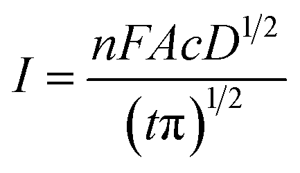 | (5) |
Solutions of 1, 2, 2.5, 3, 4, and 5 mM ascorbic acid in a 1![[thin space (1/6-em)]](https://www.rsc.org/images/entities/char_2009.gif) :20 diluted ammonium acetate buffer supporting electrolyte solution were prepared. CA curves were recorded for t = 11 s after the working electrode potential was stepped from open circuit potential to 0.8 V at t = 1.2 s (Fig. 6a). The measured current at t = 10 s (It=10 s) is then plotted in Fig. 6b for each concentration. A calibration curve was created using a linear fit and these currents for 1, 2, 3, 4, and 5 mM ascorbic acid solutions (It=10 s(μA) = 5.865 × cascorbic acid (mM) + 4.06. R2 = 0.995). Using this linear fit and the current value obtained using the 2.5 mM ascorbic acid solution (18.611 μA, red filled circle in Fig. 6b), the calculated concentration was 2.48 mM that represents a <1% error showing the power of this method.
:20 diluted ammonium acetate buffer supporting electrolyte solution were prepared. CA curves were recorded for t = 11 s after the working electrode potential was stepped from open circuit potential to 0.8 V at t = 1.2 s (Fig. 6a). The measured current at t = 10 s (It=10 s) is then plotted in Fig. 6b for each concentration. A calibration curve was created using a linear fit and these currents for 1, 2, 3, 4, and 5 mM ascorbic acid solutions (It=10 s(μA) = 5.865 × cascorbic acid (mM) + 4.06. R2 = 0.995). Using this linear fit and the current value obtained using the 2.5 mM ascorbic acid solution (18.611 μA, red filled circle in Fig. 6b), the calculated concentration was 2.48 mM that represents a <1% error showing the power of this method.
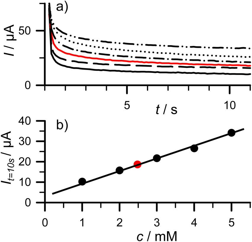 | ||
| Fig. 6 (a) Chronoamperometric measurement of calibration solutions (solid black line) 1 mM, (dashed black line) 2 mM, (dash-dot black line) 3 mM, (dotted black line) 4 mM, (dash-dot-dot black line) 5 mM, and quality control solution (solid red line) 2.5 mM ascorbic acid in 1:20 diluted ammonium acetate buffer. (b) Current recorded at t = 10 s (It=10 s) as a function of ascorbic acid concentration. Equation for linear fit: It=10 s (μA) = 5.865 × cascorbic acid (mM) + 4.06. R2 = 0.995. | ||
4 Conclusion
We have developed an easy to build, low-cost, Arduino clone based potentiostat (HunStat) suitable for analytical and educational applications. The supported techniques include CV, LSV, DPV, and CA. We used a special Arduino clone (Seeeduino XIAO) employing a 12 bit A/D resolution and a genuine 10 bit D/A converter that supports a ±1.65 V/±165 μA measurement range with appropriate resolution and accuracy. Further advantages over former potentiostats include low cost (i.e., ∼15 USD total) and simplicity to build. Assembly and soldering can be finished within 1 hour after procuring the PCB and components. Although the components are surface mount devices (SMDs), the size 1206 parts can be easily soldered manually using tweezers and the finished potentiostat can be directly connected to the PC using a C-type USB cable.The simple-to-use GUI software boasts several features: real-time potential–current curve plotting, baseline editing, peak height evaluation, curve smoothing, and the option to export measurement data series. In addition, the GUI is a standalone, single Windows executable file, not requiring any installation and smaller than 1 MB in size.
We believe that beside research laboratories, the HunStat potentiostat is also suitable for middle and upper-level educational purposes. The experimental descriptions demonstrate that reproducible and sufficiently accurate voltammetric measurements can be carried out with this device.
Our future plans include creating and publishing PBCA files of the Gerber export that would allow users to order fully assembled PCBs instead of having to hand-solder SMD components by themselves. In addition, adding headers and pins to mount the Seeeduino XIAO to the PCB would avoid soldering and thus it would make production easier. Beside these developments of the current potentiostat, creating a similarly straightforward device suitable for electrochemical impedance spectroscopy (EIS) measurements is also included in our future plans.
5 Hazards and safety precautions
CAUTION! Mercuric chloride, lead and cadmium nitrates are poisonous! Work with rubber gloves and do not pour the remaining solution down the drain! Keep the finished mercury electrode in deionized water (to prevent evaporation of mercury). Always read the MSDS of all used chemicals before using them and follow the federal and local regulations.Author contributions
Istvan Vamos: conceptualisation, methodology; investigation; formal analysis; writing – original draft. Vilmos Kertesz: project administration; software; visualization; writing – review & editing.Conflicts of interest
The authors report no conflict of interest.Acknowledgements
The work of VK was sponsored by Oak Ridge National Laboratory, managed by UT-Battelle, LLC, for the U. S. Department of Energy. This manuscript has been authored by UT-Battelle, LLC, under contract DE-AC05-00OR22725 with the US Department of Energy (DOE). The publisher, by accepting the article for publication, acknowledges that the US government retains a nonexclusive, paid-up, irrevocable, worldwide license to publish or reproduce the published form of this manuscript, or allow others to do so, for US government purposes. DOE will provide public access to these results of federally sponsored research in accordance with the DOE Public Access Plan (https://www.energy.gov/downloads/doe-public-access-plan).Notes and references
- A. J. Bard and L. R. Faulkner, Electrochemical Methods: Fundamentals and Applications,Wiley, New York, USA, 2001 Search PubMed.
- A. A. Rowe, A. J. Bonham, R. J. White, M. P. Zimmer, R. J. Yadgar, T. M. Hobza, J. W. Honea, I. Ben-Yaacov and K. W. Plaxco, PLoS One, 2011, 6(9), e23783, DOI:10.1371/journal.pone.0023783.
- https://2014.igem.org/Team:UC_Davis/Potentiostat_Design_Inspiration_Iteration, last accessed on April 22, 2024.
- G. N. Meloni, J. Chem. Educ., 2016, 93, 1320–1322, DOI:10.1021/acs.jchemed.5b00961.
- M. D. M. Dryden and A. R. Wheeler, PLoS One, 2015, 10(10), e0140349, DOI:10.1371/journal.pone.0140349.
- T. Dobbelaere, P. M. Vereecken and C. Detavernier, HardwareX, 2017, 2, 34–49, DOI:10.1016/j.ohx.2017.08.001.
- Y. C. Li, E. L. Melenbrink, G. J. Cordonier, C. Boggs, A. Khan, M. K. Isaac, L. K. Nkhonjera, D. Bahati, S. J. Billinge, S. M. Haile, R. A. Kreuter, R. M. Crable and T. E. Mallouk, J. Chem. Educ., 2018, 95, 1658–1661, DOI:10.1021/acs.jchemed.8b00340.
- P. Lopin and K. V. Lopin, PLoS One, 2018, 13(7), e0201353, DOI:10.1371/journal.pone.0201353.
- A. Butterworth, D. Corrigan and A. C. Ward, Anal. Methods, 2019, 11(14), 1958–1965, 10.1039/C9AY00383E.
- O. S. Hoilett, J. F. Walker, B. M. Balash, N. J. Jaras, S. Boppana and J. C. Linnes, Sensors, 2020, 20(8), 2407, DOI:10.3390/s20082407.
- A. V. Cordova-Huaman, V. R. Jauja-Ccana and A. La Rosa-Toro, Heliyon, 2021, 7(2), e06259, DOI:10.1016/j.heliyon.2021.e06259.
- P. Irving, R. Cecil and M. Z. Yates, HardwareX, 2021, 9, e00163, DOI:10.1016/j.ohx.2020.e00163.
- M. Caux, A. Achit, K. Var, G. Boitel-Aullen, D. Rose, A. Aubouy, S. Argentieri, R. Campagnolo and E. Maisonhaute, HardwareX, 2022, 11, e00290, DOI:10.1016/j.ohx.2022.e00290.
- S. C.-H. Lee and P. J. Burke, Electrochim. Acta, 2021, 422, 140481, DOI:10.1016/j.electacta.2022.140481.
- T. Ticher, M. Gernhard and P. C. K. Vesborg, Electrochim. Acta, 2023, 469, 143119, DOI:10.2139/ssrn.4341560.
- https://www.arduino.cc/, last accessed on April 22, 2024.
- https://wiki.seeedstudio.com/Seeeduino-XIAO/, last accessed on April 22, 2024.
- https://u.pcloud.link/publink/show?code=kZWi9Q0ZDKDqVdhYM6LeM8N1iLdgRSNH0pzy, last accessed on April 22, 2024.
- https://www.osti.gov/doecode/biblio/105058, last accessed on April 22, 2024.
- https://learn.sparkfun.com/tutorials/diodes/real-diode-characteristics, last accessed on April 22, 2024.
Footnote |
| † Electronic supplementary information (ESI) available: Details included on the potentiostat hardware, setting up Seeeduino XIAO in the Arduino IDE and information on the HunStat graphical user interface software. See DOI: https://doi.org/10.1039/d4ay00791c |
| This journal is © The Royal Society of Chemistry 2024 |