
 Open Access Article
 This Open Access Article is licensed under a
 Creative Commons Attribution 3.0 Unported Licence
A comprehensive review of cathode materials for Na–air batteries
Pengcheng
Mao
a,
Hamidreza
Arandiyan
 *bc,
Sajjad S.
Mofarah
d,
Pramod
Koshy
d,
Cristina
Pozo-Gonzalo
e,
Runguo
Zheng
a,
Zhiyuan
Wang
a,
Yuan
Wang
*e,
Suresh K.
Bhargava
c,
Hongyu
Sun
*a,
Zongping
Shao
f and
Yanguo
Liu
*a
*bc,
Sajjad S.
Mofarah
d,
Pramod
Koshy
d,
Cristina
Pozo-Gonzalo
e,
Runguo
Zheng
a,
Zhiyuan
Wang
a,
Yuan
Wang
*e,
Suresh K.
Bhargava
c,
Hongyu
Sun
*a,
Zongping
Shao
f and
Yanguo
Liu
*a
aSchool of Resources and Materials, Northeastern University at Qinhuangdao, Qinhuangdao 066004, P. R. China. E-mail: hyltsun@gmail.com; lyg@neuq.edu.cn
bLaboratory of Advanced Catalysis for Sustainability, School of Chemistry, University of Sydney, Sydney, NSW 2006, Australia. E-mail: hamid.arandiyan@sydney.edu.au
cCentre for Applied Materials and Industrial Chemistry (CAMIC), School of Science, RMIT University, Melbourne, VIC 3000, Australia
dSchool of Materials Science and Engineering, UNSW Sydney, Sydney, NSW 2052, Australia
eInstitute for Frontier Materials, Deakin University, Melbourne, VIC 3125, Australia. E-mail: wang@deakin.edu.au
fWA School of Mines: Minerals, Energy and Chemical Engineering, Curtin University, Perth, WA 6845, Australia
First published on 22nd February 2023
Abstract
In recent years, rechargeable sodium–air batteries have attracted extensive attention and shown rapid development for use in the field of electrochemical energy storage owing to low costs, abundance of the precursor resources, high theoretical specific capacity, and high energy density, all of which have contributed to making them one of the most promising alternatives to lithium-ion batteries. Despite the numerous advantages, Na–air batteries also face certain challenges, such as poor charge–discharge reversibility at the cathode, formation of sodium dendrites at the anode, and low catalytic activity for oxygen reduction/evolution reactions. Thus, designing efficient and stable air cathode materials is significant for the development and practical application of Na–air batteries. Therefore, this paper aims to review the advances related to the development of air cathodes in Na–air batteries in the last decade. Here, research on the secondary Na–air batteries are briefly summarized and divided into two categories based on their electrolyte composition: organic Na–air batteries and hybrid Na–air batteries. The air cathode materials are reviewed and categorised based on the material type into the following: carbon materials, transition metals and metal oxides, noble metals, perovskites and spinel oxides, metal–organic frameworks and their derivatives, pyrochlore oxides, and other cathode materials. Furthermore, work in previous studies applying in situ spectroelectrochemical techniques, including Infrared spectroscopy, electron spin resonance, UV/Vis spectroscopy, and Raman spectroscopy, to develop the structure-performance correlations and redox reaction mechanisms of Na–air batteries are summarised. Finally, the challenges faced by Na–air batteries and the prospect of future work are discussed in the conclusions. This review is thus expected to provide a comprehensive understanding of the trends and issues related to the development of Na–air batteries for practical industrial applications.
 Pengcheng Mao | Pengcheng Mao is currently a Master's student under the supervision of Prof. Yanguo Liu at the Northeastern University. He has been studying the applications of conductive polymer, including metal–organic frameworks, in energy storage and conversion. Meanwhile, he is interested in the influence of interface interaction (homogeneous interface, heterogeneous interface) on ions and electron transport, devoting himself to developing batteries with high energy density and ultra-fast charging ability. |
 Hamidreza Arandiyan | Hamidreza Arandiyan received his PhD from Tsinghua University in 2014. He was awarded a Vice-Chancellor's Research Fellowship from UNSW Sydney in 2015. He was a University of Sydney Senior Fellowship in the School of Chemistry in 2018. Currently, he is a Senior Research Fellow in the Applied Chemistry & Environmental Science at RMIT University, Melbourne, expanding his work on functional battery materials. His research interests lie in heterogeneous catalysis for environmental remediation and energy applications. |
 Sajjad S. Mofarah | Sajjad S. Mofarah obtained his PhD in Materials Science and Engineering, UNSW Sydney, in 2020, with a focus on electrochemistry-based synthesis and characterisation of 2D metal oxides, heterostructures, and coordination polymers for energy storage and catalysis applications. He was appointed as a Research Associate at SMaRT Centre at UNSW in April 2020 to work on cyclic reprocessing of battery materials and recovery of wastes into functional nanostructures for electrocatalysis and capacitance applications. Upon being appointed as Senior Research Associate at the NEMCAT group, UNSW Sydney, and Chief Scientist at Vecor Technologies Pty. Ltd. in 2022, he started working on research and development of cathodic materials for lithium and sodium rechargeable batteries. Among his research interests are fabrication, advanced characterization, and thermodynamic analyses of defective layered oxides and perovskites for energy storage applications. |
 Pramod Koshy | Pramod Koshy received his PhD in Materials Science and Engineering, UNSW Sydney in 2009. He has worked as a researcher in the same organization after that and has received continuous funding from industries and the Australian Research Council. He is currenly employed as an Associate Professor and co-leads the NEMCAT research group at UNSW Sydney. His primary research has focused on the development of materials and technologies in waste resource transformation, nano-biomaterials, and catalytic material development for air and water purification. He has also supervised over 50 higher students and over 90 Honours students to completion. |
 Cristina Pozo-Gonzalo | Cristina Pozo-Gonzalo attained her degree and honours at the University of Zaragoza (Spain). After graduating, she received her PhD degree in Chemistry from the University of Manchester (United Kingdom) under the supervision of Prof. Peter J. Skabara on the electrochemical synthesis of Conducting Polymers. After moving to Australia, she worked with Prof. Alan Bond at Monash University, and in 2012 she joined Deakin University, where she has been working in reversible metal–air batteries with advanced electrolytes, ionic liquids funded by ARC Centre of Excellence for Electromaterials Science (ACES). Her research interests include metal–air batteries ionic liquids, circular economy, conducting polymers, and critical metal extraction and recovery. In her research career, she has published 95 publications, including 4 patents and 3 book chapters, and managed 33 projects as chief investigator. |
 Yuan Wang | Yuan Wang (Helena) received her PhD degree from the School of Chemical Engineering, The University of New South Wales (UNSW) Sydney Australia in 2018. She was appointed as a Research Assistant at the National Research Center for Geoanalysis, Chinese Academy of Geological Science in 2013. She was a Postdoctoral Research Associate in the School of Chemistry, UNSW Sydney and a Research Fellow in the Applied Chemistry & Environmental Science at RMIT University, Melbourne. Current, she is an Alfred Deakin Research Fellow in the Institute for Frontier Materials (IFM) at Deakin University, Melbourne. Her research interests focus on developing and characterising nanoporous materials for metal–air batteries and electrocatalytic applications. |
 Suresh K. Bhargava | Dist. Prof. Suresh Bhargava is a world-renowned interdisciplinary scientist with decades of leadership in academia and industry. With over 600 highly cited publications including 2 books and 16 book chapters, 12 patents (6 transferred to industry) with >23 |
 Hongyu Sun | Hongyu Sun received his PhD degree from the State Key Laboratory of Metastable Materials Science and Technology, Yanshan University in 2010. He then spent 2 years as a Postdoctoral Research Fellow in the Department of Materials Science and Engineering, Tsinghua University under the direction of Prof. Jing Zhu. He then joined the Beijing National Centre for Electron Microscopy, Tsinghua University. In 2015, he moved to the Technical University of Denmark as a Postdoctoral Research Fellow. His research interests include controllable synthesis of nanostructures for applications in energy storage and conversion (lithium/sodium-ion batteries, electrolysis), liquid cell transmission electron microscopy, and microfabrication. |
 Zongping Shao | Zongping Shao is a Professor of Chemical Engineering at Curtin University, Australia and Nanjing Tech University, China. He obtained his PhD from Dalian Institute of Chemical Physics, China in 2000. He worked as a Visiting Scholar at the Institut de Researches sur la Catalyse, CNRS, France and as a Postdoctoral Research Fellow at the California Institute of Technology, USA, from 2000 to 2005. His research interests include solid oxide fuel cells, lithium-ion batteries, supercapacitors, and low-temperature energy-conversion devices. He has been recognised as a Highly Cited Researcher in the Energy section by Elsevier since 2015. He has also been selected as a World Highly Cited Researcher by (Thomson Reuters) Clairvate Analytics for 2014, 2017, 2018, and 2019. |
 Yanguo Liu | Yanguo Liu received his PhD degree in Material Physics and Chemistry from Yanshan University in 2009. He is currently a Professor at Northeastern University. His research interests include functional nanostructures and energy science. He has published over 50 papers in peer-reviewed journals and holds 15 patents on energy storage materials. |
1. Introduction
Shortage of energy supply and increased environmental pollution are major issues currently, posing challenges to the sustainable development of human society.1–4 The development of green and efficient new energy resources, improvement of energy distribution mechanisms, and rectification of energy shortages have become the main global priorities.1,3 Therefore, lithium-ion batteries (LIBs) have been gaining increasing attention due to their excellent stability, high cycle efficiency, and low electrode potential.5–10 However, their low energy (<500 W h kg−1) and power densities have limited their large-scale application (Table 1).11 Even though researchers continue to rationalize the processes to optimize the materials and structures, the limited energy density and safety concerns related to the Li-ion batteries have prevented them from reaching the levels required to meet current energy demands.12 Therefore, it is imperative that 'green' chemical power be developed with high specific energy and energy density in order to replace existing commercial LIBs. Recently, there has been a great deal of interest in metal–air batteries as an energy storage device due to their high theoretical energy density. Metal–air batteries are secondary batteries in which metal serves as the anode. Air or oxygen undergoes a reduction reaction at the cathode to generate current. The most significant benefit of air batteries is that the positive active material is oxygen from the air. This is inexhaustible and does not need to be stored inside the battery, thus providing a high energy density. In the future, this technology may be used as an alternative to lithium-ion batteries since it serves as a power battery with high specific energy.13–18Table 1 compares the characteristics of LIBs, the lithium–air batteries (LABs) , the Na-ion batteries (NIBs) and the Na–air batteries (SABs). It can be clearly seen that the metal–air batteries exhibit higher specific capacity and energy density compared to the metal–ion batteries, which is favorable to promote the industrial application of metal–air batteries.| Battery | Redox reaction | Theoretical capacity/mA h g−1 | Standard potential /V | Overpotential /mV | Energy density/W h kg−1 | Cycling life | Abundance of the component | Price/$T−1 |
|---|---|---|---|---|---|---|---|---|
| Li–ion batteries | Li0.5CoO2 + 0.5Li → LiCoO2 | 150 (LiCoO2) | ∼4.0 | — | ∼500 (LiCoO2) | >500 | Li: 0.017 | 5000 |
| Co: 0.03 | ||||||||
| Li–air batteries | 2Li + O2 → Li2O2 | 1168 (Li2O2) | 2.96 | >1000 | ∼3500 (Li2O2) | ∼500 | Li: 0.017 | 5000 |
| Na–ion batteries | NaV2(PO4)3 + 2Na → Na3V2(PO4)3 | 117.6 (Na3V2(PO4)3) | 3.4 | — | ∼180 (Na3V2(PO4)3) | 3000 | Na: 2.83 | 150 |
| Na–air batteries | Na + O2 → NaO2 | 488 (NaO2) | 2.27 | <200 | ∼1108 (NaO2) | ∼2000 | Na: 2.83 | 150 |
LABs were first reported in 1996 and have attracted widespread attention since then owing to their extremely high specific capacity and outstanding theoretical energy density (3500 W h kg−1).19 However, the high overpotential during the charging/discharging process makes the round-trip efficiency relatively low, resulting in relatively poor reversible performance and cycle stability.20–22 Considering the shortage of metal lithium resources and the similar physical and chemical properties of metal sodium and lithium,22–24 the replacement of metal lithium with metal sodium has become a hot spot in battery research and SABs as a future energy storage device have also attracted the interest of many researchers.25–29 The emergence of SABs is an important step forward in the research on LIBs, LABs and SIBs. Replacing lithium with sodium, which is more abundant on earth, removes a bottleneck in the resource supply chain and results in lower production costs. Using oxygen from air instead of solid redox-active materials significantly increases the battery's specific capacity and energy density. In 2011, Avshalomov et al.30 assembled and operated the sodium–air battery with liquid–sodium anode at 105 °C. The successful operation of the high-temperature Na–air battery shows that it is feasible for this battery to replace the Li–air battery. However, the assembly and operation of high-temperature Na–air batteries are not practical for commercial use. Later, Fu et al.28 developed a novel room-temperature sodium–air battery with an air electrode exhibiting a high specific capacity of 1884 mA h g−1 at a current density of 1/10C. Due to the very high activity of sodium metal, the SABs had to be operated in an organic electrolyte and a dry, pure oxygen environment. During the SAB discharge process, Na+ is released from the sodium metal anode by an oxidation reaction, and Na+ combines with superoxide anion, O2˙−, at the cathode to form the discharge product sodium superoxide (NaO2); the reverse occurs during the subsequent charging process.11,31,32 Based on the discharge product being sodium superoxide (NaO2), the theoretical energy density of SABs is 1108 W h kg−1, which is very attractive in comparison to the limited energy density of LIBs.33 Interestingly, the formation of NaO2 during the discharge process of SABs competes with the precipitation of sodium peroxide (Na2O2).34 Although Na2O2 is thermodynamically stable compared to NaO2, Na2O2 involves a two-electron transfer process, which is kinetically slower compared to the single-electron transfer of NaO2.33,34 Meanwhile, the SABs with NaO2 as the discharge product have a lower overpotential compared to those with Na2O2 as the discharge product, thereby favouring both higher energy efficiency and improved cycle stability.11,35,36 Therefore, to realize long-cycle stability and low overpotential for Na–O2 batteries, it is essential to conduct an in-depth study on the chemical composition of air cathodes and electrolytes in order to reduce the side reactions.
Despite their desirable high energy density, research on SABs is still in its infancy compared to the current state-of-the-art research on sodium-ion batteries. Many scientific issues still need to be addressed before SABs can be applied practically.37,38 These include (i) factors, such as types, physicochemical properties, and microstructures of electrodes, and their effects on the composition and morphology of sodium–air battery discharge products, and (ii) careful selection and design of electrolyte compositions with excellent chemical and electrochemical stability along with appropriate electrochemical windows that prevent superoxide radical formation and associated side reactions and the sudden death of the batteries. In addition, the protection of the sodium anode from trace water in the electrolyte and the suppression of the formation of sodium dendrites also play an important role in ensuring the high performance of sodium–air batteries. This review will comprehensively summarize the research progress with regard to cathode materials for sodium–air batteries. The first part will discuss the basic theory and chemical reaction processes of air battery cathodes, while the next section will summarize the types and designs of air cathodes consisting of different materials, including carbon-based, transition metals and metal oxides, noble metals, chalcogenides and spinels, metal–organic frameworks and their derivatives, and other materials. This will be followed by a summary of the in situ spectroelectrochemical techniques employed in the research on sodium–air batteries, which are beneficial to promote the rapid development of sodium–air batteries. Finally, the strategies to improve the performance of sodium–air batteries and encourage the practical application of these devices are summarized, along with prospects for future development.
2. Metal–air batteries: theory and basic principle
The discharge/charge reaction mechanisms of metal–air batteries differ from that of conventional lithium-ion or sodium-ion batteries in that the energy density depends primarily on the type of discharge products. The cathode of metal–air batteries only provides the location for nucleation and growth of the discharge products during the discharge process. In various metal–air battery systems, the difference in their energy densities depends mainly on the volume and weight of the discharge products and the redox potentials, regardless of the battery structure. Due to the physical and chemical properties of metallic Li and Na, Na–air and Li–air batteries are very similar in terms of reaction mechanisms and battery configurations (Table 1). Taking the organic Li–air batteries as an example, the lithium metal anode is oxidized to lithium ions during the discharge process and the O2 at the cathode diffuses into the porous electrode, dissolves in the electrolyte, and is reduced during discharge. Li2O2 will be produced as the final discharge product and then decomposed during the charging process. This can be explained using the Lewis acid–base theory: Li+ is a hard Lewis acid with small size and low polarizability, while O2− is a soft Lewis base with larger size, so LiO2 is a “soft–hard compound”. This “soft–hard compound” is usually unstable and prone to decomposition, further resulting in formation of O22− from O2− and Li2O2 as the final discharge product. When the battery is charged, this process is reversed. The electrochemical reactions are shown in eqn (1)–(3).| Anode electrode: Li → Li+ + e− | (1) |
| Cathode electrode: 2Li+ + O2 + 2e− → Li2O2 | (2) |
| Overall: 2Li + O2 → Li2O2 (E0 = 2.96 V) | (3) |
The most studied Na–air batteries are organic–electrolyte Na–air batteries and hybrid–electrolyte Na–air batteries, which differ slightly in terms of their structure (Fig. 1a and b). Fig. 1c describes the timeline related to the research and development of Na–air batteries. In the case of the organic electrolyte Na–air battery, the anode is sodium metal. The cathode is a bifunctional catalyst with a porous structure, while the separator is immersed in the organic electrolyte to prevent short-circuiting.39 In early Na–air batteries, carbonate-based electrolytes were used, but the superoxide anion (O2˙−) would nucleophilically attack the C atoms within the CH2 group, resulting in by-products such as sodium carbonate (Na2CO3).28,40 At present, ethers are often chosen as electrolyte solvents, and these include dimethyl ether (DME), diethylene glycol dimethyl ether (DEGDME), and tetraethylene glycol dimethyl ether (TEGDME). Compounds often selected as electrolyte salts include sodium hexafluorophosphate (NaPF6), sodium perchlorate (NaClO4), sodium trifluoromethyl sulfonate (NaSO3CF3), and sodium bis(trifluoromethanesulfonyl)imide (NaTFSI), but the type and concentration of electrolyte salts affects the performance of Na–O2 batteries. Lutz et al.41 showed that the anion in the dimethyl ether solvent had no significant effect on the formation of discharge products. However, PF6− forms a stable solid electrolyte interface (SEI), while the SEI formed by TFSI− gradually increases with the cycling process, increasing the battery impedance. At the same time, increasing the concentration of electrolyte salt will increase the electrolyte viscosity, resulting in a decrease in both oxygen solubility and ionic conductivity, which has a negative impact on the electrochemical performance of the battery.42 The hybrid electrolyte Na–air batteries contain two electrolytes with the anode and cathode being immersed in organic and aqueous electrolytes, respectively. The diaphragm in the middle of the battery is a sodium ion-conductive solid electrolyte membrane which prevents oxygen and moisture diffusion into the negative compartment. This allows only the unidirectional transport of sodium ions to the negative compartment, preventing the anode from suffering unwanted oxidative reactions.43 The main component of the solid electrolyte is Na3Zr2Si2PO12 (NASICON).44,45 The electrolyte in the positive compartment (anode side) is the same as that for the organic Na–O2 battery, while the negative compartment (cathode side) typically has aqueous electrolyte with NaOH as the solute.46 The two energy storage mechanisms are absorption and gas release at the air cathode during charging and discharging, corresponding to the oxygen reduction reaction (ORR) and oxygen evolution reaction (OER), respectively.22,34,47–49
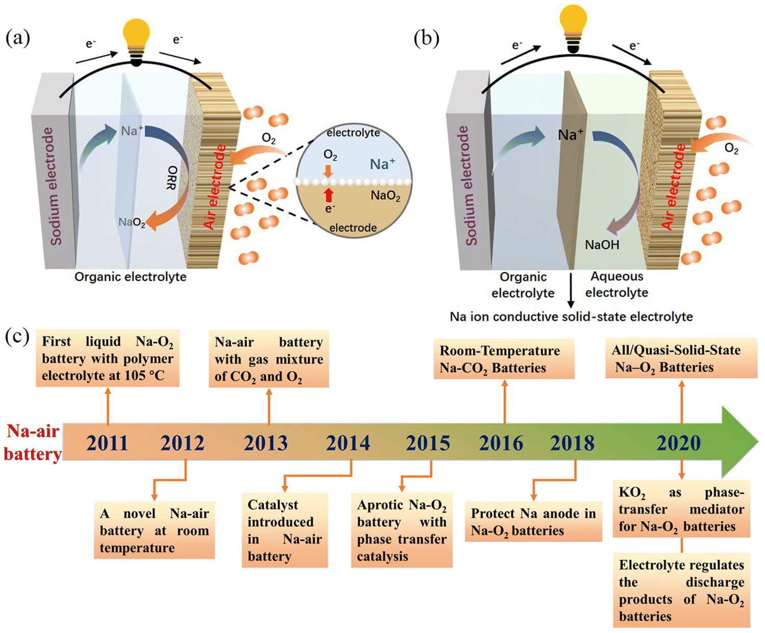 | ||
| Fig. 1 Schematic illustration of the operation of: (a) organic Na–air batteries, and (b) hybrid Na–air batteries, (c) the chronology of major events concerning the development of Na–air batteries in the last decade. | ||
2.1. Organic Na–air batteries
Because of the similarity in chemical properties of metallic Li and Na, organic Na–air batteries share the same reaction mechanism as Li–O2 batteries with regard to energy storage. The Li+ produced during the discharge of Li–O2 batteries is not able to stabilize the highly active O2− and therefore the lithium peroxide formed is the main discharge product of Li–O2 batteries.25 This is because Na+ is softer and has a higher polarizability compared to Li+, which can effectively stabilize O2−. Thus, the main discharge product of Na–O2 battery is NaO2. However, a variety of discharge products have been seen during research under different experimental conditions and these include Na2O2,50,51 Na2O2·2H2O,52 or mixtures,53,54 and their corresponding chemical reactions are shown in eqn (4)–(9):32| Anode: Na → Na+ + e− | (4) |
| Cathode: Na+ + O2 + e− → NaO2 | (5) |
| Overall: Na + O2 → NaO2 (E0 = 2.27 V) | (6) |
| Anode: Na → Na+ + e− | (7) |
| Cathode: 2Na+ + O2 + e− → Na2O2 | (8) |
| Overall: 2Na + O2 → Na2O2 (E0 = 2.33 V) | (9) |
| Cathode | Electrolyte | Current density/mA g−1 | Initial discharge capacity/mA h g−1 | Overpotential/(mV) | Discharge product | Ref. |
|---|---|---|---|---|---|---|
| Carbon thin films | 1 M NaPF6/EC:DMC(1![[thin space (1/6-em)]](https://www.rsc.org/images/entities/char_2009.gif) :1) :1) |
1/10C | 1884 | 1500 | Na2O2 | 28 |
| Carbon nanotube paper | 0.5 M NaSO3CF3/DEGDME | 500 | 7530 | 200 | Na2O2 2H2O | 52 |
| Graphene nanosheets | 0.25 M NaPF6/DME | 300 | 6208 | ∼1600 | Na2O2 | 51 |
| Reduced graphene oxide | 1.0 M NaSO3CF3/DEGDME | 500 | 11935.3 |
∼300 | NaO2 | 14 |
| Porous carbon spheres | 0.5 M NaSO3CF3/DEGDME | 500 | 16500 |
∼400 | NaO2 | 76 |
| Vertically aligned carbon nanotubes | 0.5 M NaSO3CF3/TEGDME | 67 | 4100 | ∼200 | NaO2 | 72 |
| Nitrogen-doped graphene | 0.5 M NaSO3CF3/TEGDME | 75 | 8600 | — | Na2O2 | 50 |
| Graphene aerogel | 0.1 M NaClO4/DME | 100 | 6.61 mA h cm−2 | ∼350 | NaO2 | 77 |
| Nitrogen-doped graphene aerogels | 0.3 M NaSO3CF3/DEGDME | 100 | 10905 |
∼1000 | Na2O2 | 78 |
| Nitrogen-doped carbon | 0.5 M NaSO3CF3/TEGDME | 200 | 5905 | ∼1000 | Na2O2, NaO2 | 79 |
| Nitrogen-doped nanofibers | 0.5 M NaSO3CF3/TEGDME | 100 | 8554.7 | 500 | NaO2 | 11 |
| Nitrogen doped carbon nanotubes on carbon paper | 0.5 M NaSO3CF3/DEGDME | 0.1 mA cm−2 | ∼1350 | — | NaO2 | 71 |
| Nitrogen-doped carbon nanotubes | 0.5 M NaSO3CF3/DEGDME | 25 | 1887 | ∼300 | Na2O2, NaO2 | 54 |
| Boron-doped onion-like carbon | 1.0 M NaSO3CF3/TEGDME | 0.15 mA cm−2 | 10200 |
∼1300 | Na2−xO2 | 75 |
| Reduced graphite oxide | 1.0 M NaSO3CF3/TEGDME | 0.05 mA cm−2 | ∼3.75 mA h cm−2 | ∼1700 | NaO2 | 65 |
| Boron-doped reduced graphite oxide | 1.0 M NaSO3CF3/TEGDME | 0.05 mA cm−2 | ∼3.45 mA h cm−2 | ∼1800 | NaO2 | 65 |
| Ordered mesoporous carbon | 0.5 M NaSO3CF3/PC | 100 | 7987 | ∼1500 | Na2O2, Na2CO3 | 53 |
Two generation mechanisms, known as solution-mediated and surface-mediated, have been proposed to explain the NaO2 crystal formation process for understanding the reaction mechanisms in Na–air batteries. In 2015, Janek et al.58 used theoretical calculations to show that perfect NaO2 crystals are insulating at room temperature with a band gap of 2.0 eV and their lower electronic conductivity (ca. 10−19 S cm−1) was not sufficient for direct electrochemical deposition. They designed a two-electrode device to observe NaO2 dissolution behaviour and observed NaO2 decomposition during charging at an electrode that was not in contact with the fully discharged electrode (Fig. 2a), demonstrating that superoxide dissolution occurs in the electrolyte and providing strong evidence for a solution-precipitation mechanism (Fig. 2b). Subsequently, McCloskey's work59 also showed that precipitation occurs when the dissolved NaO2 reaches its solubility limit, yielding NaO2 crystals of larger size. In 2022, the Ortiz–Vitoriano’ group47 observed that discharge products in graphene nanosheets showed uneven size distribution. At the initial discharge stage, the nucleating molecules are adsorbed on the graphene surface, which facilitates the nucleation of NaO2 through a surface-mediated mechanism. However, as the discharge process progresses, the nucleation sites on the air electrode gradually become saturated, and the NaO2 nucleation mechanism changes from a surface-mediated mechanism to a solution-mediated mechanism, forming larger NaO2 cubes (Fig. 2c). As a result, discharge products have an uneven size distribution. Apart from the solution-mediated and surface-mediated mechanisms described above, there are also solution-mediated mechanisms based on phase transfer agents. As the most common phase transfer agent, water provides protons for the formation of intermediate HO2, which then reacts with Na+ ions to produce precipitated NaO2.60 However, water can cause irreversible damage to the metal anode and generate a series of side reactions to increase the overpotential. Therefore, Lee et al.61 used potassium superoxide (KO2), which is more chemically active and stable against NaO2 and Na metal compared to water, as the phase transfer agent (Fig. 2d). At the same time, the electrochemical stability of KO2 was superior to that of HO2. The air batteries with KO2 exhibited higher reversible specific capacity (more than 6 mA h cm−2) and longer cycle life (maintained for 25 cycles).
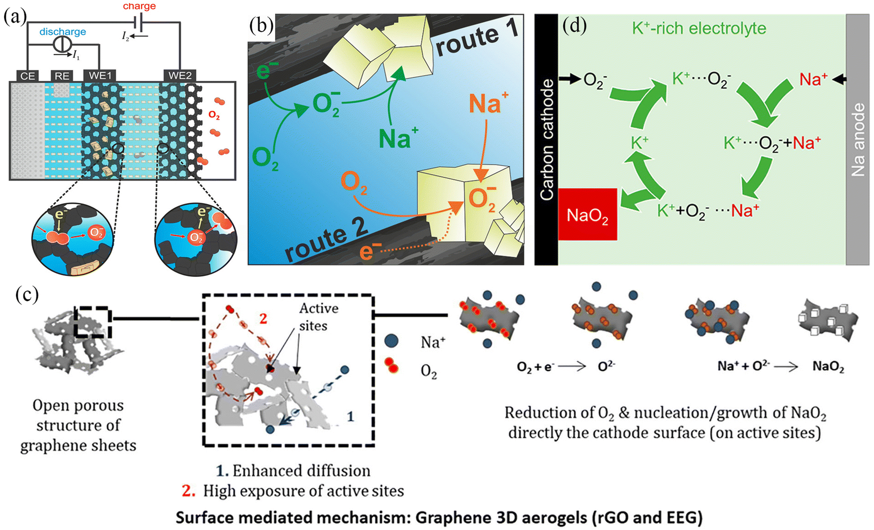 | ||
| Fig. 2 (a) Schematic illustration of the dual-working electrode in Na–O2 batteries. (b) Solution-precipitation route for NaO2 growth in Na–O2 batteries. (Reproduced from ref. 58 with permission from the American Chemical Society). (c) Schematic illustration of the surface-mediated mechanism of EEG electrode in Na–O2 batteries. (Reproduced from ref. 47 with permission from the Science Press and Dalian Institute of Chemical Physics, Chinese Academy of Sciences. Published by ELSEVIER B.V. and Science Press.). (d) Schematic illustration of the mechanism using K+-rich electrolyte in Na–O2 batteries. (Reproduced from ref. 61 with permission from the American Chemical Society). | ||
As mentioned earlier, organic sodium–air batteries with NaO2 as the main discharge product usually show lower overpotential and more prominent cycling stability. To achieve a higher reversible specific capacity of sodium–air batteries, it is important to optimize and control the nucleation/growth mechanism of NaO2 during the discharge process. Yang et al.62 investigated the relationship between the physical distribution and size of NaO2 formed during the discharge process and the current density used. During a small current density discharge (10 mA g−1), nano-sized (∼50–500 nm) NaO2 particles could be observed at the top, bottom, and sidewalls of the carbon nanotube (CNT) aggregate; however, during a high current density discharge of 1000 mA g−1, micron-sized NaO2 (∼2 μm) appeared only at the top and bottom of the CNT aggregate. The reason for this difference is due to the higher local supersaturation of (O2−–Na+)n agglomerates with low migration rates during the fast discharge, which nucleate rapidly at the top and bottom of the CNT aggregate, while (O2−–Na+)n agglomerates nucleate more slowly and diffuse more uniformly at low discharge rates, yielding more uniformly sized NaO2. In addition to the current density, the catalytic activity of the air electrode also has an obvious effect on the morphology and size of the discharge products. The bimodal transition metal oxide CaMnO3 electrode with excellent catalytic activity precipitated nanoscale cubic particles during the discharge process, while the cubic particles completely disappeared during the subsequent charging process.63 Alexis et al.64 investigated the effect of different electrodes on the formation of NaO2. The gas diffusion layer electrode formed discrete nano/micron NaO2 cubes during discharge, whereas the gas diffusion layer electrode modified with Au formed NaO2 flakes at the same current density. This is because the strong interactions between Au and O2/O2− increase the NaO2 nucleation rate, leading to change in the growth process. Such a phenomenon was also observed in Chen's research.65 Here, the boron-doped reduced graphene electrode covered by micron-scale RuO2 showed a longer cycle life and better electrochemical performance relative to both the reduced graphene electrode and the boron-doped reduced graphene electrode; this behaviour was attributed the higher affinity between micron-scale RuO2 and oxygen, while the amorphous Na2−xO2 is obtained at the end of the discharge. The RuO2-modified CNT electrode forms a less crystalline discharge product, NaO2, during the discharge process, while the morphology of the discharge product is drastically changed.66 The present results have shown that nano-sized NaO2 appears during the discharge process, which can be achieved not only by controlling the magnitude of current density during the discharge process, but also by selecting a suitable electrode type. Also the results show that no specific electrode type produces nano-sized NaO2 during discharge; moreover, it seems that the better the electrocatalytic performance of the air electrode, the more likely nano-sized NaO2 particles appear during discharge. There are two speculative reasons for these observations, on the one hand, the discharge products nucleate/grow quickly in the presence of highly catalytic of noble metal, while on the other hand, the highly active NaO2 is easy to decompose during the ex situ testing process and the results obtained by using in situ testing technique will be more credible.
2.2. Hybrid Na–air batteries
Fig. 1b shows the schematic illustration of a hybrid Na–air battery. During the discharge process, sodium metal at the anode is oxidized to Na+, while Na+ migrates from the anode to the air cathode through the solid electrolyte and aqueous electrolyte, and thus, the ORR reaction occurs at the air cathode to obtain the discharge product NaOH.45 In the subsequent charging process, the OER reaction occurs at the air cathode and electrons move from the cathode to the anode through the external circuit, while sodium metal is deposited on the anode. The chemical reaction equations involved in the discharge process are shown in eqn (10)–(12):| Anode: 4Na → 4Na+ + 4e− (E0 = +2.71 V) | (10) |
| Cathode: O2 + 2H2O + 4e− → 4OH− (E0 = +0.40 V) | (11) |
| Overall: 4Na + O2 + 2H2O → 4NaOH (E0 = 3.11 V) | (12) |
Hybrid Na–air batteries have a relatively simple reaction during energy storage and only one discharge product (NaOH) appears, significantly reducing side reactions and improving the cycle life. Meanwhile, the NaOH generated during discharge can be dissolved in the electrolyte, avoiding the accumulation of discharge products on the surface of the air cathode and improving the cycle efficiency. The cathode compartment electrolyte in the hybrid Na–air battery is NaOH solution, so the battery's output voltage can be controlled by adjusting the pH of the solution. The output voltage can be obtained from the Nernst equation, as shown in eqn (13):
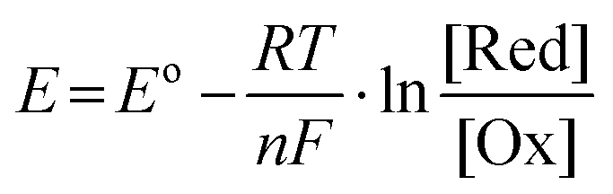 | (13) |
In summary, both organic Na–air batteries and hybrid Na–air batteries show bright application prospects. Sodium alkali metal reacts very violently with water, and thus organic Na–air batteries adopt organic electrolytes in both positive and negative chambers, thus improving the safety of organic sodium–air batteries. However, organic electrolytes are more expensive and prone to environmental pollution and have other associated problems. At the same time, the products formed during the discharge process of organic Na–air battery will be deposited on the surface of air electrode and gradually cover the redox active sites causing the degradation of the overall electrochemical performance of the battery. Moreover, the application conditions of organic Na–air batteries are relatively harsh, requiring dry oxygen source and gas purification devices in order to avoid the occurrence of side reactions, which will greatly increase the costs of application. Compared with organic Na–air batteries, hybrid Na–air batteries can directly use air as the oxygen source, which greatly reduces the costs. The products formed during the discharge process of hybrid Na–air batteries can be dissolved in the electrolyte of the cathode chamber, avoiding the degradation of battery electrochemical performance due to the accumulation of discharge products. Therefore, the hybrid Na–air battery exhibits low overpotential, high energy density (NaOH: 2090 W h kg−1; NaO2: 1105 W h kg−1, Na2O2: 1602 W h kg−1, Na2O: 1687 W h kg−1) and long cycle life. NASICON is an important component of the hybrid Na–air battery, which mainly separates the anode chamber and the cathode chamber, but the lower ionic conductivity of NASICON is not beneficial to the adequate operation of the air battery. The interfacial interaction between NASICON and the electrolyte needs to be further investigated, as it affects the internal resistance of the whole cell. For organic Na–air batteries and hybrid Na–air batteries, the rational design of the air cathode is the key to increase the comprehensive electrochemical performance of the battery. The air cathode is essentially a bifunctional catalyst with good OER/ORR activity. In addition to the bifunctional catalytic performance, the air electrode should be porous to facilitate gas diffusion and ion transport, which also expands the area for electrocatalytic reactions. The rational use of organic electrolytes and solute salts will promote the formation of stable SEI on the anodic side and thus further contribute to improving the air battery performance.
3. Air cathode materials
3.1. Carbon materials
An ideal air cathode material should have high surface area and abundant pore distribution inorder to: (1) maximise the contact between the electrolyte and the electrode, (2) fully utilize the active sites during the charging/discharging cycling, and (3) provide sufficient space to accommodate the discharge products (NaO2 and Na2O2). Carbon-based materials are widely used as cathode materials for Na–O2 batteries owing to their excellent physicochemical properties,11,22,31,69 including (i) large specific surface area, which exposes abundant redox active sites and accommodates higher amounts of discharge products at the same time; (ii) porous structure that facilitates full electrolyte infiltration and structural stability, while promoting oxygen diffusion; (iii) excellent electronic conductivity that facilitates electron transport, and (iv) low cost for high-volume fabrication. Carbon cloth and carbon paper have been used as cathode materials for metal–O2 batteries due to their low costs, but their poor cycling stability and limited specific capacity have restricted further applications.70 In recent years, a large number of carbon materials with different dimensions have been elaborately designed, such as two dimensional (2D) carbon thin film,28 CNT,31,54,71,72 carbon nanofiber (CNF),11,73,74 porous carbon spheres,75,76 graphene,50,51,77,78 reduced graphene oxide14 and porous carbon,53,79 and these have been widely used as cathode materials for Na–O2 batteries. Detailed information on carbon materials and their electrochemical performances are provided in Table 2.A novel Na–O2 battery design based on a carbon film cathode (Fig. 3a) was reported by Fu et al.28 The carbon thin film electrode exhibited a high specific capacity of 3600 mA h g−1 at a discharge rate of 1/60C at room temperature (Fig. 3b), which was significantly higher than the specific capacity exhibited by conventional cell cathode materials. The main discharge product was Na2O2, with Na2CO3 and NaOCO-R found in the fully discharged electrode, and these resulted from the decomposition of the electrolyte. Carbonate-based electrolytes are easily decomposed during cycling, forming many by-products (nNa+ + O2 + EC/DEC + ne− = Na2CO3 + NaOCO-R + [side products]), which are known to affect the cycling stability of Na–O2 batteries. In 2014, Zhou et al.52 used carbon nanotube paper as cathode material in Na–O2 batteries with a discharge-specific capacity of up to 7530 mA h g−1. This reduced the reaction depth and improved the cycling performance of Na–O2 cells when the cut-off capacity is limited to 1000 mA h g−1, while the overpotential was as low as 200 mV (Fig. 3c); the XRD results showed that Na2O2·2H2O was the main discharge product. Oxygen-containing functional groups on the electrode material surface play a key role in the electrochemical reaction mechanism of the metal–O2 cell. Sun's group73 controlled the air electrode's surface properties to investigate the effect of oxygen-containing functional groups on the composition and morphology of the discharge production (Fig. 3d). Hydrophobic and hydrophilic (containing a large number of oxygen-containing functional groups) carbon materials follow different reaction mechanisms in the discharge processes. During the discharge process, NaO2 crystal particles are formed on the hydrophobic cathode, but the presence of trace water in the electrolyte and the instability of NaO2 lead to the rapid transformation of NaO2 to Na2O2·2H2O and NaOH (Fig. 3e). Na2O2 2H2O, carbonate and other layered discharged products are formed on the hydrophilic cathode (Fig. 3f). Therefore, to ensure that the main discharge product of Na–O2 battery is NaO2, the water content of the battery electrolyte and the surface chemistry of the air electrode should be strictly controlled. Thus, controlling the discharge product composition during the discharge of Na–O2 battery is critical to improving the cycling stability.
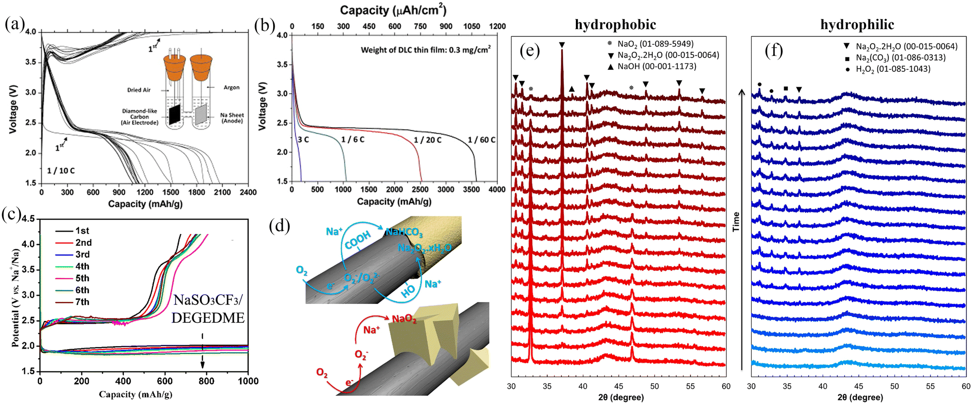 | ||
| Fig. 3 (a) Galvanostatic discharge/charge curves of the carbon thin film/Na cell at the current rate of 0.1C. The inset shows the composition of the Na–air cell (b) discharge profiles of carbon thin film/Na cell at different current rates. (Reproduced from ref. 28 with permission from the Elsevier). (c) The discharge/charge curves with a limiting capacity of 1000 mA h g−1 in the 0.5 M NaSO3CF3/DEGDME electrolyte with CNT papers as a cathode. (Reproduced from ref. 52 with permission from the Elsevier). (d) Schematic diagram of the formation of discharge products on the surface of carbon-based materials with different chemical properties during the discharge process. The XRD results for hydrophobic (e) and hydrophilic (f) air electrodes discharge in Na–O2 cells. (Reproduced from ref. 73 with permission from the American Chemical Society). | ||
Carbon nanotubes are a class of widely investigated carbonaceous materials which have a very bright prospect for use as the air cathode of Na–O2 batteries. In 2021, Wang et al.31 directly used CNTs as a cathode of Na–O2 batteries with different concentrations of ether-based electrolytes (NaCF3SO3/TEGDME). The results showed that the Na–O2 batteries exhibited excellent cycling stability (Fig. 4d) in the saturated electrolyte (1.6 M NaCF3SO3/TEGDME), and the battery cycling stability increased by four times. Scanning electron microscope (SEM) imaging was used to observe the morphologies of the CNT cathode with the same cut-off capacity at different electrolyte concentrations (Fig. 4a–c). The results showed that the amount of the discharge product increased with the electrolyte concentration suggesting a gradual decrease in the formation of the dissolved discharge product. This was confirmed by the results obtained from the UV/Vis absorption spectra of the discharge products. On immersing the CNT cathode in TiOSO4 solution after cycling at different electrolyte concentrations, it was observed that the solution colour and absorbance increased with the electrolyte concentration (Fig. 4e and f), suggesting a gradual increase of the discharge product content on the CNT cathode. At the same time, the oxygen content in the saturated electrolyte solution decreased dramatically, effectively reducing the Na electrode's oxidation level. Shao-Horn et al.62 observed that the size and distribution of Na–O2 batteries discharge products were highly dependent on the discharge rate. Both micron-sized and nano-sized NaO2 were formed at low discharge rates and were uniformly distributed inside and outside the carbon nanotubes; however, at a high discharge rate, micron-sized NaO2 was only distributed at the ends of the carbon nanotubes. This is due to the fact that sodium ions will firstly form O2−–Na+ small molecules during the discharge process, and then these small molecules will relocate in the electrode material. The O2−–Na+ small molecules will diffuse uniformly inside the anode material at low current densities instead of gathering rapidly to form NaO2 and the discharge products will grow slowly and be distributed more uniformly. However, O2−–Na+ small molecules will gradually gather to form O2−–Na+ aggregates, which have weaker migration ability compared to O2−–Na+ small molecules and thus will not be able to diffuse rapidly under high current density. This reduces the utilization of the active material and the battery capacity decay is more significant. The structure of the active material of the battery electrode has a remarkable influence on the electrochemical performance, particularly in the case of structurally diverse graphene-based carbon materials. At the same time, the electrochemical reactions, structural transformations and kinetics relevant to the charging and discharging of the materials should be explored in detail, which is necessary for the construction of high energy density Na–O2 batteries.
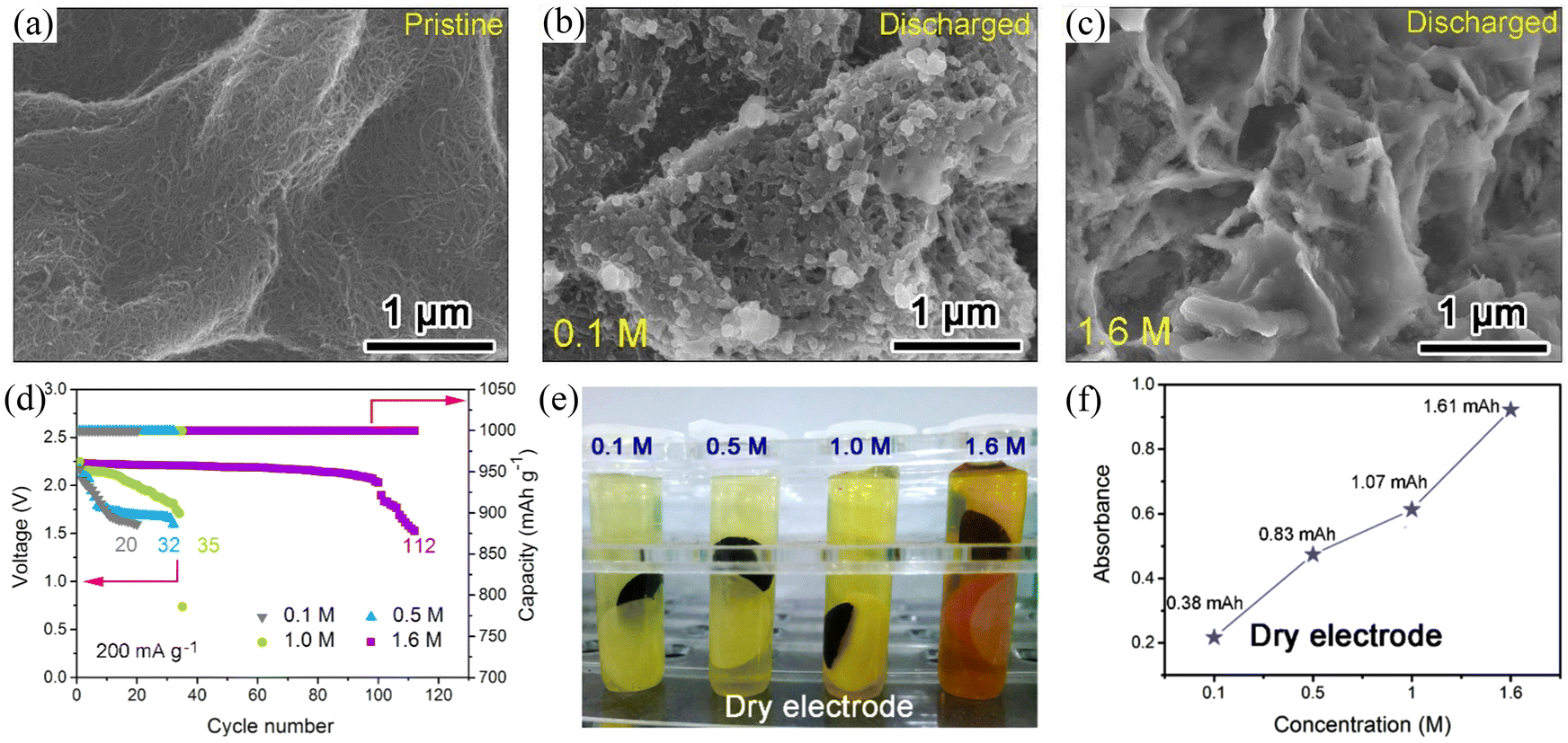 | ||
| Fig. 4 SEM images of (a) the pristine CNT cathode and the discharged CNT cathodes under the same discharge capacity in NaCF3SO3/TEGDME electrolyte at concentrations of (b) 0.1 M and (c) 1.6 M. (d) The long-term cycling performance of Na–O2 battery using CNT cathode in different concentrations of NaCF3SO3/TEGDME electrolyte. (e) Optical image of the dry CNT cathodes soaking in TiOSO4 solution after discharge to the same capacity in different NaCF3SO3/TEGDME electrolyte concentrations, and (f) the corresponding absorbance as a function of concentration. (Reproduced from ref. 31 with permission from Elsevier). | ||
Graphene is another widely used electrode material for rechargeable batteries. In 2013, Fu et al.51 used graphene nanosheets as Na–O2 battery cathodes for the first time and this led to an ultra-high discharge capacity of 6208 mA h g−1 at a current density of 300 mA g−1, which was three times higher than that of carbon electrode (2030 mA h g−1). At the same time, the graphene nanosheet electrode exhibited a lower overpotential compared to the thin film electrode. The above results indicate that graphene nanosheets are a promising candidate as cathodes for Na–air batteries. Air cathodes undergo gas transport and substance exchange during the charging/discharging process, so the porosity of the air cathode plays a critical role in the performance. The main technical challenge with graphene is the stacking of the nanosheets, which causes a considerable reduction of active sites and hindersoxygen gas diffusion, leading to rapid capacity decay. Ortiz-Vitoriano et al.77 investigated the electrochemical behaviour of reduced graphene aerogels with different porosities. The ArGO-N (randomly 3D oriented sheets) electrode exhibited a high discharge capacity of 6.61 mA h cm−2 at a current density of 100 mA g−1, which is higher than that of the ArGO-U (3D oriented sheets) cathode (1.72 mA h cm−2) and film (stacked sheets) cathode (0.06 mA h cm−2) (Fig. 5a). The disordered arrangement of nanosheets in ArGO-N exhibits more active sites providing large pore volumes and a suitable pore size distribution, which enhances material diffusion and exchange and promotes redox reactions (Fig. 5c). As a result, the ArGO-N electrode showed high stability after 39 cycles at a cut-off discharge capacity of 0.5 mA h cm−2 with a low overpotential of 250 mV (Fig. 5b). In addition, Sun et al.14 prepared a hierarchically porous reduced graphene oxide air battery cathode (Fig. 5d). This air electrode has a continuous network-like framework and suitably sized open pores, which facilitates fluent gas transport and ensures efficient utilization of the active sites (Fig. 5e). The small open pore-containing electrode (3DP-SP) exhibited a high discharge-specific capacity of 13 484.6 mA h g−1 at a current density of 200 mA g−1 (Fig. 5f). SEM images demonstrate that the discharge product NaO2 was uniformly distributed on the inner and outer sides of the 3DP-SP electrode due to the open pore channels on the electrode. The electrode also exhibited excellent cycling stability with a cut-off capacity of 500 mA h g−1 at a current density of 500 mA g−1 for 120 stable cycles. This work also suggests that the pore size in the air electrode has a significant effect on the performance of the air battery and that an oversized pore channel can reduce the effective mass of the electrode active material, leading to a degradation of the battery performance.
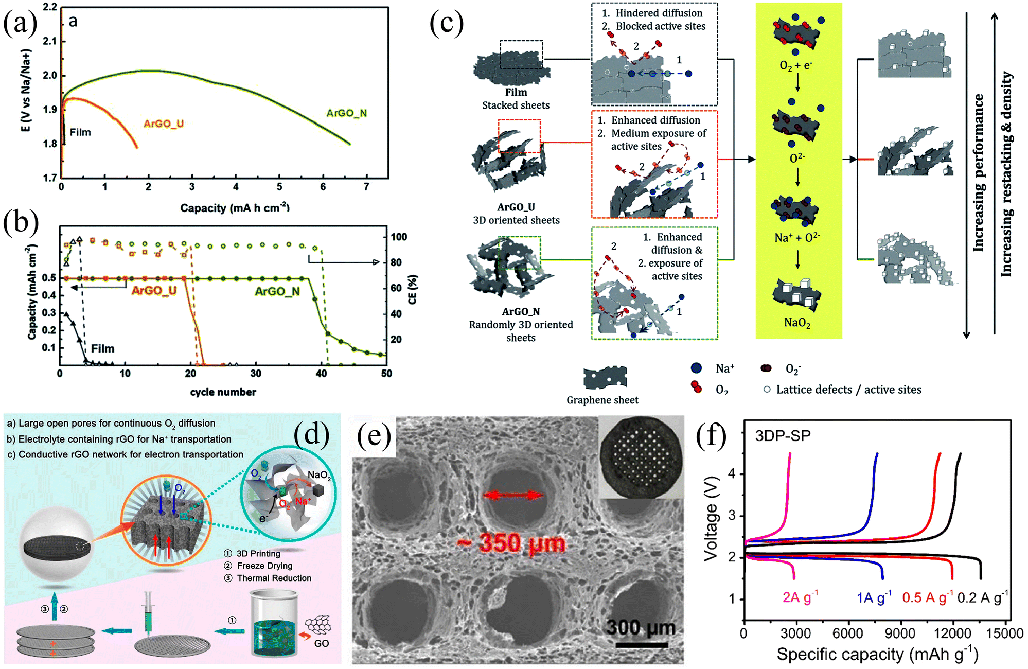 | ||
| Fig. 5 (a) Discharge curves of three different electrodes at the current density of 100 mA g−1. (b) The evolution of discharge capacity and Coulombic efficiency with the number of cycles for the three different electrodes. (c) Schematic illustration of the proposed mechanism for the three different electrodes. (Reproduced from ref. 77 with permission from the Royal Society of Chemistry). (d) Schematic illustration of the 3D-rGO air electrodes for Na–O2 battery. (e) SEM image of the 3DP-SP sample. (f) The initial discharge/charge curves of 3DP-SP cathodes at current density. (Reproduced from ref. 14 with permission from the American Chemical Society). | ||
In addition to various graphene-based electrode materials, porous carbon spheres (PCS) with high specific surface area have also been applied for use in Na–O2 batteries. Fig. 6a shows a schematic illustration of the synthesis of hierarchical PCS.76 The porosity of PCS can be precisely modulated and the pores inside and outside of PCS facilitate the diffusion of oxygen and the infiltration of electrolytes (Fig. 6b). The PCS cathode has a high specific capacity of 16 500 mA h g−1 in the initial cycle at a current density of 500 mA g−1, while it can be stably cycled for 150 cycles at a high current density of 2.0 A g−1 (Fig. 6c). More interestingly, the discharge product NaO2 is not precipitated in the form of cubic particles but was deposited on the surface of PCS in the form of a conformal film (Fig. 6d).
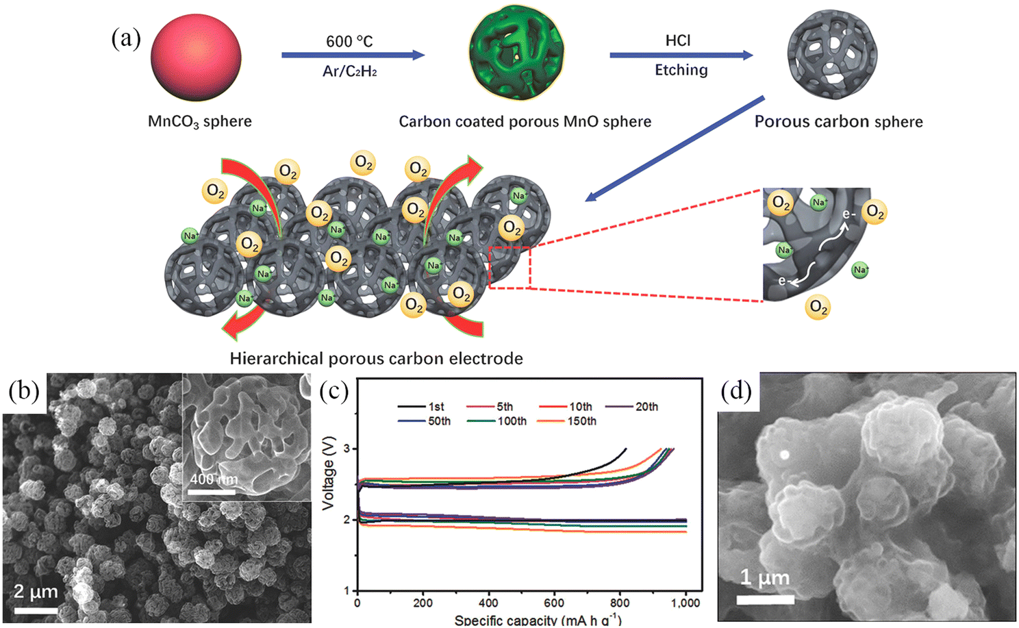 | ||
| Fig. 6 (a) Schematic illustration of the synthesis processes of PCS. (b) SEM images of PCS; The inset is a high magnification SEM image of the PCS. (c) Cycling at 2.0 A g−1 while curtailing the capacity to 1000 mA h g−1 and (d) SEM image of discharged PCS electrode. (Reproduced from ref. 76 with permission from the WILEY). | ||
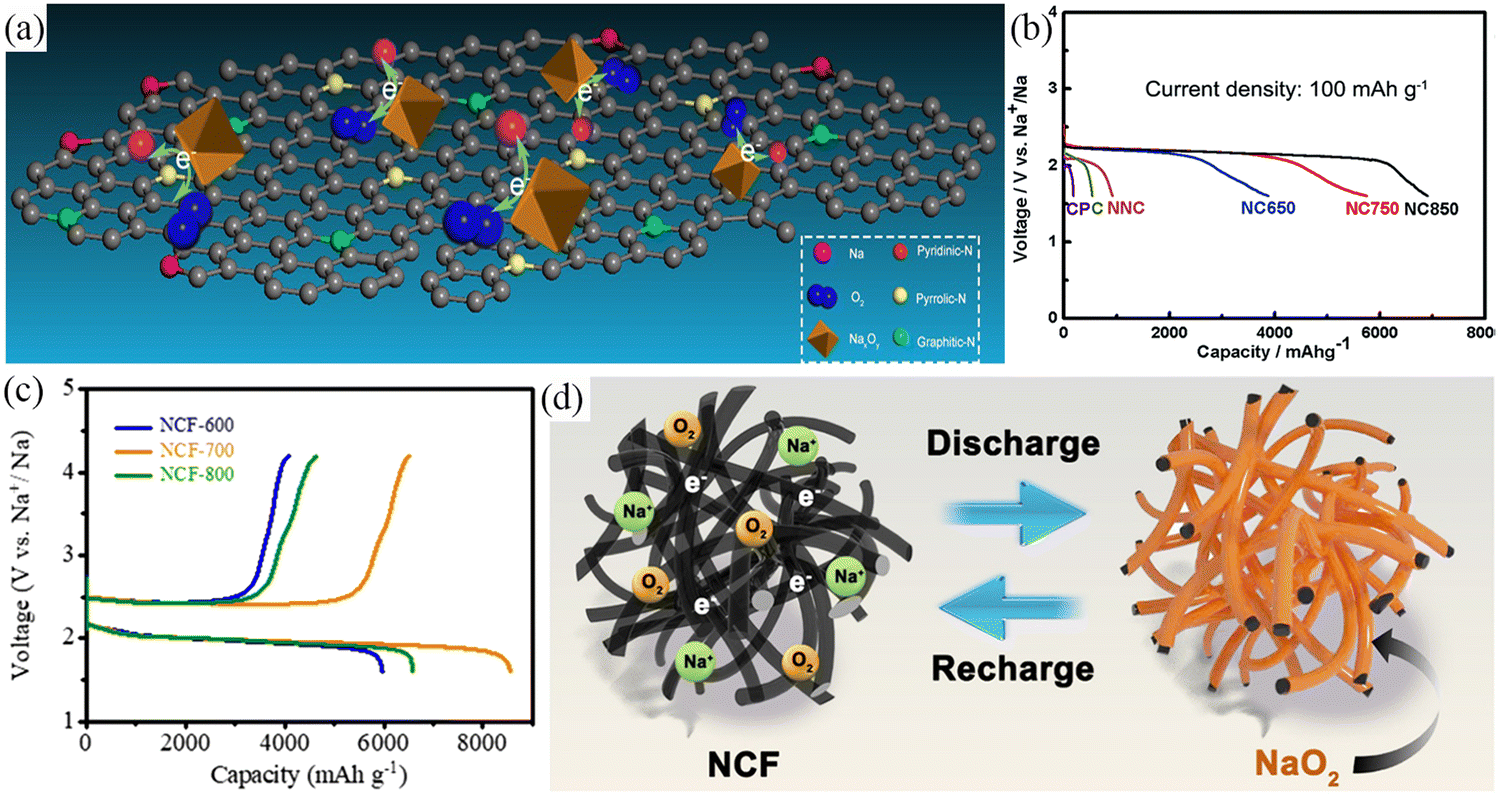
The catalytic activity of the material is mainly measured by the overpotential and stability of the catalyst. The carbon films show excellent catalytic activity, but the restricted specific surface area and active sites are not conducive to achievement of high catalytic activity. The development of carbon materials such as CNT, graphene oxide (GO), PCS with high specific surface area, abundant active sites and pores, have resulted in the materials showing higher reversible specific capacity and cycle life compared to carbon films. However, pure carbon materials show poor catalytic activity, with both experimental work and theoretical calculations proving that nitrogen doping can improve the electronic conductivity and catalytic activity of carbon materials leading to these electrodes exhibiting higher capacity, lower overpotential and longer cycle life.11 In addition, the presence of nitrogen heteroatoms is conducive to the uniform deposition of discharge products on the electrode surface, preventing pores from being blocked by granular products, and improving the long cycle life of the electrode.11,22,71,80 In 2013, Sun et al.50 introduced nitrogen atoms into graphene nanosheets, which resulted in superior electrochemical performance. This is due to the introduction of more active sites by nitrogen doping, resulting in smaller particle sizes and a more uniform distribution of the discharge products. Zhang's team79 prepared nitrogen-doped carbon (NC) using nitrogen-containing precursors. This process resulted in increased nitrogen content, increased specific surface area, and introduction of multi-sized pores (Fig. 7a). Electrochemical results showed that the NC with the optimized structure showed high catalytic activity, enhanced specific discharge capacity (6905 mA h g−1) and good cycle life (66 cycles) (Fig. 7b). In 2021, Wang et al.11 introduced nitrogen atoms into carbon nanofibers derived from polypyrrole (NCF) as an air cathode for Na–O2 batteries. The air cathode exhibited a low overpotential of 500 mV, a high specific capacity of 8554.7 mA h g−1 (Fig. 7c), and high stability after 90 cycles with NaO2 as the discharge product. The excellent electrochemical performance stems from the three-dimensional network structure with high electronic conductivity, specific surface area, and catalytic activity. The highly reactive N-groups optimize the surface adsorption energies of reactants and intermediates while controlling the uniform deposition of discharge products at the nanoscale (Fig. 7d). Notably, the heteroatoms doped in the preceding work were only nitrogen atoms and multi-heteroatom doping is expected to significantly improve the catalytic activity of the carbon materials. In addition, Pozo-Gonzalo and coworkers81 prepared multi-heteroatom-doped (S, N, and F) multilayer fibrous network-like structures. Owing to the promotion of oxygen adsorption and the synergistic effect of the different heteroatom dopants, the ORR activity during the discharge process was enhanced, and the discharge-specific capacity was effectively increased (0.35 mA h cm−2 at 0.6 mA cm−2). The catalysts showed excellent OER/ORR catalytic activity arising from the synergistic effect of heteroatom co-doping and mesoporous carbon structure. The heteroatom co-doping delivered a novel strategy for preparing a new generation of high-performance free-standing binder-free carbon-based air cathodes. These air cathodes have been assessed for Na–O2 batteries in a hybrid electrolyte composed of diglyme and ionic liquid and presented excellent long-term cycling (157 cycles). This value was higher than the case whereonly diglyme was used as an electrolyte.
 | ||
| Fig. 7 (a) Illustration of the decomposition of discharge products on N-doped carbon cathodes. (b) The discharge curves for Na–O2 battery with six different electrodes at current density of 100 mA g−1. (Reproduced from ref. 79 with permission from the Royal Society of Chemistry). (c) The discharge/charge profiles of the different NCF cathodes at 100 mA g−1. (d) Schematic illustration of the formation of discharge products (film-like layer NaO2) on NCF electrode surface during the discharge/charge process. (Reproduced from ref. 11 with permission from the Elsevier). | ||
3.2. Transition metal and metal oxides
Transition metals (TMs) and metal oxide (TMOs) catalysts are promising candidates for Na–O2 batteries. This is owing to these materials being inexpensive, environmentally friendly, and having remarkable catalytic activity when used in a wide range of electrolytes (aqueous and organic). Various transition metal-based catalysts have been widely used in Na–O2 cells such as transition metal compounds (CoB,82 CoP,15 and SnS283), TMOs (CoO,15 Co3O4,15,35,84,85 Mn2O3,86 α-MnO2,87 and VO2@rGO-carbon paper88) and transition metal composites (Co@ECNCFs).27 The electrolyte media includes NaOH, DME, TEGDME, and DEGDME. Detailed information related to transition metals and metal oxides and their electrochemical performance as cathodes is shown in Table 3.| Cathode | Electrolyte | Current density/mA g−1 | Initial discharge capacity/mA h g−1 | Overpotential/mV | Discharge product | Ref. |
|---|---|---|---|---|---|---|
| CoB | 0.5 M NaCF3SO3/TEGDME | 100 | 11482 |
∼600 | Na2O2, NaO2 | 82 |
| CoO/CoP | 0.5 M NaTFSI/TEGDME | 100 | 12654 |
∼650 | Na2O2 2H2O | 15 |
| CNT@Co3O4 | 0.5 M NaCF3SO3/DEGDME | 150 | ∼710 | ∼2100 | Na2O2, NaO2 | 84 |
| CNT/Co3O4 | 0.5 M NaCF3SO3/DEGDME | 150 | ∼555 | ∼2100 | Na2O2, NaO2 | 84 |
| VO2@rGO | 1.0 M NaCF3SO3/TEGDME//0.1M NaOH | 80 | 104 mW g−1 (power density) | 640 | NaOH | 88 |
| SnS2 | 1.0 M NaCF3SO3/TEGDME//0.1M NaOH | 5.0 | 300 mW g−1 (power density) | 520 | NaOH | 83 |
| MoS2/CC | 0.5 M NaCF3SO3/TEGDME | 0.1 mA cm−2 | 1.55 mA h cm−2 | ∼360 | Na2O2, NaO2 | 91 |
| α-MnO2@graphene | NaCF3SO3/TEGDME//0.1M NaOH | 15 | — | 700 | NaOH | 92 |
| Mn2O3 | 1.0 M NaCF3SO3/TEGDME//0.1M NaOH | 5.0 | 200 mW g−1 (power density) | 330 | NaOH | 86 |
| Co-ECNCFs | 0.5 M NaCF3SO3/TEGDME | 250 | ∼5350 | 1170 | Na2O2 | 27 |
| High-spin Co3O4 | 0.5 M NaCF3SO3/TEGDME | 100 | — | ∼60 | NaO2 | 35 |
| Co3O4 nanowire on carbon textiles | 0.5 M NaCF3SO3/TEGDME | 100 | 4687.2 | ∼1500 | Na2O2, NaO2 | 85 |
| CaMnO3 | 1.0 M NaCF3SO3/TEGDME | 100 | 9560 | ∼1300 | Na2O2, NaO2 | 63 |
| NiCo2O4 | 1.0 M NaClO4/DME | 20 | 1762 | 960 | Na2O2 | 93 |
| MnCo2O4/N-rGO | 1 M NaClO4/EC:DMC (1:1) with 1 vol% FEC//1.0 M NaOH |
0.13 mA cm−2 | — | 390 | NaOH | 94 |
| C@NiCo2O4-NAs | 1.0 M NaClO4/TEGDME | 50 | 6500 | 600 | Na2O2 | 95 |
In 2018, Yan et al.82 applied a solid-phase method for the controllable synthesis of porous CoB nanosheets (Fig. 8a). The CoB nanosheet cathode exhibited a high specific capacity of 11482 mA h g−1, low overpotential, and cycling stability of 74 cycles (Fig. 8b and c). The results obtained from theoretical calculations suggested that the excellent electrochemical performance can be attributed to the high electronic conductivity and unique porous structure of CoB. The abundant pores and larger specific surface area provide more catalytically active sites and O2/electrolyte diffusion channels, making such materials ideal for OER and ORR. Subsequently, Ko et al.83 synthesized 3D-structured SnS2 nanosheets using the solvothermal method as cathodes for Na–O2 batteries with mixed electrolytes (Fig. 8d). All working electrodes were observed to work in alkaline solution. The 3D structure of the SnS2 nanosheets provided paths for O2 and electrolyte diffusion, while the high specific surface area provided sufficient active sites. The cell's performance was compared with the cells made by Pt/C and activated carbon as air electrodes. The total cell overpotential of 520 mV (Fig. 8e) was very close to the overpotential of 470 mV for the Pt/C air electrode at 5.0 mA g−1 current density. When the current density was 240 mA g−1, the power density was measured to be 300 mW g−1, showing high stability after 40 cycles (Fig. 8f).
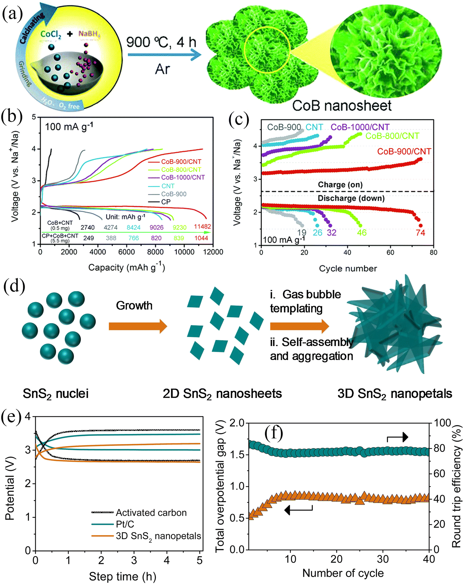 | ||
| Fig. 8 (a) Schematic illustration of the synthesis of CoB nanosheets. (b) Discharge/charge curves at a current density of 100 mA g−1 with different electrodes. (c) The voltage vs. the cycle number at 100 mA g−1 with a limited capacity of 2000 mA h g−1 for Na–O2 batteries with different electrodes. (Reproduced from ref. 82 with permission from the Royal Society of Chemistry). (d) Scheme illustration for the growth of 3D SnS2 nanopetals. (e) Galvanostatic charge/discharge curves of Na–O2 battery based on 3D SnS2 nanopetals and comparison with the Pt/C and activated carbon coated on carbon paper as air cathodes at 5.0 mA g−1. (f) Plot of overpotential and round-trip efficiency with cycles. (Reproduced from ref. 83 with permission from the Elsevier). | ||
Since gas/liquid transport is involved in the charge/discharge process, the electrocatalyst morphology should be strongly anisotropic, reducing diffusion paths and improving electrochemical performance. Cho et al.86 used a hydrothermal method to synthesize hollow double-walled Mn2O3 nanocubes, which maximized the diffusivity of electrolytes and oxygen, thus improving the gas-liquid transport processes (Fig. 9a–c). Moreover, the as-prepared Mn2O3 nanocubes possess ORR/OER bifunctional catalytic activity and thus have great potential as SAB air cathode materials. The SABs exhibited an overpotential of only 300 mV at a current density of 5 mA g−1 and a maximum power density of 200 mW g−1 (Fig. 9d). A well-performing air cathode requires a strongly anisotropic structure which exhibits a large surface-to-volume ratio, continuous electron conduction pathway, and excellent stability to facilitate gas-liquid transport, but it also requires high electrical conductivity to improve electrochemical kinetics. Zhang et al.27 fabricated Co-intercalated nitrogen-doped carbon fibers by electrospinning (Fig. 9e and f). The synergistic effect between nitrogen-doped carbon fibers and metallic Co endowed the composites with high electronic conductivity and catalytic activity. Moreover, the composite material can be directly applied to the air cathode of SABs, avoiding the addition of a binder to reduce the effective mass of active material. The three-dimensional porous structure formed by the interwoven carbon fibers facilitated the transport of matter and electrons. The outstanding structural features of the composites resulted in the SABs showing excellent electrochemical performance, including high discharge-specific capacity (6102 mA h g−1) by confining discharge cut-off potential to 1.6 V (Fig. 9g), low charge overpotential (200 mV), and long-cycle stability (112 cycles). Composites with similar structures include VO2 nanostructures on RGO/carbon paper (VGC)88 and atomic layer deposited (ALD) CNT@Co3O4.84Fig. 9h shows a schematic diagram of the synthesis of VGC composites.88 The composite exhibited a porous hierarchical structure with shortened electrolyte and oxygen diffusion paths (Fig. 9i). The VO2@rGO/carbon paper composite air cathode exhibited an overpotential of 640 mV and showed good stability over 50 cycles (Fig. 9j).
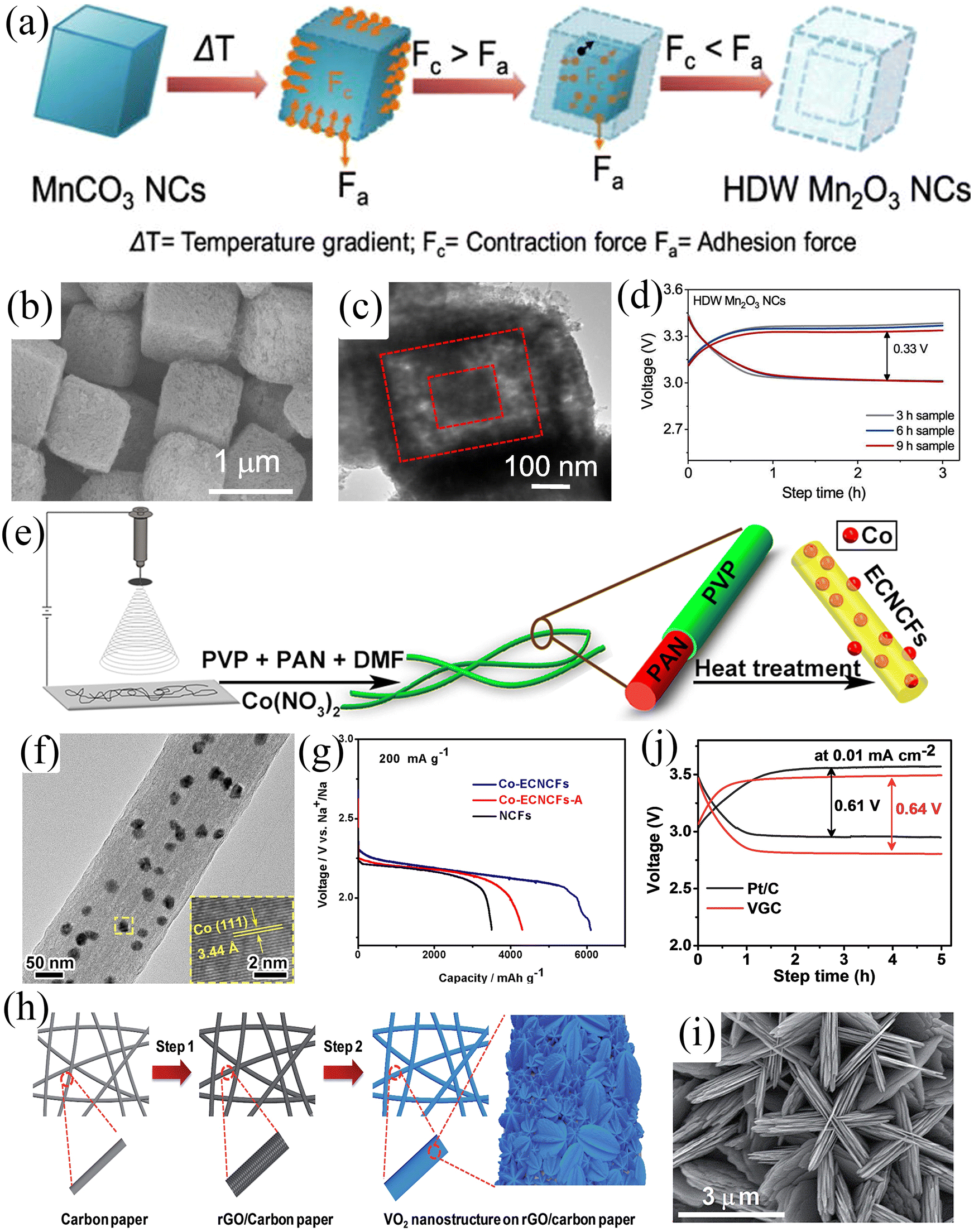 | ||
| Fig. 9 (a) Schematic illustration of the synthesis of hollow double-walled Mn2O3 nanocubes. (b) SEM and (c) TEM images of HDW Mn2O3 NCs. (d) Galvanostatic charge/discharge profiles of SABs at a current density of 5.0 mA g−1 built-up by Mn2O3 electrodes prepared via the hydrothermal method with different time intervals. (Reproduced from ref. 86 with permission from Elsevier). (e) Schematic illustration of the synthesis of Co-ECNCFs. (f) TEM image of Co-ECNCFs (inset: HRTEM image and the (110) lattice plane of Co particles). (g) Galvanostatic discharge curves at a current density of 200 mA g−1 with different electrodes. (Reproduced from ref. 27 with permission fromElsevier). (h) Schematic illustration of the synthesis of VGC. (i) SEM image of VGC. (j) The charge–discharge profiles of the assembled SABs using VGC and Pt/C electrodes at a current density of 0.01 mA cm−2. (Reproduced from ref. 88 with permission from the Royal Society of Chemistry). | ||
It is often difficult for one-component TMOs to have excellent ORR and OER activities simultaneously. For example, Co3O4 has good ORR activity, but the OER activity is usually not satisfactory, which has a negative effect on the electrochemical performance of the battery.89,90 Thus it is highly desirable to design bifunctional catalysts with excellent ORR and OER activities. In 2018, Liu et al.15 obtained CoO/CoP nanosheets with heterostructures by controlling the phosphating degree of Co(CO3)0.5(OH)0.11H2O nanosheets (Fig. 10a). This composite exhibited high ORR activity due to the presence of CoO and high OER activity due to the presence of CoP. Furthermore, O-P interpenetration at the interface to form a permeable layer improved the electron transfer, resulting in a simultaneous increase of the ORR and OER activities (Fig. 10b). The Na–O2 battery with CoO/CoP nanosheets as the air cathode exhibited higher initial specific capacity and longer cycle life (Fig. 10c).
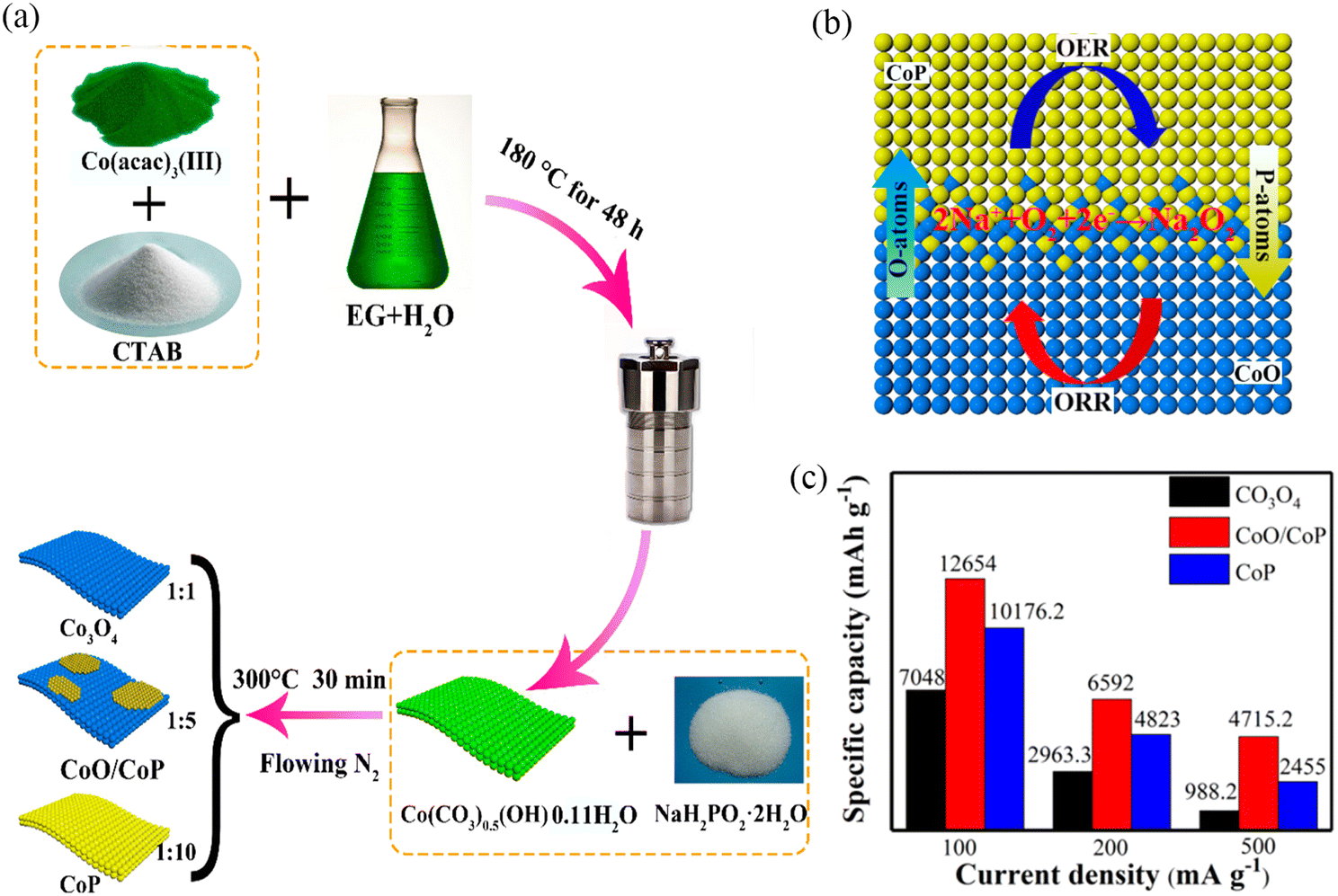 | ||
| Fig. 10 (a) Synthesis process of Co3O4, CoO/CoP and CoP nanosheets. (b) “O–P interpenetration effect” in CoO/CoP heterostructured nanosheet interface. (c) The initial discharge capacity at different current densities with different electrodes. (Reproduced from ref. 15 with permission from the American Chemical Society). | ||
3.3. Noble metal-based materials
Noble metals have excellent electrocatalytic activities and have received extensive attention in metal–air batteries because they can enhance electrocatalytic reaction kinetics by improving the interfacial interactions of reactants.96,97 The noble metals used in Na–O2 batteries mainly include Pt, Pd, Ru, Ag, and Au. Noble metal or noble metal oxides are often dispersed on substrates with large specific surface areas. For example, RuO2 has been dispersed on the surface of CNTs,66 Pt clusters on defective NiFe layered double hydroxide (LDH) surfaces,98 Ru on CNT surfaces,99 Ag nanoparticle-modified rGO,100 and Pd growth on Zn-O.101 Detailed information on noble metal materials and their electrochemical performance is shown in Table 4. Chen et al.65 synthesized m-RuO2-B-rGO which exhibited lower overpotential than B-rGO and rGO due to the strong attraction between micron-scale RuO2 and oxygen, forming an amorphous Na2−xO2 discharge product, which was identified by Raman spectroscopy (Fig. 11a). The product covered the RuO2 surface uniformly while avoiding reactions with defect sites to form by-products (Fig. 11b). The Na–O2 battery with m-RuO2-B-rGO cathode exhibited an overpotential of 700 mV at 0.05 mA cm−2 and was stable for more than 100 cycles at the current density of 0.05 mA cm−2. In addition, Shao and co-workers98 electrodeposited Pt clusters on Pt/NixFe-LDHs (Fig. 11c), which exhibited excellent trifunctional catalytic activity (HER/OER/ORR). The excellent electrochemical performance was attributed to: (1) increased electronic conductivity of LDHs, which improved the electrochemical kinetics, (2) the high specific surface area of LDHs, which facilitates the transport of reactants and products, (3) the synergistic effect between Pt clusters and defective LDHs. that promoted the adsorption of intermediates in the electrochemical process, and (4) the defects on LDHs that modified the electronic structure of the system, reducing the reaction energy barrier in the electrochemical process and accelerated the reaction kinetics (Fig. 11d). The hybrid Na–air battery based on the Pt/NixFe-LDHs binder-free cathode exhibited an open circuit voltage of 3.01 V, showing a low overpotential of ∼660 mV and cycling for over 1000 cycles. It yielded a lower overpotential (410 mV) compared to the pure noble metal-based air battery cathode (Fig. 11e), and the stability test results also revealed high stability (1000 cycles). This strategy provides a transformational approach for fabricating high-performance air-battery cathode materials.| Cathode | Electrolyte | Current density/mA g−1 | Initial discharge capacity/mA h g−1 | Overpotential/mV | Discharge product | Ref. |
|---|---|---|---|---|---|---|
| Pt@GNSs | 1.0 M NaClO4/PC | 0.1 mA cm−2 | 7574 | ∼1100 | Na2CO3 | 102 |
| Ag-RGO | 1.0 M NaPF6/TEGDME | 0.1 mA cm−2 | 566 (10th) | 1000–2000 | NaO2, Na2O2, Na2O | 100 |
| Pd/ZnO/C | 0.5 M NaCF3SO3/TEGDME | — | 7.5 mA h cm−2 | ∼500 | Na2O2 2H2O | 101 |
| Pt/NixFe LDH | 1.0 M NaClO4/TEGDME//0.1M NaOH | — | 838 | 410 | NaOH | 98 |
| CNT/Ru | 0.5 M NaClO4/DEGDME | 0.191 mA cm−2 | — | ∼1000 | Na2−xO2 | 99 |
| m-RuO2-B-rGO | 0.5 M NaCF3SO3/TEGDME | 0.05 mA cm−2 | 3.8 mA h cm−2 | ∼1000 | Na2−xO2 | 65 |
| RuO2/CNT | 0.5 M NaCF3SO3/TEGDME | 100 | 6157 | 370 | NaO2 | 66 |
| Ru-SAs@N-rGO | 0.5 M NaCF3SO3/DEGDME | 150 | — | ∼900 | Na2−xO2 | 18 |
| RuO2/Mn2O3/CNF | 0.5 M NaCF3SO3/TEGDME | 0.05 mA cm−2 | 9352 | ∼500 | NaO2 | 103 |
| Pt3Ni1/NixFe LDHs | 1.0 M NaClO4/TEGDME | 0.05 mA cm−2 | — | ∼350 | NaOH | 104 |
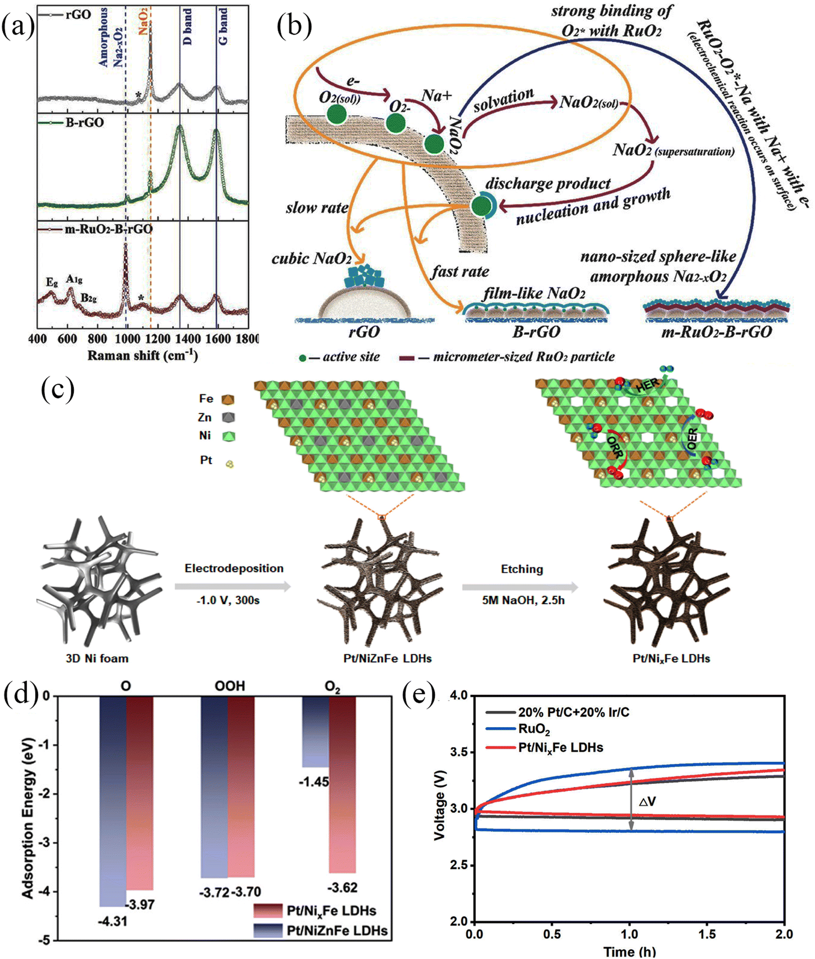 | ||
| Fig. 11 (a) Raman spectra of rGO, B-rGO, and m-RuO2-B-rGO electrodes. (b) Schematic illustration of the proposed mechanism for the formation of different morphologies of discharge products on different electrode surfaces. (Reproduced from ref. 65 with permission from Wiley). (c) Schematic illustration of the formation of Pt/NixFe LDHs. (d) Adsorption energies of intermediates on Pt/NiZnFe LDHs and Pt/NixFe LDHs surfaces. (e) The charge–discharge curves of 20% Pt/C + 20% Ir/C, RuO2 and Pt/NixFe LDHs electrodes. (Reproduced from ref. 98 with permission from the American Chemical Society). | ||
3.4. Perovskite (ABO3) and spinel oxides (AB2O4)
Perovskite oxides with physicochemical stability, excellent electronic conductivity, and high redox activity are widely used in the field of catalysis.105–109 The general formula of an ideal perovskite oxide compound is ABO3 (Fig. 12), where A is an alkali metal, lanthanide or alkaline earth metal with 12-fold octahedral ligands. B is a metal with a 3d, 4d or 5d configuration and a 6-fold cubic ligand.110 The ideal perovskite oxide shows a cubic Bravais lattice of space group Pm3m.111 It has been reported that 32 types of A elements and 54 types of B elements can form perovskite structures and these diverse compositions have laid the foundation for expanding their applications.112 At the same time, spinel oxides have the formula AB2O4, where A occupies the tetrahedral 8a site and B occupies the octahedral 16d site,113,114; these materials show similar physicochemical properties and high redox activity and stability and have been widely used in electrocatalysis.115–117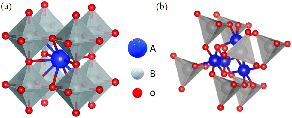 | ||
| Fig. 12 (a) Crystal structures of a cubic perovskite oxide (ABO3) (reproduced from ref. 118 with permission from the Royal Society of Chemistry) and (b) a spinel oxide (AB2O4). | ||
Na–O2 batteries suffer from slow ORR/OER kinetics and limited material transport. Noble metals such as Pt, Ru, Pd, and Au are often used for the air cathode of Na–O2 batteries to solve the problems of high overpotential and poor cycling stability. However, the high price is not conducive to its large-scale and widespread use. The common binary TMOs discussed previously (such as Co3O4, MnO2, Mn2O3) exhibit satisfactory electrocatalytic activity as cathode materials. However, ternary metal oxides such as ABO3 (perovskite)63 and AB2O4 (spinel)93–95 show better catalytic activity than binary metal oxides. This is due to the coexistence of multiple valences of metal cations causing intervalence charge transfer (IVCT),118,119 and/or the formation of oxygen vacancies and structural defects in the system,29,120,121 and these play an essential role in improving the catalytic efficiency. Detailed information on perovskite and spinel type materials and their electrochemical performances are summarised in Table 3. In 2015, Chen et al.63 synthesized porous CaMnO3 microspheres as air cathodes for Na–O2 batteries (Fig. 13a). The porous micro-nano structures provided abundant redox sites and exhibited remarkable electrocatalytic activity. Moreover, the size of the microspheres can be tailored by varying experimental conditions, such as the amount of carbonate precipitant and reaction temperature. The porous structure of CaMnO3 provides a high specific discharge capacity of 9560 mA h g−1 at a current density of 100 mA g−1 (Fig. 13b), and these can be steadily cycled for 80 cycles at a current density of 200 mA g−1 with the cut-off capacity of 1000 mA h g−1 (Fig. 13c).
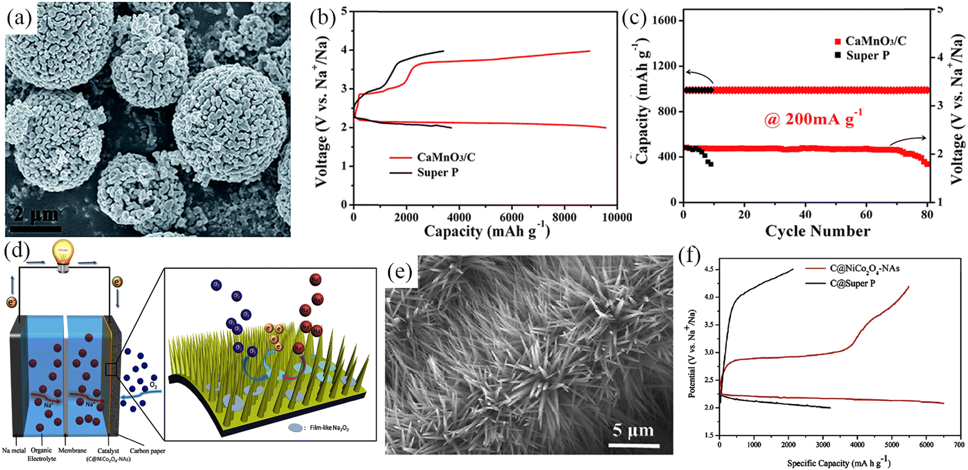 | ||
| Fig. 13 (a) SEM image of CaMnO3 nanoparticles. Discharge–charge curves (b) and cycling performance (c) of CaMnO3/C and Super P electrodes in Na–O2 batteries. (Reproduced from ref. 63 with permission from the Royal Society of Chemistry). (d) Schematic illustration of the Na–O2 batteries structure with C@NiCo2O4-NAs based cathode. (e) SEM image of C@NiCo2O4-NAs. (f) Initial charge–discharge curves of C@Super P and C@NiCo2O4-NAs electrode at 50 mA g−1. (Reproduced from ref. 95 with permission from Elsevier). | ||
Currently, cobalt metal-containing ternary transition oxides have attracted tremendous attention as electrocatalysts with high OER/ORR activity.122–125 During the cathode assembly, typically, a polymeric binder is required to maximize the physical contact between the active material and the current collector. However, this may result in a significant increase in the contact resistance and thereby reduce the battery performance. Further, the polymeric binder can undergo decomposition and cause side reactions.126 Fu et al.93 prepared a binder-free and carbon-free NiCo2O4/Ni foam composite air cathode, which provided an initial discharge-specific capacity of 1762 mA h g−1 at a current density of 20 mA g−1. However, TMOs generally lack sufficient electronic conductivity, cycling stability, and exposed surface area. Liu et al.95 fabricated sea urchin-like C@NiCo2O4 nanoneedles (C@NiCo2O4-NAs) in situ grown on carbon paper by a hydrothermal method and directly applied them to the air cathode of Na–O2 batteries (Fig. 13d and e). The C@NiCo2O4-NAs exhibited high specific surface area and low contact resistance, exposing a large number of catalytically active sites. Then, the C@NiCo2O4-NAs cathode released a high initial discharge specific capacity of 6500 mA h g−1 at current density of 50 mA g−1 (Fig. 13f) and showed high stability of 120 cycles. Further, the multi-layered structure produced was observed to be favorable for material transport and accommodating discharge products. Thin-film Na2O2 discharge products are formed on the nanoneedle surfaces and gaps and this unique structure facilitates decomposition of discharge products during subsequent charging, exhibiting a low overpotential of 600 mV.
Perovskite oxides with porous structures can enable adequate control of the composition and incorporation of functional materials, which are crucial for improving the catalytic activity, stability, and mass transport of catalysts. The catalyst morphology is also significant in improving the battery performance.118 First, the porous structure increases the contact area between the active material and the electrolyte and improves the ion storage capacity, while the porous structure promotes electron and ion transport. Second, the porous structure is conducive to material exchange, prevents the agglomeration of discharge products, and is beneficial for the electrode maintaining stability during cycling, achievement of long-term stability and prolongment of the cycle life. Third, electrodes with porous structures can help to optimize the interfacial interactions between air electrodes, discharge products, and electrolytes. In addition, introducing defects in the perovskite oxide is one of the most popular methods to improve catalytic performance, as this can allow for the modification of the crystal structure and improve the electronic conductivity and redox site density to prepare low-cost, catalytically efficient perovskite electrocatalysts. A-site cation substitution is a well-established approach to enhance the electrocatalytic activity and has been shown to improve the battery's power, energy density, and cycle life by increasing the electrical conductivity and reducing the cathode overpotential. Defects created by A-site cation substitution affect electrocatalytic performance in several ways, such as creating charge-compensated oxygen vacancies,127–131 generating charge-compensated B-site cation vacancies,128 and reducing the activation energy for cation, oxygen, or vacancy diffusion.112 Cerium-doped (La1−xCex)MnO3 (x = 0, 0.05, 0.1 and 0.15) chalcogenide oxides were prepared by Guo et al.132 using the sol–gel method. Ce replacement of La can effectively improve the ORR activity of perovskite due to the increase in the proportion of Mn4+ during the replacement process (Fig. 14a and b), which is beneficial for exchange of O22−/OH−, thereby improving the ORR performance. The B-site is usually considered the redox-active site for the OER/ORR reaction.133 The substitution of B-site cation can also be used to enhance the electrocatalytic activity of perovskite oxides. Cu/Co-doped LaMn0.8M0.2O3 (M = Cu, Co) perovskite oxides were synthesized by Hu et al.134 (Fig. 14c). The substitution of low-valent cations at the B-site increased the oxygen vacancy concentration and Mn4+ content, both of which favoured the ORR process. While Mn4+ has a more vital ability to accept electrons than Mn3+, the excess Mn4+ in the system promotes O2 evolution, which will improve the OER performance (Fig. 14d).
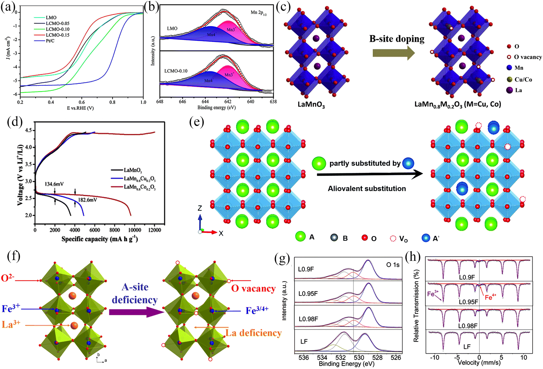 | ||
| Fig. 14 (a) Linear-sweep voltammetry curves at 1600 rpm with different samples. (b) XPS spectra of Mn 2p of prepared samples. (Reproduced from ref. 132 with permission from the American Chemical Society). (c) Structure of LaMnO3, La(Mn0.8M0.2)O3 (M = Cu, Co). (d) Initial charge–discharge profiles of LaMnO3 and La(Mn0.8M0.2)O3 (M = Cu, Co) at 500 mA g−1. (Reproduced from ref. 134 with permission from Elsevier). (e) Schematic illustration of the formation of oxygen vacancies due to A-site substitution. (Reproduced from ref. 112 with permission from the Royal Society of Chemistry). (f) Schematic illustration of the formation of Fe4+ and oxygen vacancies in A-site-substitution La1−xFeO3−δ. (g) XPS spectra of O 1s and (h) Mössbauer spectra of LaFeO3, La0.98FeO3−δ, La0.95FeO3−δ, and La0.9FeO3−δ samples. (Reproduced from ref. 135 with permission from the American Chemical Society). | ||
The formation of anion vacancies in perovskite oxides is another strategy to tailor the functionality of materials for OER/ORR. For instance, oxygen vacancies in the defective perovskite oxides (ABO3−δ) showed an enhancement in the oxygen ion mobility.112 Typically, there are two main approaches for the creation of oxygen vacancies: (1) cation substitution-induced oxygen vacancies and (2) elemental non-chemical stoichiometry-induced oxygen vacancies.112 The partial introduction of donor dopants in the A-sites is the most common method to generate oxygen vacancies and this has been shown to enhance the electrocatalytic activity (Fig. 14e). These defects are created based on the charge compensation mechanism.112,118 The oxygen vacancies can be formed when the perovskite oxide is heated under a reducing atmosphere. Nonetheless, these vacancies have been observed to be unstable with prolonged exposure to air. Another strategy to create oxygen vacancies involves the formation of A-site vacancies. For example, Shao's group135 prepared La1−xFeO3−δ (x = 0.02, 0.05, 0.1) OER/ORR bifunctional electrocatalysts with the absence of A-site cations (Fig. 14f). The OER/ORR performance of La1−xFeO3−δ was significantly improved compared to the untreated samples with La0.95FeO3−δ showing the best OER and ORR activities. The XPS results (Fig. 14g) can be analyzed to obtain La1−xFeO3−δ perovskite oxides with A-site cation deficiency that have surface oxygen vacancies (O22−/O−), and the OER/ORR reactions occur on the surface of perovskite oxides with the surface oxygen vacancies enhancing the OER and ORR reactions. The XPS and Mössbauer spectra of La1−xFeO3−δ (Fig. 14g and h) showed the presence of high chemical valence iron (Fe4+) in the treated samples and the presence of Fe3+/Fe4+ redox couple enhanced the electrocatalytic performance of La1−xFeO3−δ.
The defect engineering (A-site substitution/absence, B-site substitution/absence, anion absence) of perovskite oxides leads to a significant improvement in OER and ORR catalytic activities of perovskite oxides, which is beneficial for increased applicability in electrocatalysis, fuel cells, and metal–air batteries. A summary of approaches that have been used to create defects in perovskite electrocatalysts and their applications for ORR/OER or metal–air batteries are summarised in Table 5.
| Perovskites | Dopant and defect type | Method | Application | Ref. |
|---|---|---|---|---|
| La0.9CoO3−δ | La and O vacancies (O22−/O−: 56.2%) | Polymer-assisted (A-site cation deficiency) | ORR/OER | 127 |
| (La0.8Sr0.2)1.05MnO3 | Mn and O vacancies (O22−/O−: 32.1%; Mn3+: 32.8%) | Polymer-assisted (A-site cation excessive) | ORR/OER | 128 |
| Pr(Ba0.5Sr0.5)(Co1.9Ni0.1)O5+δ | Ni dopant (Oads/Olat: 2.48) | Pechini method (elemental doping) | Zn–air battery | 136 |
| La0.3(Ba0.5Sr0.5)0.7Co0.8Fe0.2O3−δ | La dopant and O vacancies | Polymerized complex method (elemental doping) | ORR/OER | 137 |
| La(NixM1−x)O3 (M = Co, Mn, Fe) | Ni dopant | Sol–gel method (elemental doping) | ORR/OER | 138 |
| BaBi0.05Co0.85Nb0.1O3−δ | Nb dopant and O vacancies (Oads/Olat: 1.85) | Solid state reaction (elemental doping) | ORR/OER | 139 |
| 5.84% S–LaMO3 (M = Co, Fe, Ni) | S dopant (O: 71.7%) | Sol–gel method and anneal (elemental doping) | Zn–air battery | 140 |
| P-doped LaFeO3−δ | P dopant and O vacancies (O22−/O−: 30.6%) | Sol–gel method and anneal (elemental doping) | ORR/OER | 141 |
| Sr0.95Nb0.1Co0.8Ni0.1O3−δ | O vacancies (O22−/O−: 7.18%) | Heat treatment in H2/Ar | ORR/OER/HER | 142 |
| (La1−xCex)MnO3 | Ce dopant | Sol–gel method (elemental doping) | Zn–air battery | 132 |
| (Pr0.5Ba0.5)CoO3−δ | Element dopant | Sol–gel method (elemental doping) | Zn–air battery | 143 |
| La(Mn0.8Co0.2)O3 | Element dopant (Mn4+/Mn3+: 0.55) | Gel-combustion | Li–O2 battery | 134 |
| (La0.8Sr0.2)(Co0.8Ni0.2)O3−δ | Element dopant and O vacancies (O−/O2−: 5.94% OH−/CO32−: 53.64%) | Sol–gel method (elemental doping) | Li–O2 battery | 144 |
3.5. Metal–organic frameworks and their derivatives
Metal–organic frameworks (MOFs) are obtained by the reaction of metallic complexes and organic linkers in a specific environment. The coordination reaction between metal nodes and organic ligands results in a porous network structure and endows MOFs with a large specific surface area, which is conducive to material contact, transport and exchange and ensures the continuation of chemical reactions.145–147 The abundant pores, diverse crystal structures, and outstanding redox activity in MOFs make them widely applicable for energy conversion.148 In particular, the application of MOFs and their derivatives in bifunctional catalysts (OER/ORR) and their extension (metal–air batteries) provides a natural advantage (Fig. 15a).149 Metal–air batteries involve gas transport and material conversion during the charge/discharge process and MOFs with porous crystal structures can be designed to meet application requirements. Combining MOFs with other electrocatalysts with excellent OER/ORR activity is also possible, which can exhibit even better electrochemical performance. In addition, using MOFs as precursors for MOF-based derivatives can help preserve the basic framework of MOFs to obtain a hierarchical porous structure, which facilitates the electrochemical mass transfer process. The choice of metal nodes and organic linkers is also significant for OER/ORR activity. The metal cation species and valence states affect the organic ligands' spatial arrangement to form MOFs with different electrochemical properties. Guo et al.150 synthesized a series of 2D metal–organic frameworks M3(C6S6)2 (M = V, Cr, Mn, Fe, Co, Nb, Mo, Tc, Ru, Rh, Pd, Ir, and Pt) with different metal centres (Fig. 15b). M3(C6S6)2 exhibited different catalytic activities (Fig. 15c) owing to the presence of metal nodes with different numbers of simple d-electrons. The OER and ORR overpotentials of Rh3(C6S6)2 were 430 and 420 mV, respectively, showing the best bifunctional catalytic activity. The organic ligands enable the metal cation active sites to be uniformly distributed in the MOF framework. During the preparation of MOF-derived carbon materials, the ligand bonds in the system break and the metal centres are dispersed throughout the carbon skeleton. Ma's team151 used a stepwise self-assembly method to load Ni and Fe single atoms on the inner and outer walls of hollow carbon spheres, respectively (Fig. 15d), resulting in composites with good bifunctional catalytic activity. Both experimental and theoretical calculations demonstrate the excellent ORR activity of the inner wall Fe–N4 cluster (Fig. 15e), as judged by a high half-wave potential of 0.83 V. The outer Ni–N4 cluster exhibits excellent OER electrocatalytic activity, which delivered a low overpotential of 400 mV (Fig. 15f). In summary, both pristine MOFs and the MOF derivatives show excellent bifunctional catalytic activity and have outstanding application prospects in Na–O2 batteries. Detailed information on metal–organic frameworks, their derivatives, and their electrochemical performance is provided in Table 6.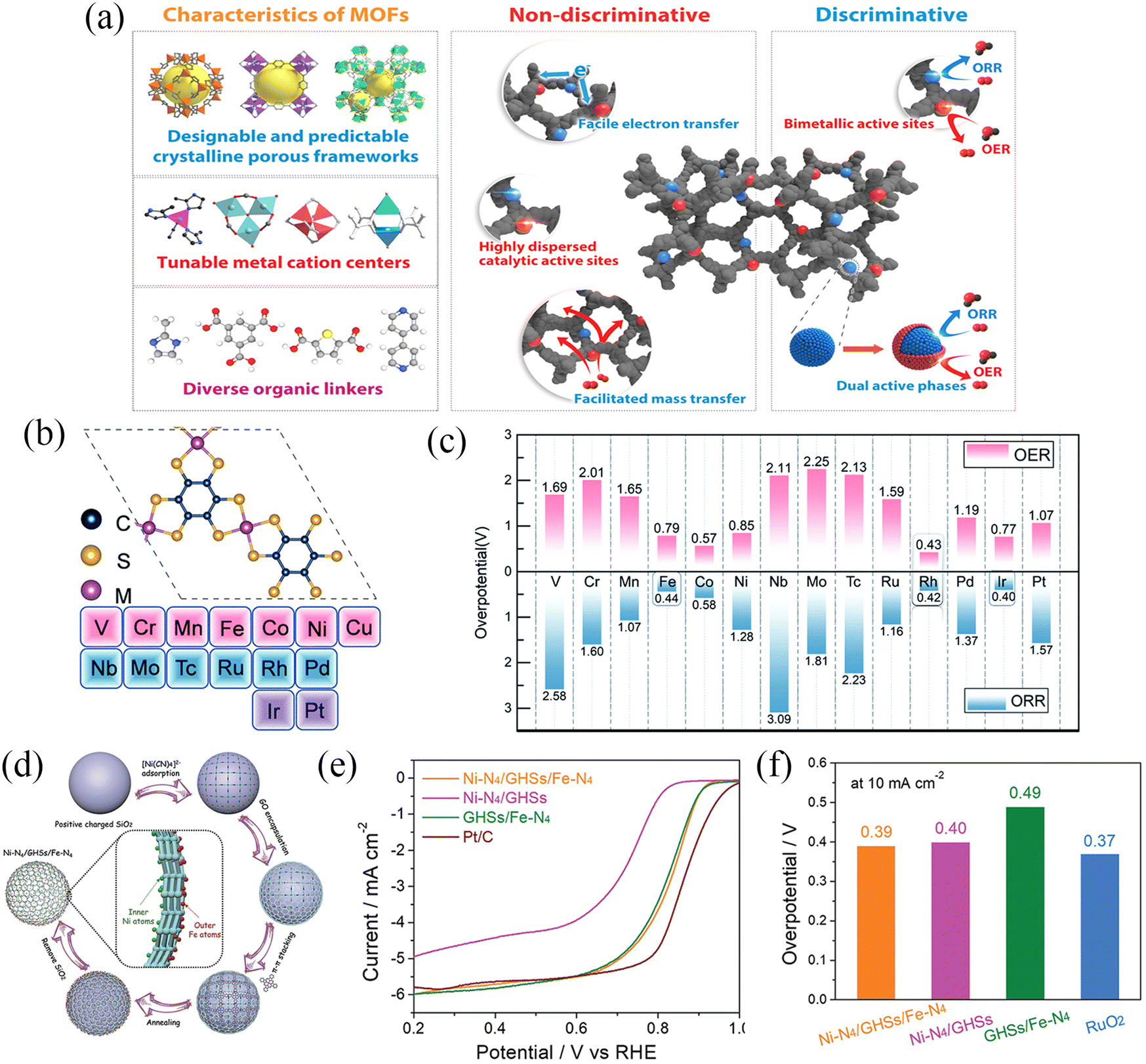 | ||
| Fig. 15 (a) Schematic illustration of the outstanding features of MOFs and their derivatives in OER and ORR application. (Reproduced from ref. 148 with permission from Elsevier). (b) Schematic illustration of M3(C6S6)2 with different transition metals. (c) OER and ORR overpotentials of M3(C6S6)2. (Reproduced from ref. 150 with permission from the Royal Society of Chemistry). (d) Synthesis procedure for the Ni–N4/GHSs/Fe–N4 catalyst. (e) The ORR results and (f) the OER results of different catalysts. (Reproduced from ref. 151 with permission from Wiley). | ||
| Cathode | Electrolyte | Current density/mA cm−2 | Overpotential/mV | Discharge product | Ref. |
|---|---|---|---|---|---|
| D-Co-PBA + Pt/C | Cathode: 0.1 M NaOH | 0.01 | 150 | NaOH | 152 |
| MOF-NCNTs-N2-4 | 1.0 M NaClO4 in EC/DMC (1:1) with 1 vol% FEC)//1.0 M NaOH |
0.1 | 350 | NaOH | 157 |
| MOF-NCNTs | 1.0 M NaClO4 in EC/DMC (1:1) with 1 vol% FEC)//1.0 M NaOH |
0.1 | ∼200 | NaOH | 153 |
| Co–N–C-0.5 | 1.0 M NaClO4 in EC/DMC (1:1) with 1 vol% FEC)//1.0 M NaOH |
0.1 | 310 | NaOH | 154 |
| Co–Fe@NC | 1.0 M NaClO4 in EC/DMC/EMC (1:1:1) with 5 vol % FEC//1.0 M NaOH |
0.1 | ∼205 | NaOH | 155 |
| Fe–N4/CNT | 1.0 M NaCF3SO3/TEGDME//0.1 M NaOH | — | — | NaOH | 158 |
| Fe-NiCoP@C | Cathode: 0.1 M NaOH | 0.01 | 140 | NaOH | 17 |
| h-Co3O4@MnCo2O4.5 | 1.0M NaClO4/TEGDME | 50 mA g−1 | 450 | Na2O2 | 156 |
| Na2−xO2 | |||||
| Bi2Ru2O7 | 1.0 M NaCF3SO3/TEGDME//0.1 M NaOH | 0.01 | ∼210 | NaOH | 26 |
| La2Co2O7 | 0.5 M NaCF3SO3/TEGDME | 100 mA g−1 | ∼500 | Na2O2, NaO2 | 159 |
| Tl2Rh2O7 | 1.0 M NaCF3SO3/TEGDME | 0.01 | ∼500 | NaOH | 160 |
| P-Bi2Rh2O6.8 | 1.0 M NaCF3SO3/TEGDME//0.1 M NaOH | 0.01 | ∼170 | NaOH | 161 |
| P-Tl2Ru2O7 | 1.0 M NaCF3SO3/TEGDME | 0.01 | ∼160 | NaOH | 162 |
| Na2CoPO4F | 1.0 M NaClO4 in PC//0.1 M NaOH | 0.01 | 417 | NaOH | 163 |
| Ni1.5Co1.5(PO4)2 | 1.0 M NaClO4 in PC//0.1 M NaOH | 0.01 | ∼750 | NaOH | 164 |
| Co3(PO4)2 | 1.0 M NaCF3SO3/TEGDME//0.1 M NaOH | 0.01 | 230 | NaOH | 165 |
| K2Co(PO3)4 | 1.0 M NaClO4 in PC//0.1 M NaOH | 0.02 | ∼500 | NaOH | 16 |
Hui et al.152 proposed a post-oxidation strategy for the insufficient OER activity of Co-PBA and prepared defective Prussian blue analogues with exposed Co(III) active sites and Fe(CN)6 vacancies (D-Co-PBA) (Fig. 16a). Theoretical calculations demonstrated that Fe(CN)6 vacancies modulate the electronic structure of the entire D-Co-PBA to lower the reaction energy barrier of the decisive step in the OER process and improve the reaction kinetics of the OER process. The D-Co-PBA catalyst showed an overpotential of only 400 mV at a current density of 10 mA cm−2 (Fig. 16b). The D-Co-PBA(OER)-Pt/C(ORR) bifunctional catalyst was used as the air cathode electrode of a hybrid Na–O2 battery. The bifunctional air cathode exhibited a very low overpotential of 150 mV at a current density of 0.01 mA cm−2, which is lower than the overpotential of the Ir/C(OER)-Pt/C(ORR) bifunctional cathode (Fig. 16c).
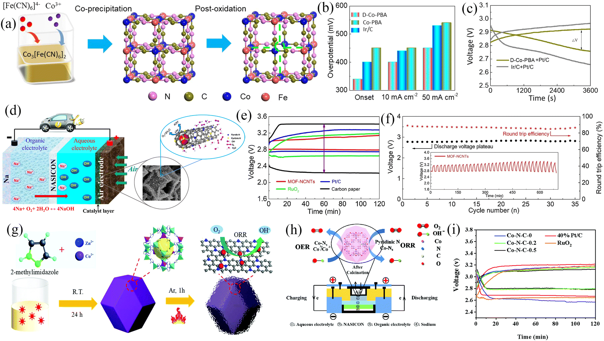 | ||
| Fig. 16 (a) Schematic of synthesis route of Co-PBA and D-Co-PBA. (b) The comparison of overpotential at different states for Ir/C, Co-PBA and D-Co-PBA electrodes. (c) Charge–discharge curves of Na–O2 batteries using different electrodes at current density of 0.01 mA cm−2. (Reproduced from ref. 152 with permission from Elsevier). (d) Schematic illustration of a hybrid Na–air battery and the ORR/OER process at the surface of Co confined in MOF-NCNTs. (e) Charge–discharge curves of Na–O2 batteries with MOF-NCNTs, Ru/O2, Pt/C and carbon paper electrode at 0.1 mA cm−2. (f) Long-stability performance of Na–air batteries with MOF-NCNTs as bifunctional catalyst at 0.1 mA·cm−2 for 35 cycles. (Reproduced from ref. 153 with permission from Elsevier). (g) Synthesis schematic of Co–N–C-x. (h) Schematic illustration of a typical hybrid Na–air battery. (i) The discharge-charge profiles with different electrodes. (Reproduced from ref. 154 with permission from the Royal Society of Chemistry). | ||
In addition to the direct use of MOFs as air cathodes for Na–O2 batteries, MOF-based derivatives can also be prepared for use in air cathodes for Na–O2 batteries. In 2019, Sun et al.153 prepared MOF-NCNFs using ZIF-67 as a precursor (Fig. 16d). Under reducing atmosphere (Ar/H2) at 700 °C, the ZIF-67 precursors were pyrolyzed and converted into a robust framework structure. The synergistic effect of the nitrogen-doped carbon framework containing Co nanoparticles in the framework structure induces more oxygen adsorption and electrocatalytically active sites to promote electron transfer in OER and ORR processes. At the same time, the stable porous carbon skeleton facilitates the smooth mass transfer process and contributes to the stability of the catalyst during the charging and discharging process for a hybrid Na–O2 battery. MOF-NCNFs exhibited an overpotential of 300 mV at a current density of 0.01 mA cm−2, which was superior to commercial RuO2 (500 mV), Pt/C (500 mV), Co-CNTs (670 mV), NCNTs (770 mV), multi-walled carbon nanotubes (MWNTs) (900 mV) and carbon paper (1180 mV), and could be stably cycled for more than 35 cycles (Fig. 16e and f). Subsequently, Xue et al.154 synthesized highly dispersed Co nanoparticle-modified N-doped defect carbon framework (Co–N–C) using ZnCo bimetal–organic framework as a precursor for hybrid Na–O2 battery (Fig. 16g). Nitrogen-doped defective carbon, CoNx, and Co nanoparticles in Co–N–C can serve as OER and ORR active sites, while Co–N–C species connect carbon materials with Co particles and facilitate interfacial electron transfer (Fig. 16h). The Co–N–C-0.5 anode with a high number of active sites, strong internal synergy, and significantly enhanced electron transfer capacity exhibited only an overpotential of 310 mV along with a 90.0% round-trip efficiency at a current density of 0.1 mA cm−2 (Fig. 16i). In addition to monometallic derivatives, bimetallic derivative electrocatalysts have been prepared. Hui et al.155 prepared bimetallic nanoparticles encapsulated in nitrogen-doped carbon (Co–Fe@NC) for hybrid Na–air batteries and the Co–Fe@NC air cathode exhibited lower overpotential (270 mV) and long cycle life (700 h) in comparison to the Pt/C + RuO2 electrode (overpotential increased to 1330 mV after 400 h).
Many studies also used MOFs as precursors to prepare metal oxides156 and metal phosphides.17 Liu et al.156 synthesized the hierarchical Co3O4@MnCo2O4.5 nanocubes (h-Co3O4@MnCo2O4.5 NCs) with a core-shell structure using cubic ZIF-67 precursor (Fig. 17a–c). The abundant pores in h-Co3O4@MnCo2O4.5 NCs facilitated the transport and exchange of substances during the recycling process and significantly enhanced the electrocatalytic activity. The Na–O2 batteries based on h-Co3O4@MnCo2O4.5 Ns cathode exhibited a high specific discharge capacity of 8400 mA h g−1 (Fig. 17d) and showed high structural stability after 135 cycles. Further, Hui et al.17 synthesized three-dimensionally-structured Fe-doped NiCoP (Fe-NiCoP) on nickel foam (Fig. 17e and f) and used it as a bifunctional air cathode for Na–O2 batteries. Fe-doping significantly improved the electrocatalytic performance of NiCoP, while carbon coating (Fe-NiCoP@C) facilitated the enhancement of catalytic performance and stability. The linear cyclic voltammetry (LSV) curves of different electrodes are shown in Fig. 17g. Compared to NiCoP (0.64 V) and Fe-NiCoP (0.80 V), Fe-NiCoP@C showed a maximum onset potential of 0.81 V. In addition, Fe-NiCoP and Fe-NiCoP@C showed higher limit current densities and better ORR performance than NiCoP. Meanwhile, Fe-NiCoP@C exhibited an overpotential of 270 mV at a current density of 10 mA cm−2 (Fig. 17h), which is lower than reported for most OER catalysts. First-principles calculations (DFT) revealed the origin of the high catalytic activity of Fe-NiCoP@C. Fig. 17i and j presents the Gibbs free energies (ΔG) of the relevant intermediates in the ORR/OER process for two samples (Fe-NiCoP and NiCoP). In the ORR process, the formation of OH− is a rate-determining step. It was shown that the presence of Fe in Fe-NiCoP, compared to NiCoP, considerably increased the adsorption strength of the intermediate ˙OH and reduced the overpotential (Fig. 17i). In the OER process, Fe doping was found to be more favorable for the formation of ˙OOH, and thus, Fe-NiCoP exhibited superior OER activity (Fig. 17j). The binder-free Fe-NiCoP@C electrode was able to be stably cycled for 500 cycles at 0.01 mA cm−2 with the highest power density of 621 mW g−1.
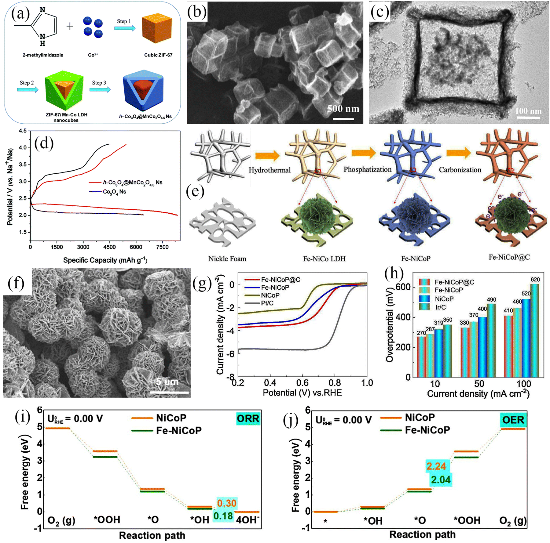 | ||
| Fig. 17 (a) Scheme for the preparation of h-Co3O4@MnCo2O4.5 Ns. (b) The SEM image and (c) The TEM image of h-Co3O4@MnCo2O4.5 Ns. (d) The initial discharge/charge profiles of Na–O2 batteries with h-Co3O4@MnCo2O4.5 Ns and Co3O4 Ns electrodes. (Reproduced from ref. 156 with permission from the Royal Society of Chemistry). (e) Scheme for the preparation of Fe-NiCoP@C. (f) The SEM image of Fe-NiCoP@C. (g) ORR polarization curves of NiCoP, Fe-NiCoP, Fe-NiCoP@C, and Pt/C electrode. (h) The overpotentials of NiCoP, Fe-NiCoP, Fe-NiCoP@C, and Ir/C electrode. (i and j) Calculated OER/ORR energy diagram of the NiCoP and Fe-NiCoP. (Reproduced from ref. 17 with permission from the Elsevier). | ||
3.6. Other cathode materials
To address the shortcoming of insufficient catalytic activity for ORR and OER of Na–air cathode, many bifunctional ORR/OER electrocatalysts have been reported, such as A2B2O7 and transition metal phosphates. Detailed information on other cathode materials and their electrochemical performance is shown in Table 6. Among them, A2B2O7 is a type of complex oxide, where A is lanthanide or alkaline earth cation, and B is transition metal cation.159,166 A-site metal cation and B-site cation should have a slight difference in Pauling electronegativity (the power of an atom in a molecule to attract electrons to itself), which benefits the formation of higher-density covalent chemical bonds between B–O–B/A-site cation.167 Such a high density of chemical bonds would delocalize the electrons at the outermost orbital of the cations, creating shared electrons, therefore facilitating charge transfer within the cathodic materials over charging/discharging cycling.162 Further, the 3D network of B2O6 octahedra in the A2B2O7 structure can provide atomic pathways for electron transport, resulting in higher electrical conductivity and enhanced electrocatalytic performance.159 Due to the higher selectivity of metal cations, the physicochemical properties of A2B2O7 can be regulated by controlling the types of metals, such as the substitution of the A-site or B-site. Several bifunctional catalysts are based on Ru pyrochlore oxides such as for example, Bi2.4Ru1.6O7, Pb2Ru2O6.5,168 and Bi2Ru2O7.26 In 2019, Kim et al.26 selected Bi3+ as the A-site cation to synthesize Bi2Ru2O7 nanoparticles (Fig. 18a). The ex situ X-ray absorption spectroscopy (XAS) results showed that Bi3+ and Ru4+ on the surface of Bi2Ru2O7 nanoparticles became oxidized during the ORR/OER process and thus can readily be reduced through electron donation. The electrons contributed by cations are easily transported to the interior and surface of Bi2Ru2O7 particles, which is beneficial in reducing the impedance during electrocatalysis. The Na–air cell based on the Bi2Ru2O7 cathode exhibited a low overpotential of 211 mV and a high round-trip efficiency of 93.58% (Fig. 18b).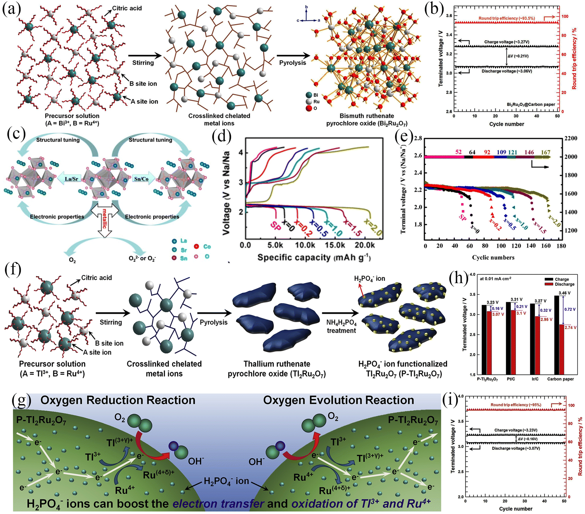 | ||
| Fig. 18 (a) Schematic illustration of the preparation of Bi2Ru2O7. (b) Cycle performance of Bi2Ru2O7-based cathode Na–O2 batteries. (Reproduced from ref. 26 with permission from Elsevier). (c) Schematic illustration tuning the electronic and structural properties via adjusting the element composition of La2Sn2O7. (d) The initial discharge-charge profiles for La2Sn2−xCoxO7 at 100 mA g−1. (e) Cycle performance of La2Sn2−xCoxO7-based cathode Na–O2 batteries at a current density of 200 mA g−1. (Reproduced from ref. 159 with permission from the American Chemical Society). (f) Schematic illustration of the preparation of P-Tl2Ru2O7. (g) Schematic illustration of the catalytic origin of P-Tl2Ru2O7. (h) Comparison of the overpotential of the P-Tl2Ru2O7, Pt/C, Ir/C and carbon paper. (i) Long-term performance of P-Tl2Ru2O7-based cathode Na–O2 batteries. (Reproduced from ref. 162 with permission from Elsevier). | ||
The electronic properties of A2B2O7 can be tailored by substituting metal dopants at the A-site and/or B-site. This would alter the localised electron density, affecting the interaction of the 3d electrons in the metal atoms. Jiang et al.159 studied the role of metal dopant substitutions on the electrocatalytic performance of La2Sn2O7 (Fig. 18c). The impact of the substitution of Sr into La (A site) on the electrochemical properties of pyrochlore oxides was studied. The FTIR and XPS results indicated that by increasing the Sr content in La2−xSrxSn2O7 (x = 0, 0.2, 0.5, 1.0, 1.5, 2.0), the length of Sn–O bond would change, which would promote the movement of oxygen in the catalyst and improve the catalytic activity. When the Sr content is increased to x ≥ 1.5, La2−xSrxSn2O7 exhibits a larger specific surface area, which is also beneficial to improving the catalytic performance. When applied to the cathode of Na–O2 battery, the first discharge-specific capacity of the La2−xSrxSn2O7 catalyst regularly increased with the increase of Sr content. In addition, the change in trend of the catalytic activity of La2Sn2−xCoxO7 (x = 0, 0.2, 0.5, 1.0, 1.5, 2.0) is consistent with that of A-site substituted La2Sn2O7. La2Co2O7 exhibited an extremely high initial discharge specific capacity of 20184.2 mA h g−1 and excellent cycling stability (167 cycles) (Fig. 18d and e). This is due to the generation of oxygen vacancies during the replacement of Sn by Co, resulting in local structural changes. The above results indicate that substituting atoms at different positions can effectively tune the electrocatalytic performance of pyrochlore oxide catalysts. In addition, the limited surface chemical reactions of pyrochlore oxides limit the development of electrocatalytic activity, and therefore surface modification of pyrochlore oxides can significantly improve their electrochemical performance. Kim et al.162 fabricated functionalized pyrochlore oxide (P-Tl2Ru2O7) by modifying P-Tl2Ru2O7 with dihydrogen phosphate ions (H2PO4−) (Fig. 18f), and applied it to the cathode of Na–air battery. After the ORR/OER process, the K-edge X-ray absorption near-edge structure (XANES) spectra of Ru in P- Tl2Ru2O7 and Tl2Ru2O7 shifted to higher photon energies, indicating the oxidation of metallic Ru during the electrochemical process. The LIII-edge XANES spectra of Tl in P-Tl2Ru2O7 and Tl2Ru2O7 also showed the same trend, indicating that the Tl cation showed a higher oxidation state after the ORR/OER process. The H2PO4− ions on the surface of P-Tl2Ru2O7 promoted the oxidation of metal Ru and Tl, which accelerated the electron transfer to the inner layer and surface of the oxide, and further significantly reduced the electrical resistance during electrocatalysis. Meanwhile, the O 2p and Ru 4d orbitals in P-Tl2Ru2O7 are highly hybridized and formed strong Ru–O covalent bonds, which improved the ORR/OER catalytic activity of P-Tl2Ru2O7 (Fig. 18g). In Na–air batteries, the P-Tl2Ru2O7 cathode with excellent electrochemical properties exhibited an overpotential of only 160 mV (Fig. 18h). This P-Tl2Ru2O7 air cathode was stably cycled more than 50 times at a current density of 0.01 mA cm−2 (Fig. 18i). Furthermore, use of different A-site/B-site-cation combinations, cation substitution at different positions, and anion modification methods can help totune the electronic structure of pyrochlore oxides to improve their electrocatalytic performance.
The charging process of Na–O2 batteries is essentially the process of oxygen evolution, which corresponds to the OER catalytic reaction. In this process, the formation of strong O![[double bond, length as m-dash]](https://www.rsc.org/images/entities/char_e001.gif) O covalent bonds is very slow, and high energy is required, which has prompted the search for bifunctional catalysts with excellent catalytic activity.169 Co-based compounds are considered a class of bifunctional catalysts with excellent catalytic properties with examples being NaCoPO4 and Na2CoP2O7.170 Polyanionic framework compounds composed of three-dimensional transition metals exhibit stable crystal structures and are derived from ionic/covalent bonds in three-dimensional frameworks.171–174 Compared to conventional oxides, cobalt-based phosphates have strong phosphate skeletons and diverse structures, which can stabilize the intermediate species in the catalytic center of the catalytic process.169 In 2020, Barpanda et al.163 used a solution combustion method to synthesize porous Na2CoPO4 Fcathodes that exhibited an overpotential of only 417 mV at a current density of 10 μA cm−2, which makes them very promising as a bifunctional cathode for secondary Na–O2 batteries.
O covalent bonds is very slow, and high energy is required, which has prompted the search for bifunctional catalysts with excellent catalytic activity.169 Co-based compounds are considered a class of bifunctional catalysts with excellent catalytic properties with examples being NaCoPO4 and Na2CoP2O7.170 Polyanionic framework compounds composed of three-dimensional transition metals exhibit stable crystal structures and are derived from ionic/covalent bonds in three-dimensional frameworks.171–174 Compared to conventional oxides, cobalt-based phosphates have strong phosphate skeletons and diverse structures, which can stabilize the intermediate species in the catalytic center of the catalytic process.169 In 2020, Barpanda et al.163 used a solution combustion method to synthesize porous Na2CoPO4 Fcathodes that exhibited an overpotential of only 417 mV at a current density of 10 μA cm−2, which makes them very promising as a bifunctional cathode for secondary Na–O2 batteries.
In summary, the essence of Na–air battery cathode material is a bifunctional catalyst with excellent ORR and OER catalytic activities. However, unlike conventional bifunctional catalysts, Na–air battery cathode materials need to have the ability to accommodate discharge products at the same time. An ideal cathode material for air batteries needs to satisfy the following design strategies: (i) excellent electrochemical durability/stability: electrochemical reactions with high chemical/electrochemical stability under charge/discharge and minimal irreversible reactions, improved round-trip efficiency of the battery and maintenance of long-term stability. (ii) Higher specific surface area, which provides abundant active sites: cathode materials with high surface area and mesoscale pores exhibit high NaO2 storage capacity, enhancing the discharge capacity of the battery. A clear correlation has been shown between surface properties such as surface area and mesopore volume of air battery cathode materials and electrochemical properties such as discharge capacity. (iii) Porous structure increases mass transfer during electrochemical processes: electrodes with large pore volume facilitate electrolyte penetration and ensure that the active components (i.e. Na+ and O2) reach the reaction sites. The adequate porosity of air electrodes not only favors the transport and accumulation of discharge products, but also determines the size of the discharge products, while contributing to the cycling stability of the battery. (iv) High conductivity: a high conductivity-air cathode helps electrons to be transferred from the poorly conductive discharge products to the cathode surface with a low overpotential.
4. Metal–air battery: in situ spectroelectrochemical techniques
Metal–air batteries have attracted much attention due to their outstanding specific capacity and energy density. However, the overpotential depends on the discharge products formed during the discharge process, which need to be carefully studied. Therefore, it is necessary to further study the reaction mechanism of Na–air batteries. For example (1) designing a reasonable battery material structure to improve the utilization of catalysts and to guide the distribution of discharge products without blocking the pores. (2) Exploring the factors that affect the type and shape of discharge products and adjusting the influencing factors to effectively control the discharge products and increase the cycle life of batteries. (3) The more reactive metal Na is prone to react with moisture and CO2 in the air. However, trace amounts of water can be used to regulate the electrochemical reaction process and it is currently possible to use an absolutely dry atmosphere for electrochemical reactions. The current research on CO2 removal by metal–organic frameworks with porous structures provides design solutions for removing sufficient CO2 from the air stream.175–177 Therefore, it is of great significance to design and study Na–air batteries that can work in an air atmosphere. (4) Advanced analytical testing methods have been used to reveal the reaction mechanisms between Na and O2. Spectroelectrochemistry can be used to analyze changes in electrochemical cells caused by electrochemical processes. In situ spectroelectrochemical testing can capture in situ generated species by controlling the cell potential to obtain critical information for developing high-performance metal–air batteries. The spectroelectrochemical techniques include in situ infrared spectroscopy, in situ electron spin resonance, in situ UV/Vis spectroscopy, and in situ Raman spectroscopy in this section.4.1. Infrared spectroscopy
The molecules or chemical bonds in a material are in a vibrational state at a temperature above zero Kelvin. Therefore, when the material is irradiated by infrared light, the molecules/chemical bonds produce unique absorption frequencies and can be used to identify their characteristics. Conventional infrared spectrum analysis adopts infrared transmission spectroscopy. The infrared spectrum test of the electrochemical electrode interface is often a reflection method. Common reflectance tests are diffuse reflectance infrared spectroscopy (DRIFTS), attenuated total internal reflection infrared spectroscopy (ATR-IR), and infrared reflectance absorption spectroscopy (IRAS). IRAS technology is currently widely used, but the influence of the absorption of infrared light by the medium passing through it during the test will affect the sensitivity of the electrochemical interface. Although ex situ analysis is more convenient to ensure the accuracy of the results, the sample preparation process for ex situ testing is very cumbersome. For example, the discharge product of organic Na–O2 battery is NaO2, but NaO2 is unstable in air and easily reacts with moisture, oxygen, carbon dioxide, etc. to form products that will affect the accuracy of the results. Therefore, in situ testing can generate more accurate information about reaction products and intermediates.At present, many in situ infrared spectroscopy testing techniques have been successfully applied to metal–air batteries. In 2013, Calvo et al.178 studied the stability of dimethyl sulfoxide (DMSO) in Li–air batteries using in situ infrared spectroscopy and electrochemical experiments. The results of the subtractively normalized interfacial Fourier transform infrared spectroscopy (SNIFTIS) showed no significant changes in the infrared spectra during discharge in oxygen-saturated electrolyte and during charging at 3.0–3.8 V, indicating no change in solvent composition (Fig. 19a). When charged to 4.2 V, new peaks appeared at 1295 cm−1 (SO2 asymmetric stretching vibration) and 1142 cm−1 (SO2 symmetric stretching vibration) and the peak intensity increased significantly with increasing voltage, which was attributed to the generation of dimethyl sulfone (DMSO2) (Fig. 19b). At the same time, a positive peak appeared at 3500 cm−1, which may be assigned to the O–H stretching and was caused by the consumption of trace water. The same phenomenon was also observed in the electrolyte without oxygen (Fig. 19c), indicating that the formation of DMSO2 at high potential is not resulting from the presence of oxygen in the system. Hardwick and co-workers179 also employed in situ ATR-SEIRAS to study the stability of electrolyte solvents in Li–O2 batteries (Fig. 19d). The SEIRAS results showed that propylene carbonate (PC) in the PC-LiClO4 system undergoes a ring-opening reaction to form carbonate (ROCO2Li) species under the applied voltage (Fig. 19e). However, no apparent ring-opening reaction was observed in the PC-TEAClO4 system indicating the significance of the electrolyte solute cations in the stability of PC.
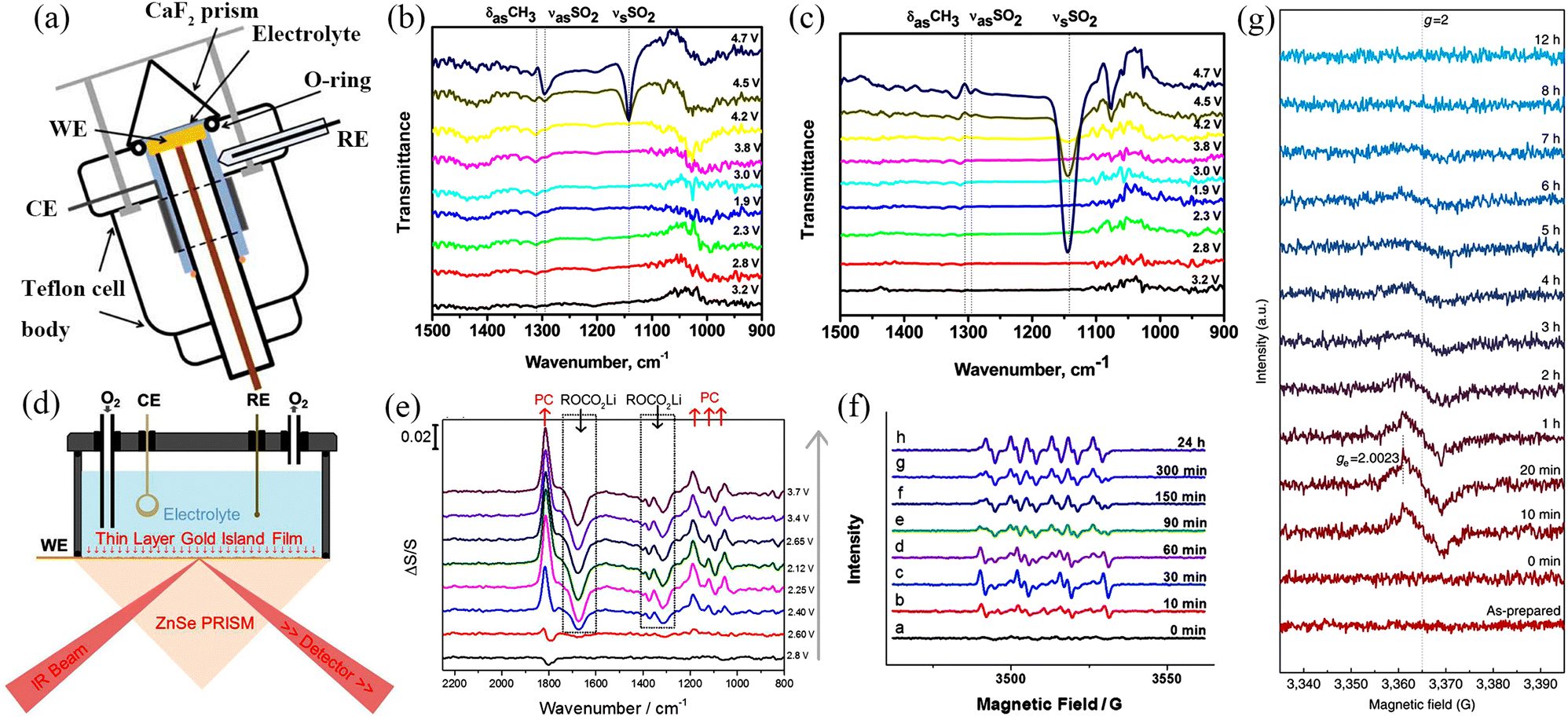 | ||
| Fig. 19 (a) Schematic representation of experimental spectroelectrochemical battery. (Reproduced from ref. 180 with permission from the Electrochemical Society). (b) In situ IR spectra of an O2 saturated solution of 0.1 M TBAPF6 in DMSO. (c) In situ IR spectra of a deoxygenated solution of 0.1 M TBAPF6 in DMSO. (Reproduced from ref. 178 with permission from the American Chemical Society). (d) Schematic of SEIRA spectroelectrochemical cell. (e) The SEIRA spectra result for Au thin film electrode in oxygen saturated 0.1 M LiClO4/PC electrolyte at various electrode potentials. (Reproduced from ref 179 with permission from the American Chemical Society). (f) The ESR spectra of discharged electrolytes at the air electrode side. (Reproduced from ref. 181 with permission from Wiley). (g) The ESR results for the fresh electrolytes with soaking of the pre-discharged cathode without any aging. (Reproduced from ref. 182 with permission from Springer Nature). | ||
4.2. Electron spin resonance
Electron spin resonance (ESR) can quantitatively and qualitatively detect unsaturated electrons in molecules and probe the structural features of their surrounding environment at the same time. ESR equipment for metal–air batteries differs from conventional testing facilities in that the components are housed in cells that can be analyzed by an ESR spectrometer, which detects free radicals generated during charge and discharge, among other products. The research on metal–air batteries has focused on discharge product composition, structure, and morphology. However, the types of intermediates during the charge–discharge process are still unclear. Zhang et al.181 detected the intermediate product of superoxide radical anion (O2˙−) in the ORR process of Li–O2 batteries. Generally, LiO2 and O2˙− are unstable and their existence time in the system is very short, so it is difficult to use ESR in this regard. Therefore, 5,5-dimethyl-pyrroline N-oxide (DMPO) was used as a free radical scavenger to capture O2˙− to form a stable adduct. The long lifetime and stable ESR signal facilitate the study of intermediates in the formation of discharge products. No signal was observed at the initial stage of the discharge process, indicating that no free radicals were generated during this period. The ESR signal gradually increased as the discharge progressed, but the signal began to weaken after 30 min of discharge. When the discharge was continued for 90 min, 6 groups of new signals appeared and the appearance of new signals was attributed to the ORR process that produced O2˙− (Fig. 19f). However, the phenomenon during charging is diametrically opposite to that during discharging and no obvious O2˙− signal is observed. However, a new set of weak signals appeared late in the charging process, which was analysed and found to be caused by free radicals generated by the decomposition of the electrolyte under high pressure. Therefore, it shows that in the Li–O2 battery with DMSO as the electrolyte, the discharge process is dominated by single electron transfer (O2 → O2˙− → O22−) while the charging process involves double electron transfer (O22− → O2), and there is no O2˙− intermediate product.Similarly, Kang et al.182 used ESR to study the dissolution behaviour of NaO2 which is the discharge product of organic Na–O2 batteries (Fig. 19g). The ESR signal was generated after the electrode was soaked in fresh electrolyte for 10 min, indicating the production of O2˙−. The signal intensity of O2˙− reached the highest value after 20 min, followed by a gradual decrease in intensity, and disappeared completely after 8 h of immersion. Combining the above experimental phenomena and literature analysis, it can be concluded that the discharge product NaO2 will dissolve in the ether-based electrolyte to generate O2˙− and Na+. However, due to the poor stability of O2˙−, H+ can be extracted from the electrolyte solvent to form hydroperoxyl radicals (HO2). In the presence of nucleophilic attack of HO2 and oxidation reactions, the electrolyte solvent also decomposes to form carbon dioxide (CO2), water (H2O), and hydroxyl anions (OH−). At the same time, HO2 will undergo a disproportionation reaction to form hydrogen peroxide (H2O2) and O2. The above reactions occur in the same system; Na+, OH− and H2O2 undergo further peroxo-hydroxylation to form Na2O2·2H2O. The decomposition of Na2O2·2H2O requires higher energy, resulting in an increase in the overpotential of Na–O2 batteries. Thus, ESR has shown significant advantages in studying the redox reaction mechanism of metal–air batteries.
4.3. UV/Vis spectroscopy
UV/Vis absorption spectroscopy (UV/Vis spectroscopy) of metal–air batteries has been mainly used to study intermediate products during the charge/discharge process. O2˙− shows strong absorbance at 245 nm in DMSO and 306 nm in pyridine.183 Peroxides do not have this feature and thus the intermediate product conversion process can be studied by UV/Vis spectroscopy. UV/Vis spectroscopy is normally used to study the transition of valence electrons. In metal–O2 batteries, the main research using this technique has focussed on the n → π* and π → π* transitions of O2˙−. The schematic diagram of the in situ UV/Vis device is shown in Fig. 20a, with indium tin oxide as cathode and Li foil as anode, and the device was assembled in a glove box.184 In 2015, Ye et al.185 conducted a detailed study of the ORR/OER process of Li–O2 batteries using in situ UV/Vis spectroscopy. As shown in Fig. 20b, the electrode in the initial state did not have any absorption peak while a strong absorption peak located at 252 nm appeared when discharged to 2.0 V, which was due to the occurrence of 1πu → 1πg transition of O2− in the solvent. Moreover, the peak intensity gradually increased with time, which indicated that O2− was continuously generated during the oxygen reduction process. The absorbance decreased when the charging process was carried out, but the superoxide remained in the solution (Fig. 20c). When the cell voltage was kept at 4.0 V, the absorbance decreased with time, indicating that the oxidation reaction of superoxide was still occurring. In addition, it was proved that LiO2 and Li2O2 were generated during the discharge process by in situ Raman spectroscopy and in situ surface-enhanced Raman vibrational spectroscopy. In conclusion, side reactions on Au electrodes in DMSO solution are ignored in short-term observations. On the one hand, O2− can exist stably and form superoxide in TBAClO4 (Li-free electrolyte)/DMSO solution; On the other hand, when using DMSO solution containing lithium-ions, the ORR process becomes complicated and oxygen is gradually reduced to form LiO2 and Li2O2 on the Au electrode.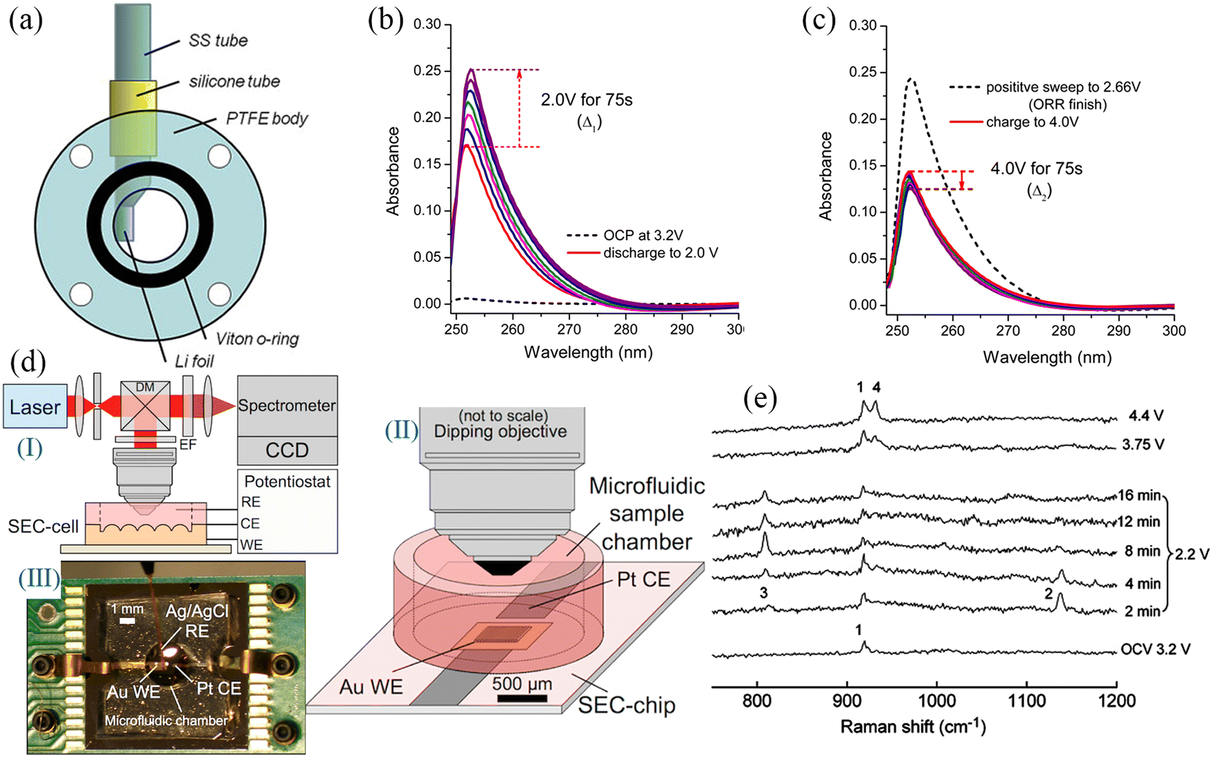 | ||
| Fig. 20 (a) Schematic of in situ UV/Vis spectroscopy battery. (Reproduced from ref. 184 with permission from Elsevier). (b) The UV/Vis spectra of discharge electrode and (c) corresponding spectra of charge electrode in O2-saturated TBAClO4-DMSO. (Reproduced from ref. 185 with permission from the American Chemical Society). (d) In situ SERS spectroelectrochemical analysis system. (I) Schematic of the Raman analysis system. (II) Spectroelectrochemical-cell composed of a spectroelectrochemical-chip directly bonded to a small-volume microfluidic sample chamber with an optical interface to a microscope objective. (III) Spectroelectrochemical cell consisting of a Pt CE and a nanostructured Au WE patterned on the silicon spectroelectrochemical-chip and an external Ag/AgCl RE. (Reproduced from ref. 186 with permission from the American Chemical Society). (e) In situ SERS results during charge and discharge on Au in O2-saturated 0.1M LiClO4-CH3CN. (Reproduced from ref. 187 with permission from Wiley). | ||
4.4. Raman spectroscopy
In situ Raman spectroscopy can be used to study the detailed mechanism of the oxygen cathode interfacial reaction in Na–air batteries and the side reactions in the reaction process, but the Raman signal is often unsatisfactory. Therefore, it is necessary to use a specific method to enhance the Raman signal. First, the method of roughening the electrode surface can be used to obtain surface-enhanced Raman scattering spectroscopy (SERS) with high intensity (Fig. 20d).188–191 If electrochemical Raman spectroscopy is used to study the redox mechanism of metal–air batteries, the gold electrode can be used as the air cathode, which shows a strong SERS signal.192 Shell-isolated nanoparticle-enhanced Raman spectroscopy (SHINERS) can also be employed to meet experimental needs.193 Due to the specific characteristics of metal–air batteries, it is necessary to use in situ Raman spectroscopy, especially for Na- and K-based systems with stronger alkali metal activity, and thus, the accuracy of the results obtained by ex situ techniques needs to be verified. The whole in situ Raman cell device is made of quartz glass and the counter electrode and the reference electrode are sealed in glass capillaries. Bruce and colleagues187 used in situ SERS to provide strong evidence for the redox reaction mechanism of organic Li–O2 batteries (0.1M LiClO4–CH3CN). Only one peak appeared in the open-circuit voltage regime, which was attributed to the C–C symmetric stretching in CH3CN. Two new peaks appeared when discharged to 2.2 V, at 1137 cm−1 and 808 cm−1, which corresponded to the stretching of the O–O bond in LiO2 and the O–O bond in Li2O2, respectively (Fig. 20e). As time increased, the amount of LiO2 gradually decreased, while Li2O2 gradually increased. It has been shown that in the organic electrolyte with lithium ions, the reduction product of O2 first combines with Li+ to form LiO2, and then LiO2 disproportionates to form a more stable Li2O2.
Although various electrochemical testing techniques and phase analysis techniques have been developed, it is difficult for other testing techniques other than spectroelectrochemistry to comprehensively understand electrode reactions or study complex electrode systems. Thus, in situ spectroelectrochemical technology provides a strong technique to support the development of high-performance metal–air batteries and has broad application prospects.
5. Summary and outlook
5.1. Summary
Rechargeable Na–air batteries have received a lot of attention due to their significant energy density and cost advantages. Firstly, the present work summarised the basic working principles of organic Na–air batteries and hybrid Na–air batteries, which is helpful for a more in-depth study of their redox mechanisms. Although there is fierce competition between organic Na–air batteries and hybrid Na–air batteries, the essence of their discharge and charge processes is still the oxygen reduction and evolution processes, respectively. For organic Na–air batteries, the composition and morphology of the discharge products are influenced by various factors (category and surface properties of the air electrode and electrolyte composition). At the same time, the presence of organic electrolytes will result in discharge products with low conductivity and poor solubility to accumulate in the air electrode, covering the active sites, increasing the overpotential during cycling, and reducing the cycle life. In addition, organic electrolytes are expensive, flammable, and quite toxic. Thus the hybrid Na–air battery has received extensive attention due to its simple reaction process, single discharge product, high theoretical operating voltage, and long cycle life.Next, a comprehensive summary has been provided regarding the research progress of air cathodes in Na–air batteries, which considered different material possibilities including carbon materials, transition metals and metal oxides, noble metals, perovskites and spinels, metal–organic frameworks and their derivatives, pyrochlore oxides, and others used to lesser extent. Carbon materials considered including carbon films, CNTs, CNFs, porous carbon spheres, graphene, reduced graphene oxide, and porous carbon. The results show that the content of functional groups on the surface of carbon materials can affect the morphology and types of discharge products. At the same time, carbon cathodes with abundant pores are more easily wet by the electrolyte, which will enure full use of the abundant redox sites and enable the accommodation of more discharge products to increase cycle stability and life. Carbon cathodes are the most promising commercial air cathode materials. In addition to the above carbon-based materials with bright application prospects, transition metal-based electrocatalysts with enhanced electrochemical performance are also included, including CoB, CoP, SnS2, CoO, Co3O4, Mn2O3, α-MnO2, VO2@rGO–carbon paper and Co@ECNCFs. Noble metals have received extensive attention because of their electrocatalytic reaction kinetics and improved catalytic activity since they can improve the interfacial interactions of reactants. RuO2 nanoparticles dispersed on the surface of CNT, Pt clusters deposited on the surface of defective NiFe LDHs, Ru dispersed on the surface of CNTs, Ag nanoparticles modified rGO, and Pd nanoparticles grown on ZnO can all be used as Na–O2 battery cathode materials. Ternary metal oxides with oxygen vacancies and crystal defects exhibit more prominent catalytic activity in comparison to binary metal oxides. Additionally, defect engineering (such as A-site/B-site substitution, oxygen vacancy and anion doping) can be employed to introduce defects in metal oxides to increase the ORR/OER activity significantly. Both pristine MOFs and MOF derivatives can exhibit excellent electrochemical performance, which arises because the MOFs assembled by metal nodes and organic ligands has a porous network structure and endows the material with a large specific surface area, which is conducive to the contact, transport and exchange of the material, and ensures the continuous reactions as part of the oxygen reduction and oxygen evolution processes.
At the same time, it is necessary to use in situ spectroelectrochemical technologies (such as IR, ESR, UV/Vis Spectroscopy and Raman Spectroscopy) to monitor the intermediate products during the charging and discharging process of Na–air batteries to reveal the mechanisms related to the formation and disappearance of the discharge products, as well as the generation of side products.
6. Outlook
Na-air batteries show advantages such as low overpotential and high theoretical specific capacity and energy density, but not very obvious advantages in terms of cycling performances since side reactions on the air cathode, metal Na cathode and electrolyte limit the cycle life of Na–air batteries. Thus, there are still many challenges and possible future research directions for Na–air batteries in order to ensure their commercialization (Fig. 21).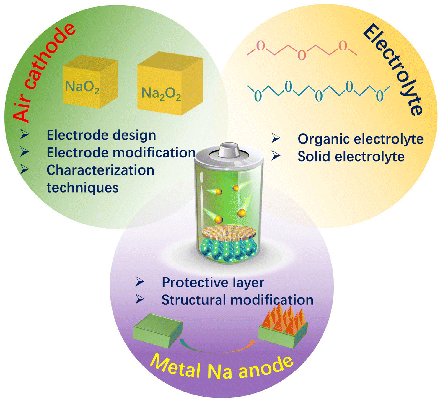 | ||
| Fig. 21 The major challenges facing the development of Na–air batteries. | ||
(1) Air cathode: The electrochemical performance of Na–air batteries depend largely on the electrochemical performance of the air cathode. During the discharge process, the internal pores of the air cathode material will be gradually filled with solid discharge products, which will block O2 diffusion and electrolyte transfer, leading to a decrease in discharge specific capacity. At the same time, the accumulation of insoluble discharge products during the deep discharge process will cause the volume expansion of the air cathode material. Due to the mutual support of discharge products and cathode material, the whole electrode structure will not change significantly. However, after the discharge products are dissolved in the subsequent charging process, the conductive electrode material connectivity of the air cathode will inevitably become reduced, which would lead to irreversible breakage of the electrode structure. Therefore, the ideal air cathode should have the following characteristics: high surface area with porous structure, high electrical conductivity, effective catalytic activity to facilitate ORR and OER processes, and sufficient mechanical strength and stability for accommodating the volume expansion during the formation and decomposition of insoluble discharge products. In this direction, current efforts should be devoted to the discovery and design of suitable anode materials, such as multidimensional nanostructured carbon materials, metal nanoparticles, transition metal oxides, perovskite/spinel oxides, and metal–organic frameworks to improve the cycle specific capacity, energy density, and cycle life of Na–air batteries. Taking perovskite/spinel oxides with excellent catalytic activity as an example, perovskite and spinel phase with excellent electrocatalytic properties, have potential for very broad application prospects in rechargeable Na–air batteries. Moreover, defect engineering can be used to enahnce the catalytic activity of perovskite and spinel. Further, combining advanced characterization techniques with simulation is necessary to systematically study the effect of defect engineering on catalytic activity. Importantly, a large amount of research is currently devoted to studying how the physicochemical properties of air cathodes affect the composition (i.e. NaO2, Na2O2 or Na2O2·2H2O) and morphology of discharge products. Carbon cathodes with abundant pores and high specific surfaces are currently the most promising commercial cathodes. However, the mechanism of the formation and growth of different discharge products with different morphologies on electrodes is still unclear. To develop a more stable air cathode, various in situ and ex situ characterization techniques are needed to reveal the correlation between the discharge products and the properties of the air cathode. At the same time, to study more diverse and complex processes, a variety of in situ spectroelectrochemical techniques can be employed.
(2) Na anode: In order to improve the energy density of Na–air battery, the direct use of Na metal is beneficial to maximise the actual energy density of the battery. The metal anode loses electrons during the discharge process to form Na+, which diffuses through the electrolyte to the cathode side of the battery to form discharge products. During the charging process, the metal ions are deposited on the electrode surface by reduction, and their morphology is different from the initial shape. The potential gradient between the cathode and anode leads to the formation of sodium dendrites. After many charge/discharge cycles, sodium dendrites pose a serious risk to the operation of the actual battery. Once the dendrites keep growing and completely penetrate the diaphragm, the battery may fail due to short circuit between the cathode and the anode. Adding a protective layer to the sodium metal surface is a very common strategy to reduce dendrite formation for higher cycling stability, and the protective layer can consist of a polymer solid electrolyte. The protective layer must meet the following criteria: (1) high ionic conductivity to promote uniform sodium ion transport across the electrode surface; (2) high hardness, elastic modulus, and compact structure to inhibit dendrite formation; (3) sufficient flexibility to accommodate interfacial fluctuations during sodium precipitation/deposition; and (4) capability to prevent oxygen and moisture crossover between the air electrode and the sodium anode. In addition to the above methods, the metal Na anode can be modified to reduce dendrite formation. The use of pre-sodiumed hard carbon and/or hollow carbon spheres as anode material can largely reduce the formation of dendrites and improve the cycle life of the battery. However, such a measure will reduce the weight of sodium metal in the anode material and reduce the energy density of the battery.
(3) Advances in situ/operando characterization technologies combined with theoretical models: Elucidating the cause of poor results using conventional ex situ characterization techniques often requires the disassembly of metal–air batteries after operation. Samples can often be contaminated during disassembly. In contrast, in situ/operational microscopy and spectroscopy combined with first-principles density functional theory (DFT) calculations can capture dynamic information during cycling, enabling real-time monitoring of the processes in the metal–air battery. These techniques also promise to illustrate what can be gained from in situ/operational characterization techniques and serves as a reference for research into other battery types. At present, many in situ infrared spectroscopy testing techniques have been successfully applied to metal–air batteries, for instance: in situ ATR-SEIRAS to study the stability of electrolyte solvents in Li–O2 batteries, as well as in situ interfacial Fourier transform infrared spectroscopy (SNIFTIS), in situ IR spectra, in situ UV/Vis, in situ Raman spectroscopy and in situ surface-enhanced Raman vibrational spectroscopy. First-principles calculation methods based on DFT and molecular dynamics method (MD) have attracted much attention. Computational simulations can predict correlations between material properties, including phase stability, lithium diffusion behavior, interface formation energy and electrode/electrolyte interface reactions. This can reduce research time and cost. Combining in situ/operational characterization techniques with computational simulations can provide insight into reaction mechanisms. The obtained characterization data can also be used to verify the accuracy of computational simulations and guide the establishment of new models and the development of new methods.
(4) Electrolyte: In addition to the imporatnt air cathode and metal Na anode, the effect of the type of electrolyte, modification and addition of additives has a significant effect on the specific capacity and cycle life of Na–air batteries. It is well known that carbonate-based electrolytes are prone to decomposition forming by-products during cycling, so ether-based electrolytes with better stability are used. However, the safety and environmentally-friendly nature of organic electrolytes is yet to be resolved. It is very promising to select solid electrolytes with high ionic conductivity to assemble a solid-state secondary Na–air battery or to fabricate hybrid Na–air batteries. For hybrid Na–air batteries, using aqueous electrolytes as the cathode compartment electrolyte can reduce the overpotential and improve the cycle life. However, designing and producing NASICON separators with higher ionic conductivity may become a bottleneck for large-scale production of hybrid Na–air batteries.
List of acronyms and abbreviations
| H2PO4− | Dihydrogen phosphate ions |
| A2B2O7 | Pyrochlore oxide |
| AB2O4 | Spinel oxides |
| ABO3 | Perovskite oxides |
| ABO3−δ | Defective perovskite oxides |
| ALD | Atomic layer deposition |
| ATR-IR | Attenuated total internal reflection infrared spectroscopy |
| ATR-SEIRAS | Attenuated total reflectance surface enhanced infrared absorption spectroscopy |
| C@NiCo2O4-NAs | Sea urchin-like C@NiCo2O4 nanoneedles |
| CNF | Carbon nanofibers |
| CNT | Carbon nanotube |
| Co–Fe@NC | Nitrogen-doped carbon-coated CoFe bimetallic nanoparticles |
| Co–N–C | Co nanoparticles-modified N-doped defect carbon framework |
| Co-PBA | Co-based Prussian blue analogs |
| DEGDME | Diethylene glycol dimethyl ether |
| DFT | First-principles calculations |
| DME | Dimethyl ether |
| DMPO | 5,5-Dimethyl-pyrroline N-oxide |
| DMSO | Dimethyl sulfoxide |
| DMSO2 | Dimethyl sulfone |
| DRIFTS | Diffuse reflectance infrared spectroscopy |
| ESR | Electron spin resonance |
| Fe-NiCoP | Fe-doped NiCoP |
| Fe-NiCoP@C | Carbon coating Fe-NiCoP |
| GO | Graphene oxide |
| h-Co3O4@MnCo2O4.5 | Ns Hierarchical Co3O4@MnCo2O4.5 nanocubes |
| IRAS | Infrared reflectance absorption spectroscopy |
| IVCT | Intervalence charge transfer |
| KO2 | Potassium superoxide |
| LAB | Lithium–air battery |
| LDH | Layered double hydroxide |
| LIBs | Lithium-ion batteries |
| LSV | Linear cyclic voltammetry |
| MOF-NCNFs | Nitrogen-doped carbon nanotubes |
| MOFs | Metal–organic frameworks |
| m-RuO2-B-rGO | Microscale RuO2-coated rGO composites |
| MWNTs | Multi-walled carbon nanotubes |
| Na2CO3 | Sodium carbonate |
| Na2O2 | Sodium peroxide |
| NaClO4 | Sodium perchlorate |
| NaO2 | Sodium superoxide |
| NaPF6 | Sodium hexafluorophosphate |
| NASICON | Na3Zr2Si2PO12 |
| NaSO3CF3 | Sodium trifluoromethyl sulfonate |
| NaTFSI | Sodium bis(trifluoromethanesulfonyl)imide |
| NC | Nitrogen-doped carbon |
| NCF | Nitrogen atoms into carbon nanofibers derived from polypyrrole |
| OER | Oxygen evolution reaction |
| ORR | Oxygen reduction reaction |
| PCS | Porous carbon spheres |
| Pt/NixFe-LDHs | Defect-layered double hydroxide nanosheets |
| P-Tl2Ru2O7 | Modifying P-Tl2Ru2O7 with H2PO4− |
| SABs | Sodium–air batteries |
| SEI | Solid electrolyte layer |
| SEM | Scanning electron microscopy |
| SERS | Surface-enhanced Raman scattering spectroscopy |
| SHINERS | Shell-isolated nanoparticles-enhanced Raman spectroscopy |
| SIBs | Sodium-ion batteries |
| SNIFTIS | Subtractively normalized interfacial Fourier transform infrared spectroscopy |
| TEGDME | Triethylene glycol dimethyl ether |
| TiOSO4 | Titanium oxysulfate |
| TMs | Transition metals |
| TMOs | Transition metal oxide |
| VGC | VO2@rGO/carbon paper |
| XANES | X-ray absorption near-edge structure |
| XAS | X-ray absorption spectroscopy |
| XPS | X-ray photoelectron spectroscopy |
| XRD | X-ray diffraction |
| ZIF-67 | Cobalt 2-methylimidazole |
Author contributions
Pengcheng Mao: investigation, formal analysis, writing – original draft, writing – review & editing. Hamidreza Arandiyan: conceptualization, investigation, methodology, supervision, writing – original draft, writing – review & editing. Sajjad S. Mofarah: methodology, investigation, formal analysis, writing – review & editing. Pramod Koshy: methodology, investigation, formal analysis, writing – review & editing. Cristina Pozo-Gonzalo: methodology, investigation, resources, formal analysis, writing – review & editing. Runguo Zheng: methodology, investigation, formal analysis. Zhiyuan Wang: methodology, investigation, formal analysis. Suresh K. Bhargava: methodology, investigation, formal analysis, writing – review & editing. Yuan Wang: conceptualization, investigation, methodology, resources, supervision, writing – original draft, writing – review & editing. Hongyu Sun: conceptualization, investigation, methodology, supervision, writing – original draft, writing – review & editing. Zongping Shao: methodology, writing – review & editing. Yanguo Liu: methodology, investigation, resources, supervision, writing – review & editing.Conflicts of interest
There are no conflicts to declare.Acknowledgements
H. Sun and Y. Liu acknowledge funding from the National Natural Science Foundation of China (52171202, 52177208, 51971055). Yuan Wang acknowledges the financial support by the Alfred Deakin Postdoctoral Research Fellowship 2022 (PJ08390) by Deakin University. Cristina Pozo-Gonzalo acknowledges the support by the Australian Research Council Training Centre for Future Energy Storage Technologies (IC180100049), funded by the Australian Government. H. Arandiyan and S. Bhargava acknowledge financial support from the Queensland Pacific Metals (QPM).References
- R. Bird, Z. J. Baum, X. Yu and J. Ma, ACS Energy Lett., 2022, 7, 736–740 CrossRef CAS.
- J. Li and X.-G. Sun, Chem, 2021, 7, 1705–1707 CAS.
- M. Li, J. Lu, Z. Chen and K. Amine, Adv. Mater., 2018, 30, 1800561 CrossRef PubMed.
- T. Hosaka, K. Kubota, A. S. Hameed and S. Komaba, Chem. Rev., 2020, 120, 6358–6466 CrossRef CAS PubMed.
- H. Zhao, W.-Y. A. Lam, L. Wang, H. Xu, W. A. Daoud and X. He, Energy Environ. Sci., 2022, 15, 2329–2355 RSC.
- J. Mao, C. Ye, S. Zhang, F. Xie, R. Zeng, K. Davey, Z. Guo and S. Qiao, Energy Environ. Sci., 2022, 15, 2732–2752 RSC.
- J. C. Stallard, L. Wheatcroft, S. G. Booth, R. Boston, S. A. Corr, M. F. L. De Volder, B. J. Inkson and N. A. Fleck, Joule, 2022, 6, 984–1007 CrossRef CAS.
- Y. Liu, H. Zhang, N. Jiang, W. Zhang, H. Arandiyan, Z. Wang, S. Luo, F. Fang and H. Sun, J. Alloys Compd., 2020, 834, 155030 CrossRef CAS.
- P. Mao, H. Fan, G. Zhou, H. Arandiyan, C. Liu, G. Lan, Y. Wang, R. Zheng, Z. Wang, S. K. Bhargava, H. Sun and Y. Liu, J. Colloid Interface Sci., 2023, 634, 63–73 CrossRef CAS PubMed.
- H. Fan, C. Liu, G. Lan, P. Mao, R. Zheng, Z. Wang, Y. Liu and H. Sun, Electrochim. Acta, 2023, 439, 141614 CrossRef CAS.
- Z. Zheng, J. Jiang, H. Guo, C. Li, K. Konstantinov, Q. Gu and J. Wang, Nano Energy, 2021, 81, 105529 CrossRef CAS.
- L. Zhang, Q. Zhuang, R. Zheng, Z. Wang, H. Sun, H. Arandiyan, Y. Wang, Y. Liu and Z. Shao, Energy Storage Mater., 2022, 49, 299–338 CrossRef.
- H.-F. Wang and Q. Xu, Matter, 2019, 1, 565–595 CrossRef CAS.
- X. Lin, J. Wang, X. Gao, S. Wang, Q. Sun, J. Luo, C. Zhao, Y. Zhao, X. Yang, C. Wang, R. Li and X. Sun, Chem. Mater., 2020, 32, 3018–3027 CrossRef CAS.
- J. Wang, R. Gao, L. Zheng, Z. Chen, Z. Wu, L. Sun, Z. Hu and X. Liu, ACS Catal., 2018, 8, 8953–8960 CrossRef CAS.
- C. Murugesan, S. P. Panjalingam, S. Lochab, R. K. Rai, X. Zhao, D. Singh, R. Ahuja and P. Barpanda, Nano Energy, 2021, 89, 106485 CrossRef CAS.
- Y. Kang, S. Wang, S. Zhu, H. Gao, K. S. Hui, C.-Z. Yuan, H. Yin, F. Bin, X.-L. Wu, W. Mai, L. Zhu, M. Hu, F. Liang, F. Chen and K. N. Hui, Appl. Catal., B, 2021, 285, 119786 CrossRef CAS.
- X. Jin, Y. Li, S. Zhang, J. Zhang, Z. Shen, C. Zhong, Z. Cai, C. Hu and H. Zhang, Chin. Chem. Lett., 2022, 33, 491–496 CrossRef CAS.
- K. M. Abraham and Z. Jiang, J. Electrochem. Soc., 1996, 143, 1–5 CrossRef CAS.
- L.-N. Song, W. Zhang, Y. Wang, X. Ge, L.-C. Zou, H.-F. Wang, X.-X. Wang, Q.-C. Liu, F. Li and J.-J. Xu, Nat. Commun., 2020, 11, 2191 CrossRef CAS PubMed.
- X. Shen, S. Zhang, Y. Wu and Y. Chen, ChemSusChem, 2019, 12, 104–114 CrossRef CAS PubMed.
- Z. Zheng, C. Wu, Q. Gu, K. Konstantinov and J. Wang, Energy Environ. Mater., 2021, 4, 158–177 CrossRef CAS.
- P. Shen, B. Zhang, Y. Wang, X. Liu, C. Yu, T. Xu, S. S. Mofarah, Y. Yu, Y. Liu, H. Sun and H. Arandiyan, J. Nanostruct. Chem., 2021, 11, 33–68 CrossRef.
- H. Fan, P. Mao, H. Sun, Y. Wang, S. S. Mofarah, P. Koshy, H. Arandiyan, Z. Wang, Y. Liu and Z. Shao, Mater. Horiz., 2022, 9, 524–546 RSC.
- H. Yadegari and X. Sun, Trends Chem., 2020, 2, 241–253 CrossRef CAS.
- M. Kim, H. Ju and J. Kim, Chem. Eng. J., 2019, 358, 11–19 CrossRef CAS.
- J.-L. Ma, F.-L. Meng, D. Xu and X.-B. Zhang, Energy Storage Mater., 2017, 6, 1–8 CrossRef.
- Q. Sun, Y. Yang and Z.-W. Fu, Electrochem. Commun., 2012, 16, 22–25 CrossRef CAS.
- J. Chen, B. Zhang, L. Qian, H. Wan, T. Yu, Z. Wei, Z. Wang, S. Luo, H. Arandiyan, Y. Liu and H. Sun, J. Alloys Compd., 2021, 850, 156858 CrossRef CAS.
- E. Peled, D. Golodnitsky, H. Mazor, M. Goor and S. Avshalomov, J. Power Sources, 2011, 196, 6835–6840 CrossRef CAS.
- J.-l Ma, W.-c Zhang, X.-d Wang, M. Tang, Z.-y Huang, J. Li, H. Zhang, X.-h Yang, Z.-p Guo and Y. Wang, Nano Energy, 2021, 84, 105927 CrossRef CAS.
- P. Hartmann, C. L. Bender, M. Vračar, A. K. Dürr, A. Garsuch, J. Janek and P. Adelhelm, Nat. Mater., 2013, 12, 228–232 CrossRef CAS PubMed.
- B. Sun, C. Pompe, S. Dongmo, J. Zhang, K. Kretschmer, D. Schröder, J. Janek and G. Wang, Adv. Mater. Technol., 2018, 3, 1800110 CrossRef.
- C. L. Bender, D. Schröder, R. Pinedo, P. Adelhelm and J. Janek, Angew. Chem., Int. Ed., 2016, 55, 4640–4649 CrossRef CAS PubMed.
- S. M. B. Khajehbashi, L. Xu, G. Zhang, S. Tan, Y. Zhao, L.-S. Wang, J. Li, W. Luo, D.-L. Peng and L. Mai, Nano Lett., 2018, 18, 3934–3942 CrossRef CAS PubMed.
- W.-J. Kwak, L. Luo, H.-G. Jung, C. Wang and Y.-K. Sun, ACS Energy Lett., 2018, 3, 393–399 CrossRef CAS.
- T. A. Ha, C. Pozo-Gonzalo, K. Nairn, D. R. MacFarlane, M. Forsyth and P. C. Howlett, Sci. Rep., 2020, 10, 7123 CrossRef CAS PubMed.
- Y. Zhang, N. Ortiz-Vitoriano, B. Acebedo, L. O’Dell, D. R. MacFarlane, T. Rojo, M. Forsyth, P. C. Howlett and C. Pozo-Gonzalo, J. Phys. Chem. C, 2018, 122, 15276–15286 CrossRef CAS.
- T. Wang, Y. Han, P. Xu, X. Feng, W. Ji and H. Arandiyan, Chem. Eng. J., 2022, 138245, DOI:10.1016/j.cej.2022.138245.
- J. Kim, H.-D. Lim, H. Gwon and K. Kang, Phys. Chem. Chem. Phys., 2013, 15, 3623–3629 RSC.
- L. Lutz, D. Alves Dalla Corte, M. Tang, E. Salager, M. Deschamps, A. Grimaud, L. Johnson, P. G. Bruce and J.-M. Tarascon, Chem. Mater., 2017, 29, 6066–6075 CrossRef CAS.
- M. Balaish, A. Kraytsberg and Y. Ein-Eli, Phys. Chem. Chem. Phys., 2014, 16, 2801–2822 RSC.
- Z. Khan, M. Vagin and X. Crispin, Adv. Sci., 2020, 7, 1902866 CrossRef CAS PubMed.
- C. Xu, K. Zhang, D. Zhang, S. Chang, F. Liang, P. Yan, Y. Yao, T. Qu, J. Zhan, W. Ma, B. Yang, Y. Dai and X. Sun, Nano Energy, 2020, 68, 104318 CrossRef CAS.
- X. Xu, K. S. Hui, D. A. Dinh, K. N. Hui and H. Wang, Mater. Horiz., 2019, 6, 1306–1335 RSC.
- Y. Zhou, F. Chen, H. Arandiyan, P. Guan, Y. Liu, Y. Wang, C. Zhao, D. Wang and D. Chu, J. Energy Chem., 2021, 57, 516–542 CrossRef CAS.
- M. Enterría, M. Reynaud, J. I. Paredes, L. Medinilla, R. Younesi and N. Ortiz-Vitoriano, J. Energy Chem., 2022, 68, 709–720 CrossRef.
- X. Li, Z. Zhang, M. Shen, Z. Wang, R. Zheng, H. Sun, Y. Liu, D. Wang and C. Liu, J. Colloid Interface Sci., 2022, 628, 242–251 CrossRef CAS PubMed.
- C. Duan, X. Li, D. Wang, Z. Wang, H. Sun, R. Zheng and Y. Liu, Sustainable Energy Fuels, 2022, 6, 1479–1488 RSC.
- Y. Li, H. Yadegari, X. Li, M. N. Banis, R. Li and X. Sun, Chem. Commun., 2013, 49, 11731–11733 RSC.
- W. Liu, Q. Sun, Y. Yang, J.-Y. Xie and Z.-W. Fu, Chem. Commun., 2013, 49, 1951–1953 RSC.
- Z. Jian, Y. Chen, F. Li, T. Zhang, C. Liu and H. Zhou, J. Power Sources, 2014, 251, 466–469 CrossRef CAS.
- W.-J. Kwak, Z. Chen, C. S. Yoon, J.-K. Lee, K. Amine and Y.-K. Sun, Nano Energy, 2015, 12, 123–130 CrossRef CAS.
- Q. Sun, H. Yadegari, M. N. Banis, J. Liu, B. Xiao, B. Wang, S. Lawes, X. Li, R. Li and X. Sun, Nano Energy, 2015, 12, 698–708 CrossRef CAS.
- C. L. Bender, P. Hartmann, M. Vračar, P. Adelhelm and J. Janek, Adv. Energy Mater., 2014, 4, 1301863 CrossRef.
- S. Kang, Y. Mo, S. P. Ong and G. Ceder, Nano Lett., 2014, 14, 1016–1020 CrossRef CAS PubMed.
- B. Lee, J. Kim, G. Yoon, H.-D. Lim, I.-S. Choi and K. Kang, Chem. Mater., 2015, 27, 8406–8413 CrossRef CAS.
- P. Hartmann, M. Heinemann, C. L. Bender, K. Graf, R.-P. Baumann, P. Adelhelm, C. Heiliger and J. Janek, J. Phys. Chem. C, 2015, 119, 22778–22786 CrossRef CAS.
- J. E. Nichols and B. D. McCloskey, J. Phys. Chem. C, 2017, 121, 85–96 CrossRef CAS.
- C. Xia, R. Black, R. Fernandes, B. Adams and L. F. Nazar, Nat. Chem., 2015, 7, 496–501 CrossRef CAS PubMed.
- M. S. Jung, S. Ha, D. Koo and K. T. Lee, J. Phys. Chem. C, 2020, 124, 7644–7651 CrossRef CAS.
- N. Ortiz-Vitoriano, T. P. Batcho, D. G. Kwabi, B. Han, N. Pour, K. P. C. Yao, C. V. Thompson and Y. Shao-Horn, J. Phys. Chem. Lett., 2015, 6, 2636–2643 CrossRef CAS PubMed.
- Y. Hu, X. Han, Q. Zhao, J. Du, F. Cheng and J. Chen, J. Mater. Chem. A, 2015, 3, 3320–3324 RSC.
- L. Lutz, D. A. D. Corte, Y. Chen, D. Batuk, L. R. Johnson, A. Abakumov, L. Yate, E. Azaceta, P. G. Bruce, J.-M. Tarascon and A. Grimaud, Adv. Energy Mater., 2018, 8, 1701581 CrossRef.
- F. Wu, Y. Xing, J. Lai, X. Zhang, Y. Ye, J. Qian, L. Li and R. Chen, Adv. Funct. Mater., 2017, 27, 1700632 CrossRef.
- M. Fathi Tovini, M. Hong, J. Park, M. Demirtaş, D. Toffoli, H. Ustunel, H. R. Byon and E. Yılmaz, J. Phys. Chem. C, 2018, 122, 19678–19686 CrossRef CAS.
- F. Liang and K. Hayashi, J. Electrochem. Soc., 2015, 162, A1215–A1219 CrossRef CAS.
- S. Park, Z. Khan, T. J. Shin, Y. Kim and H. Ko, J. Mater. Chem. A, 2019, 7, 1564–1573 RSC.
- J. Mei, T. Liao, J. Liang, Y. Qiao, S. X. Dou and Z. Sun, Adv. Energy Mater., 2020, 10, 1901997 CrossRef CAS.
- D. Cao, Y. Bai, J. Zhang, G. Tan and C. Wu, Nano Energy, 2021, 89, 106464 CrossRef CAS.
- H. Yadegari, M. N. Banis, B. Xiao, Q. Sun, X. Li, A. Lushington, B. Wang, R. Li, T.-K. Sham, X. Cui and X. Sun, Chem. Mater., 2015, 27, 3040–3047 CrossRef CAS.
- N. Zhao, C. Li and X. Guo, Phys. Chem. Chem. Phys., 2014, 16, 15646–15652 RSC.
- H. Yadegari, C. J. Franko, M. N. Banis, Q. Sun, R. Li, G. R. Goward and X. Sun, J. Phys. Chem. Lett., 2017, 8, 4794–4800 CrossRef CAS PubMed.
- N. Ortiz-Vitoriano, I. Monterrubio, L. Garcia-Quintana, J. M. López del Amo, F. Chen, T. Rojo, P. C. Howlett, M. Forsyth and C. Pozo-Gonzalo, ACS Energy Lett., 2020, 5, 903–909 CrossRef CAS.
- C. Shu, Y. Lin, B. Zhang, S. B. Abd Hamid and D. Su, J. Mater. Chem. A, 2016, 4, 6610–6619 RSC.
- B. Sun, K. Kretschmer, X. Xie, P. Munroe, Z. Peng and G. Wang, Adv. Mater., 2017, 29, 1606816 CrossRef PubMed.
- M. Enterría, C. Botas, J. L. Gómez-Urbano, B. Acebedo, J. M. López del Amo, D. Carriazo, T. Rojo and N. Ortiz-Vitoriano, J. Mater. Chem. A, 2018, 6, 20778–20787 RSC.
- S. Zhang, Z. Wen, J. Jin, T. Zhang, J. Yang and C. Chen, J. Mater. Chem. A, 2016, 4, 7238–7244 RSC.
- J.-l Ma and X.-b Zhang, J. Mater. Chem. A, 2016, 4, 10008–10013 RSC.
- L. Ma, J. Li, H. Arandiyan, W. Shi, C. Liu and L. Fu, Catal. Today, 2012, 184, 145–152 CrossRef CAS.
- H. Li, T. A. Ha, N. Ortiz-Vitoriano, X. Wang, J. Fang, P. C. Howlett and C. Pozo-Gonzalo, J. Mater. Chem. A, 2022, 10, 11742–11754 RSC.
- J.-l Ma, N. Li, Q. Zhang, X.-b Zhang, J. Wang, K. Li, X.-f Hao and J.-m Yan, Energy Environ. Sci., 2018, 11, 2833–2838 RSC.
- Z. Khan, N. Parveen, S. A. Ansari, S. T. Senthilkumar, S. Park, Y. Kim, M. H. Cho and H. Ko, Electrochim. Acta, 2017, 257, 328–334 CrossRef CAS.
- Q. Sun, J. Liu, X. Li, B. Wang, H. Yadegari, A. Lushington, M. N. Banis, Y. Zhao, W. Xiao, N. Chen, J. Wang, T.-K. Sham and X. Sun, Adv. Funct. Mater., 2017, 27, 1606662 CrossRef.
- N. Li, D. Xu, D. Bao, J. Ma and X. Zhang, Chin. J. Catal., 2016, 37, 1172–1179 CrossRef CAS.
- N. Parveen, Z. Khan, S. A. Ansari, S. Park, S. T. Senthilkumar, Y. Kim, H. Ko and M. H. Cho, Chem. Eng. J., 2019, 360, 415–422 CrossRef CAS.
- S. Rosenberg and A. Hintennach, J. Power Sources, 2015, 274, 1043–1048 CrossRef CAS.
- Z. Khan, B. Senthilkumar, S. O. Park, S. Park, J. Yang, J. H. Lee, H.-K. Song, Y. Kim, S. K. Kwak and H. Ko, J. Mater. Chem. A, 2017, 5, 2037–2044 RSC.
- Y. J. Sa, K. Kwon, J. Y. Cheon, F. Kleitz and S. H. Joo, J. Mater. Chem. A, 2013, 1, 9992–10001 RSC.
- Y. Liang, Y. Li, H. Wang, J. Zhou, J. Wang, T. Regier and H. Dai, Nat. Mater., 2011, 10, 780–786 CrossRef CAS PubMed.
- X.-d Wang, X. Zhang, M. Tang, Q.-y Shen and J.-l Ma, J. Alloys Compd., 2021, 882, 160702 CrossRef CAS.
- Z. Khan, S. Park, S. M. Hwang, J. Yang, Y. Lee, H.-K. Song, Y. Kim and H. Ko, NPG Asia Mater., 2016, 8, e294–e294 CrossRef.
- W.-M. Liu, W.-W. Yin, F. Ding, L. Sang and Z.-W. Fu, Electrochem. Commun., 2014, 45, 87–90 CrossRef CAS.
- Y. Kang, D. Zou, J. Zhang, F. Liang, K. Hayashi, H. Wang, D. Xue, K. Chen, K. R. Adair and X. Sun, Electrochim. Acta, 2017, 244, 222–229 CrossRef CAS.
- Y. Liu, X. Chi, Q. Han, Y. Du, J. Yang and Y. Liu, J. Alloys Compd., 2019, 772, 693–702 CrossRef CAS.
- A. Hu, C. Shu, C. Xu, R. Liang, J. Li, R. Zheng, M. Li and J. Long, J. Mater. Chem. A, 2019, 7, 21605–21633 RSC.
- C. Shu, C. Wu, J. Long, H. Guo, S.-X. Dou and J. Wang, Nano Energy, 2019, 57, 166–175 CrossRef CAS.
- X. Yu, J. Guo, B. Li, J. Xu, P. Gao, K. S. Hui, K. N. Hui and H. Shao, ACS Appl. Mater. Interfaces, 2021, 13, 26891–26903 CrossRef CAS PubMed.
- J.-H. Kang, W.-J. Kwak, D. Aurbach and Y.-K. Sun, J. Mater. Chem. A, 2017, 5, 20678–20686 RSC.
- S. Kumar, B. Kishore and N. Munichandraiah, RSC Adv., 2016, 6, 63477–63479 RSC.
- L. Ma, D. Zhang, Y. Lei, Y. Yuan, T. Wu, J. Lu and K. Amine, ACS Energy Lett., 2018, 3, 276–277 CrossRef CAS.
- S. Zhang, Z. Wen, K. Rui, C. Shen, Y. Lu and J. Yang, J. Mater. Chem. A, 2015, 3, 2568–2571 RSC.
- M. F. Tovini, B. Patil, C. Koz, T. Uyar and E. Yılmaz, Nanotechnology, 2018, 29, 475401 CrossRef PubMed.
- X. Yu, Y. Kang, S. Wang, K. S. Hui, K. N. Hui, H. Zhao, J. Li, B. Li, J. Xu, L. Chen and H. Shao, J. Mater. Chem. A, 2020, 8, 16355–16365 RSC.
- S. Angel, J. Neises, M. Dreyer, K. Friedel Ortega, M. Behrens, Y. Wang, H. Arandiyan, C. Schulz and H. Wiggers, AIChE J., 2020, 66, e16748 CrossRef CAS.
- Y. Wang, X. Shen, H. Arandiyan, Y. Yin, F. Sun, X. Chen, M. Garbrecht, L. Han, G. G. Andersson and C. Zhao, J. Power Sources, 2020, 478, 228748 CrossRef CAS.
- S. Angel, J. Neises, M. Dreyer, K. Friedel Ortega, M. Behrens, Y. Wang, H. Arandiyan, C. Schulz and H. Wiggers, AIChE J., 2020, 66, e16748 CrossRef CAS.
- Y. Wang, H. Arandiyan, J. Scott, H. Dai and R. Amal, Adv. Sustainable Syst., 2018, 2, 1700119 CrossRef.
- N. Habibi, Y. Wang, H. Arandiyan and M. Rezaei, ChemCatChem, 2016, 8, 3600–3610 CrossRef CAS.
- H. Arandiyan, Y. Wang, H. Sun, M. Rezaei and H. Dai, Chem. Commun., 2018, 54, 6484–6502 RSC.
- S. C. Tidrow, Ferroelectrics, 2014, 470, 13–27 CrossRef CAS.
- Q. Ji, L. Bi, J. Zhang, H. Cao and X. S. Zhao, Energy Environ. Sci., 2020, 13, 1408–1428 RSC.
- J. Li, K. He, Q. Meng, X. Li, Y. Zhu, S. Hwang, K. Sun, H. Gan, Y. Zhu, Y. Mo, E. A. Stach and D. Su, ACS Nano, 2016, 10, 9577–9585 CrossRef CAS PubMed.
- P. Liu, Y. Liao, J. Li, L. Chen, M. Fu, P. Wu, R. Zhu, X. Liang, T. Wu and D. Ye, J. Colloid Interface Sci., 2021, 594, 713–726 CrossRef CAS PubMed.
- Y. Wang, H. Arandiyan, J. Scott, H. Dai and R. Amal, Adv. Sustainable Syst., 2018, 1700119, DOI:10.1002/adsu.201700119.
- Y. Wang, H. Arandiyan, X. Chen, T. Zhao, X. Bo, Z. Su and C. Zhao, J. Phys. Chem. C, 2020, 124, 9971–9978 CrossRef CAS.
- M. T. Le, P. A. Nguyen, T. T. H. Tran, T. H. N. Chu, Y. Wang and H. Arandiyan, Top. Catal., 2022, 66, 117–125 CrossRef.
- H. Arandiyan, S. S. Mofarah, C. C. Sorrell, E. Doustkhah, B. Sajjadi, D. Hao, Y. Wang, H. Sun, B.-J. Ni, M. Rezaei, Z. Shao and T. Maschmeyer, Chem. Soc. Rev., 2021, 50, 10116–10211 RSC.
- H. Arandiyan, S. S. Mofarah, Y. Wang, C. Cazorla, D. Jampaiah, M. Garbrecht, K. Wilson, A. F. Lee, C. Zhao and T. Maschmeyer, Chem. – Eur. J., 2021, 27, 14418–14426 CrossRef CAS PubMed.
- Y. S. Kim, G.-H. Lee, M.-C. Sung and D.-W. Kim, Chem. Eng. J., 2021, 406, 126896 CrossRef CAS.
- M. Xu, X. Hou, X. Yu, Z.-F. Ma, J. Yang and X. Yuan, J. Electrochem. Soc., 2019, 166, F406–F413 CrossRef CAS.
- J. G. Kim, Y. Noh, Y. Kim, S. Lee and W. B. Kim, Nanoscale, 2017, 9, 5119–5128 RSC.
- Q. Zhao, Z. Yan, C. Chen and J. Chen, Chem. Rev., 2017, 117, 10121–10211 CrossRef CAS PubMed.
- J. Béjar, L. Álvarez-Contreras, J. Ledesma-García, N. Arjona and L. G. Arriaga, J. Mater. Chem. A, 2020, 8, 8554–8565 RSC.
- X. Han, H. Sheng, C. Yu, T. W. Walker, G. W. Huber, J. Qiu and S. Jin, ACS Catal., 2020, 10, 6741–6752 CrossRef CAS.
- Q. Sun, X. Lin, H. Yadegari, W. Xiao, Y. Zhao, K. R. Adair, R. Li and X. Sun, J. Mater. Chem. A, 2018, 6, 1473–1484 RSC.
- H. Wang, X. Chen, D. Huang, M. Zhou, D. Ding and H. Luo, ChemCatChem, 2020, 12, 2768–2775 CrossRef CAS.
- W. Xu, N. Apodaca, H. Wang, L. Yan, G. Chen, M. Zhou, D. Ding, P. Choudhury and H. Luo, ACS Catal., 2019, 9, 5074–5083 CrossRef CAS.
- X. Liu, L. Zhang, Y. Zheng, Z. Guo, Y. Zhu, H. Chen, F. Li, P. Liu, B. Yu, X. Wang, J. Liu, Y. Chen and M. Liu, Adv. Sci., 2019, 6, 1801898 CrossRef PubMed.
- S. She, J. Yu, W. Tang, Y. Zhu, Y. Chen, J. Sunarso, W. Zhou and Z. Shao, ACS Appl. Mater. Interfaces, 2018, 10, 11715–11721 CrossRef CAS PubMed.
- A. Ashok, A. Kumar, J. Ponraj, S. A. Mansour and F. Tarlochan, Catal. Today, 2021, 375, 484–493 CrossRef CAS.
- Y. Zhang, F. Feng, C. Zhang, Q. Zheng, C. Wang, H. Hu, M. Wu and Y. Guo, Energy Fuels, 2020, 34, 10170–10177 CrossRef CAS.
- J. Suntivich, H. A. Gasteiger, N. Yabuuchi, H. Nakanishi, J. B. Goodenough and Y. Shao-Horn, Nat. Chem., 2011, 3, 546–550 CrossRef CAS PubMed.
- Y. Lv, Z. Li, Y. Yu, J. Yin, K. Song, B. Yang, L. Yuan and X. Hu, J. Alloys Compd., 2019, 801, 19–26 CrossRef CAS.
- Y. Zhu, W. Zhou, J. Yu, Y. Chen, M. Liu and Z. Shao, Chem. Mater., 2016, 28, 1691–1697 CrossRef CAS.
- H. Lee, O. Gwon, C. Lim, J. Kim, O. Galindev and G. Kim, ChemElectroChem, 2019, 6, 3154–3159 CrossRef CAS.
- J.-I. Jung, H. Y. Jeong, J.-S. Lee, M. G. Kim and J. Cho, Angew. Chem., Int. Ed., 2014, 53, 4582–4586 CrossRef CAS PubMed.
- K. Lopez, G. Park, H. J. Sun, J. C. An, S. Eom and J. Shim, J. Appl. Electrochem., 2015, 45, 313–323 CrossRef CAS.
- K. Li, M. Yin, Z. Wang, X. Chen, T. Zhu, J. Wang, N. Dewangan, Y. Yu, Q. Zhong and S. Kawi, ChemistrySelect, 2018, 3, 12424–12429 CrossRef CAS.
- J. Ran, T. Wang, J. Zhang, Y. Liu, C. Xu, S. Xi and D. Gao, Chem. Mater., 2020, 32, 3439–3446 CrossRef CAS.
- Z. Li, L. Lv, J. Wang, X. Ao, Y. Ruan, D. Zha, G. Hong, Q. Wu, Y. Lan, C. Wang, J. Jiang and M. Liu, Nano Energy, 2018, 47, 199–209 CrossRef CAS.
- Q. A. Islam, R. Majee and S. Bhattacharyya, J. Mater. Chem. A, 2019, 7, 19453–19464 RSC.
- L. Gui, Z. Wang, K. Zhang, B. He, Y. Liu, W. Zhou, J. Xu, Q. Wang and L. Zhao, Appl. Catal., B, 2020, 266, 118656 CrossRef CAS.
- J. Cheng, Z. Wang, L. Zou, M. Zhang, G. Zhang, Y. Dong, Y. Jiang, Y. Huang, N. Nakashima and B. Chi, J. Alloys Compd., 2020, 831, 154728 CrossRef CAS.
- J. Zhou and B. Wang, Chem. Soc. Rev., 2017, 46, 6927–6945 RSC.
- P. Mao, G. Lan, C. Liu, Z. Wang, Y. Liu, H. Sun and W. Huang, SM&T, 2021, 30, e00354 Search PubMed.
- P. Mao, H. Fan, C. Liu, G. Lan, W. Huang, Z. Li, H. Mahmoud, R. Zheng, Z. Wang, H. Sun and Y. Liu, Sustainable Energy Fuels, 2022, 6, 4075–4084 RSC.
- B. Zhu, Z. Liang, D. Xia and R. Zou, Energy Storage Mater., 2019, 23, 757–771 CrossRef.
- Y. Wang, B. Liu, X. Shen, H. Arandiyan, T. Zhao, Y. Li, M. Garbrecht, Z. Su, L. Han, A. Tricoli and C. Zhao, Adv. Energy Mater., 2021, 2003759 CrossRef CAS.
- A. Wang, H. Niu, X. Wang, X. Wan, L. Xie, Z. Zhang, J. Wang and Y. Guo, J. Mater. Chem. A, 2022, 10, 13005–13012 RSC.
- J. Chen, H. Li, C. Fan, Q. Meng, Y. Tang, X. Qiu, G. Fu and T. Ma, Adv. Mater., 2020, 32, 2003134 CrossRef CAS PubMed.
- Y. Kang, S. Wang, K. S. Hui, H. F. Li, F. Liang, X. L. Wu, Q. Zhang, W. Zhou, L. Chen, F. Chen and K. N. Hui, Mater. Today Energy, 2021, 20, 100572 CrossRef.
- Y. Wu, X. Qiu, F. Liang, Q. Zhang, A. Koo, Y. Dai, Y. Lei and X. Sun, Appl. Catal., B, 2019, 241, 407–414 CrossRef CAS.
- J. Zhu, T. Qu, F. Su, Y. Wu, Y. Kang, K. Chen, Y. Yao, W. Ma, B. Yang, Y. Dai, F. Liang and D. Xue, Dalton Trans., 2020, 49, 1811–1821 RSC.
- H. Gao, S. Zhu, Y. Kang, D. A. Dinh, K. S. Hui, F. Bin, X. Fan, F. Chen, A. Mahmood, J. Geng, W.-C. M. Cheong and K. N. Hui, ACS Appl. Energy Mater., 2022, 5, 1662–1671 CrossRef CAS.
- Y. Liu, X. Chi, Q. Han, Y. Du, J. Huang, X. Lin and Y. Liu, Nanoscale, 2019, 11, 5285–5294 RSC.
- X. Yang, F. Su, M. Hou, D. Zhang, Y. Dai and F. Liang, Dalton Trans., 2021, 50, 7041–7047 RSC.
- W. Y. Noh, E. M. Kim, K. Y. Kim, J. H. Kim, H. Y. Jeong, P. Sharma, G. Lee, J.-W. Jang, S. H. Joo and J. S. Lee, J. Mater. Chem. A, 2020, 8, 18891–18902 RSC.
- N. Li, Y. Yin, F. Meng, Q. Zhang, J. Yan and Q. Jiang, ACS Catal., 2017, 7, 7688–7694 CrossRef CAS.
- M. Kim, H. Ju and J. Kim, Dalton Trans., 2018, 47, 15217–15225 RSC.
- M. Kim, H. Ju and J. Kim, J. Mater. Chem. A, 2018, 6, 8523–8530 RSC.
- M. Kim, H. Ju and J. Kim, Appl. Catal., B, 2019, 245, 29–39 CrossRef CAS.
- L. Sharma, R. Gond, B. Senthilkumar, A. Roy and P. Barpanda, ACS Catal., 2020, 10, 43–50 CrossRef CAS.
- B. Senthilkumar, A. Irshad and P. Barpanda, ACS Appl. Mater. Interfaces, 2019, 11, 33811–33818 CrossRef CAS PubMed.
- B. Senthilkumar, Z. Khan, S. Park, I. Seo, H. Ko and Y. Kim, J. Power Sources, 2016, 311, 29–34 CrossRef CAS.
- J. Shamblin, M. Feygenson, J. Neuefeind, C. L. Tracy, F. Zhang, S. Finkeldei, D. Bosbach, H. Zhou, R. C. Ewing and M. Lang, Nat. Mater., 2016, 15, 507–511 CrossRef CAS PubMed.
- J. Park, M. Risch, G. Nam, M. Park, T. J. Shin, S. Park, M. G. Kim, Y. Shao-Horn and J. Cho, Energy Environ. Sci., 2017, 10, 129–136 RSC.
- J. Parrondo, M. George, C. Capuano, K. E. Ayers and V. Ramani, J. Mater. Chem. A, 2015, 3, 10819–10828 RSC.
- H. Kim, J. Park, I. Park, K. Jin, S. E. Jerng, S. H. Kim, K. T. Nam and K. Kang, Nat. Commun., 2015, 6, 8253 CrossRef CAS PubMed.
- R. Gond, K. Sada, B. Senthilkumar and P. Barpanda, ChemElectroChem, 2018, 5, 153–158 CrossRef CAS.
- C. Delacourt, P. Poizot, J.-M. Tarascon and C. Masquelier, Nat. Mater., 2005, 4, 254–260 CrossRef CAS.
- C. Masquelier and L. Croguennec, Chem. Rev., 2013, 113, 6552–6591 CrossRef CAS PubMed.
- E. Doustkhah, H. Mohtasham, M. Farajzadeh, S. Rostamnia, Y. Wang, H. Arandiyan and M. H. N. Assadi, Microporous Mesoporous Mater., 2020, 293, 109832 CrossRef CAS.
- H. Arandiyan, H. Chang, C. Liu, Y. Peng and J. Li, J. Mol. Catal. A: Chem., 2013, 378, 299–306 CrossRef CAS.
- H. Arandiyan, K. Kani, Y. Wang, B. Jiang, J. Kim, M. Yoshino, M. Rezaei, A. E. Rowan, H. Dai and Y. Yamauchi, ACS Appl. Mater. Interfaces, 2018, 10, 24963–24968 CrossRef CAS PubMed.
- Y. Wang, H. Arandiyan, S. A. Bartlett, A. Trunschke, H. Sun, J. Scott, A. F. Lee, K. Wilson, T. Maschmeyer, R. Schlögl and R. Amal, Appl. Catal., B, 2020, 277, 119029 CrossRef CAS.
- C. Jia, S. Li, Y. Zhao, R. K. Hocking, W. Ren, X. Chen, Z. Su, W. Yang, Y. Wang, S. Zheng, F. Pan and C. Zhao, Adv. Funct. Mater., 2021, 31, 2107072 CrossRef CAS.
- N. Mozhzhukhina, L. P. Méndez De Leo and E. J. Calvo, J. Phys. Chem. C, 2013, 117, 18375–18380 CrossRef CAS.
- J. P. Vivek, N. Berry, G. Papageorgiou, R. J. Nichols and L. J. Hardwick, J. Am. Chem. Soc., 2016, 138, 3745–3751 CrossRef CAS PubMed.
- N. Mozhzhukhina, A. Y. Tesio, L. P. M. De Leo and E. J. Calvo, J. Electrochem. Soc., 2017, 164, A518–A523 CrossRef CAS.
- R. Cao, E. D. Walter, W. Xu, E. N. Nasybulin, P. Bhattacharya, M. E. Bowden, M. H. Engelhard and J.-G. Zhang, ChemSusChem, 2014, 7, 2436–2440 CrossRef CAS PubMed.
- J. Kim, H. Park, B. Lee, W. M. Seong, H.-D. Lim, Y. Bae, H. Kim, W. K. Kim, K. H. Ryu and K. Kang, Nat. Commun., 2016, 7, 10670 CrossRef CAS PubMed.
- D. S. Shin, N. Doddapaneni and S. M. Park, Inorg. Chem., 1992, 31, 4060–4064 CrossRef CAS.
- I. Landa-Medrano, M. Olivares-Marín, R. Pinedo, I. Ruiz de Larramendi, T. Rojo and D. Tonti, Electrochem. Commun., 2015, 59, 24–27 CrossRef CAS.
- Q. Yu and S. Ye, J. Phys. Chem. C, 2015, 119, 12236–12250 CrossRef CAS.
- T. Yuan, L. Le Thi Ngoc, J. van Nieuwkasteele, M. Odijk, A. van den Berg, H. Permentier, R. Bischoff and E. T. Carlen, Anal. Chem., 2015, 87, 2588–2592 CrossRef CAS PubMed.
- Z. Peng, S. A. Freunberger, L. J. Hardwick, Y. Chen, V. Giordani, F. Bardé, P. Novák, D. Graham, J.-M. Tarascon and P. G. Bruce, Angew. Chem., Int. Ed., 2011, 50, 6351–6355 CrossRef CAS PubMed.
- L. Johnson, C. Li, Z. Liu, Y. Chen, S. A. Freunberger, P. C. Ashok, B. B. Praveen, K. Dholakia, J.-M. Tarascon and P. G. Bruce, Nat. Chem., 2014, 6, 1091–1099 CrossRef CAS PubMed.
- I. M. Aldous and L. J. Hardwick, Angew. Chem., Int. Ed., 2016, 55, 8254–8257 CrossRef CAS PubMed.
- J. Wang, Y. Zhang, L. Guo, E. Wang and Z. Peng, Angew. Chem., Int. Ed., 2016, 55, 5201–5205 CrossRef CAS PubMed.
- J. Staszak-Jirkovský, R. Subbaraman, D. Strmcnik, K. L. Harrison, C. E. Diesendruck, R. Assary, O. Frank, L. Kobr, G. K. H. Wiberg, B. Genorio, J. G. Connell, P. P. Lopes, V. R. Stamenkovic, L. Curtiss, J. S. Moore, K. R. Zavadil and N. M. Markovic, ACS Catal., 2015, 5, 6600–6607 CrossRef.
- J. T. Frith, A. E. Russell, N. Garcia-Araez and J. R. Owen, Electrochem. Commun., 2014, 46, 33–35 CrossRef CAS.
- T. A. Galloway and L. J. Hardwick, J. Phys. Chem. Lett., 2016, 7, 2119–2124 CrossRef CAS PubMed.
| This journal is © The Royal Society of Chemistry 2023 |