 Open Access Article
A medical waste X-ray film based triboelectric nanogenerator for self-powered devices, sensors, and smart buildings†
M.
Navaneeth
 a,
Supraja
Potu
 a,
Anjaly
Babu
 a,
Rakesh Kumar
Rajaboina
 *a,
Uday Kumar
K
 a,
Haranath
Divi
 a,
Prakash
Kodali
 b and
Balaji
K.
c
aDepartment of Physics, Energy Materials and Devices Lab, National Institute of Technology-Warangal, India-506004. E-mail: rakeshr@nitw.ac.in
bDepartment of Electronics and Communication Engineering, Flexible Electronics Lab, National Institute of Technology-Warangal, India-506004
cSchool of Physics, University of Hyderabad, Hyderabad, Telangana 500046, India
First published on 4th April 2023
Abstract
The increase of plastic waste on the Earth and its associated environmental pollution is a major concern for humankind. The reuse of plastic waste for energy harvesting not only reduces environmental pollution but also generates electricity. In this study, we have used medical plastic waste, such as X-ray films, to fabricate a triboelectric nanogenerator (TENG) for the first time. The proposed TENG produced an output voltage, current, and instantaneous power density of 201 V, 62.8 μA, and 1.39 W m−2, respectively. It can easily power up 240 red LEDs directly and other portable electronic devices with a charged capacitor. The fabricated TENG was further used as a smart switch in selecting various services provided in smart buildings (hospitals/hotels). Additionally, we were able to create self-powered indicator displays and force sensors through this technology. The current results highlight the potential of using medical waste to create energy-harvesting devices and suggest that this approach can be extended to utilize other plastic waste materials such as saline bottles and gloves for TENGs.
Environmental significanceThe proposed work utilized discarded X-ray (plastic) films in energy harvesting devices, which reduces plastic waste dumping. Furthermore, the energy produced by a discarded X-ray film based nanogenerator is utilized in potential applications for powering electronic devices, sensors, and smart homes. |
1 Introduction
Over the years, there has been a surge in plastic waste accumulation on Earth, resulting in severe pollution of water, air, and soil. Reports indicate that about half of the plastic produced ends up in landfills or natural surroundings.1,2 By 2050, plastic waste is projected to outweigh fish due to its constant growth, insufficient recycling mechanisms, and rapid disposal.3 To combat plastic pollution and its climate impact, it is essential to explore alternative ways of utilizing plastic waste.4–6 The world's current energy demand is increasing, which has led to increased environmental pollution from using fossil fuels for electricity production. However, reusing plastic waste for energy generation offers a solution to both electricity generation and environmental pollution reduction. There are various alternative ways of utilizing plastic waste that can help reduce pollution and its impact on the environment. One approach is to recycle plastic waste and use it to manufacture new products7–10 and new functional materials.11–14 Another option is to convert plastic waste into fuel through a process called pyrolysis.15 In addition to the above, plastic waste can also be used to generate energy through triboelectric nanogenerator technology, which is a promising new technology that harnesses the power of friction to generate electricity. This technology utilizes plastic materials to create an active triboelectric layer that can produce electrical energy through contact electrification and electrostatic induction.16 By utilizing plastic waste as an energy source, we can reduce the need for fossil fuels and decrease their impact on the environment while providing a sustainable source of energy for the growing global population.The triboelectric nanogenerator (TENG) technology has evolved for electrical energy generation using plastic materials from the last decade.17–20 Many plastic materials such as PET, PTFE, PS, PVC and PES have been used as active triboelectric layers in TENG device fabrication and utilized for self-powered device applications.21,22 Furthermore, TENGs were developed with different waste materials for energy generation, and we named them W-TENGs.
Table 1 summarizes the literature review of various W-TENGs that have been reported based on different waste materials. These materials include both bio-waste and everyday household waste. The bio-waste materials include peanut shells,23 sunflower husks,24 eggshells,25 rice husks,26 and fish bladder.27 Household waste includes plastic bags,28 food packaging covers,29 rubber tire powder,30 and milk cartons.31 The development of W-TENGs using a range of waste materials shows the potential for creating sustainable energy sources. So far, the highest power density of W-TENGs obtained is 5.33 W m−2 for bio-waste peanut shells. However, no studies have been conducted on TENGs fabricated from medical waste. The medical waste includes plastic syringes, barrels, surgical and handling gloves, plastic saline bottles, X-ray, CT, and MRI sheets. In this study, discarded X-ray sheets were used for TENG fabrication, with a silicone film as the opposite triboelectric layer. We have used discarded X-ray sheets after basic cleaning to remove dust. The obtained power density of the X-ray sheet-based TENG (X-TENG) is 1.39 W m−2, which is in the same order as the reported values in the literature. The advantage of using X-ray films in the TENG with other materials is that no further processing, such as film preparation is required to fabricate the TENG. Waste X-ray films are safe to handle compared to other medical waste, such as gloves, facemasks, PPE kits and saline tubes, which have a high degree of contamination.
| S. no | Waste material | Opposite triboelectric layer | Voltage, current, and power density | Applications | Stability cycles | Ref. |
|---|---|---|---|---|---|---|
| 1 | Polyvinyl chloride (PVC) | Nylon | 31 V, 3.1 μA and 11.9 mW m−2 | Self-powered Morse code generator | 10![[thin space (1/6-em)]](https://www.rsc.org/images/entities/char_2009.gif) 000 000 |
32 |
| 2 | Waste plastic bags | Polytetrafluoroethylene (PTFE) | 251 V, 34.1 μA and power 1.74 W m−2 | Self-powered pencil-on-paper strain sensor | — | 28 |
| 3 | Waste food packaging and aluminum cover foil | Parafilm | 4 V and 118 μW m−2 | Self-powered portable electronic devices and LEDs | 1500 | 29 |
| 4 | Waste tea leaves and packaging bags | Polytetrafluoroethylene (PTFE) | 792 V, 42.8 μA, and 4.88 W m−2 | Powering electronic office supplies | 10![[thin space (1/6-em)]](https://www.rsc.org/images/entities/char_2009.gif) 000 000 |
33 |
| 5 | Aloe vera | Polydimethylsiloxane (PDMS) | 32 V and 0.11 μA and 1.9 mW m−2 | Self-powered finger monitoring sensor | 2500 | 34 |
| 6 | Biowaste peanut shell | Polyethylene terephthalate (PET) | 910 V, 104.5 μA, and a power of 5.33 W m−2 | Self-powered devices | — | 23 |
| 7 | Bio-waste sunflower husks | Polyethylene terephthalate (PET) | 488 V, 28.5 μA, and a power of 0.48 W m−2 | Self-powered devices | — | 24 |
| 8 | Egg shell | Polytetrafluoroethylene (PTFE) | 924 V, 1.3 μA and 0.25 W m−2 | Self-powered wristwatch | — | 25 |
| 9 | Bacterial cellulose | Teflon | 57.6 V, 5.78 μA and 43 mW m−2 | — | 1000 | 35 |
| 10 | Fish bladder film | Fluorinated ethylene propylene (FEP) | 106 V, 7.3 μA and 200 mW m−2 | Smart electronic skin-based wearable electronics | 850 | 27 |
| 11 | Rice husks | Polytetrafluoroethylene (PTFE) | 190 V, 1 μA and 0.12 W m−2 | Power source for LEDs | — | 26 |
| 12 | Rice paper | Polyvinyl chloride (PVC) | 244 V, 6 μA and 376.4 mW m−2 | Power source for LEDs | 10![[thin space (1/6-em)]](https://www.rsc.org/images/entities/char_2009.gif) 000 000 |
36 |
| 13 | Aluminum recyclable paper (ARP) for electrodes | Pt/PET | 3.12 V, 82.8 nA and 3.54 mW m−2 | — | — | 37 |
| 14 | Waste rubber powder | Aluminum | 100 V, 5.5 mA m−2, and 68 mW m−2 | Self-powered electronics | 5000 | 38 |
| 15 | Fluorinated wasted rubber powder (WRP) | Aluminum | 265 V, 75 mA m−2, and 4.6 W m−2 | Self-powered electronics | — | 38 |
| 16 | Recycled plastic bags | Nylon | 35.7 V, 1.56 μA and 152.6 mW m−2 | Integration with supercapacitors for powering LEDs | — | 6 |
| 17 | Plastic waste and carbon-coated paper wipes | Polytetrafluoroethylene (PTFE) | 3.5 μA and power of 0.24 W m−2 | 9-Segment keyboard | 1000 | 39 |
| 18 | Waste milk carton | Polyethylene (PE) | 600 V, 40 μA, and 55.9 mW m−2 | Power wireless sensor for environmental monitoring | 65![[thin space (1/6-em)]](https://www.rsc.org/images/entities/char_2009.gif) 000 000 |
31 |
| 19 | Waste polystyrene | PTFE | 250 V, 52 μA and 4.05 W m−2 | Vehicle speed monitoring sensor | 20![[thin space (1/6-em)]](https://www.rsc.org/images/entities/char_2009.gif) 000 000 |
40 |
| 20 | Recycled plastic and electronic wastes | Chart paper | 83.88 V, 101 μA and 265 mW m−2 | Self-powered portable electronics | 5000 | 41 |
| 21 | Aseptic carton package | Oxidised low-density polyethylene | 200 V, 400 nA | Power source for LEDs | 97![[thin space (1/6-em)]](https://www.rsc.org/images/entities/char_2009.gif) 000 000 |
42 |
| 22 | Discarded plastic waste | PTFE | 3.5 μA, 0.61 mW | Self-powered keyboard and wearable electronics | — | 43 |
| 23 | Surgical face mask | Waste Mylar | 200 V, 0.29 mA m−2, 71.16 mW m−2 | Self-powered watches and calculators | 10![[thin space (1/6-em)]](https://www.rsc.org/images/entities/char_2009.gif) 000 000 |
44 |
| 24 | Nylon(polyamides) | PMMA | 35.7 V, 5.85 μA, 152.6 mW m−2 | Antitheft warning device | 3000 | 45 |
| 25 | Household plastic waste | PU foam | 44 V, 289 nA | Self-powered LED display | 3000 | 46 |
| 26 | Scrap paper | PTFE | 205 V, 18 μA | Human physiological monitoring | 1100 | 47 |
| 27 | X-ray sheets | Silicone | 201 V, 62.8 μA, 1.39 W m −2 | Self-powered devices, force sensors, LEDs, and smart buildings |
10![[thin space (1/6-em)]](https://www.rsc.org/images/entities/char_2009.gif) 000 000 |
Present work |
The present investigation introduces high-performance TENGs that utilize discarded X-ray sheets and silicone as frictional layers for the first time. The TENGs were analyzed for their output current, voltage, power, and stability. The study also examined the impact of varying device dimensions, frequencies of applied force, and magnitudes of applied force on the TENG's performance. The X-TENG was implemented in various applications, including smart switches in buildings, self-powered direction indicator displays with LEDs, self-powered force sensors, and self-powered devices.
2 Experimental details
2.1 Materials and characterization
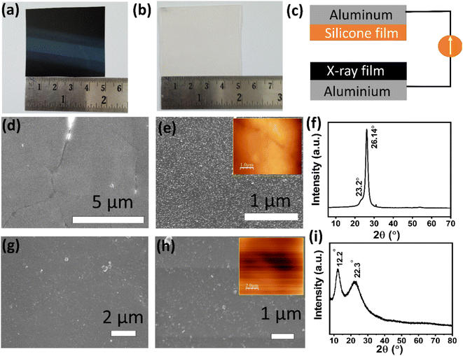
Discarded X-ray films were obtained from a local hospital, cleaned with DI water, and dried. Silicone sheets of 1 mm thickness were purchased from Amazon India. Fig. 1(a) and (b) show the photographs of the X-ray and silicon sheets of 5 × 5 cm2 area. The obtained films were characterized using a field emission scanning electron microscope (FESEM, ZEISS), X-ray diffraction (XRD, Bruker), and an atomic force microscope (AFM, HITACHI).2.2 X-TENG device fabrication and testing
Fig. 1(c) displays the schematic view of the X-TENG device, and the fabrication process involved in fabricating the device is illustrated in Fig. S1 in the ESI, Section S1.† The X-TENG device was constructed using X-ray and silicone sheets as frictional layers with an active device area of 5 × 5 cm2. These sheets were attached to aluminum foil electrodes (∼80 μm thickness) using conducting carbon tape. Two electrical wires connected the top and bottom aluminum electrodes to record the X-TENG response. The X-TENG performance was evaluated in vertical contact separation mode with hand-slapping force, and its electrical outputs were measured using a digital storage oscilloscope (Tektronix, TBS-1102) and a low noise current pre-amplifier SR 570 (Stanford Research Systems) for open-circuit voltage (Voc) and short circuit current (Isc), respectively. The X-TENG's long-term stability and durability were tested over 10![[thin space (1/6-em)]](https://www.rsc.org/images/entities/char_2009.gif) 000 test cycles and three months.
000 test cycles and three months.
2.3 Application of X-TENGs with energy management circuits and digital design boards
To showcase the various applications of X-TENGs, we utilized several electronic components, including a DB 107 full-wave rectifier IC, an IC 74163 binary counter, junction and Zener diodes, a digital circuits development platform (Scientech 2614), and a custom-designed switched-capacitor-convertor circuit.48. The schematic and design of the switched-capacitor-convertor circuit can be found in Fig. S2 in the ESI, Section S2.†3 Results and discussion
Low and high magnification FESEM images of the X-ray sheet surface are presented in Fig. 1(d) and (e). The surface of the X-ray sheet is covered with fine particles, resulting in nanoscale roughness. The RMS roughness of the X-ray sheet surface was determined from the AFM image in the inset of Fig. 1(e) and found to be approximately 28 nm.The XRD pattern of the X-ray sheet is shown in Fig. 1(f), and it matches the XRD pattern reported in the literature for polyethylene terephthalate (PET) sheets.49,50 Therefore, we can infer that the X-ray sheet is a chemically modified PET sheet. The diffraction maximum located at 26.1° is assigned to the (1 0 0) plane and is consistent with the reported literature.
The FESEM images of the silicone sheet surface are further depicted in Fig. 1(g) and (h), which show that it also has roughness at the nanoscale. The RMS roughness of the silicone sheet surface was measured from the AFM image displayed in the inset of Fig. 1(h) and found to be approximately 44 nm. The XRD pattern of the silicone sheet is presented in Fig. 1(i), which matches the silicone rubber XRD pattern documented in the literature.51–53 The diffraction maxima at 22.3° and 12.2° are attributed to the –Si–O–Si– amorphous phase and the polyurea units, respectively.
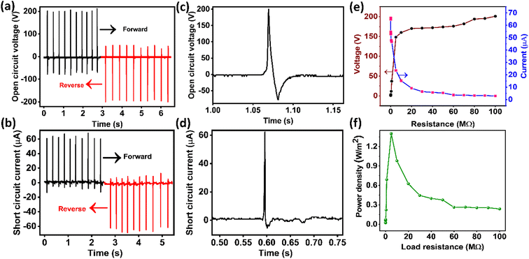
Fig. 2(a) and (b) display the recorded responses (Voc, Isc) of the X-TENG against repeated hand slapping force. The Voc and Isc values of the TENG device are approximately ∼201 V and ∼62.8 μA, respectively. The electrical outputs were measured as part of the switching polarity test to confirm that the electrical outputs originated from the X-TENG device and not from measuring device noise.54Fig. 2(c) and (d) show magnified views of the Voc and Isc of the X-TENG response in one complete cycle. Asymmetry in the positive and negative peaks (current/voltage) is attributed to the difference in the time durations of the contact and separation process, as suggested by the reported literature.55–58 In the present report, the contact process is performed by tapping force, whereas the separation process is due to the elasticity of sponge spacers. Therefore, the contact and separation processes take different time durations. Due to differences in the duration of the contact and separation processes, the rate of charge transfer may vary, resulting in the observed asymmetry in voltage and current signals. Although this phenomenon is consistently observed in most literature reports, a more comprehensive study is necessary to fully comprehend the asymmetry.
As shown in Fig. 2(e), the voltage and current of the X-TENG device were measured under different load resistance (RL) values to study its instantaneous output power. As shown in Fig. 2(e), the output voltage increased while the output current decreased with increasing load resistance. The instantaneous power density (Pd) was obtained from the load characteristic data and plotted in Fig. 2(f). The Pd of the X-TENG initially increased and reached a peak value of 1.39 W m−2 at a load resistance of approximately 5 MΩ, but decreased for higher load resistances (>5 MΩ). The observed load and power characteristics of the TENG are well supported by the reported literature.59
The efficiency of a TENG is an important factor, which is determined by the ratio of electrical energy generated by the TENG to the applied mechanical energy. In the case of the X-TENG, the energy conversion efficiency was calculated using a procedure reported in the literature, and the efficiency was found to be approximately 39.73%.60–62 The detailed procedure for calculating the efficiency is presented in section S3 of the ESI.†
The mechanism behind the electrical current generation in the TENG operating in the contact separation mode is based on the triboelectrification and electrostatic induction phenomena.63,64Fig. 3 illustrates the different processes involved during the various stages of TENG operation. The triboelectric layers in the proposed X-TENG device consist of an X-ray sheet and a silicone sheet, while the electrodes are made of aluminum foil. Initially, there is no contact between the X-ray and silicone sheets, resulting in no potential difference between them, and the X-TENG is in equilibrium (Fig. 3(a)).
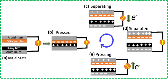 | ||
| Fig. 3 Working mechanism of the X-TENG at (a) initial state, (b) pressed state, (c) separating state, (d) completely separated state, and (e) pressing state. | ||
In the contact separation mode of operation, when the triboelectric layers of the X-TENG device come into contact under the applied force, they exchange charges based on their ability to lose or gain electrons, as shown in Fig. 3(b). The silicone sheet accepts electrons and becomes negatively charged, while the X-ray sheet loses electrons and becomes positively charged. An equilibrium is established because both sheets carry an equal number of opposite charges on their surfaces. Upon removal of the external force, a potential difference develops between the top and bottom electrodes, which drives the flow of electrons from the top electrode to the bottom electrode until a balanced state is reached, as shown in Fig. 3(c) and (d). When the external force is reapplied, the induced charges travel in the opposite direction (Fig. 3(e)), producing an AC electrical output.
In addition, the finite element simulation of the X-TENG operation was performed using COMSOL 6.0 Multiphysics software, and the simulation parameters and results are presented in Table S1, Fig. S4 in Section S4 of the ESI.†
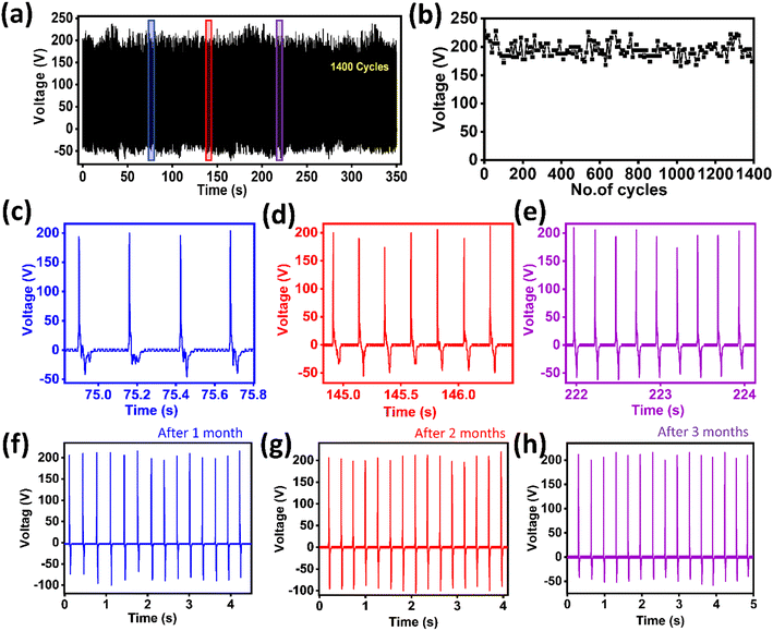
The stability of the fabricated X-TENG device was tested over 10![[thin space (1/6-em)]](https://www.rsc.org/images/entities/char_2009.gif) 000 cycles using a modified linear motor at a frequency of approximately 6 Hz for a period of 30 minutes. The device was found to be stable, and the photographs of the modified linear motor and the TENG response are presented in Fig. S5 in Section S5 of the ESI, along with Video V1.† To test the stability of the TENG under hand tapping force, sets of approximately 30–40 cycles of responses were recorded with a gap of a few seconds, and all such data sets were merged to make a total of approximately 1400 cycles. The TENG responses of 1440 cycles are presented in Fig. 4(a). The output voltage variation as a function of cycle number (every 10th cycle) is presented in Fig. 4(b), which indicates minor changes in the output voltage. These changes are attributed to variations in the hand slapping force.
000 cycles using a modified linear motor at a frequency of approximately 6 Hz for a period of 30 minutes. The device was found to be stable, and the photographs of the modified linear motor and the TENG response are presented in Fig. S5 in Section S5 of the ESI, along with Video V1.† To test the stability of the TENG under hand tapping force, sets of approximately 30–40 cycles of responses were recorded with a gap of a few seconds, and all such data sets were merged to make a total of approximately 1400 cycles. The TENG responses of 1440 cycles are presented in Fig. 4(a). The output voltage variation as a function of cycle number (every 10th cycle) is presented in Fig. 4(b), which indicates minor changes in the output voltage. These changes are attributed to variations in the hand slapping force.
Fig. 4(c)–(e) show magnified views of a few parts of the stability graph, indicating that the X-TENG response is uniform. Moreover, the stability of the X-TENG was tested over a period of three months, as shown in Fig. 4(f)–(h), and was found to be stable. Based on these results, we can conclude that the stability and durability of the X-TENG device are excellent.
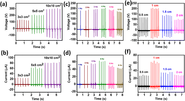
In order to evaluate the performance of the X-TENG device, the effect of different experimental parameters, such as the active area of the device, frequency of applied force, and spacing between the triboelectric layers, were studied. The comparative results of the Voc and Isc of the X-TENG device under these varying parameters are presented in Fig. 5.
Fig. 5(a) and (b) show the variation of the X-TENG output voltage and current with different active areas of the device, ranging from 3 × 3 cm2 to 10 × 10 cm2. It is observed that as the active area of the device increases, the effective contact electrification also increases proportionally, resulting in an increase in the electrical output. The X-TENG output voltage increased from ∼126 V to 291 V, and the current increased from ∼22.7 μA to 81.1 μA with increasing active area. This behaviour is well-supported by previous studies on TENGs.65,66
Fig. 5(c) and (d) present the variation of TENG output voltage and current with different frequencies of applied force. It was observed that the output voltage and current increased initially with the frequency up to 4 Hz and then decreased for higher frequencies.67 The output voltage increased from 178 V (1 Hz) to 198 V (4 Hz) and then decreased to 166 V (6 Hz), while the output current increased from 47.2 μA (1 Hz) to 61 μA (4 Hz) and then decreased to 42.3 μA (6 Hz). The increased electrical output of the X-TENG at high frequencies is attributed to charge accumulation due to a short contact-separation cycle at high frequencies (4 Hz).16,68 Furthermore, the decrease in the electrical output of the X-TENG at high frequencies (≥5 Hz) is due to the inability of the nanogenerator to go back to its original state before the next impact.69
The variation of X-TENG output voltage and current with the spacing between the triboelectric layers is shown in Fig. 5(e) and (f). It was found that the output voltage increased from 116 V (0.5 cm) to 200 V (1 cm) and then decreased to 95.6 V (2 cm). Similarly, the output current increased from 27.3 μA (0.5 cm) to 61 μA (1 cm) and then decreased to 27.6 μA (2 cm). According to the expression for the open-circuit voltage of the TENG (Voc = (σd/ε0)), the electrical output of the TENG should increase with the spacing between the triboelectric layers. However, in the present results, it is observed that the X-TENG output decreases with the increase in spacing ((>1 cm)) between the triboelectric layers. According to the existing literature on other TENGs, the decrease in the electrical output at larger spacing is attributed to a reduced contact area between the triboelectric layers under the application of constant applied force.70 This decrease in effective contact area is a result of the larger sponge spacer dimensions, which increase the elasticity of the sponges. Consequently, a higher applied force is needed to overcome the added elastic force and maintain the same active contact area for the production of the same output voltage. Since the applied force in the current study is constant, a lower output voltage can be anticipated at larger spacing between the triboelectric layers.
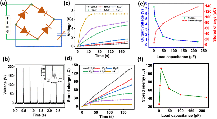
Fig. 6(a) and (b) depict the rectification process and rectified output of the X-TENG. The X-TENG response for one cycle is displayed in the inset of Fig. 6(b), where no peaks are visible on the negative y-axis side owing to the rectification process. The DC output generated by the TENG is utilized to charge capacitors with capacitance values of 1, 4.7, 10, 47, 100, and 220 μF. Fig. 6(c) illustrates the charging curves of these capacitors.
To determine the amount of stored charge on various load capacitors, the product of charging voltage and load capacitance value was calculated, as illustrated in Fig. 6(d). The maximum values of charged voltage and stored charge were plotted as a function of load capacitance in Fig. 6(e), and the trend of the graphs closely matched the literature.71 The stored energy values were computed for each load capacitor to identify the optimum load capacitance value, and the results are presented in Fig. 6(f). The maximum stored energy of 113.8 μJ was observed for a 10 μF load capacitor.
4 Applications of the X-TENG
4.1 Powering light emitting diodes (LEDs)
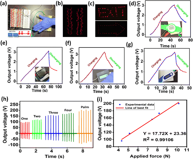
The AC output of the X-TENG was rectified with a full wave bridge rectifier IC and then connected to a series of 240 red LEDs, as depicted in Fig. 7(a). The ON condition of the LEDs, which were powered by the TENG, is shown in Fig. 7(b) (see SI Video V2†). Furthermore, a few of these LEDs were arranged to form an arrow symbol and the text “EXIT” and were powered by the TENG, as demonstrated in Fig. 7(c) (see ESI, Fig. S6 and Videos V3 and V4†). These self-powered indicator displays could prove useful in buildings during power failures resulting from fire accidents or other emergencies in future smart homes.4.2 Self-powered electronic devices
An energy management circuit employing switched-capacitor-converters was utilized to power portable electronic devices, such as a digital watch, calculator, thermometer, and digital hygrometer. The switched-capacitor-converter circuit charged capacitors in a series connection and discharged them in parallel (see ESI, Fig. S2†).48 The DC output generated by the X-TENG was stored by the energy management circuit and utilized to power the electronic devices. The charging and discharging curves of the energy management circuit when powering the devices are presented in Fig. 7(d)–(g). The digital calculator and watch were powered for approximately 10 seconds after charging to around 3 V in 35 seconds (see ESI, Videos V5 and V6†). Similarly, the thermometer and hygrometer were powered for a few seconds using energy stored in a capacitor (see ESI, Videos V7 and V8†). The short powered-on period for the thermometer and hygrometer may be due to the more power consumed by the devices compared to the calculator and watch.4.3 Self-powered force sensor
The X-TENG was also investigated for its potential use as a force sensor. Fig. 7(h) shows the responses of the X-TENG to various applied forces. The applied forces were generated by pressing the X-TENG with different numbers of fingers (e.g., single and double fingers), as depicted in Fig. 7(h). Table 2 summarizes the output voltage and applied force on the X-TENG. The force applied to the X-TENG device was determined using the procedure described in the literature, and a detailed force calculation procedure is presented in the ESI, Section S7.†72,73 The increase in output voltage with the applied force confirms that the X-TENG has the potential to be used as a force sensor. The increase in output voltage is attributed to the increase in frictional contact points between the triboelectric layers with the applied force.74,75 As illustrated in Fig. 7(i), the generated output voltage and the applied force have a linear fitting, and the fitting equation for the output voltage (Y) and the applied force (X) can be represented as Y = 17.72X + 23.36, with an R-squared value of 0.99106.| S. no | The way force is applied on the X-TENG | Output voltage (V) | Calculated force approximately (N) |
|---|---|---|---|
| 1 | Single finger | 96 | 4.33 |
| 2 | Two fingers | 117 | 5.13 |
| 3 | Three fingers | 156 | 7.45 |
| 4 | Four fingers | 173 | 8.16 |
| 5 | Full palm | 200 | 10.18 |
4.4 TENG applications in smart buildings
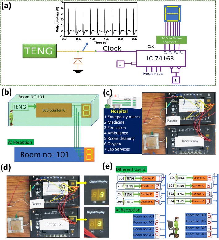
We have developed a proof of concept for smart buildings (such as those providing medical or hotel services) enabled by the X-TENG. Fig. 8(a) shows the schematic of all the connection details. We used the IC 74163 to make a decade counter (0–9), and connected the outputs (Qd − Qa) to a seven-segment display. We modified the X-TENG output with the help of a Zener diode to use it as a clock pulse for the IC 74163 counter. The counter output increases its counting with every tap on the X-TENG device (see ESI, Videos V9 and V10). The schematic and original proof of concept are shown in Fig. 8(b) and (c).In this model, the counter output is connected to two seven-segment displays: one in the user's room (hotel/hospital) and the other at the reception of the hotel/hospital, as shown in Fig. 8(b). When the user presses the X-TENG, the counter output increases by one number in both the room and the reception simultaneously. Each number on the counter is assigned to a particular service associated with the hotel/hospital, as shown in Fig. 8(c). For example, number 3 is assigned to a fire accident happening in the room. Whenever a fire accident occurs in a room, the user can press the X-TENG three times so that it displays 3 in the reception, as shown in Fig. 8(d). Based on the number displayed on the counter, appropriate action can be taken by the administrative authority. In another example, in a hotel, the user can press the X-TENG a desired number of times to request a particular service. This assignment list can be changed based on the user's requirements (see ESI, Fig. S7†).
Fig. 8(e) depicts a typical model of a three-story building with four rooms per floor. The proposed X-TENG devices are installed in each room, and the outputs of the counters are connected to seven-segment displays at the reception with the corresponding room numbers. Each user in the eight different rooms can request the desired service simultaneously by pressing the X-TENG the required number of times. This X-TENG-enabled service can be extended to large multi-story buildings. An X-TENG-enabled BCD counter is useful for counting vehicles in and out of parking lots in a commercial building and counting the number of people entering and leaving a shopping mall. Additionally, an X-TENG-enabled BCD counter can be useful in banks, hospitals, and hotels to generate and display token numbers. Overall, the X-TENG has the potential to revolutionize smart building technology.
5 Conclusions
In conclusion, a cost-effective and scalable approach for fabricating a robust TENG using waste X-ray films and silicone sheets for mechanical energy harvesting has been presented. This is the first study to utilize medical waste (X-ray films) in TENG technology. The X-TENG device achieved a Voc of 201 V, Isc of 62.8 A and an output power density of 1.39 W m−2. The TENG also exhibited high stability and durability, undergoing over 10![[thin space (1/6-em)]](https://www.rsc.org/images/entities/char_2009.gif) 000 cycles of testing and more than three months of continuous operation without any significant degradation. The X-TENG was successfully used to power 240 commercial red LEDs, functioning as self-powered indicator displays, and demonstrated as a self-powered force sensor. Furthermore, it was capable of powering electronic devices such as a calculator, digital watch, hygrometer, and thermometer using charged capacitors. Lastly, the TENG was employed in a proof-of-concept for smart building applications.
000 cycles of testing and more than three months of continuous operation without any significant degradation. The X-TENG was successfully used to power 240 commercial red LEDs, functioning as self-powered indicator displays, and demonstrated as a self-powered force sensor. Furthermore, it was capable of powering electronic devices such as a calculator, digital watch, hygrometer, and thermometer using charged capacitors. Lastly, the TENG was employed in a proof-of-concept for smart building applications.
Author contributions
Conceptualization: RRK and KUK, experiments: MN, SP, AB, and KB, methodology: RRK, KUK, and KP, software: RRK, MN, SP, and KP, formal analysis: MN, SP, RRK, and KUK, visualization: MN, SP, AB, and RRK, supervision: RRK and KUK, writing—original draft: RRK and MN, and writing-review & editing: RRK, MN, SP, and KUK.Conflicts of interest
There are no conflicts to declare.Acknowledgements
The authors would like to thank the Department of Physics and Centre for Research and Instrument facility (CRIF), NIT-Warangal, for providing their research facilities. The authors would like to acknowledge the I-STEM (Indian Science Technology and Engineering facilities) for providing COMSOL6.0 software for the FEM analysis.References
- M. G. Kibria, N. I. Masuk, R. Safayet, H. Q. Nguyen and M. Mourshed, Plastic Waste: Challenges and Opportunities to Mitigate Pollution and Effective Management, Int. J. Environ. Res., 2023, 17 DOI:10.1007/s41742-023-00507-z.
- I. Tsuchimoto and Y. Kajikawa, Recycling of Plastic Waste: A Systematic Review Using Bibliometric Analysis, Sustainability, 2022, 14, 16340, DOI:10.3390/su142416340.
- H. Sardon and A. P. Dove, Plastics recycling with a difference: a novel plastic with useful properties can easily be recycled again and again, Science, 2018, 380–381, DOI:10.1126/science.aat4997.
- J. Y. Q. Teo, A. Ong, T. T. Y. Tan, X. Li, X. J. Loh and J. Y. C. Lim, Materials from waste plastics for CO2 capture and utilisation, Green Chem., 2022, 24, 6086–6099, 10.1039/d2gc02306g.
- S. Maithomklang, K. Wathakit, E. Sukjit, B. Sawatmongkhon and J. Srisertpol, Utilizing Waste Plastic Bottle-Based Pyrolysis Oil as an Alternative Fuel, ACS Omega, 2022, 7, 20542–20555, DOI:10.1021/acsomega.1c07345.
- X. Feng, Q. Li and K. Wang, Waste Plastic Triboelectric Nanogenerators Using Recycled Plastic Bags for Power Generation, ACS Appl. Mater. Interfaces, 2021, 13, 400–410, DOI:10.1021/acsami.0c16489.
- E. Naderi Kalali, S. Lotfian, M. Entezar Shabestari, S. Khayatzadeh, C. Zhao and H. Yazdani Nezhad, A critical review of the current progress of plastic waste recycling technology in structural materials, Curr. Opin. Green Sustain. Chem., 2023, 40, 100763, DOI:10.1016/j.cogsc.2023.100763.
- U. E. Edike, O. J. Ameh and M. O. Dada, Performance of polymer bricks produced with plastic waste, Innov. Infrastruct. Solut., 2022, 8, 51, DOI:10.1007/s41062-022-01021-5.
- H. Chen, R. Qin, C. L. Chow and D. Lau, Recycling thermoset plastic waste for manufacturing green cement mortar, Cem. Concr. Compos., 2023, 137, 104922, DOI:10.1016/j.cemconcomp.2022.104922.
- M. H. Esmaeili, H. Norouzi and F. Niazi, Evaluation of mechanical and performance characteristics of a new composite railway sleeper made from recycled plastics, mineral fillers and industrial wastes, Compos. B Eng., 2023, 254, 110581, DOI:10.1016/j.compositesb.2023.110581.
- K. Zheng, Y. Wu, Z. Hu, S. Wang, X. Jiao, J. Zhu, Y. Sun and Y. Xie, Progress and perspective for conversion of plastic wastes into valuable chemicals, Chem. Soc. Rev., 2022, 52, 8–29, 10.1039/d2cs00688j.
- L. Yaqoob, T. Noor and N. Iqbal, Conversion of Plastic Waste to Carbon-Based Compounds and Application in Energy Storage Devices, ACS Omega, 2022, 7, 13403–13435, DOI:10.1021/acsomega.1c07291.
- D. Yao, H. Li, B. C. Mohan, A. K. Prabhakar, Y. Dai and C. H. Wang, Conversion of Waste Plastic Packings to Carbon Nanomaterials: Investigation into Catalyst Material, Waste Type, and Product Applications, ACS Sustain. Chem. Eng., 2022, 10, 1125–1136, DOI:10.1021/acssuschemeng.1c05945.
- W. A. Algozeeb, P. E. Savas, D. X. Luong, W. Chen, C. Kittrell, M. Bhat, R. Shahsavari and J. M. Tour, Flash graphene from plastic waste, ACS Nano, 2020, 14, 15595–15604, DOI:10.1021/acsnano.0c06328.
- A. Kumar, H. S. Pali and M. Kumar, A comprehensive review on the production of alternative fuel through medical plastic waste, Sustain. Energy Technol. Assessments, 2023, 55, 102924, DOI:10.1016/j.seta.2022.102924.
- F. R. Fan, Z. Q. Tian and Z. Lin Wang, Flexible triboelectric generator, Nano Energy, 2012, 1, 328–334, DOI:10.1016/j.nanoen.2012.01.004.
- W. Zhang, Y. Shi, Y. Li, X. Chen and H. Shen, A Review: Contact Electrification on Special Interfaces, Front. Mater., 2022, 9, 909746, DOI:10.3389/fmats.2022.909746.
- C. Wu, A. C. Wang, W. Ding, H. Guo and Z. L. Wang, Triboelectric Nanogenerator: A Foundation of the Energy for the New Era, Adv. Energy Mater., 2019, 9, 1–25, DOI:10.1002/aenm.201802906.
- P. Basset, S. P. Beeby, C. Bowen, Z. J. Chew, A. Delbani, R. D. I. G. Dharmasena, B. Dudem, F. R. Fan, D. Galayko, H. Guo, J. Hao, Y. Hou, C. Hu, Q. Jing, Y. H. Jung, S. K. Karan, S. Kar-Narayan, M. Kim, S.-W. Kim, Y. Kuang, K. J. Lee, J. Li, Z. Li, Y. Long, S. Priya, X. Pu, T. Ruan, S. R. P. Silva, H. S. Wang, K. Wang, X. Wang, Z. L. Wang, W. Wu, W. Xu, H. Zhang, Y. Zhang and M. Zhu, Roadmap on nanogenerators and piezotronics, APL Mater., 2022, 10, 109201, DOI:10.1063/5.0085850.
- S. Pan and Z. Zhang, Fundamental theories and basic principles of triboelectric effect: a review, Friction, 2019, 7, 2–17, DOI:10.1007/s40544-018-0217-7.
- R. Zhang and H. Olin, Material choices for triboelectric nanogenerators: a critical review, EcoMat, 2020, 2, 1–13, DOI:10.1002/eom2.12062.
- H. Zou, Y. Zhang, L. Guo, P. Wang, X. He, G. Dai, H. Zheng, C. Chen, A. C. Wang, C. Xu and Z. L. Wang, Quantifying the triboelectric series, Nat. Commun., 2019, 10, 1427, DOI:10.1038/s41467-019-09461-x.
- J. Bae, Q. M. Saqib, R. A. Shaukat, M. U. Khan and M. Chougale, Biowaste peanut shell powder-based triboelectric nanogenerator for biomechanical energy scavenging and sustainably powering electronic supplies, ACS Appl. Electron. Mater., 2020, 2, 3953–3963, DOI:10.1021/acsaelm.0c00791.
- R. A. Shaukat, Q. M. Saqib, M. U. Khan, M. Y. Chougale and J. Bae, Bio-waste sunflower husks powder based recycled triboelectric nanogenerator for energy harvesting, Energy Rep., 2021, 7, 724–731, DOI:10.1016/j.egyr.2021.01.036.
- J. Kaur, R. S. Sawhney, H. Singh and M. Singh, Electricity nanogenerator from egg shell membrane: a natural waste bioproduct, Int. J. Green Energy, 2020, 17, 309–318, DOI:10.1080/15435075.2020.1727482.
- J. M. Wu, C. K. Chang and Y. T. Chang, High-output current density of the triboelectric nanogenerator made from recycling rice husks, Nano Energy, 2016, 19, 39–47, DOI:10.1016/j.nanoen.2015.11.014.
- J. Ma, J. Zhu, P. Ma, Y. Jie, Z. L. Wang and X. Cao, Fish bladder film-based triboelectric nanogenerator for noncontact position monitoring, ACS Energy Lett., 2020, 5, 3005–3011, DOI:10.1021/acsenergylett.0c01062.
- G. Han, B. Wu and Y. Pu, A triboelectric nanogenerator based on waste plastic bags for flexible vertical interconnection system, Microsyst. Technol., 2020, 26, 3893–3899, DOI:10.1007/s00542-020-04879-6.
- P. R. Sankar, K. Prakash, P. Supraja, R. Rakesh Kumar, S. Mishra and D. Haranath, A triboelectric nanogenerator based on food packaging Aluminium foil and Parafilm for self-powered electronics, Phys. Scr., 2021, 96, 125005, DOI:10.1088/1402-4896/ac2086.
- X. Ren, H. Fan, J. Ma, C. Wang, Y. Zhao and S. Lei, Triboelectric nanogenerators based on fluorinated wasted rubber powder for self-powering application, ACS Sustain. Chem. Eng., 2017, 5, 1957–1964, DOI:10.1021/acssuschemeng.6b02756.
- Z. Zhou, X. Li, Y. Wu, H. Zhang, Z. Lin, K. Meng, Z. Lin, Q. He, C. C. Sun, J. Yang and Z. L. Wang, Wireless self-powered sensor networks driven by triboelectric nanogenerator for in-situ real time survey of environmental monitoring, Nano Energy, 2018, 53, 501–507, DOI:10.1016/j.nanoen.2018.08.055.
- P. Zhang, W. Zhang and H. Zhang, A triboelectric nanogenerator based on waste polyvinyl chloride for Morse code generator, Sens. Actuators, A, 2021, 322, 112633, DOI:10.1016/j.sna.2021.112633.
- K. Xia, Z. Zhu, J. Fu, Y. Li, Y. Chi, H. Zhang, C. Du and Z. Xu, A triboelectric nanogenerator based on waste tea leaves and packaging bags for powering electronic office supplies and behavior monitoring, Nano Energy, 2019, 60, 61–71, DOI:10.1016/j.nanoen.2019.03.050.
- N. R. Alluri, N. P. Maria Joseph Raj, G. Khandelwal, V. Vivekananthan and S.-J. Kim, Aloe vera: a tropical desert plant to harness the mechanical energy by triboelectric and piezoelectric approaches, Nano Energy, 2020, 73, 104767, DOI:10.1016/j.nanoen.2020.104767.
- S. Jakmuangpak, T. Prada, W. Mongkolthanaruk, V. Harnchana and S. Pinitsoontorn, Engineering Bacterial Cellulose Films by Nanocomposite Approach and Surface Modification for Biocompatible Triboelectric Nanogenerator, ACS Appl. Electron. Mater., 2020, 2, 2498–2506, DOI:10.1021/acsaelm.0c00421.
- Y. Chi, K. Xia, Z. Zhu, J. Fu, H. Zhang, C. Du and Z. Xu, Rice paper-based biodegradable triboelectric nanogenerator, Microelectron. Eng., 2019, 216, 111059, DOI:10.1016/j.mee.2019.111059.
- Y. Yetri, A. T. Hoang, D. D. Mursida, E. T. Muldarisnur and M. Q. Chau, Synthesis of Activated Carbon Monolith Derived from Cocoa Pods for Supercapacitor Electrodes Application, Energy Sources, Part A Recovery, Util. Environ. Eff., 2020, 1–15, DOI:10.1080/15567036.2020.1811433.
- X. Ren, H. Fan, J. Ma, C. Wang, Y. Zhao and S. Lei, Triboelectric nanogenerators based on fluorinated wasted rubber powder for self-powering application, ACS Sustain. Chem. Eng., 2017, 5, 1957–1964, DOI:10.1021/acssuschemeng.6b02756.
- B. Dudem, R. D. I. G. Dharmasena, R. Riaz, V. Vivekananthan, K. G. U. Wijayantha, P. Lugli, L. Petti and S. R. P. Silva, Wearable Triboelectric Nanogenerator from Waste Materials for Autonomous Information Transmission via Morse Code, ACS Appl. Mater. Interfaces, 2022, 14, 5328–5337, DOI:10.1021/acsami.1c20984.
- S. M. Nawaz, M. Saha, N. Sepay and A. Mallik, Energy-from-waste: a triboelectric nanogenerator fabricated from waste polystyrene for energy harvesting and self-powered sensor, Nano Energy, 2022, 104, 107902, DOI:10.1016/j.nanoen.2022.107902.
- M. U. Bukhari, A. Khan, K. Q. Maqbool, A. Arshad, K. Riaz and A. Bermak, Waste to energy: facile, low-cost and environment-friendly triboelectric nanogenerators using recycled plastic and electronic wastes for self-powered portable electronics, Energy Rep., 2022, 8, 1687–1695, DOI:10.1016/j.egyr.2021.12.072.
- K. S. Moreira, Y. A. Santos da Campo, E. Lorenzett and T. A. L. Burgo, Low-cost triboelectric nanogenerator based on aseptic carton package, Results Eng., 2023, 17, 100965, DOI:10.1016/j.rineng.2023.100965.
- B. Dudem, R. D. I. G. Dharmasena, R. Riaz, V. Vivekananthan, K. G. U. Wijayantha, P. Lugli, L. Petti and S. R. P. Silva, Wearable Triboelectric Nanogenerator from Waste Materials for Autonomous Information Transmission via Morse Code, ACS Appl. Mater. Interfaces, 2022, 14, 5328–5337, DOI:10.1021/acsami.1c20984.
- H. Varghese and A. Chandran, Triboelectric Nanogenerator from Used Surgical Face Mask and Waste Mylar Materials Aiding the Circular Economy, ACS Appl. Mater. Interfaces, 2021, 13, 51132–51140, DOI:10.1021/acsami.1c16557.
- Ref. 6 Waste Plastic Triboelectric Nanogenerators Using Recycled Plastic Bags for Power Generation Enhanced Reader.pdf.
- G. Khandelwal, A. Chandrasekhar, N. Rao, V. Vivekananthan, N. Prashanth, M. Joseph and S. Kim, Trash to energy: a facile, robust and cheap approach for mitigating environment pollutant using household triboelectric nanogenerator, Appl. Energy, 2018, 219, 338–349, DOI:10.1016/j.apenergy.2018.03.031.
- T. Wang, S. Li, X. Tao, Q. Yan, X. Wang, Y. Chen, F. Huang, H. Li, X. Chen and Z. Bian, Fully biodegradable water-soluble triboelectric nanogenerator for human physiological monitoring, Nano Energy, 2022, 93, 106787, DOI:10.1016/j.nanoen.2021.106787.
- W. Liu, Z. Wang, G. Wang, Q. Zeng, W. He, L. Liu, X. Wang, Y. Xi, H. Guo, C. Hu and Z. L. Wang, Switched-capacitor-convertors based on fractal design for output power management of triboelectric nanogenerator, Nat. Commun., 2020, 11, 1883, DOI:10.1038/s41467-020-15373-y.
- Y. A. Stetsiv, M. M. Yatsyshyn, D. Nykypanchuk, S. A. Korniy, I. Saldan, O. v. Reshetnyak and T. J. Bednarchuk, Characterization of polyaniline thin films prepared on polyethylene terephthalate substrate, Polym. Bull., 2021, 78, 6251–6265, DOI:10.1007/s00289-020-03426-7.
- C. Guillén and J. Herrero, Comparison study of ITO thin films deposited by sputtering at room temperature onto polymer and glass substrates, Thin Solid Films, 2005, 480–481, 129–132, DOI:10.1016/j.tsf.2004.11.040.
- Y. Liu, D. Zhu, J. Sun, Y. Wu and C. Gao, A new cross-linked system of silicone rubber based on silicone-polyurea block copolymer, Polym. Adv. Technol., 2018, 29, 2064–2071, DOI:10.1002/pat.4314.
- O. M. Hemeda, A. M. A. Henaish, B. I. Salem, F. S. El-Sbakhy and M. A. Hamad, The dielectric and magnetic properties of RTV-silicon rubber Ni–Cr ferrite composites, Appl. Phys. A: Mater. Sci. Process., 2020, 126, 121, DOI:10.1007/s00339-020-3297-y.
- J. Wang, C. Ji, Y. Yan, D. Zhao and L. Shi, Mechanical and ceramifiable properties of silicone rubber filled with different inorganic fillers, Polym. Degrad. Stab., 2015, 121, 149–156, DOI:10.1016/j.polymdegradstab.2015.09.003.
- R. Yang, Y. Qin, C. Li, L. Dai and Z. L. Wang, Characteristics of output voltage and current of integrated nanogenerators, Appl. Phys. Lett., 2009, 94, 92–95, DOI:10.1063/1.3072362.
- S. Paria, R. Bera, S. K. Karan, A. Maitra, A. K. Das, S. K. Si, L. Halder, A. Bera and B. B. Khatua, Insight into Cigarette Wrapper and Electroactive Polymer Based Efficient TENG as Biomechanical Energy Harvester for Smart Electronic Applications, ACS Appl. Energy Mater., 2018, 1, 4963–4975, DOI:10.1021/acsaem.8b00951.
- J. Chen, G. Zhu, W. Yang, Q. Jing, P. Bai, Y. Yang, T. C. Hou and Z. L. Wang, Harmonic-resonator-based triboelectric nanogenerator as a sustainable power source and a self-powered active vibration sensor, Adv. Mater., 2013, 25, 6094–6099, DOI:10.1002/adma.201302397.
- B. Yang, W. Zeng, Z. H. Peng, S. R. Liu, K. Chen and X. M. Tao, A Fully Verified Theoretical Analysis of Contact-Mode Triboelectric Nanogenerators as a Wearable Power Source, Adv. Energy Mater., 2016, 6, 1–8, DOI:10.1002/aenm.201600505.
- T. Kamilya, P. K. Sarkar and S. Acharya, Unveiling Peritoneum Membrane for a Robust Triboelectric Nanogenerator, ACS Omega, 2019, 4, 17684–17690, DOI:10.1021/acsomega.9b01963.
- C. Sukumaran, V. Vivekananthan, V. Mohan, Z. C. Alex, A. Chandrasekhar and S.-J. Kim, Triboelectric nanogenerators from reused plastic: an approach for vehicle security alarming and tire motion monitoring in rover, Appl. Mater. Today, 2020, 19, 100625, DOI:10.1016/j.apmt.2020.100625.
- G. Zhu, Z. H. Lin, Q. Jing, P. Bai, C. Pan, Y. Yang, Y. Zhou and Z. L. Wang, Toward large-scale energy harvesting by a nanoparticle-enhanced triboelectric nanogenerator, Nano Lett., 2013, 13, 847–853, DOI:10.1021/nl4001053.
- C. K. Jeong, K. M. Baek, S. Niu, T. W. Nam, Y. H. Hur, D. Y. Park, G. T. Hwang, M. Byun, Z. L. Wang, Y. S. Jung and K. J. Lee, Topographically-designed triboelectric nanogenerator via block copolymer self-assembly, Nano Lett., 2014, 14, 7031–7038, DOI:10.1021/nl503402c.
- A. You, X. Zhang, X. Peng, K. Dong, Y. Lu and Q. Zhang, A Skin-Inspired Triboelectric Nanogenerator with an Interpenetrating Structure for Motion Sensing and Energy Harvesting, Macromol. Mater. Eng., 2021, 306, 2100147, DOI:10.1002/mame.202100147.
- F. R. Fan, Z. Q. Tian and Z. Lin Wang, Flexible triboelectric generator, Nano Energy, 2012, 1, 328–334, DOI:10.1016/j.nanoen.2012.01.004.
- C. Wu, A. C. Wang, W. Ding, H. Guo and Z. L. Wang, Triboelectric Nanogenerator: A Foundation of the Energy for the New Era, Adv. Energy Mater., 2019, 9, 1–25, DOI:10.1002/aenm.201802906.
- T. Kamilya, P. K. Sarkar and S. Acharya, Unveiling Peritoneum Membrane for a Robust Triboelectric Nanogenerator, ACS Omega, 2019, 4, 17684–17690, DOI:10.1021/acsomega.9b01963.
- Y. Lu, H. Tian, J. Cheng, F. Zhu, B. Liu, S. Wei, L. Ji and Z. L. Wang, Decoding lip language using triboelectric sensors with deep learning, Nat. Commun., 2022, 13, 1–12, DOI:10.1038/s41467-022-29083-0.
- R. Pan, W. Xuan, J. Chen, S. Dong, H. Jin, X. Wang, H. Li and J. Luo, Fully biodegradable triboelectric nanogenerators based on electrospun polylactic acid and nanostructured gelatin films, Nano Energy, 2018, 45, 193–202, DOI:10.1016/j.nanoen.2017.12.048.
- Y. H. Ko, G. Nagaraju, S. H. Lee and J. S. Yu, PDMS-based Triboelectric and Transparent Nanogenerators with ZnO Nanorod Arrays, ACS Appl. Mater. Interfaces, 2014, 6, 6631–6637, DOI:10.1021/am5018072.
- X. S. Zhang, M. di Han, R. X. Wang, F. Y. Zhu, Z. H. Li, W. Wang and H. X. Zhang, Frequency-multiplication high-output triboelectric nanogenerator for sustainably powering biomedical microsystems, Nano Lett., 2013, 13, 1168–1172, DOI:10.1021/nl3045684.
- T. C. Hou, Y. Yang, H. Zhang, J. Chen, L. J. Chen and Z. Lin Wang, Triboelectric nanogenerator built inside shoe insole for harvesting walking energy, Nano Energy, 2013, 2, 856–862, DOI:10.1016/j.nanoen.2013.03.001.
- Y. Yao, T. Jiang, L. Zhang, X. Chen, Z. Gao and Z. L. Wang, Charging System Optimization of Triboelectric Nanogenerator for Water Wave Energy Harvesting and Storage, ACS Appl. Mater. Interfaces, 2016, 8(33), 21398–21406 CrossRef CAS PubMed.
- A. Sultana, M. M. Alam, S. Garain, T. K. Sinha, T. R. Middya and D. Mandal, An Effective Electrical Throughput from PANI Supplement ZnS Nanorods and PDMS-Based Flexible Piezoelectric Nanogenerator for Power up Portable Electronic Devices: An Alternative of MWCNT Filler, ACS Appl. Mater. Interfaces, 2015, 7, 19091–19097, DOI:10.1021/acsami.5b04669.
- F. R. Fan, L. Lin, G. Zhu, W. Wu, R. Zhang and Z. L. Wang, Transparent triboelectric nanogenerators and self-powered pressure sensors based on micropatterned plastic films, Nano Lett., 2012, 12, 3109–3114, DOI:10.1021/nl300988z.
- H. Guo, T. Li, X. Cao, J. Xiong, Y. Jie, M. Willander, X. Cao, N. Wang and Z. L. Wang, Self-Sterilized Flexible Single-Electrode Triboelectric Nanogenerator for Energy Harvesting and Dynamic Force Sensing, ACS Nano, 2017, 11, 856–864, DOI:10.1021/acsnano.6b07389.
- X. Shen, W. Han, Y. Jiang, Q. Ding, X. Li, X. Zhao and Z. Li, Punching pores on cellulose fiber paper as the spacer of triboelectric nanogenerator for monitoring human motion, Energy Rep., 2020, 6, 2851–2860, DOI:10.1016/j.egyr.2020.10.011.
Footnote |
| † Electronic supplementary information (ESI) available. See DOI: https://doi.org/10.1039/d3va00018d |
| This journal is © The Royal Society of Chemistry 2023 |

