
 Open Access Article
 This Open Access Article is licensed under a
 Creative Commons Attribution 3.0 Unported Licence
Electrokinetic generation of iron-rich barriers in soils: realising the potential for nuclear site management and decommissioning†
Jamie M.
Purkis
a,
Frances
Burrell
 a,
James R.
Brydie
b,
James
Graham
c,
Laurence
Hopkinson
d and
Andrew B.
Cundy
*a
a,
James R.
Brydie
b,
James
Graham
c,
Laurence
Hopkinson
d and
Andrew B.
Cundy
*a
aGAU-Radioanalytical, School of Ocean and Earth Science, University of Southampton, National Oceanography Centre (Southampton), European Way, Southampton, SO14 3ZH, UK. E-mail: A.Cundy@soton.ac.uk
bCanmetENERGY, Natural Resources Canada, Devon, Alberta T9G 1A8, Canada
cNational Nuclear Laboratory, Central Laboratory, Sellafield, Seascale, Cumbria CA20 1PG, UK
dSchool of Applied Sciences, University of Brighton, Lewes Road, Brighton, BN2 4GJ, UK
First published on 6th March 2023
Abstract
Following earlier field-scale pilot work on nuclear site materials in the late 2000s, there has recently been renewed research and industry interest in the application of electrokinetic technologies for nuclear site management and remediation in the UK. One relatively novel application of electrokinetics is the use of sacrificial steel electrodes (coupled with an in situ generated pH–Eh gradient in the treated material) to precipitate sub-surface iron-rich barriers for groundwater and/or leachate containment, which could be used to grout or contain contaminated fluids in the sub-surface on working nuclear sites or sites undergoing decommissioning. Here, we report previously unpublished data from two work programmes exploring the higher Technology Readiness Level (TRL) application of this electrokinetic iron-barrier approach to materials typical of those found in the subsurface of the Sellafield nuclear licensed site, UK. The first programme, funded by the UK National Nuclear Laboratory (NNL), assessed the electrokinetic generation of iron-rich barriers at metre + scale in simulated Sellafield materials, while the second programme, funded under the current UK TRANSCEND consortium project, examined electrokinetic iron-barrier formation at smaller (<1 m) scale, but in real site materials. Both programmes indicate that iron-rich barriers can be conveniently and electrokinetically grown in different geometries over reasonable timescales (months) in realistic site subsurface materials (sands), in electrolytes similar to natural waters found in the environment. Voltage requirements are low (<1 V cm−1) with energy and consumables costs of no more than single-digit or tens of US dollars at the metre-plus scale. Further work is needed however to assess the longevity of the iron precipitates forming the subsurface barrier, and to explore barrier generation at the geometries and scales required for (site specific) field application.
Environmental significanceWorking nuclear sites (and those undergoing decommissioning) provide a range of serious environmental challenges, including management of contaminated groundwaters and liquid waste spillages. Following earlier work on nuclear site materials in the 2000s, there has recently been renewed research and industry interest in the application of electrokinetic technologies for nuclear site management and decommissioning, particularly for wastes and groundwater management via stabilization and grouting, or subsurface barrier generation. Here, we assess and generate in situ electrokinetically-grown iron barriers at scale, using simulated and real material from an internationally-important nuclear site, for the first time. By providing new insights into scalability we make these in situ barrier technologies, which mimic natural iron mineralization processes, potentially attractive options for risk mitigation at nuclear sites. |
1. Introduction
Electrokinetic remediation (EKR) is a potentially valuable addition to the engineer's toolbox of technologies for the treatment of contaminated soils and wastes, where organic and/or inorganic contaminant species are force-migrated through a natural or anthropogenically-modified material using an applied electric field. The technique works in a variety of low-permeability substrates including inhomogeneous, low-permeability (e.g. clayey) soils, can be applied ex or in situ,1 and has been used by a range of groups for the treatment of metal,2 organic3 and radioactively4 contaminated materials. Alongside other in situ technologies (e.g. phyto- and bio-remediation, permeable reactive barriers, etc.), EKR offers significant advantages over ex situ technologies (e.g. excavation, pump-and-treat), as (for in situ technologies) the need to physically handle and transport materials is minimized. At sites with radioactive contamination, for example, this is vital where worker safety is a top priority.4 Further, where the physical removal of contaminated material is not possible (e.g. for contaminated buried (geological) materials or soil under a structure), EKR may still be applied. Although the remediation timeframe may be longer than for ex situ methods, the cost is anticipated to be lower, which is important for large, site-scale, treatment.In addition to conventional EKR, one promising avenue for EKR technology is the combined forced migration of contaminants plus in situ precipitation of mineral barriers. With increasing barrier precipitation, permeability decreases, which allows for manipulation of local-scale hydraulic conditions, and possible containment of contaminated groundwater or leachates. Ferric iron remediation and stabilisation (FIRS) is a technology developed and patented5 in 2007 that deliberately corrodes stainless or mild steel electrodes (using direct current) to do this. Iron (as Fe2+) leached from a sacrificial anode(s) migrates between electrodes in the pore space of contaminated substrates and is oxidized and precipitates as it encounters the pH gradient developed during the EKR process (Fig. 1). The soil mineralogy, grain size boundaries and fluid flow all influence the growth of these mineral phases, whereby clay promotes amorphous iron-rich ‘pans’,6 and sands and silts encourage the coating of soil particles with sorptive,7 iron-rich coatings.8 These iron phases may be generated remotely in the subsurface in a number of configurations or geometries, depending on electrode design and placement, forming a physical barrier to groundwater flow or stabilizing and strengthening soils.9 Authigenic iron-rich phases are common in surface and sub-surface materials, for example, forming Fe-rich “pans” in soils, or Liesegang-like bands, which are alternating iron-rich, iron-poor rings extending radially and concentrically from a central core; these are important as they can influence hydro(geo)logy at or around a given site.10 Iron bands or barriers in soils, particularly when grown deliberately, are therefore important as they influence flow paths and therefore contaminant transport.
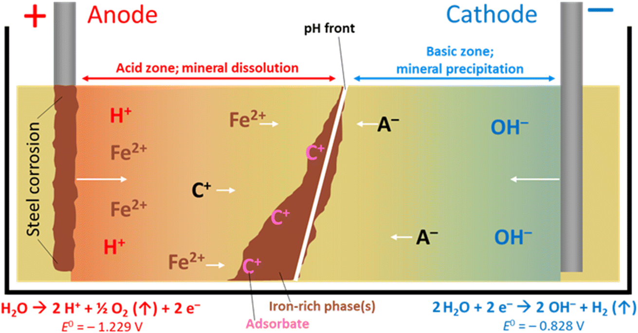 | ||
| Fig. 1 The FIRS process, with precipitation of iron-rich phases. Cation (C+) and anion (A−) movement with pH gradient, towards electrodes of opposing charge, is shown. Water electrolysis half-cell values are vs. SHE. The oxidation of ferrous to ferric iron (Fe2+ to Fe3+E° = −0.771 V vs. SHE)24 typically occurs by diffusion of dioxygen through interstitial pore waters. System uses direct current application. | ||
A schematic for the growth of electrokinetically generated iron-rich phases in soils is given in Fig. 1. Iron, from anode corrosion, migrates towards the cathode before precipitating at the pH–Eh “front” generated by the electric potential (which can range from ca. pH 2 in the acidic zone to >pH 10 in the alkaline zone) in the treated soil, sediment or waste material. The form of iron precipitated depends on the solution pH, soil type, dissolved oxygen, etc., and the precipitated species/minerals can include goethite (α-FeO(OH)), lepidocrocite (γ-FeO(OH)), elemental iron (Fe0), maghemite (γ-Fe2O3), magnetite (Fe3O4, (Fe2+Fe3+2)O4), and limonite (FeO(OH)·nH2O; n is an integer). Other crystalline and amorphous iron oxyhydroxides (rusts, green rusts,11etc.) are also possible.6,9 These phases are effective adsorbents of a range of contaminants and their surfaces are redox active12 (potentials ranging from −0.5 to +1.1 V vs. the standard hydrogen electrode, SHE),13 making iron-rich barriers grown in situ a potentially attractive technology for (a), containment and management of contaminated groundwater or leachates, and (b), in situ sorption or reductive precipitation of contaminants onto these iron-rich phases.14–23 Following cessation of applied current the pH gradient dissipates, leaving a solid Fe-rich barrier that can be extracted, or left in place in the subsurface.
In 2005 Faulkner et al. demonstrated that impermeable (<10−9 m s−1) iron-rich barriers could be grown at laboratory scale in both vertical and horizontal arrangements.9 Additional work by Cundy and Hopkinson (2005)6 expanded this to the treatment of 60Co-contaminated estuarine deposits near the Sellafield facility, Cumbria, UK. Low voltage (<0.2 V cm−1) iron-barrier growth (over 17 days) offered significant enhancements in sediment shear strength (which increased from <0.5 to 20 kN m−2) and mechanical strength (final unconfined compressive strength of 10.8 N mm−2, equivalent to sandstone), with the removal of up to 50% of 60Co in contaminated sediments. EKR and FIRS have also been demonstrated to be effective in the treatment of Cr6+ contaminated wastes, via electrokinetic iron injection.12
Moving from the laboratory to the field and (finally) routine site scale application however remains a key limitation to EKR techniques, with more studies required at larger scale, to determine the scalability, applicability, reliability and cost-effectiveness of EKR for site remediation.25,26 Here, we report the remote precipitation of iron-rich barriers, in (i) controlled geometries in metre-plus cells, and (ii) silica-rich subsurface materials from the UK's Sellafield nuclear facility, Cumbria. We incorporate the results of previously unpublished industrial research, conducted between 2003–2007, which have been released for this paper, and supplement this with recent work (2020–2022) carried out in the ongoing UK TRANSCEND (TRANsformative SCience and Engineering and Nuclear Decommissioning) project, which brings together 11 UK Universities and 8 industry partners to carry out fundamental and applied research to support innovative technology developments in nuclear decommissioning and waste management. We conclude by assessing the potential wider application of EKR barrier technologies in nuclear site management and decommissioning, for example, in the immobilization of site contaminants in the subsurface and/or used as hydraulic containment techniques, at field scale.
2. Materials and methods
2.1 Overview
The work described here was undertaken by a number of organizations, including the predecessor organizations of the National Nuclear Laboratory (NNL), Nexia Solutions, British Nuclear Fuels Ltd (BNFL), C-Tech Innovation Ltd (under contract to Nexia Solutions) between 2003 and 2007 and, separately, the University of Southampton (2020–2022), in two programmes of research assessing the potential for combining EKR with in situ barrier precipitation for nuclear site application, using simulated and real subsurface materials from the UK's Sellafield nuclear site as a case study. We summarize this work below, dividing it into two sections: bench-top (<0.5 m dimension) on real site materials, and large-scale (>1 m dimension) experiments on simulated site materials. Unless specified all materials were from commercial suppliers and used without treatment.2.2 Bench-scale experiments using real site materials
To assess the in situ growth of iron barriers in real site materials, and the role of electrolyte composition and ionic strength on barrier precipitation and growth rate, 1.25 kg of site sands were added to separate clear polypropylene plastic cells (LWH = 19 × 13 × 9 cm). This material was collected from the Peel Place quarry (Holmrook, Cumbria, UK, CA19 1YD) – located close to (and in hydraulic and geological continuity with) the Sellafield site, within similar Quaternary superficial deposits to those found underlying the Sellafield site. The sands were dominantly quartz in composition, with orthoclase and plagioclase feldspar – Fe concentrations were ca. 0.9%, dominantly in oxide phases (Fe data provided by the University of Manchester, unpublished data).Two steel electrodes (Meehanite type SF 60 ferritic steel; length 229 mm, diameter 15 mm) were added at either end of the cells (separation = 17 cm), and voltage applied over time via crocodile clips connected to the electrodes and a Farnell dual power supply set to 10 V DC (0.53 V cm−1). Several experiments were carried out using electrolytes of different composition and ionic strength, either tap water (from the mains water supply at the University of Southampton; ‘hard’ water, ca. 115 mg CaCO3 per L), or 20, 100 or 500 parts per million (ppm) potassium chloride (reagent grade, Sigma-Aldrich) solutions in MilliQ grade deionized water. Control cells containing only the electrodes with deionized water, tap water or 500 ppm KCl and no voltage were also used.
We selected these concentrations to provide a range of environmentally-relevant groundwater conditions,27 as well as tap water, which is readily available with a specific conductivity (405 μS cm−1) similar to groundwater at the Sellafield site (350–400 μS cm−1).28 Variable amounts of electrolyte (typically 50–150 mL) were added as needed to maintain saturation in all cells. Temperature-corrected conductometry was performed using a WTW 340i multimeter and A325 conductometry probe. Current (amperometer) was measured from the digital display on the power supply at 1 mA resolution. The typical set-up for these experiments is shown below in Fig. 2.
 | ||
| Fig. 2 Bench-scale apparatus used for electrolyte conductivity and iron barrier growth experiments, exemplified here with the cell containing 500 ppm KCl. | ||
2.3 Large-scale experiments, using simulated site materials
To study the growth of electrokinetically-generated iron-rich barriers at larger scale (e.g. metre-plus), a 2 × 1 × 1 m (LWH; 2 m3) tank was filled with 3050 kg of silica sand. The cell was saturated with 700 L of 1 mM NaNO3 electrolyte and left to stand for 5 days to ensure complete settling. The sides of the container were transparent Perspex®, to allow the water level and iron barrier growth to be observed. Silica sand was selected as the substrate to ensure adequate and homogenous porosity and permeability throughout the cell. Electrolyte sampling tubes (high-density polyethylene, HDPE, plastic perforated along tube) were added to enable pore solution aliquots to be taken for pH measurement. 1 mM NaNO3 electrolyte was added as required, to ensure constant saturation was maintained. Fig. 3 shows the cell both empty and in operation. The experiment ran for a total of 160 days.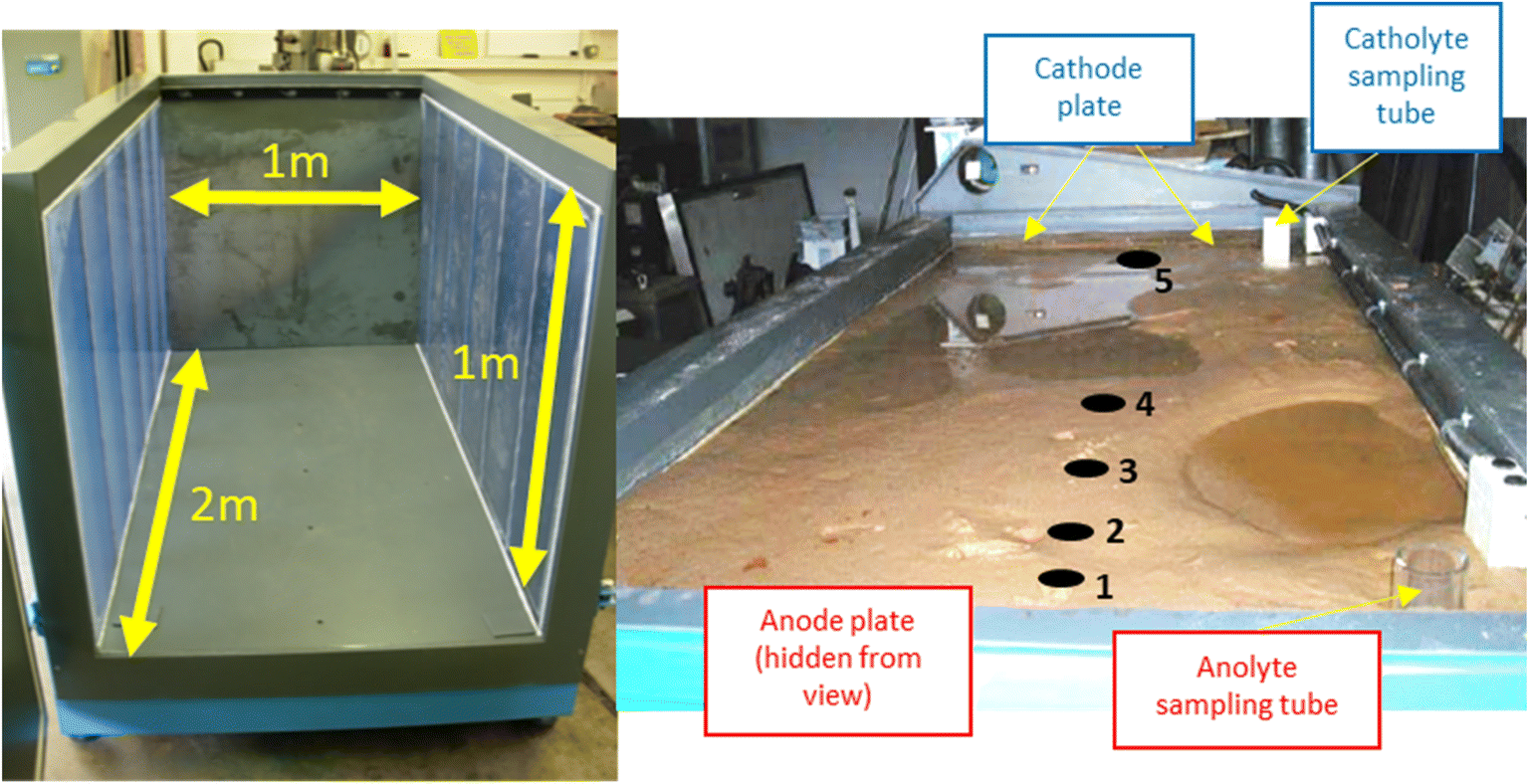 | ||
| Fig. 3 Left, dimensions of the empty cell with blue-tinted translucent Perspex® windows visible on either side of the cell; right, cell in operation with saturated sand. Cathode and anode electrode plates are highlighted, as are electrolyte sampling tubes. Electrolyte solution (1 Mm NaNO3) was added as necessary to anolyte or catholyte sampling tube to counter evaporation during the experiment. Numbers 1–5 indicate pH sampling sites at selected distances from the anode including, 10 cm, 30 cm, 45 cm, 80 cm, and 182 cm, respectively. A schematic complete with pH measurements is given in Fig. 5. | ||
Mild steel anodes and stainless steel cathodes were arranged as parallel plates, using a 50 V potential difference (0.25 V cm−1). Aliquots of electrolyte (1 L) were also taken from sampling tubes and the cell after the experiment concluded, to determine the pH of the electrolyte solution from selected points.
3. Results and discussion
3.1 Iron barrier growth
Iron barrier formation was observed in both real and simulated site materials, at both experimental scales (Sections 2.2–2.3). The time required to visually observe the first appearance of the iron barrier material reflected both the experimental scale and voltage applied, but also electrolyte strength: in the larger-scale experiment (2 m long, 50 V) iron barrier precipitation was observed after 6 weeks (42 days), while the bench-scale experiments showed iron barrier precipitation within 30 days (for higher ionic strength electrolytes – N. B. the effect of electrolyte strength on barrier growth rate and position is discussed further in Section 3.2).In the bench-scale cells, a sub-vertical iron-rich barrier was generated in all experiments, towards the anode side of the cell (3–30 mm from the anode – see Section 3.2). The iron barrier grown in the large cell was ca. 160 cm across, extending horizontally across four-fifths of the cell from the anode (Fig. 4 and 5). Significant amounts of material also formed at the bottom of the cell. In such a well-mixed, homogeneous and porous system this is probably the result of gravitational settling of iron precipitates, which in more heterogeneous systems would tend to accumulate at permeability/grain size boundaries, and/or enhanced electrode corrosion at depth (ref. Fig. 6). Data for pH, collected between sampling points 2 and 3 at the end of the experiment, confirm conditions are sufficiently alkaline (e.g. ≥pH ca. 6) to precipitate dissolved iron (Fig. 5). This follows the known redox chemistry of Fe2+, where, depending on the redox potential, a pH of between 5 and 7 is normally sufficient to cause precipitation.29 Galvanic corrosion of the plate electrodes from a pilot smaller-scale experiment (described in ESI†), shown in Fig. 6, provides additional insights into the mechanism of iron barrier growth.
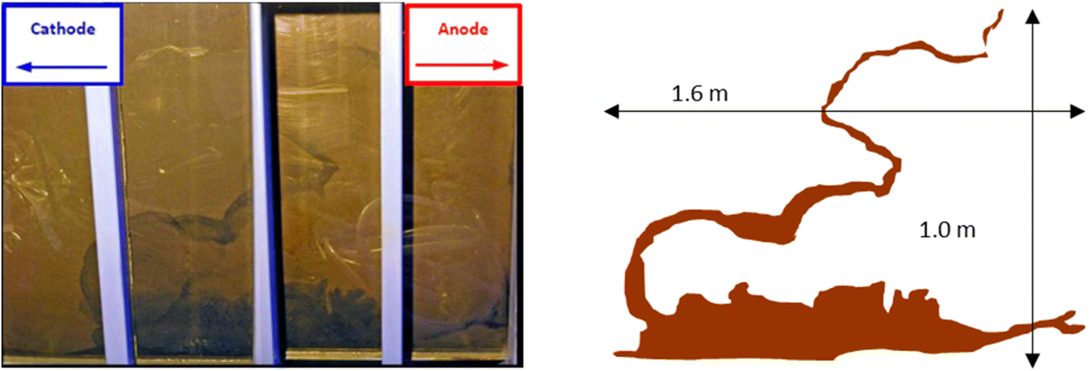 | ||
| Fig. 4 Left, view of the precipitated iron barrier through the Perspex® plastic sides of the large scale experiment; right, superimposable schematic of the iron barrier with approximate dimensions. | ||
 | ||
| Fig. 5 Extent of iron barrier formation across cell and pH measurements in the large-scale cell on day 160, the end of the experiment. See Fig. 3 for the cell in operation. | ||
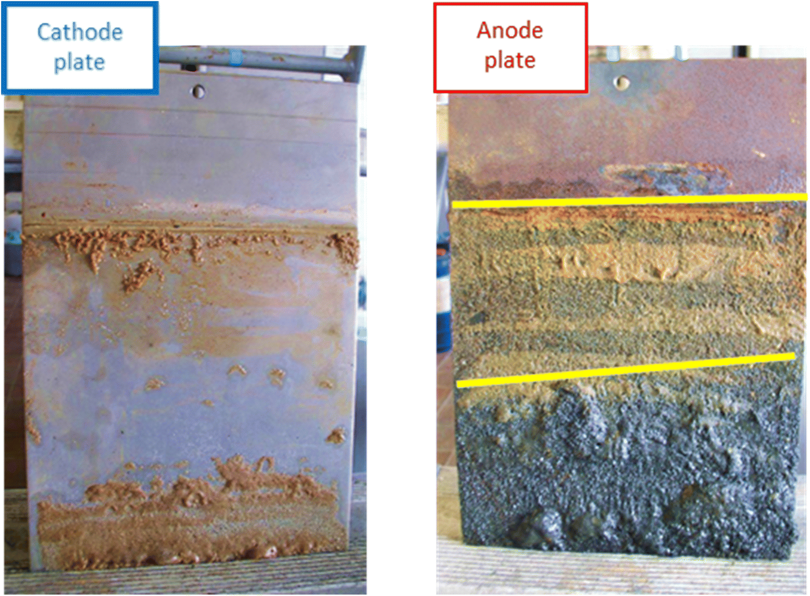 | ||
| Fig. 6 Cathode (left) and anode (right) plates from a pilot scale experiment (described in ESI†), conducted to inform set-up of the large-scale experiment, showing the difference in galvanic corrosion. The distinct bands of material are highlighted on the anode with yellow lines. Dimensions: LWH 0.2 × 28 × 18 cm. | ||
The extent of corrosion is clearly visible, with two distinct bands formed below the level of electrolyte saturation. Iron (electro)chemistry in oxic, anoxic and hypoxic environments is complex. Possible reactions for the initial electro-corrosion of Fe(s) from the electrodes and subsequent oxidation and selected thermodynamic data are given in Table 1.30
| 1 | Fe0(s) + H2O → Fe2+O + H2(g) | ΔGθ = −14.3 kJ mol−1 | ΔSθ = +94.2 J K−1 mol−1 |
| 2 | Fe0(s) + 2H2O → Fe2+(OH)2 + H2(g) | ΔGθ = −15.7 kJ mol−1 | ΔSθ = +51.4 J K−1 mol−1 |
| 3 | Fe0(s) + 3H2O → Fe3+(OH)3 + 1.5H2(g) | ΔGθ = +6.4 kJ mol−1 | ΔSθ = +63.5 J K−1 mol−1 |
| 4 | 2Fe0(s) + 3H2O → Fe3+2O3 + 3H2(g) | ΔGθ = −30.8 kJ mol−1 | ΔSθ = +215.0 J K−1 mol−1 |
| 5 | 3Fe2+(OH)2(s) → (Fe3+2, Fe2+)O4 + 2H2O + H2(g) Schikorr reaction | ΔGθ = −19.7 kJ mol−1 | ΔSθ = +152.2 J K−1 mol−1 |
| 6 | 2Fe3+(OH)3(s) → Fe3+2O3 + 3H2O | ΔGθ = −43.6 kJ mol−1 | ΔSθ = +88.1 J K−1 mol−1 |
| 7 | 4Fe2+(aq) + O2(aq) + 4H+ → 4Fe3+ + 2H2O | ΔGθ = −177.4 kJ mol−1 | n.r. |
The electrode potentials for both oxidation processes are Fe0(s) → Fe2+, E° = +0.447 V vs. SHE, and Fe2+ → Fe3+, E° = −0.771 V vs. SHE.32 Once leached ferrous (Reaction 1, Table 1) and ferric (Reaction 2, Table 1) iron is electromigrated towards the cathode, along the pH gradient, it eventually precipitates as, for example, magnetite (Fe3O4) through anaerobic corrosion in the Schikorr reaction (Reaction 5, Table 1). Electrochemically deposited magnetite at the surfaces of steel anodes may form in this way.33–35 Given the historical and industrially sensitive nature of this work (performed under license in 2006) we do not have access to X-ray analysis on the resulting solids. In our view, however, the chemistry and therefore the likely phase mineralogy is not dissimilar from previous work by Cundy,6 and Faulkner,9 where X-ray diffraction showed that goethite, magnetite (and/or maghemite), lepidocrocite and other, amorphous iron (oxy)hydroxides were present, at modal abundances of up to 20%. In the bench-scale experiments, magnetite, haematite and maghemite were detected in the precipitated barrier material, although presence (or otherwise) of other Fe-rich phases could not be conclusively determined (based on authors' unpublished X-ray diffraction data).
The bench-scale and large-scale experiments show similar trends in current measurement over time (Fig. 7), whereby increases in current following addition of electrolyte are superimposed on a general decline in current over time, observed in both experimental systems.
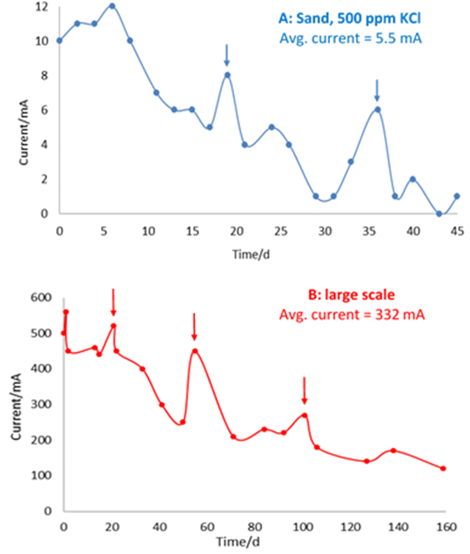 | ||
| Fig. 7 A (top) and B (bottom) – Amperometry for cell with 500 ppm KCl in sand (top, “A”) and large-scale experiment (bottom, “B”). Vertical arrows indicate addition of electrolyte and corresponding current increase. Avg. is average. | ||
This general decline in current over time is consistent with iron barrier formation, as growth of the (impermeable) deposits retards hydraulic (and ion) flow in the cells. This is in line with previous observations on a drop of initial current from 0.74 A to 0.14 A by Faulkner et al. in a 40 × 20 × 5 cm cell containing siliciclastic sand on application of a 3 V electric field over 19 days.9 Notably, in this earlier paper, deliberate rupturing of the iron barrier led to an increase in current and subsequent regrowth/resealing of the barrier, indicating that the precipitated barrier can “self-heal” due to the re-established flow path between opposite polarity electrodes created by the rupture.
3.2 Effect of electrolyte on iron barrier growth, and barrier growth rate
Bench experiments undertaken with different electrolytes (but with constant voltage) show a clear dependence of barrier formation time on electrolyte strength. Fig. 8 shows the time taken to first observe the iron barrier, as well as the time taken to reach a 10 mm barrier thickness, which we consider sufficient thickness to reduce ground permeability and thus inhibit water flow at scale. The figure shows the temperature-adjusted electrical conductivity values for the 20, 100 and 500 ppm solutions, and tap water. No barrier formation was observed in the control experiments.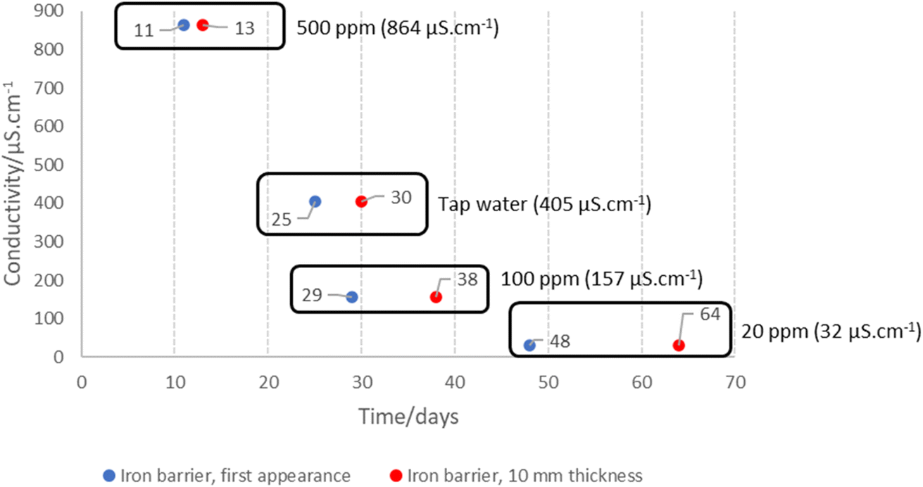 | ||
| Fig. 8 Electrolyte electrical conductivity and time taken to first observe (in blue) the iron barrier material, and time taken to reach 10 mm thickness (red). The number of days is represented next to each data point, with common data points for each solution and the corresponding conductivity also highlighted. With 100 ppm KCl electrolyte, an average current of 1 mA was recorded, increasing to 2 mA for the tap water and 4 mA for the 500 ppm KCl electrolyte. No current (e.g. 0 mA) was recorded for the 20 ppm KCl electrolyte or controls (deionized water, tap water, 500 ppm KCl; no voltage), presumed to be below the detection threshold of our amperometer (1 mA resolution and detection threshold). For ease of visualisation, conductivity (the known variable) is plotted here on the y-axis, and time, the unknown variable, on the x-axis. | ||
Higher electrolyte ionic strength leads to faster iron barrier growth due to enhanced corrosion and more rapid electrolysis. This is not surprising, as electrolytes of higher ionic strength are well-known to increase the soil current of an EKR deployment (e.g., Li et al. and refs. therein).36 Zakowski et al. have previously reported (2014) that higher salinities lead to enhanced corrosion rates of steel electrodes,37 and the effect of higher salinities on increased corrosion rates of mild and other steels has been reported.38,39 Here, for both the first appearance of the iron barrier and the time taken to grow to 10 mm, this effect is replicated, with the 500 ppm KCl electrolyte causing appearance of an iron barrier after 11 days, vs. 48 days for the 20 ppm KCl electrolyte (Fig. 8). Electrolyte strength also shifts the distance from the anode at which the iron barrier is precipitated; Fig. 9 shows the distance from the anode at which iron barriers form with each electrolyte used.
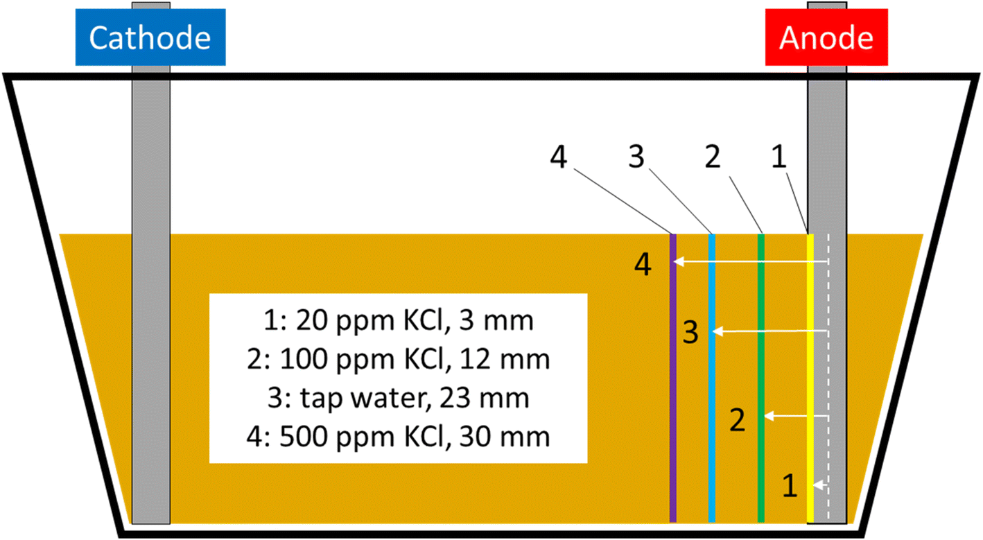 | ||
| Fig. 9 Scaled schematic of the EKR test cells with lines showing distance from anode at which iron barrier material was first observed; 1 = 20 ppm KCl electrolyte, 2 = 100 ppm KCl electrolyte, 3 = tap water electrolyte, 4 = 500 ppm KCl electrolyte. | ||
To investigate the iron barrier growth rate further, we examined barrier growth over time in the cell containing 500 ppm KCl electrolyte, Fig. 10. This was the cell with the highest average current and so most convenient to study over realistic experimental timescales.
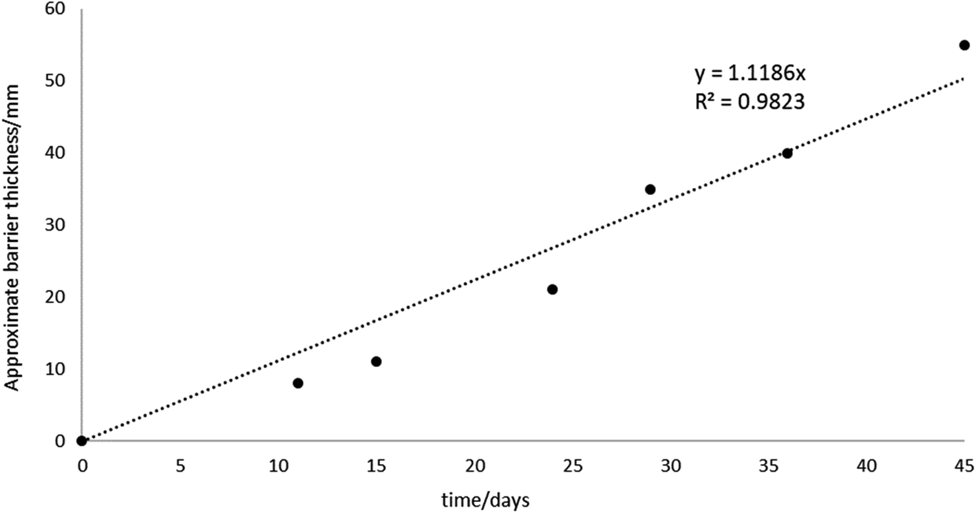 | ||
| Fig. 10 Barrier growth over time, showing a strong correlation (R2 = 0.98) between barrier thickness and time over which voltage is applied to the system (1.25 kg sand, LWH = 19 × 13 × 9 cm cells, 500 ppm KCl electrolyte at 10 V, or 0.53 V cm−1). | ||
For the cell with 500 ppm KCl electrolyte the final thickness of the iron barrier after 45 days was 55 mm at the thinnest point, extending 85 mm from the anode (cf. half of the 17 cm interelectrode gap). Further, a thickness (21 mm) of iron barrier precipitated after only 24 days with this low voltage. As shown in Fig. 10, in our test system an iron barrier grows at a little over 1 mm per day (1.12 mm day−1 with R2 correlation of 0.98). This is the first detailed examination of the growth rate of electrokinetically-grown iron barriers that we are aware of, and work is underway in our laboratories to expand both the scope and scale of these tests.
3.3 Power requirements and cost for scalable in situ barriers
The power, electricity and cost required to grow an iron barrier in each cell are given below in Table 2. This includes all small- and larger-scale experiments performed (Sections 2.2–2.3).| Electrolyte/experiment | Currenta/A | Power/W | Barrier appearance/days | Electricity consumed/kW h | ||
|---|---|---|---|---|---|---|
| First | To 10 mm | First appearance | To 10 mm | |||
| Controls | No corrosion observed | |||||
| a Notes: average current measured across duration of experiments, to nearest mA. b Current for 20 ppm KCl electrolyte cell was consistently displayed as “0.000 A”, presumed below the detection limit of our amperemeter. c 10 V over time in 19 cm long cell, variable electrolyte. d 50 V, 200 cm long cell, 1 mM NaNO3 electrolyte. e Not reported or no data available. Power consumption was estimated from the voltage (given above), multiplied by the average current for each experiment (e.g., P = VI; P is power, V is voltage and I is current). | ||||||
| 20 ppm KClc | —b | —b | 48 | 64 | —b | —b |
| 100 ppm KClc | 0.001 | 0.01 | 29 | 38 | 0.007 | 0.009 |
| Tap waterc | 0.002 | 0.02 | 25 | 30 | 0.012 | 0.014 |
| 500 ppm KClc | 0.004 | 0.04 | 11 | 13 | 0.011 | 0.013 |
| Large scaled | 0.332 | 16.6 | 42 | —e | 16.733 | —e |
Based on these experiments and calculations EKR and in situ barrier formation could easily be scaled accordingly to much larger cells or systems. With inexpensive electrode materials and low power consumption, the setup and running costs of EKR are low, as demonstrated by Agnew et al. using 2011 figures where the treatment cost of Pu-contaminated soil was £1700 m−3 using EKR. This was in comparison to a cost of ca. £5000 m−3 for direct removal (excavation and disposal).40
Here, for the largest scale experiment (50 V, 200 cm length, 0.25 V cm−1, Section 2.3) the total power consumed to first observe the iron barrier material is 16.6 W (from 0.332 A average current multiplied by 50 V) multiplied by 1008 hours (42 days). This gives a total electricity consumption of 16.7 kW h. Taking an average industrial electricity price in the UK of £0.11 per kW h for 2019,41 this equates to just £1.84 (increasing to £4.17 if rates consistent with the 2021–2022 energy crisis are used); for the USA at average 2020 industrial prices of $0.07 per kWh, this is $1.17.42 Even extending this out over the full duration of 160 days (3840 hours; 63.74 kW h), this still only equates to £7.01 or $4.46. By our estimation, therefore, the cost of electricity to successfully operate metre-plus scale cells for months is small, not more than single-digit or perhaps tens of GBP (£) or USD ($). The chief cost in our view is labor, and compared to conventional techniques such as excavation, much less labor is required to install and maintain EKR treatment cells. Consequently, we believe EKR combined with in situ barrier precipitation to be comparatively cost-competitive to existing techniques, although further work is needed on power consumption in scaled, in situ, systems.
4. Concluding remarks, further research requirements, and wider application
The data presented here clearly demonstrate that the deliberate generation of iron-rich barriers, grown from anode dissolution in real and simulated nuclear site materials, is feasible at up to and including the metre scale. We have demonstrated that barrier growth occurs over realistic timescales (days to months) at low voltages (typically <1 V cm−1) and electrolyte strengths, in realistic nuclear site media (simulated and real Sellafield site sands), through the deposition of environmentally ubiquitous non-hazardous ions (iron). Operating costs are inexpensive (e.g. tens of GBP/USD), and the system uses low-cost materials (mild steel). The system effectively mimics natural iron mineralization processes, where internal electric fields present in rock and soil bodies can generate multiple bands of ironstone via precipitation of Fe oxides and hydroxides.43 Further investigations on solutions containing environmentally-relevant concentrations of dissolved solids (32 – 864 μS cm−1) confirm that higher ionic strength electrolytes cause faster precipitation of iron-rich barriers, as expected from previous literature. These iron-rich materials and barriers are known to be sorptive, impermeable and useful in stabilizing soil.6 We have demonstrated that the use of high-energy systems is unnecessary for the growth of iron-rich barriers in soil subsurfaces and that, in fact, low energy systems are feasible. This is a key result, as ‘low intensity’ (<1 mA cm−2) cells are at worst environmentally benign (Gill et al. have previously assessed systems of this strength as having “no overall effect [on the microbial community]…”)44 and at best may actually facilitate enhanced land treatment (e.g. by increasing cellular metabolic rates).45 Although high-energy electrokinetic systems may increase growth rate of iron-rich barriers they consume considerable energy, and often damage soil quality (for example, through extreme pH gradients, unwanted electrolysis of water, soil heating, microbial cellular deformation, or increased contaminant cytotoxicity).46–48 The pH gradients generated in our test cells may inhibit soil bacterial activity close to the electrodes, but will dissipate following cessation of applied current, and where needed can be neutralized by polarity-switching at the electrodes at treatment termination, simulating methods used for pH regulation in existing electro-bioremediation approaches.49With this in mind we believe the work described (and previously published data) highlights the potential for the practical application of this technology for subsurface contaminant management or stabilisation at nuclear and other sites, via physical trapping, i.e. hydraulic containment via groundwater flow manipulation at scale, or contaminant adsorption on the in situ iron phases. For the former, in situ trials under realistic vadose zone and groundwater flow conditions are required to show full proof of concept, and for the latter, while Fe-rich phases are known to be effective sorbents for a range of common nuclear site contaminants (e.g. Tc, Pu, and others6), further work is needed on the mineralogy of the precipitated barrier, and mechanisms of sorption or incorporation of different radionuclides (and the reversibility of this), under realistic site and groundwater conditions. A further issue requiring attention is the management of pore water, and flow, which may be required to prevent back flow of contaminated fluids. Similarly, the in situ stability and longevity of the iron precipitates forming the barriers needs site-specific evaluation to inform local Safety Cases, particularly where varying soil pH and fluid flow conditions are expected (i.e. where reducing or acid flows may impact the barrier following its precipitation). The two experimental studies described here, however, clearly demonstrate that barrier generation is possible in realistic subsurface materials at existing sites, including the shallow sub-surface on the UK's Sellafield site. We have previously assessed the Technology Readiness Level (TRL) of EKR with in situ mineral precipitation at TRL 4–7,4 and the work described here reinforces this towards the higher end of this estimate; e.g., towards an operational prototype in real systems. Feasibility of extending the process to lower permeability clayey soils (for example, contaminated forest soils in the Fukushima exclusion zone) has also been shown.50
We also note recent advances in the use of sacrificial anodes for soil, groundwater and wastewater treatment,51 including iron12,52–54 magnesium,55 and aluminium.56,57 A range of problematic contaminants are known to reductively precipitate in the presence of reduced iron minerals and phases, or sorb to iron-rich phases (and other metal oxides and oxyhydroxides, including those of Al).54,58 This suggests further work on the chemistry and sorptive characteristics of electrokinetic barriers grown in authentic material should be a priority for further study, not only for iron, but also other commonly-occurring metals.
Author contribution
Jamie M. Purkis: conceptualization, methodology, validation, formal analysis, investigation, resources, data curation, writing – original draft, writing – review & editing, visualization, project administration. Frances Burrell: writing – review & editing, project administration. James R. Brydie: conceptualization, methodology, validation, formal analysis, investigation, resources, design, writing – review & editing, project administration. James Graham: writing – review & editing, project administration. Laurence Hopkinson: conceptualization, writing – review and editing. Andrew B. Cundy: conceptualization, methodology, resources, writing – review & editing, supervision, project administration, funding acquisition.Conflicts of interest
The authors declare no competing financial or personal interests that influence this work.Acknowledgements
The authors thank the NDA, NNL and predecessors as well as authors for kindly providing access to many reports described here. The authors also thank GAU-Radioanalytical at the University of Southampton for experimental support. Part of this work has been funded through the TRANSCEND (TRANsformative SCience and Engineering for Nuclear Decommissioning) consortium from the UK's Engineering and Physical Sciences Research Council, EPSRC (reference EP/S01019X/1). We also acknowledge support from the National Nuclear User Facility EXACT (Next Generation Accelerated Characterisation Technologies), via EPSRC grant EP/T011548/1. We thank two anonymous reviewers for comments that improved the overall discussion of the data presented and its wider implications.References
- Y. B. Acar, R. J. Gale, A. N. Alshawabkeh, R. E. Marks, S. Puppala, M. Bricka and R. Parker, Electrokinetic remediation: Basics and technology status, J. Hazard. Mater., 1995, 40, 117–137 CrossRef CAS.
- K. R. Reddy and S. Chinthamreddy, Electrokinetic remediation of heavy metal-contaminated soils under reducing environments, Waste Manag., 1999, 19, 269–282 CrossRef CAS.
- C. Cameselle and S. Gouveia, Electrokinetic remediation for the removal of organic contaminants in soils, Curr. Opin. Electrochem., 2018, 11, 41–47 CrossRef CAS.
- J. M. Purkis, P. E. Warwick, J. Graham, S. D. Hemming and A. B. Cundy, Towards the application of electrokinetic remediation for nuclear site decommissioning, J. Hazard. Mater., 2021, 413, 125274 CrossRef CAS PubMed.
- A. B. Cundy and L. Hopkinson, Method for Soil Remediation and Engineering, GB Patent, GB0222393D0, 2002.
- A. B. Cundy and L. Hopkinson, Electrokinetic iron pan generation in unconsolidated sediments: implications for contaminated land remediation and soil engineering, Appl. Geochem., 2005, 20, 841–848 CrossRef CAS.
- C. H. Lai, S. L. Lo and C. F. Lin, Mechanisms of iron oxide coating onto sand surface and its adsorption behaviors for copper, Toxicol. Environ. Chem., 1994, 46, 107–118 CrossRef CAS.
- B. Rusch, K. Hanna and B. Humbert, Coating of quartz silica with iron oxides: Characterization and surface reactivity of iron coating phases, Colloids Surf., A, 2010, 353, 172–180 CrossRef CAS.
- D. W. S. Faulkner, L. Hopkinson and A. B. Cundy, Electrokinetic generation of reactive iron-rich barriers in wet sediments: implications for contaminated land management, Mineral. Mag., 2005, 69, 749–757 CrossRef CAS.
- J. Shahabpour, Liesegang blocks from sandstone beds of the Hojedk Formation, Geomorphology, 1998, 22, 93–106 CrossRef.
- H. C. B. Hansen, Composition, stabilization, and light absorption of Fe(II)Fe(III) hydroxy-carbonate (‘green rust’), Clay Miner., 1989, 24, 663–669 CrossRef CAS.
- L. Hopkinson, A. B. Cundy, D. W. S. Faulkner, A. Hansen and R. Pollock, Electrokinetic stabilization of Cr(VI)-contaminated soils, in Electrochemical Remediation Technologies for Polluted Soils, Sediments and Groundwater, ed. K. Reddy and C. Cameselle, John Wiley and Sons, Inc., New York, 2009, ch. 8, pp. 179–193 Search PubMed.
- X. Li, L. Liu, Y. Wu and T. Liu, Determination of the Redox Potentials of Solution and Solid Surface of Fe(II) Associated with Iron Oxyhydroxides, ACS Earth Space Chem., 2019, 3, 711–717 CrossRef CAS.
- Y. Gossuin, J.-M. Colet, A. Roch, R. N. Muller and P. Gillis, Cesium Adsorption in Hydrated Iron Oxide Particles Suspensions: An NMR Study, J. Magn. Reson., 2002, 157, 132–136 CrossRef CAS PubMed.
- P. Trivedi and L. Axe, A Comparison of Strontium Sorption to Hydrous Aluminum, Iron, and Manganese Oxides, J. Colloid Interface Sci., 1999, 218, 554–563 CrossRef CAS PubMed.
- A. D. Ebner, J. A. Ritter and J. D. Navratil, Adsorption of Cesium, Strontium, and Cobalt Ions on Magnetite and a Magnetite–Silica Composite, Ind. Eng. Chem. Res., 2001, 40, 1615–1623 CrossRef CAS.
- C. I. Pearce, R. C. Moore, J. W. Morad, R. M. Asmussen, S. Chatterjee, A. R. Lawter, T. G. Levitskaia, J. J. Neeway, N. P. Qafoku, M. J. Rigali, S. A. Saslow, J. E. Szecsody, P. K. Thallapally, G. Wang and V. L. Freedman, Technetium immobilization by materials through sorption and redox-driven processes: A literature review, Sci. Total Environ., 2020, 716, 132849 CrossRef CAS PubMed.
- D. Li and D. I. Kaplan, Sorption coefficients and molecular mechanisms of Pu, U, Np, Am and Tc to Fe (hydr)oxides: A review, J. Hazard. Mater., 2012, 243, 1–18 CrossRef CAS PubMed.
- E. J. O'Loughlin, S. D. Kelly, R. E. Cook, R. Csencsits and K. M. Kemner, Reduction of Uranium(VI) by Mixed Iron(II)/Iron(III) Hydroxide (Green Rust): Formation of UO2 Nanoparticles, Environ. Sci. Technol., 2003, 37, 721–727 CrossRef PubMed.
- D. C. Girvin, L. L. Ames, A. P. Schwab and J. E. McGarrah, Neptunium adsorption on synthetic amorphous iron oxyhydroxide, J. Colloid Interface Sci., 1991, 141, 67–78 CrossRef CAS.
- K. Nakata, S. Nagasaki, S. Tanaka, Y. Sakamoto, T. Tanaka and H. Ogawa, Sorption and reduction of neptunium(V) on the surface of iron oxides, Radiochim. Acta, 2002, 90, 665–669 CrossRef CAS.
- K. F. Smith, K. Morris, G. T. W. Law, E. H. Winstanley, F. R. Livens, J. S. Weatherill, L. G. Abrahamsen-Mills, N. D. Bryan, J. F. W. Mosselmans, G. Cibin, S. Parry, R. Blackham, K. A. Law and S. Shaw, Plutonium(IV) Sorption during Ferrihydrite Nanoparticle Formation, ACS Earth Space Chem., 2019, 3, 2437–2442 CrossRef CAS PubMed.
- B. E. Cowie, J. M. Purkis, J. Austin, J. B. Love and P. L. Arnold, Thermal and Photochemical Reduction and Functionalization Chemistry of the Uranyl Dication, [UVIO2]2+, Chem. Rev., 2019, 119, 10595–10637 CrossRef CAS PubMed.
- CRC Handbook of Chemistry and Physics, ed. W. M. Haynes, Taylor and Francis Group, Boca Raton, Florida, USA, 95th edn, 2015 Search PubMed.
- E. Lacasa, S. Cotillas, C. Saez, J. Lobato, P. Canizares and M. A. Rodrigo, Environmental applications of electrochemical technology. What is needed to enable full-scale applications?, Curr. Opin. Electrochem., 2019, 16, 149–156 CrossRef CAS.
- R. López-Vizcaíno, V. Navarro, M. J. Léon, C. Risco, M. A. Rodrigo, C. Sáez and P. Canizares, Scale-up on electrokinetic remediation: Engineering and technological parameters, J. Hazard. Mater., 2016, 315, 135–143 CrossRef PubMed.
- U.S. Geological Survey, Specific conductance, chap. A6.3 (Section A, National Field Manual for the Collection of Water-Quality Data), in U.S. Geological Survey Techniques and Methods, 2019, DOI:10.3133/tm9A6.3.
- J. Graham, MSSS GEMS Phase 2: Characterisation of Soils and Strontium Sorption Batch Testing, Report NNL 13224, National Nuclear Laboratory, NNL, 2015 Search PubMed.
- N. Takeno, Atlas of Eh-pH diagrams, Geological Survey of Japan Open File Report No.419, 2005 Search PubMed.
- A. Groysman, Corrosion for Everybody, Springer, Dordrecht, The Netherlands, 2010 Search PubMed.
- Standard Potentials in Aqueous Solutions, ed. A. J. Bard, R. Parsons and J. Jordan, International Union of Pure and Applied Chemistry, IUPAC, and Marcel Dekker, Inc., New York, USA/Basel, Switzerland, 1985 Search PubMed.
- D. A. Jones, Principles and Prevention of Corrosion, Pearson Eductation, 2nd edn, 2001 Search PubMed.
- L. Cabrera, S. Gutierrez, N. Menendez, M. P. Morales and P. Herrasti, Magnetite nanoparticles: Electrochemical synthesis and characterization, Electrochim. Acta, 2008, 53, 3436–3441 CrossRef CAS.
- A. Rodríguez-López, A. Paredes-Arroyo, J. Mojica-Gomez, C. Estrada-Arteaga, J. J. Cruz-Rivera, C. G. Elías Alfaro and R. Antaño-López, Electrochemical synthesis of magnetite and maghemite nanoparticles using dissymmetric potential pulses, J. Nanopart. Res., 2012, 14, 993 CrossRef.
- M. Starowicz, P. Starowicz, J. Żukrowski, J. Przewoźnik, A. Lemański, C. Kapusta and J. Banaś, Electrochemical synthesis of magnetic iron oxide nanoparticles with controlled size, J. Nanopart. Res., 2011, 13, 7167–7176 CrossRef CAS PubMed.
- D. Li, X.-Y. Tan, X.-D. Wu, C. Pan and P. Xu, Effects of electrolyte characteristics on soil conductivity and current in electrokinetic remediation of lead-contaminated soil, Sep. Purif. Technol., 2014, 135, 14–21 CrossRef CAS.
- K. Zakowski, M. Narozny, M. Szocinski and K. Darowicki, Influence of water salinity on corrosion risk—the case of the southern Baltic Sea coast, Environ. Monit. Assess., 2014, 186, 4871–4879 CrossRef CAS PubMed.
- R. E. Melchers, Predicting long-term corrosion of metal alloys in physical infrastructure, npj Mater. Degrad., 2019, 3, 4 CrossRef.
- Z. Zeng, R. S. Lillard and H. Cong, Effect of Salt Concentration on the Corrosion Behavior of Carbon Steel in CO2 Environment, Corrosion, 2016, 72, 805–823 CrossRef CAS PubMed.
- K. Agnew, A. B. Cundy, L. Hopkinson, I. W. Croudace, P. E. Warwick and P. Purdie, Electrokinetic remediation of plutonium-contaminated nuclear site wastes: Results from a pilot-scale on-site trial, J. Hazard. Mater., 2011, 186, 1405–1414 CrossRef CAS PubMed.
- https://www.gov.uk/government/statistical-data-sets/international-industrial-energy-prices, (accessed 23rd November 2020).
- U. S. E. I. Administration, Monthly Electric Power Industry Report, Report Form EIA-861M, 2020 Search PubMed.
- K.-H. Jacob, S. Dietrich, H.-J. Krug, Self organised mineral fabrics. in Fractals and Dynamic Systems in Geoscience, ed. J. H. Kruhl, Springer-Verlag, Berlin, 1996, pp. 259–268 Search PubMed.
- R. T. Gill, M. J. Harbottle, J. W. N. Smith and S. F. Thornton, Electrokinetic-enhanced bioremediation of organic contaminants: A review of processes and environmental applications, Chemosphere, 2014, 107, 31–42 CrossRef CAS PubMed.
- N. Velasco-Alvarez, I. Gonzalez, P. Damian-Matsumura and M. Gutierrez-Rojas, Enhanced hexadecane degradation and low biomass production by Aspergillus niger exposed to an electric current in a model system, Bioresour. Technol., 2011, 102, 1509–1515 CrossRef CAS PubMed.
- J. C. Thrash and J. D. Coates, Review: Direct and Indirect Electrical Stimulation of Microbial Metabolism, Environ. Sci. Technol., 2008, 42(11), 3921–3931 CrossRef CAS PubMed.
- Q. Luo, X. Zhang, H. Wang and Y. Qian, Mobilization of phenol and dichlorophenol in unsaturated soils by non-uniform electrokinetics, Chemosphere, 2005, 59(9), 1289–1298 CrossRef CAS PubMed.
- G. Lear, M. J. Harbottle, G. Sills, C. J. Knowles, K. T. Semple and I. P. Thompson, Impact of electrokinetic remediation on microbial communities within PCP contaminated soil, Environ. Pollut., 2007, 146, 139–146 CrossRef CAS PubMed.
- Q. Luo, X. Zhang, H. Wang and Y. Qian, The use of non-uniform electrokinetics to enhance in situ bioremediation of phenol-contaminated soil, J. Hazard. Mater., 2005, 121, 187–194 CrossRef CAS PubMed.
- J. M. Purkis, A. Tucknott, I. W. Croudace, P. E. Warwick and A. B. Cundy, Enhanced electrokinetic remediation of nuclear fission products in organic-rich soils, Appl. Geochem., 2021, 125, 104826 CrossRef CAS.
- J. Deborde, P. Refait, P. Bustamante, C. Caplat, O. Basuyaux, A.-M. Grolleau, M.-L. Mahaut, C. Brach-Papa, J.-L. Gonzalez and S. Pineau, Impact of Galvanic Anode Dissolution on Metal Trace Element Concentrations in Marine Waters, Water, Air, Soil Pollut., 2015, 226, 423 CrossRef.
- A. A. G. D. Amarasooriya and T. Kawakami, Electrolysis removal of fluoride by magnesium ion-assisted sacrificial iron electrode and the effect of coexisting ions, J. Environ. Chem. Eng., 2019, 7, 103084 CrossRef CAS.
- M. Kobya, E. Demirbas and A. Akyol, Electrochemical treatment and operating cost analysis of textile wastewater using sacrificial iron electrodes, Water Sci. Technol., 2009, 60, 2261–2270 CrossRef CAS PubMed.
- J. Kumpiene, K. Engstrom, A. Pinedo Taquia, I. Carabante and J. Bjuhr, Arsenic immobilisation in soil using electricity-induced spreading of iron in situ, J. Environ. Manage., 2023, 325, 116467 CrossRef CAS PubMed.
- D. J. Kruk, M. Elektorowicz and J. A. Oleszkiewicz, Struvite precipitation and phosphorus removal using magnesium sacrificial anode, Chemosphere, 2014, 101, 28–33 CrossRef CAS PubMed.
- A. Loukanov, N. El Allaoui, A. Omor, F. Z. Elmadani, K. Bouayad and S. Nakabayashi, Large-scale removal of colloidal contaminants from artisanal wastewater by bipolar electrocoagulation with aluminum sacrificial electrodes, Results Chem., 2020, 2, 100038 CrossRef CAS.
- N. El Allaoui, A. Omor, F. Z. Elmadani, K. Bouayad, S. Nakabayashi and A. Loukanov, Semi-industrial remediation of effluents polluted by the artisanal activities through bipolar electrocoagulation with aluminum sacrificial electrodes, Water Environ. J., 2020, 34(S1), 831–840 CrossRef CAS.
- L. Onnby, C. Svensson, L. Mbundi, R. Busquets, A. B. Cundy and H. Kirsebom, g-Al2O3-based nanocomposite adsorbents for arsenic(V) removal: assessing performance, toxicity and particle leakage, Sci. Total Environ., 2014, 473–474, 207–214 CrossRef PubMed.
Footnote |
| † Electronic supplementary information (ESI) available. See DOI: https://doi.org/10.1039/d2va00308b |
| This journal is © The Royal Society of Chemistry 2023 |