DOI:
10.1039/D3TC01305G
(Paper)
J. Mater. Chem. C, 2023,
11, 8480-8485
Semi-transparent organic solar cells based on large bandgap star-shaped small molecules as mixed donors with PM6†‡
Received
13th April 2023
, Accepted 23rd May 2023
First published on 30th May 2023
Abstract
Semi-transparent organic solar cells (ST-OSCs) require carefully selected active layer materials and one key requirement, the average visible transmittance (AVT), can be optimised through an engineering strategy by choosing appropriate donors and acceptors. Herein, an efficient ternary active layer is fabricated by using two wide bandgap (3.0 eV) star-shaped small molecules BFN or BFSN and a middle bandgap polymer PM6 as mixed donors, and a narrow bandgap non-fullerene Y6 as acceptor. By controlling the ratio of BFN or BFSN and PM6, the AVT of films can be optimised without changing the thickness. Without optical engineering, compared to an AVT of 26% in the binary active layer (PM6![[thin space (1/6-em)]](https://www.rsc.org/images/entities/char_2009.gif) :Y6 = 1.3:1.5), the ternary active layers with BFN/BFSN:PM6:Y6 = 0.65:0.65:1.5 display a higher AVT of 60% and 62%, respectively, at a thickness of 100 nm. By further increasing the ratio of BFN/BFSN in the active layer, the AVT of ternary active films based on BFN/BFSN:PM6:Y6 = 1:0.3:1.5 at 100 nm thickness can reach 67%. The ternary ST-OSC based on BFN and BFSN in a ratio of 0.65 provides a comparable power conversion efficiency (PCE) of 10.01% (BFN) and 11.18% (BFSN) to 12.81% for the PM6:Y6 binary OSCs after a silver electrode deposition. However, in a higher blended ratio of BFN or BFSN (BFN/BFSN:PM6:Y6 = 1:0.3:1.5), the PCE shows a significant decrease due to the morphology of the active layer, which shows that the components are less well mixed. It was also noted that BFSN-based ternary ST-OSCs offer higher PCE than BFN-based ST-OSCs because of higher hole mobility for BFSN compared to BFN.
:Y6 = 1.3:1.5), the ternary active layers with BFN/BFSN:PM6:Y6 = 0.65:0.65:1.5 display a higher AVT of 60% and 62%, respectively, at a thickness of 100 nm. By further increasing the ratio of BFN/BFSN in the active layer, the AVT of ternary active films based on BFN/BFSN:PM6:Y6 = 1:0.3:1.5 at 100 nm thickness can reach 67%. The ternary ST-OSC based on BFN and BFSN in a ratio of 0.65 provides a comparable power conversion efficiency (PCE) of 10.01% (BFN) and 11.18% (BFSN) to 12.81% for the PM6:Y6 binary OSCs after a silver electrode deposition. However, in a higher blended ratio of BFN or BFSN (BFN/BFSN:PM6:Y6 = 1:0.3:1.5), the PCE shows a significant decrease due to the morphology of the active layer, which shows that the components are less well mixed. It was also noted that BFSN-based ternary ST-OSCs offer higher PCE than BFN-based ST-OSCs because of higher hole mobility for BFSN compared to BFN.
Introduction
Regarding fossil fuel depletion, organic solar cells (OSCs) are considered a promising and attractive replacement technology for obtaining renewable and affordable energy from sunlight, offering advantages in tuneable light-absorbing windows, lightweight devices, ease of manufacturing and non-toxicity.1–7 Based on the selection of light-absorbing materials in the active layer and deployment of transparent electrodes, semi-transparent organic solar cells (ST-OSCs) have an outstanding performance to generate electricity in certain light-absorbing windows whilst having a limited impact on the transmittance of the visible light.8,9 These unique characteristics enable ST-OSCs to be suitable candidates in some transparent application scenarios, such as building-integrated photovoltaics (BIPV), photovoltaic greenhouses, automobile glass, etc.10–14 Therefore, as a new technique to integrate energy conversion capability into daily applications, the future value of ST-OSCs is immeasurable.
In the field of OSCs, recent breakthroughs in high PCE of OSCs are based on middle bandgap (Eg) polymer donors (e.g., PCPDTFBT, PSBTBT and PM6, with Eg from 1.44 to 1.80 eV) in combination with non-fullerene acceptors (e.g., ITIC, IHIC, Y6, L8-BO and IT-4Cl with Eg from 1.33 and 1.59 eV).10,15–20 It makes sense to apply such active layers in the fabrication of ST-OSCs because of their high efficiency. For characterising the ST-OSCs, the average visible transmittance (AVT, typically based on the wavelength range of 370 to 780 nm) is another key parameter used to evaluate the performance of such devices. However, an inversely changing relationship between the PCE and AVT is commonly observed in the materials provided above. The AVT is mainly restricted by the absorption behaviours of the middle Eg polymer donors, whose strong absorption bands strongly overlap with the photopic response region of the human eye, reducing the AVT in a thick active layer. However, although a thin active layer can improve the AVT, it cannot meet the requirements of sufficient light absorption, resulting in an inferior PCE. Therefore, under the premise of maintaining the thickness of ST-OSCs, an ideal strategy for fabricating ST-OSC devices is to avoid visible photon-consuming polymer donors by using alternative materials. To achieve this goal, a strategy of fabricating ternary or quaternary ST-OSCs, using a wide bandgap (Eg) material as the second donor or host in the active layer, is commonly applied that allows visible light penetration and maintains sufficient thickness of the active layer. Most recently, Chen et al. used the 3.0 eV Eg fluorescent polymer FC-S1 as a host for PM6:Y6 solar cells. By adjusting the ratio to FC-S1:PM6:Y6-BO = 1:0.3:1.5, the devices achieved a PCE of 6.01% with an AVT of 49.28% in a 30 nm thick active layer.21 Xie et al. used the polymer PCDTBT as a host in PTB7-Th:IEICO-4Cl, which can be optimised to a PCE of 6.30% with an AVT of 43.93% in a film of 90 nm thickness.22 Instead of using wide Eg polymers as host or second donors, small molecules can also be used as donors to fabricate OSCs. Even though small molecular donors are rarely reported, some examples can be listed in binary OSCs containing chemical structures such as oligothiophene DRCN7T,23 and N,N′-diaryl-diamines.24 In ternary ST-OSCs, Huang et al. applied a small molecule, [2-(9-H-carbazol-9-yl)ethyl] phosphonic acid (2PACz) as an in situ self-organised hole transport interlayer and as a second donor, to achieve PEDOT-free ST-OSCs with a PCE of 15.2% and an AVT of 19.2%.25 In these strategies, the polymer and small molecules are utilised as hole-transport materials, demonstrating the feasibility of fabricating 2D/1A ternary ST-OSCs.
In our work, two large Eg (ca. 3.0 eV) star-shaped materials, tris(dihexyl-fluorenyl-N,N’-diaryl-amine)benzenes (BFN and BFSN, Fig. 1), were synthesised and employed as the second donor to give BFN/BFSN:PM6:Y6 ternary systems. At a film thickness of 100 nm, the ternary active layer, BFN/BFSN:PM6:Y6 = 0.65:0.65:1.5, achieved AVTs of 60% and 62%, respectively, with much higher transmittance than the PM6:Y6 binary film with an AVT of 26% with the same thickness. Furthermore, after the deposition of cathodes, the OSCs achieved PCEs of 10.01% and 11.18%, which represents only a slight decrease in PCE compared to a PCE of 12.81% in the binary PM6:Y6 devices. The results indicate that the ternary structures containing large Eg small molecule star-shaped donors are promising for high-performance ST-OSCs.
 |
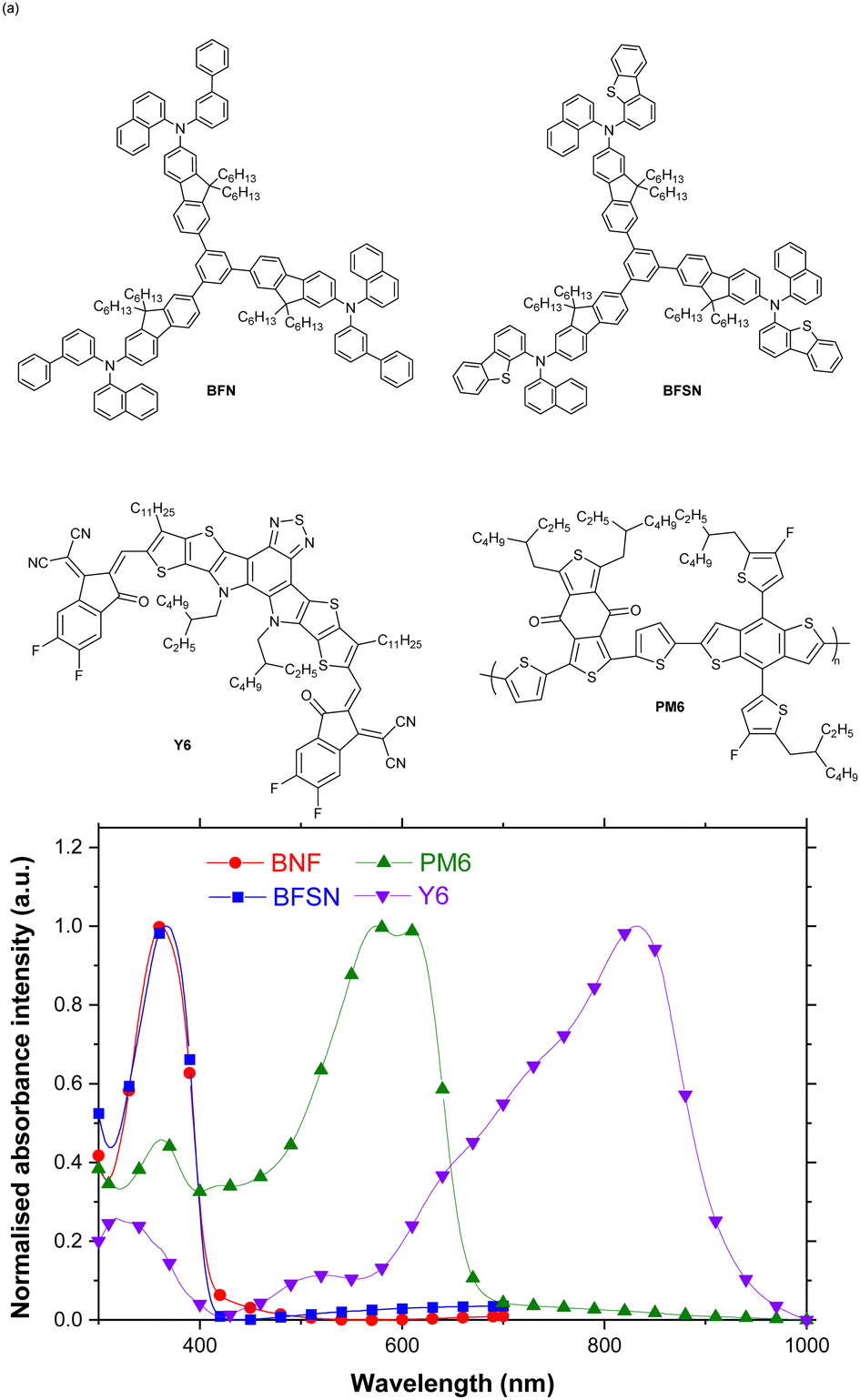
| | Fig. 1 (a) The chemical structures of BFN, BFSN, PM6 and Y6; (b) the normalised absorption spectra of BFN, BFSN, PM6 and Y6 films. | |
Results and discussion
The chemical structures and optical properties of active layer materials of OSCs
The chemical structures of BFN, BFSN, PM6 and Y6 are shown in Fig. 1a. The syntheses and characterisation of BFN and BFSN are provided in the experimental discussion and ESI.‡ The advantages of star-shaped organic semiconductor materials, and the reason for their selection for this work, include tunable and well-defined electronic properties, higher absorptivity compared to analogous linear compounds, excellent solubility and solution processability, and the ability to form high quality films because their film-forming properties are similar to polymers.26,27 The absorption spectra of BFN, BFSN, PM6 and Y6 films are shown in Fig. 1b. The film absorption of BFN and BFSN corresponds to a near UV band, with an absorption peak (λabs) at 366 nm and 368 nm, respectively, which defines the star-shaped monomers as wide bandgap materials with Eg of 3.0 eV. Such an absorption feature is beneficial for visible light to penetrate a ST-OSC. The polymer PM6 is a middle Eg (1.80 eV) donor, with strong absorption in the visible light region, whilst the non-fullerene acceptor Y6 shows near-IR absorption with λabs 820 nm and with an Eg of 1.33 eV.
Fig. 2 and Table 1 demonstrate the contribution of BFN and BFSN to the transmittance of a semi-transparent device. In a structure of ITO/PEDOT:PSS/ternary active layer structure, compared to the binary PM6:Y6 active layer structure in 100 nm thickness with an AVT of 26%, the AVTs of ternary active layers with the same thickness were improved to 60–67% by adjusting the ratio of BFN or BFSN:PM6:Y6 from 0.65:0.65:1.5 to 1:0.3:1.5 (Table 1). The transmittance of active layers is significantly improved when BFN and BFSN are used as second donors in the active layer. However, with a higher ratio of BFN and BFSN in blended films, the improvement of AVT is not so significant (an additional 5–7%).
 |
| | Fig. 2 The transmittance in the structure of ITO/PEDOT:PSS/ternary active layers. | |
Table 1 AVTs in the structure of ITO/PEDOT:PSS/ternary active layers
| Ternary active layer |
AVT (%) |
| PM6:Y6 = 1.3:1.5 |
26 |
| BFN:PM6:Y6 = 1:0.3:1.5 |
67 |
| BFSN:PM6:Y6 = 1:0.3:1.5 |
67 |
| BFN:PM6:Y6 = 0.65:0.65:1.5 |
60 |
| BFSN:PM6:Y6 = 0.65:0.65:1.5 |
62 |
The device performance of ternary OSCs
The device architecture is shown in Fig. 3a and the energy levels of the four materials used for the active layer are given in Fig. 3b. The energy levels of BFN and BFSN were determined by cyclic voltammetry (CV) (Table S1 and Fig. S10, ESI‡) using the same method used for the measurement of PM6 and Y6 in the literature.15 The highest occupied molecular orbital (HOMO) energy levels of BFN, BFSN, PM6, and Y6 are −5.12, −5.17, −5.45, and −5.65 eV whilst their lowest occupied molecular orbital (LUMO) energy levels are −2.08, −2.09, −3.65, and −4.10, eV, respectively. Therefore, an efficient energy level offset between the HOMO of PM6 and LUMO of Y6 can create exciton dissociation. However, it should be noted that the BFN and BFSN compounds also have the potential to form exciton dissociation in the ternary active layer.
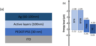 |
| | Fig. 3 (a) The device structure for the ternary OSCs. (b) The energy levels of the materials in the active layer. | |
In Table 2 and Fig. 4, the performance of the OSC devices is shown. As listed in Table 2, the device with the PM6:Y6 binary active layer with a thickness of 100 nm displays a PCE of 12.81%. In a ratio of BFN/BFSN:PM6:Y6 = 0.65:0.65:1.5, the PCE of devices is only slightly decreased to 10.01% and 11.18%. If the proportion of BFN and BFSN further increases to a ratio of BFN/BFSN:PM6:Y6 = 1:0.3:1.5, the performance of devices halves the efficiency to 5.34% and 6.06% for BFN and BFSN blended active layers, respectively.
Table 2 Device performance of ternary OSCs
|
|
V
oc (V) |
J
sc (mA cm−2) |
FF (%) |
PCE (%) |
| PM6:Y6 = 1.3:1.5 |
0.81 |
27.04 |
58.81 |
12.81 |
| BFN:PM6:Y6 = 1:0.3:1.5 |
0.86 |
10.65 |
57.97 |
5.34 |
| BFSN:PM6:Y6 = 1:0.3:1.5 |
0.85 |
13.17 |
53.99 |
6.06 |
| BFN:PM6:Y6 = 0.65:0.65:1.5 |
0.84 |
20.53 |
58.93 |
10.01 |
| BFSN:PM6:Y6 = 0.65:0.65:1.5 |
0.84 |
22.83 |
57.75 |
11.18 |
 |
| | Fig. 4 Device performance of ternary OSCs (a) J–V–L curves and (b) EQE spectra. | |
However, a slight increase of Voc was observed from 0.81 V for binary devices to 0.84–0.86 V for ternary devices by using BFN and BFSN as second donors. This could be due to a p–n heterojunction forming between BFN/BFSN and Y6, but this heterojunction is insufficient to compare it with the strong interaction between PM6 and Y6. The external quantum efficiency (EQE) spectra are shown in Fig. 4b. As the ratio of BFN or BFSN in the ternary active layer increases, the ternary device demonstrates lower photo-responses in the PM6 and Y6 absorbing region (Fig. S1, ESI‡), leading to lower Jsc in the ternary OSCs. It is worth noticing that there is only a mild decrease of EQE in the BFN and BFSN absorbing region (around 380 nm) when a high ratio of BFN and BFSN was used. It can be considered as evidence for exciton dissociation between BFN/BFSN and Y6.
Space-charged-limited current (SCLC) analysis
In Fig. 5, the hole mobility of BFN and BFSN by space-charge-limited current (SCLC) analysis is shown. After calculation, a difference in hole mobility in a BFSN film (5.22 × 10⁻⁵ cm2 V−1 s−1) and BFN film (3.02 × 10⁻⁶ cm2 V−1 s−1) was found, which explains the reason why a higher Jsc was measured in BFSN ternary OSCs compared to BFN ternary OSCs with the same device architecture. In comparing the structures of BFN and BFSN, we assume that the existence of the dibenzothiophene unit in BFSN provides better π–π stacking between molecules, leading to more efficient transport of charge carriers.28
 |
| | Fig. 5 Hole transport measurements by SCLC for BFN and BFSN. | |
Morphology characterisation
The film morphology of various ratios of BFN and BFSN blended films was characterised using atomic force microscopy (AFM) over a 2 × 2 um2 area. As displayed in Fig. 6, the neat film of PM6:Y6 presents a relatively smooth and uniform surface with a root-mean-squared roughness (Rq) of 5.43 nm. In a ratio of BFN/BFSN:PM6:Y6= 0.65:0.65:1.5, the morphology is similar to that of the non-blended binary film, with Rq of 4.18 nm and 8.18 nm for BFN and BFSN blended films, respectively. However, at a high ratio of BFN and BFSN blended films (BFN/BFSN:PM6:Y6 = 1:0.3:1.5), the Rq was dramatically increased to 39.8 nm and 21.2 nm for BFN and BFSN blended films, respectively. This indicates that in low-ratio blended BFN and BFSN films, the presence of BFN and BFSN has a limited effect on changing the morphology. However, in films with high-ratio BFN and BFSN films, the morphology is dominated by BFN and BFSN which could suffer from aggregation or crystallisation in films. As a consequence, a large leaking current can be generated, which, as we have observed, leads to a fall in PCE.
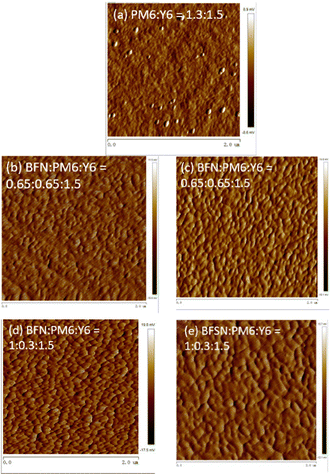 |
| | Fig. 6 AFM image for the BFN and BFSN blended PM6:Y6 active layer. | |
Experimental discussion.
Synthetic procedures for BFN and BFSN
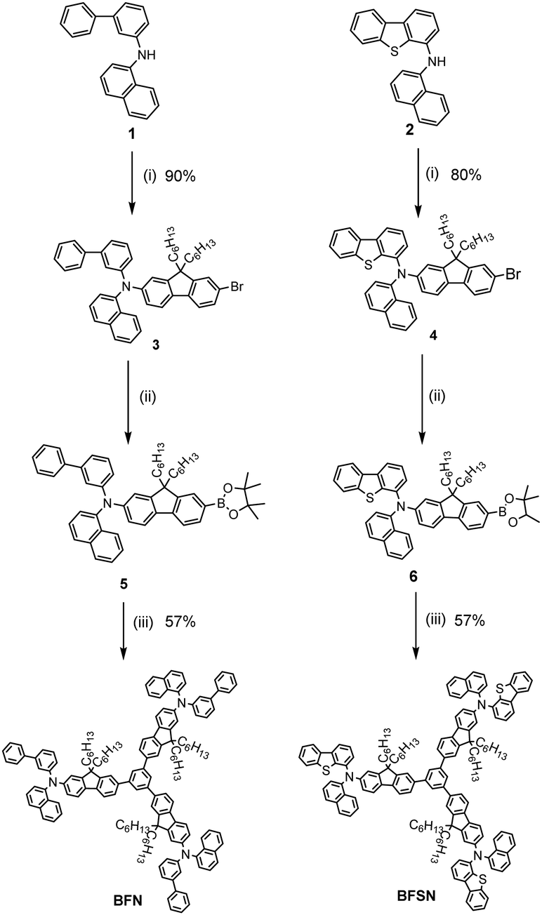
Two star-shaped donors, 1,3,5-tri(N-(naphthalene-1-yl)-N′-(1,1′-biphenyl-3-yl)-9,9′-dihexyl-2H-fluorene-2-yl-amine) benzene (BFN) and 1,3,5-tri(N-(naphthalene-1-yl)-N′-(dibenzothiophene-4-yl)-9,9′-2H-dihexylfluorene-2-yl-amine)benzene (BFSN) were synthesised from the route shown in Scheme 1. Compounds 1 and 2 were synthesised according to known procedures.29 Compounds 3 and 4 were synthesised via Buchwald–Hartwig amination and compound 5 and compound 6 were isolated after boronation and used without purification. Finally, the target compounds, BFN and BFSN, were obtained by Suzuki coupling with tribromobenzene, both in 57% yield. The structure and purity of all target compounds were confirmed and characterised by 1H and 13C NMR spectroscopies, mass spectrometry, thermogravimetric analysis (TGA), and differential scanning calorimetry (DSC), (Table S2 and Fig. S4–S9, ESI‡).
 |
| | Scheme 1 The synthetic route for the two novel star-shaped donor monomers: (i) 2,7-dibromo-9,9-dihexylfluorene, Pd2(dba)2, NaO-tBu, PPh3, toluene, 120 °C; (ii) 2-isopropoxy-4,4,5,5-tetramethyl-1,3,2-dioxaborolane, n-BuLi, THF, −78 °C; (iii) 1,3,5-tribromobenzene, Ba(OH)2·8H2O, Pd(PPh3)4, THF, H2O, 80 °C. | |
Ternary OSC devices fabrication
Ternary OSCs were fabricated by a spin-coating/evaporation hybrid method. Pre-patterned ITO slides (7 Ω sq−1, 15 mm × 15 mm × 1.1 mm, KINTEC) were cleaned with deionised water, acetone and isopropanol in an ultrasonic bath for 5 minutes before treatment with UV–ozone for 15 min. The architecture of the devices was ITO/PEDOT:PSS (30 nm)/active layer (100 nm)/Ag (60–100 nm). For all devices, the OSCs were fabricated using pre-cleaned indium-tin-oxide (ITO) coated glass substrates after ozone plasma treatment. PEDOT:PSS (Xi’an polymer light technology Corp, Al 4083) was spin-coated and annealed on a hotplate at 120 °C for 20 minutes. After the substrate cooled down to room temperature, the mixed solution of BFN or BFSN with PM6 and Y6 was spun at 1000 rpm from chloroform solution at a concentration of 10 mg ml−1. Ag was thermally evaporated using a Kurt J. Lesker Spectros II deposition system at 10−6 bar at a deposited rate of 1–1.5 Å s−1. A Keithley Semiconductor Characterisation System (SCS) 4200, Solar Simulator System Newport Oriel Sol3A (AM1.5) and QE-R Enlitech (EQE measurement) were used for the characterisation of the OSCs.
SCLC analysis
Space-charge-limited current behaviour can be described by the Mott-Guerney law:
Where J is the current density, ε is the dielectric constant, μ is the mobility, V is the voltage and L is the distance between the two electrodes (film thickness). The detailed experimental procedure is given in the ESI.‡
Summary
In conclusion, we have synthesised two amine-based hole-transport materials and introduced them as second donors into the active layer of ternary ST-OSCs. By adjusting the ratio of donors, BFN/BFSN:PM6:Y6 (0.65:0.65:1.5), PCEs of 10.01% and 11.18% were achieved in devices with an AVT of 60% and 62% before cathode deposition. Compared to the binary OSCs (PM6:Y6 = 1.3:1.5, PCE = 12.81%, and AVT = 26%), this is a significant improvement in AVT only with a small sacrifice in PCE. Further investigations revealed that BFSN has higher hole mobility than BFN, which leads to better performance (higher Jsc) in BFSN blended devices. In addition, by using a high ratio of BFN and BFSN in the active layer (BFN/BFSN:PM6:Y6 = 1:0.3:1.5), the morphology of active layers becomes detrimental to device performance, resulting in a huge decrease in PCE with only a slight increase in AVT. As an innovative attempt, our results suggest that the selection of appropriate donor mixtures in the active layer of OSCs is a potential direction for the development of desirable ST-OSCs. In recent work, the application of a wide bandgap polymer (2.20 eV) in ternary ST-OSCs gave a best performing device with a PCE of 10.01% and AVT of 30.48%.30 Given that there was only a 30% to 40% transmittance loss after depositing the ultrathin metal transparent electrode (UMTE),31–33 the estimated AVT after depositing UMTE for star-shaped BFN and BFSN in ternary ST-OSCs as wide bandgap materials has provided device characteristics that are very competitive in the field.
Conflicts of interest
There are no conflicts to declare.
Acknowledgements
The authors thank the Royal Society for financial support from the International Exchanges 2018 Cost Share scheme (UK and China, IEC\NSFC\181564), Shenzhen Hong Kong Innovation Circle Joint R&D Project (SGDX20190918105201704) Shenzhen Science and Technology Program (GJHZ20210705143400002). MY thanks the China Scholarship Council and the University of Glasgow for funding his PhD studies.
Notes and references
- K. Fukuda, K. Yu and T. Someya, Adv. Energy Mater., 2020, 10, 2000765 CrossRef CAS.
- P. R. Berger and M. Kim, J. Renewable Sustainable Energy, 2018, 10, 013508 CrossRef.
- L. Sun, K. Fukuda and T. Someya, npj Flexible Electron., 2022, 6, 89 CrossRef.
- Y. Tong, Z. Xiao, X. Du, C. Zuo, Y. Li, M. Lv, Y. Yuan, C. Yi, F. Hao, Y. Hua, T. Lei, Q. Lin, K. Sun, D. Zhao, C. Duan, X. Shao, W. Li, H.-L. Yip, Z. Xiao, B. Zhang, Q. Bian, Y. Cheng, S. Liu, M. Cheng, Z. Jin, S. Yang and L. Ding, Sci. China: Chem., 2020, 63, 758–765 CrossRef CAS.
- D. Luo, W. Jang, D. D. Babu, M. S. Kim, D. H. Wang and A. K. K. Kyaw, J. Mater. Chem. A, 2022, 10, 3255–3295 RSC.
- V. Piradi, G. Zhang, T. Li, M. Zhang, Q. Peng, X. Zhan and X. Zhu, ACS Appl. Mater. Interfaces, 2020, 12, 41506–41514 CrossRef PubMed.
- V. Piradi, X. Xu, Z. Wang, J. Ali, Q. Peng, F. Liu and X. Zhu, ACS Appl. Mater. Interfaces, 2019, 11, 6283–6291 CrossRef CAS PubMed.
- N. Schopp, V. V. Brus and T. Q. Nguyen, Adv. Opt. Mater., 2020, 9, 2001484 CrossRef.
- S. Han, Y. Deng, W. Han, G. Ren, Z. Song, C. Liu and W. Guo, Sol. Energy, 2021, 225, 97–107 CrossRef CAS.
- G. P. Kini, S. J. Jeon and D. K. Moon, Adv. Funct. Mater., 2021, 31, 2007931 CrossRef CAS.
- Y. Luo, X. Wang, M. Zhang, X. Sun, A. Saparbaev, S. Lei, J. Zhang, B. Xiao, C. Yang, Z. Liu and R. Yang, Sol. RRL, 2022, 6, 2200679 CrossRef CAS.
- Y. Li, X. Huang, H. K. M. Sheriff and S. R. Forrest, Nat. Rev. Mater., 2022, 8, 186–201 CrossRef.
- A. A. F. Husain, W. Z. W. Hasan, S. Shafie, M. N. Hamidon and S. S. Pandey, Renewable Sustainable Energy Rev., 2018, 94, 779–791 CrossRef CAS.
- I. Burgués-Ceballos, L. Lucera, P. Tiwana, K. Ocytko, L. W. Tan, S. Kowalski, J. Snow, A. Pron, H. Bürckstümmer, N. Blouin and G. Morse, Joule, 2021, 5, 2261–2272 CrossRef.
- J. Yuan, Y. Zhang, L. Zhou, G. Zhang, H.-L. Yip, T.-K. Lau, X. Lu, C. Zhu, H. Peng, P. A. Johnson, M. Leclerc, Y. Cao, J. Ulanski, Y. Li and Y. Zou, Joule, 2019, 3, 1140–1151 CrossRef CAS.
- W. Gao, F. Qi, Z. Peng, F. R. Lin, K. Jiang, C. Zhong, W. Kaminsky, Z. Guan, C. S. Lee, T. J. Marks, H. Ade and A. K. Jen, Adv. Mater., 2022, 34, e2202089 CrossRef PubMed.
- G. Zhang, J. Zhao, P. C. Y. Chow, K. Jiang, J. Zhang, Z. Zhu, J. Zhang, F. Huang and H. Yan, Chem. Rev., 2018, 118, 3447–3507 CrossRef CAS PubMed.
- J. Hou, O. Inganas, R. H. Friend and F. Gao, Nat. Mater., 2018, 17, 119–128 CrossRef CAS PubMed.
- Y. Cui, Y. Wang, J. Bergqvist, H. Yao, Y. Xu, B. Gao, C. Yang, S. Zhang, O. Inganäs, F. Gao and J. Hou, Nat. Energy, 2019, 4, 768–775 CrossRef CAS.
- Y. Zhang, J. Zou, C.-C. Cheuh, H.-L. Yip and A. K. Y. Jen, Macromolecules, 2012, 45, 5427–5435 CrossRef CAS.
- X. Liu, Z. Liu, M. Chen, Q. Wang, F. Pan, H. Liu, L. Zhang and J. Chen, Macromol. Rapid Commun., 2022, 43, e2200199 CrossRef PubMed.
- H. Tang, Y. Li, H. Liu, J. Wu, L. Chen, Y. Fu and Z. Xie, J. Mater. Chem. C, 2022, 10, 3720–3728 RSC.
- Q. Zhang, B. Kan, F. Liu, G. Long, X. Wan, X. Chen, Y. Zuo, W. Ni, H. Zhang, M. Li, Z. Hu, F. Huang, Y. Cao, Z. Liang, M. Zhang, T. P. Russell and Y. Chen, Nat. Photonics, 2014, 9, 35–41 CrossRef.
- M. L. Ball, Q. Burlingame, H. L. Smith, T. Liu, S. R. Parkin, A. Kahn and Y.-L. Loo, ACS Energy Lett., 2021, 7, 180–188 CrossRef.
- J. Jing, S. Dong, K. Zhang, Z. Zhou, Q. Xue, Y. Song, Z. Du, M. Ren and F. Huang, Adv. Energy Mater., 2022, 12, 2200453 CrossRef CAS.
- A. L. Kanibolotsky, N. Laurand, M. D. Dawson, G. A. Turnbull, I. D. W. Samuel and P. J. Skabara, Acc. Chem. Res., 2019, 52, 1665–1674 CrossRef CAS PubMed.
- A. L. Kanibolotsky, I. F. Perepichka and P. J. Skabara, Chem. Soc. Rev., 2010, 39, 2695–2728 RSC.
- C. Wang, H. Dong, H. Li, H. Zhao, Q. Meng and W. Hu, Cryst. Growth Des., 2010, 10, 4155–4160 CrossRef CAS.
- 2015.
- D. Xie, Y. Zhang, X. Yuan, Y. Li, F. Huang, Y. Cao and C. Duan, Adv. Funct. Mater., 2022, 33, 2212601 CrossRef.
- M. B. Upama, M. Wright, N. K. Elumalai, M. A. Mahmud, D. Wang, C. Xu and A. Uddin, ACS Photonics, 2017, 4, 2327–2334 CrossRef CAS.
- X. Li, R. Xia, K. Yan, J. Ren, H.-L. Yip, C.-Z. Li and H. Chen, ACS Energy Lett., 2020, 5, 3115–3123 CrossRef CAS.
- R. Betancur, P. Romero-Gomez, A. Martinez-Otero, X. Elias, M. Maymó and J. Martorell, Nat. Photonics, 2013, 7, 995–1000 CrossRef CAS.
|
| This journal is © The Royal Society of Chemistry 2023 |
Click here to see how this site uses Cookies. View our privacy policy here. 
 Open Access Article
 This Open Access Article is licensed under a
  *a and
Hong
Meng
*a and
Hong
Meng