DOI:
10.1039/D2TB02338E
(Paper)
J. Mater. Chem. B, 2023,
11, 1978-1986
Construction of a desirable hyperbolic microfluidic chip for ultrasensitive determination of PCT based on chemiluminescence†
Received
27th October 2022
, Accepted 26th January 2023
First published on 26th January 2023
Abstract
Since procalcitonin (PCT) is a specific inflammation indicator of severe bacterial inflammation and fungal infection, it is of great significance to construct a sensitive and rapid microfluidic chip to detect PCT in clinical application. The design of micromixers using a lab-on-a-chip (LOC) device is the premise to realizing the adequate mixing of analytical samples and reagents and is an important measure to improve the accuracy and efficiency of determination. In this research study, we investigate the mixing characteristics of hyperbolic micromixers and explore the effects of different hyperbolic curvatures, different Reynolds numbers (Re) and different channel widths on the mixing performance of the micromixers. Then, an optimal micromixer was integrated into a microfluidic chip to fabricate a desirable hyperbolic microfluidic chip (DHMC) for the sensitive determination of inflammation marker PCT with a limit of detection (LOD) as low as 0.17 ng mL−1via a chemiluminescence signal, which can be used as a promising real-time platform for early clinical diagnosis.
1 Introduction
Microfluidics is an interdisciplinary research direction integrating the fields of machinery, materials, biology and chemistry.1–4 With the advantages of high integration, small size and large specific surface area, microfluidics is used for micro-scale fluid dynamics research, such as microfluidic manipulation and actuation, particle separation, microdroplet generation, and drive.5–7 In addition, microfluidics is also employed in biomedical fields for biochemical assays. The micromixer, an important part of the microfluidic system, can efficiently mix reagents in a small volume to complete the biochemical analysis process, with fast reaction speed and low reagent consumption.8–10 Therefore, high throughput, low cost, and automation capability have made micromixers an important research direction for real-time detection technology.
Generally, micromixers are divided into active and passive mixers according to the different driving methods.11–13 Active mixers rely mainly on applied force fields to enable faster sampling and higher mixing efficiency.14–17 However, a typical drawback of this active mixing approach is the requirement for external instrumentation to provide the driving force, which undoubtedly increases the complexity of the structure of the micro-mixing system and increases the cost of detection. In contrast, passive micromixers only use the inertial forces caused by the fluid flow and microchannel structure to achieve mixing, which is simple, easy to manufacture, and highly integrated, and can better accommodate analytical instruments.18–20 It can be noted that bending micromixers use Dean vortices as a typical passive mixer, and lateral Dean flows in microchannels to enhance fluid mixing. Mashaei et al. constructed a new chaotic micro-mixer consisting of four consecutive non-planar arrangements of quadrant cells to investigate its flow characteristics and mixing efficiency numerically.21 Alam and Kim numerically investigated fluid mixing in microchannels with grooved sidewalls, and the grooved microchannels produced better mixing performance than smooth microchannels at Re greater than 10.22 In addition, the mixing performance was further enhanced as the distance between the baffles was reduced. Duryodhan et al. investigated the effect of Re and different aspect ratios on spiral micro-mixing channels.23 The mixing efficiency of spiral microchannels with higher aspect ratios was higher than those with smaller aspect ratios. Nivedita et al. provided the first experimental and numerical study of Dean flows in microchannels with Re > 100 while providing new insights into the study of secondary flow instabilities in low aspect ratio spiral microchannels.24–26 A Dean Vortex can improve the mixing performance of fluid, and the principle of the Dean Vortex effect can effectively focus particles or cells of various sizes in inertial microfluidics.27–29 Although the proposed micro-mixing structures in the above literature reports provide good mixing performance for fluid mixing, the mixing efficiency needs further improvement.
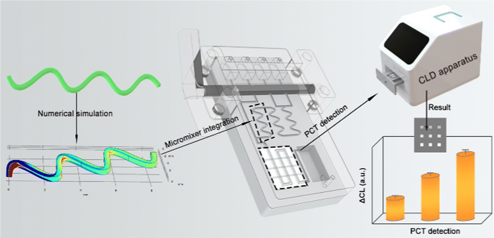
Herein, inspired and motivated by the abovementioned studies, a new type of passive micro-mixing structure using a hyperbola shape was proposed. In the investigation, the hyperbola-shaped micromixer curvatures were simulated by COMSOL Multiphysics to study the fluid flow characteristics and hybrid process of fluids.30–32 Notably, the mixing efficiency of the designed micromixer was obviously better than the above literature reports that introduced microchannels. Then, the optimal micro-mixing structure was integrated into a microfluidic chip to form a DHMC. Generally, PCT can reflect the activity of systemic inflammation reactions, which was a parameter of diagnosis and monitoring bacterial inflammatory disease infection.33–35 Therefore, the DHMC integration with chemiluminescence as signal readout enabled achieving the point-of-care testing (POCT) of PCT in the clinical diagnosis treatment (Scheme 1). Notably, the DHMC by simulation showed a high mixing efficiency for sample reagents, which can then improve the detection sensitivity. Meanwhile, the developed DHMCs were suitable for the early screening of inflammatory markers in remote areas, communities, and families, which can promote the new development of desirable microfluidic chips.36
 |
| | Scheme 1 Design of DHMC with high mixing efficiency and its application in PCT determination. | |
2 Experimental
2.1 Materials and apparatus
Procalcitonin (PCT), capture antibody for PCT (PCT-Ab1), and detection antibody for PCT conjugated to horseradish peroxidase (PCT-Ab2) were obtained from Abcam (UK). Bovine serum albumin (BSA) powder was purchased from Tianjin Kangyuan Biotechnology Co., Ltd (Tianjin, China). Extra ultra-sensitive ELC luminescent solution was purchased from Bio-sharp (Chongqing, China). Polydimethylsiloxane (PDMS) and the curing agent (Sylgard 184) were purchased from Dow Corning Corporation (Michigan, USA). The silica membrane was obtained from Shanghai Shentong Rubber & Plastic Products Co., Ltd (Shanghai, China).
Yangzhou YIXIN 3D Co., Ltd (Yangzhou, China) provided an AccuFab-L4K light-curing 3D printer used for the molds for PDMS chip fabrication. A 202-00T electric constant temperature drying oven and a DZF-6020A vacuum drying oven were purchased from Lichen BX Co., Ltd (Shanghai, China). The bonding of the micromixer and the PDMS chip were cleaned using a PTL-VM500 plasma cleaner from Shandong Putler Electric Technology Co., Ltd (Shandong, China). A CL image analysis system was obtained from BIO-OI Co., Ltd (Guangzhou, China).
2.2 Design and simulation of the micromixer
2.2.1 Structural design of the micromixer.
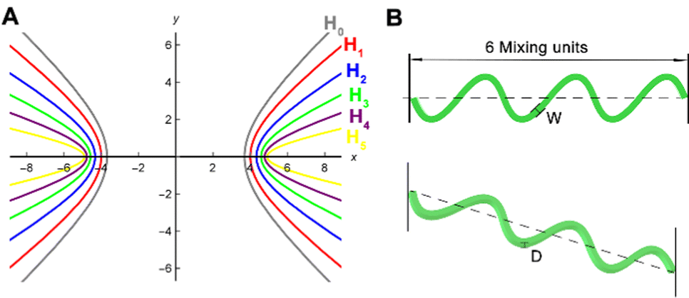
The hyperbolic micromixer used a single-hyperbolic curve as a cycle to form a micromixer channel structure. The six hyperbolas were designed according to different hyperbolic curvatures to study the relationship between different hyperbolic curvature radius (R) and mixing efficiency. As shown in Fig. 1A, the six hyperbolic curvatures R were 3.078, 2.25, 1.44, 0.87, 0.47, and 0.204, respectively.| |  | (1) |
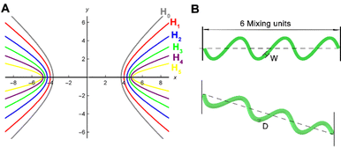 |
| | Fig. 1 (A) Schematic diagram of six hyperbolas. (B) Schematic diagram of a hyperbolic micromixer. | |
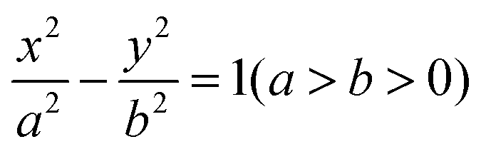
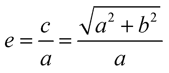
The arc length of each hyperbola was fixed at 3 mm, and six curves were defined according to the standard eqn (1) of the hyperbola, where a was the real semi-axis of the hyperbola, and b was the imaginary semi-axis. In general, the hyperbola can also be expressed by the eccentricity e, which was defined by eqn (2):
| |  | (2) |
Here,
c was half the focal length, and the defined value of
c was 5 for both hyperbolas. The hyperbolas were defined by changing the parameters of the real and imaginary semi-axes, which were: hyperbola H
0:
a = 3.69,
b = 3.37,
e0 = 1.36; H
1:
a = 4,
b = 3,
e1 = 1.25; H
2:
a = 4.33,
b = 2.5,
e2 = 1.16; H
3:
a = 4.58,
b = 2,
e3 = 1.092; H
4:
A = 4.77,
b = 1.5,
e4 = 1.05 and H
5:
a = 4.899,
b = 1,
e5 = 1.021.
Fig. 1B shows a schematic diagram of the hyperbolic micromixer. Six mixing units were selected to make one micromixer, where
W was the channel width and
D was the channel depth (
W =
D). In this case, we studied the relationship between different curvature
R and the mixing efficiency.
2.2.2 Numerical simulation and boundary conditions.
The micromixer model was simulated in COMSOL Multiphysics, and the numerical simulation was solved using a 3D model to obtain reliable results. To simplify the model, a steady-state fluid flow was assumed. The fluid flow state was laminar flow, and the boundary conditions of each channel wall were set to no slip. At the inlet, the boundary conditions were set to normal inflow velocity. At the outlet, the pressure conditions were set to zero static pressure and a suppressed backflow. Since it was an incompressible Newtonian fluid, the flow model can be described by three-dimensional Navier–Stokes equations and continuity equations,37,38 as shown in eqn (3) and (4):| | ∇·![[small nu, Greek, vector]](https://www.rsc.org/images/entities/i_char_e0ea.gif) = 0 = 0 | (3) |
where ρ was the fluid density, 9.97 × 10² kg m−3; was velocity vector; μ was dynamic viscosity, 0.9 × 10⁻³ Pa s; p was pressure. For the concentration field, the convection–diffusion equation was used for modelling and was expressed by eqn (5):| | | ∇C= D∇2C | (5) |
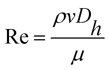
Here, C was the fluid concentration and D was the diffusion coefficient, 2.97 × 10⁻¹⁰ m2 s−1. When setting the inlet boundary conditions, the step function was used for dividing the concentrations of 0 and 1 mol L−1. The fluid flow characterization used Re, which was defined by eqn (6):| |  | (6) |
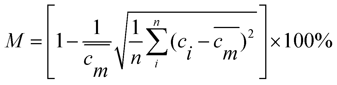
v was the fluid's average velocity, and Dh was the hydraulic diameter of the channel. The mixing efficiency M was obtained by calculating the standard deviation of the concentration mass fraction, which can be defined by formula (7). When M = 0 indicated that the fluid was not mixed, M = 1 indicated that the liquid was completely mixed.39| |  | (7) |
where c![[m with combining macron]](https://www.rsc.org/images/entities/i_char_006d_0304.gif) is mass fraction of the concentration of the liquid when it was completely mixed and ci the mass fraction of the concentration at each equal division.
is mass fraction of the concentration of the liquid when it was completely mixed and ci the mass fraction of the concentration at each equal division.
2.3 Fluid dynamics theory
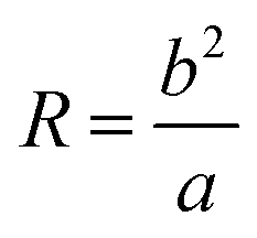
The eqn (8) can evaluate the strength of the Dean vortex using Dn.| |  | (8) |
where R is the radius of curvature of the channel, and the radius of curvature at the vertex of the hyperbola (a, 0) or (−a, 0) can be simplified to eqn (9).| |  | (9) |
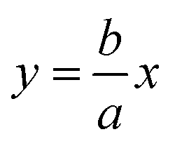
From eqn (8) and (9), the Dn was proportional to the Re in addition to the inversely proportional curvature radius. At the same time, the hyperbolic asymptotic eqn (10) explained that when the slope of the asymptote deviates to infinity, the slope was close to the perpendicular y-axis, and then Dn tended to 0. When the slope of the asymptote deviated to 0, the slope was close to the parallel x-axis, and then Dn tended to infinity.
| |  | (10) |
When either Re or Dn was very low, there was almost no vortex intensity at the cross-section; with the increase of Re and the decrease of the curvature radius R, the larger Dn was, the higher the visibility of the vortex intensity was. The Dn was proportional to the Re except for the inversely proportional curvature radius.
2.4 Grid independence verification
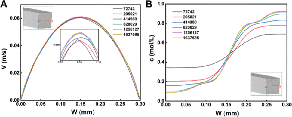
Meshing was the first step in numerical simulation. The higher the mesh quality, the finer the mesh elements and the closer the simulation results were to the real value. However, this was accompanied by time-consuming and labor-intensive calculations that placed a higher workload on the computer, creating mesh independence tests. In this study, a mesh study was carried out for a hyperbolic H5 micromixer with channel width W = 0.3 mm and Re = 10. A tetrahedral structured mesh of 72![[thin space (1/6-em)]](https://www.rsc.org/images/entities/char_2009.gif) 742, 205021, 414980, 820029, 1256127, and 1637585 was selected. The selected tetrahedral structured mesh used the same grid size for the other five curves. Fig. 2A shows the velocity distribution in the centerline of the micromixer at the outlet cross-section. The results of the numerical simulations with six meshes were consistent. The peak velocity of 0.15 mm was scaled up and found to be saturated for simulations with mesh numbers 820029, 1256127, and 1637587. The results were consistent with the concentration distribution in Fig. 2B.
742, 205021, 414980, 820029, 1256127, and 1637585 was selected. The selected tetrahedral structured mesh used the same grid size for the other five curves. Fig. 2A shows the velocity distribution in the centerline of the micromixer at the outlet cross-section. The results of the numerical simulations with six meshes were consistent. The peak velocity of 0.15 mm was scaled up and found to be saturated for simulations with mesh numbers 820029, 1256127, and 1637587. The results were consistent with the concentration distribution in Fig. 2B.
 |
| | Fig. 2 Distribution of velocity (A) and concentration (B) at the centerline of the outlet (Re = 10). | |
Taking the 1637587 mesh as the reference, we obtained the velocity errors as well as the calculation time at 0.15 mm and concentration at 0.05 mm for the first five grids, as shown in Table S1 (ESI†). In terms of time consumption, the computation time of the 1256127 mesh was more than three times that of the 820029 mesh, so the 820029 grid was chosen for the numerical simulation of the hyperbolic micromixer model.
3 Results and discussion
3.1 Effects of channel width, pressure drop and Re on micromixers with different curvatures
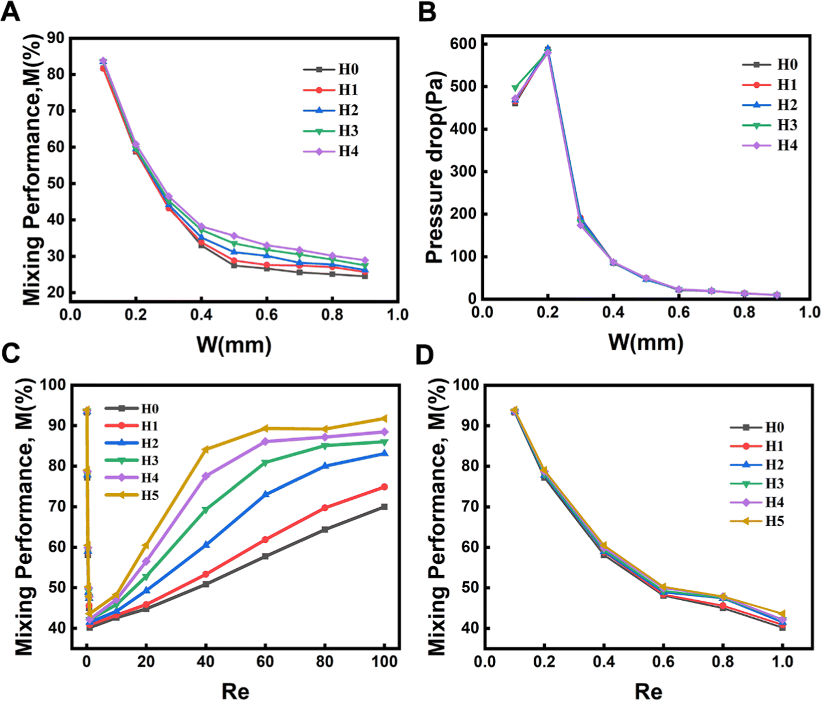
To investigate the effect of the width of the channels on the mixing efficiency of micromixers, five hyperbolic curves (H0, H1, H2, H3, and H4) were used for simulation research studies (Fig. 1). The mixing efficiency of the five micromixers (H0 to H4) decreased with increasing the channel widths ranging from 0.1 to 0.9 mm (Re = 10) (Fig. 3A). The larger the diameter of the hyperbolic channel, the lower the flow velocity when the Re is the same according to the eqn (6). Controlling pressure drop was an important step while considering the integration of micromixers into microfluidic systems. As shown in Fig. 3B, the pressure drops first increased and then decreased with increasing the channel width, and the amplitude change in the pressure drop was largest when the width was 0.3 mm. Then the pressure drop decreased continuously as the width continued to increase. Considering the influence of the channel width and the pressure drop on the mixing efficiency of the micromixer and the optimal effect of the three-dimensional (3D) fabrication and experiments of the microfluidic chips, a micromixer with a channel width of 0.3 mm was selected. Then, after selecting the channel width, six kinds of hyperbolic micromixers with different curvatures were simulated to reveal the relationship between curvatures and mixing efficiency, as seen in Fig. 3C and D.
 |
| | Fig. 3 Influencing factors of mixing performance. Effect of channel width on the mixing efficiency (A) and pressure drop (B). Mixing efficiency comparison of six hyperbolic curves in Re from 0.1 to 100 (C) and 0.1 to 1.0 (D). | |
When Re ranged from 0.1 to 1, the mixing efficiency decreased sharply, and the lowest was when Re = 1. The main reason was that molecular diffusion dominated the mixing strength at this stage. The lower the Re, the lower the flow rate. The longer the fluid diffused in the microchannel, the more thorough the molecular diffusion and the higher the mixing efficiency. With the increasing of Re, the convective diffusion gradually intensifies, and then the channel structure plays an important role. The micromixer's hybrid efficiency M increased rapidly. The mixing efficiency of hyperbolic H5 was the highest within a range of 1–100 under the conditions of the same Re.
3.2 Effect of molecular diffusion and chaotic advection
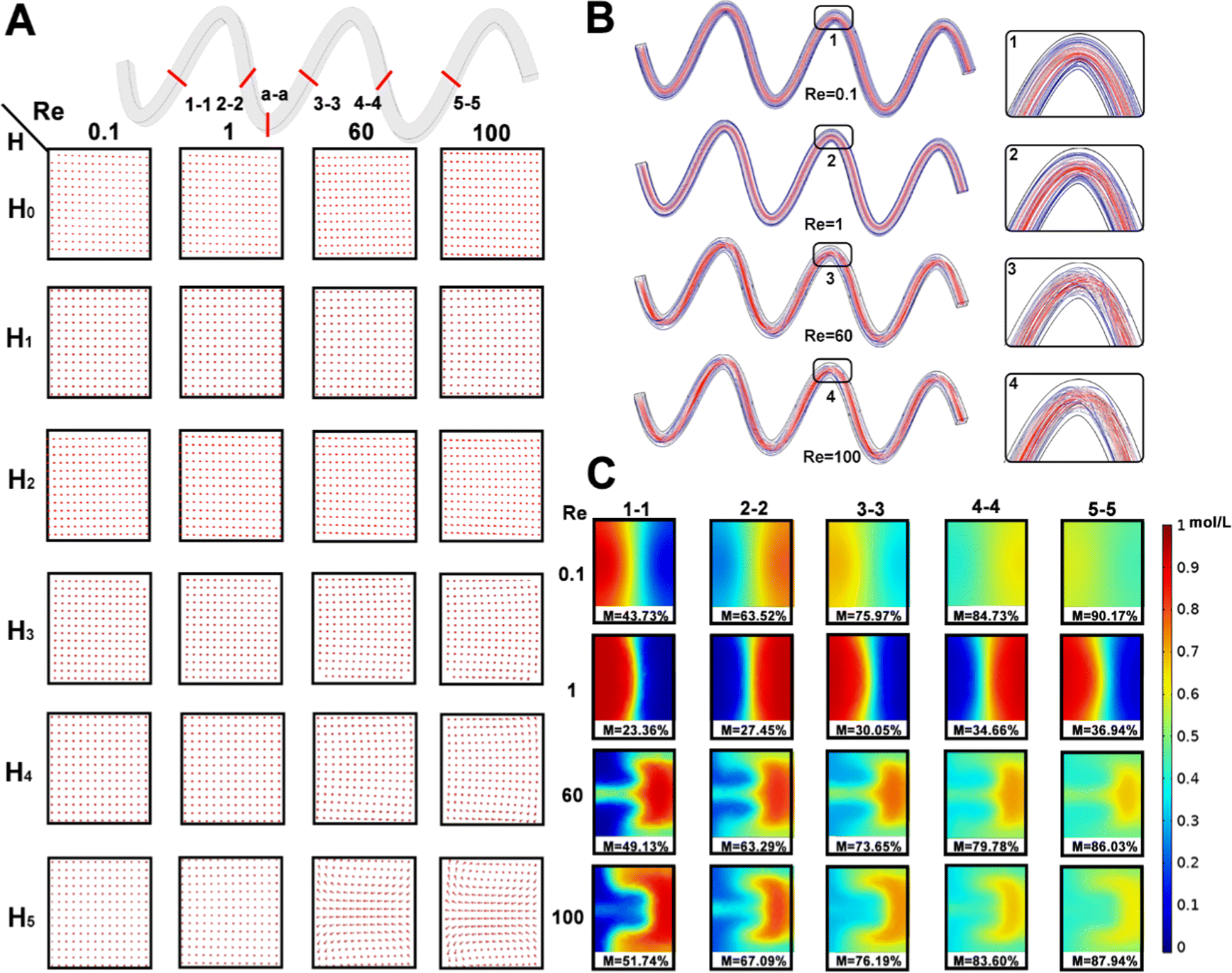
It was necessary to research the effect of molecular diffusion and chaotic advection. Firstly, the flow velocity direction of the cross section (a-a) of the six micromixers was studied under the different Re (0.1, 1.0, 60, and 100). As shown in Fig. 4A, all six hyperbolic curves were parallel to the channel in a single flow direction at the cross section (a-a), indicating that the solution mixing efficiency M was mainly determined through molecular diffusion. With increasing the Re, the flow velocity in the x-axis and y-axis directions gradually appeared in the horizontal plane of the micromixer's cross-section. This phenomenon was not visible for H0 to H3 micromixers. However, the Dean vortex gradually became more visible in H4 and H5 micromixers as the hyperbolic curvature became smaller.
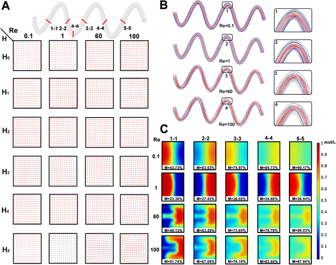 |
| | Fig. 4 (A) Flow direction of six hyperbolic curves of the micromixer at different Re for the cross-sections. (B) Streamlining of the hyperbolic micromixer's curve H5 micromixer at different Re and amplified view at channel and curves. (C) Concentration distribution of the cross-section of the hyperbolic curve H5 of the micromixer at different Re. | |
Meanwhile, when the slope of the asymptote deviated to infinity, the slope was close to the perpendicular y-axis according to the hyperbolic asymptotic eqn (10), and then the Dn tended to 0. When the slope of the asymptote deviated to 0, the slope was close to the parallel x-axis, and the Dn tended to infinity. Therefore, these results were explained by the Dn. The smaller the eccentricity of the hyperbola, the higher the mixing efficiency, i.e., the greater the degree of curvature of the hyperbola, the higher the mixing efficiency under the same conditions.
Then, the hyperbolic H5 micromixer was selected to research the mixing efficiency mechanism of the hyperbolic micromixer. The flow lines in the microchannel at different Re and local expansion of the corresponding curves is studied in Fig. 4B. In detail, the flow lines were parallel throughout and would not interfere with each other at Re = 0.1–1. The streamlines were no longer parallel in the curve and intersected longitudinally when Re values were 60, and 100, respectively. Therefore, the mixing efficiency of the micromixer increased significantly with the increase of the vortex intensity when the Re was in 1–100, and this phenomenon is consistent with Fig. 3C. As illustrated in Fig. 4C, the concentration distribution of the micromixer under different cross sections (1-1, 2-2, 3-3, 4-4, 5-5) was studied at different Re values.
The two fluid concentrations showed a “butterfly shape” and the liquid on both sides of the wall did not contact at low Re. Hence, the mixing slowly moved from the cross-section's centerline to the molecular diffusion's sides. The lower the flow rate, the longer the mixing time, and the more visible the mixing efficiency. So, the mixing efficiencies of the five cross-sections at Re = 0.1 were greater than Re = 1. Interestingly, chaotic advection gradually dominated the mixing process with increasing the Re. The cross section of the two solutions produced Dean vortices in the case of Re = 60 and 100, the liquid distribution became disordered, the mixing speed was accelerated, and then the mixing efficiency improved significantly.
3.3 Design of the hyperbolic microfluidic detection chip
To perform reagent mixing, hyperbolic curves H5 with three portions were inserted in the detector chip to create an efficient mixing effect (Fig. S1, ESI†). Then, the mixing efficiency of H5 curves could reach as high as 97.97% (Re = 20). Then, the hyperbolic curve H5 with three portions were inserted the developed DHMC to create an efficient mixing effect (Fig. 5). As illustrated in Fig. 5A, the DHMC included the channel layer, the reaction layer, and the basal layer. In the channel layer, the four reservoirs can storage the different reaction samples. The hyperbolic microchannel can achieve the full mixing of different reagents to enable sensitive detection and the square microchannel can be a reaction section. Notably, each reservoir had an independent microchannel flow that led to a rotary valve. The reaction layer with a three-channel chip was established for capturing the target. The assembled DHMC can connect the corresponding reservoir to the branch channel, and adjust the reagent flow and direction through the rotary valve (Fig. 5B). In addition, the chip mold, holder, and rotary valve were all printed using an AccuFab-L4 K light-curing 3D printer (Fig. S2, ESI†), which provided convenient conditions for mass production of chips. The as-prepared DHMC had the characteristics of high integration and automation.
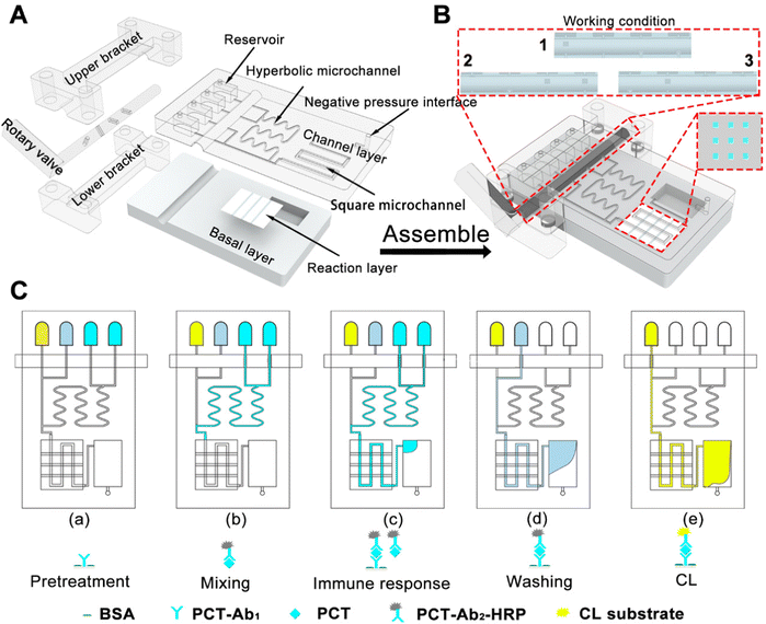 |
| | Fig. 5 (A) Components of the hyperbolic microfluidic detection chip. (B) The assembly and the operating state of the rotary valve. (C) Schematic diagram of detection of PCT based on the developed DHMC. | |
Then, the DHMC was executed to analyze PCT (Fig. 5C). The four reservoirs from right to left included PCT, PCT-Ab2-HRP, PBS wash containing 0.5% Tween (PBST) and a chemiluminescent substrate. The middle layer (reaction layer), a silica-gel membrane, encapsulated the capture antibody PCT-Ab1 and 5% BSA solution (Fig. S3, ESI†).40 The different reagents were injected and controlled using a rotary valve to achieve PCT detection according to (a) to (e) in Fig. 5C, and the specific process is explained in detail in the ESI.† After the immunoreaction reaction, the chemiluminescence (CL) intensity can achieve the highly sensitive determination of PCT.41
3.4 Detection of PCT by DHMC
The developed DHMC can enable detection of PCT based on the change of CL intensity and the image of CL intensity also can be obtained utilizing the CLD apparatus (Fig. 6A). Interestingly, the signal of CL intensity can be monitored in 5 min, and CL intensity were gradually enhanced as time (5–20 min) and Re (1, 10, and 20) increased, which provided an important direction in the rapid detection of PCT (Fig. 6B). In detail, the results in Fig. 6C used a GEL-PRO Analyzer to convert the optical signals to digital ones.
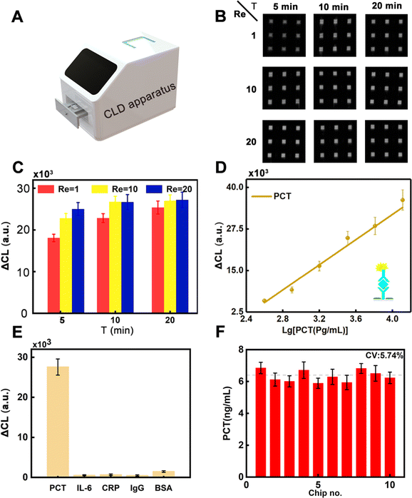 |
| | Fig. 6 (A) Chemiluminescence detection apparatus, PCT concentration of 3.2 ng mL−1 at different Re and incubation times for dot signal (B) and corresponding ΔCL intensity (C). (D) Standard curve between the PCT concentration and ΔCL intensity (N = 3). (E) The selectivity assay of the developed for detection of PCT. (F) The stability research of the chips (No. 10) for PCT (6.4 ng mL−1) analysis. | |
For each interval, the ΔCL was calculated using the following eqn (11):
| | | ΔCL = CLsample − CLblank | (11) |
where CL
sample and CL
blank are the average CL intensity of the triplicates of the sample and blank groups (the [PCT] = 0), respectively.
When Re = 1, the ΔCL intensity varied with the incubation time, with the lowest intensity at 5 min of incubation time. The result reflected that in addition to Re, incubation time also affected the intensity of ΔCL. When Re = 10, the ΔCL intensity at 5 min was higher than that under the same condition with Re = 1, but it was not as high as that at 10 min and 20 min, and the intensity tended to be stable at these two times. When Re = 20, the intensity of ΔCL was essentially the same for all three times. Therefore, Re = 10 and incubation time of 10 min was finally set as the optimal experimental conditions for the microfluidic chip to achieve rapid and highly sensitive detection of PCT. With increasing the concentration of PCT from 0 to 12.8 ng mL−1, the ΔCL intensity was gradually enhanced due to the capturing ability of antibody for PCT, which can improve the sensitivity for the determination of the target. The ΔCL intensity showed a good linear relationship with PCT, ranging from 0.4 ng mL−1 to 12.8 ng mL−1 (Fig. 6D) with a limit of detection (LOD) as low as 0.17 ng mL−1, which had a high detection sensitivity compared with that previously reported (Table S2, ESI†), implying that the developed strategy has a high potential in POCT for clinical diagnostic needs. Thus, the developed DHMC can enable detection of PCT with specificity (Fig. 6E). From the experimental results, it was observed that the chip had a good response to the target (3.2 ng mL−1), while it did not have any response to the other proteins, even if they had high concentrations (10 ng mL−1). The stability of the chip was critical for PCT in clinical diagnosis. As shown in Fig. 6F, the constructed DHMC had good stability and reproducibility for the detection of PCT (CV 5.74%). Meanwhile, to confirm the practicality of our approach, we compared our DHMC with ELISA Kit in detecting PCT in 12 serum samples (Fig. S4, ESI†). Both the DHMC and ELISA Kit can accurately determine the negative samples and positive samples. Then, the quantitative results of this DHMC for detection of PCT in serum samples agreed well with those of the ELISA Kit with a correlation coefficient of 0.968, implying that the developed chips can potentially be employed for the determination of PCT in POCT.
4 Conclusions
In summary, this study started with theory and used numerical simulations to analyze the effects of Re, the radius of curvature R, and the microchannel width on the mixing efficiency of a hyperbolic micromixer, resulting in a novel form of a hyperbolic passive high-efficiency mixer. The effects of molecular diffusion and convective diffusion on the mixing efficiency were analyzed by the flow direction, streamline, and concentration distribution in the microchannel. The mixing efficiency of the micromixer was verified mathematically based on the relationship between Dn and Re and the radius of curvature R. The hyperbolic micromixer was embedded with optimal conditions into the microfluidic detection chip to form a DHMC, which can quickly detect PCT with sensitivity, showing great potential in POCT with a good readout.
Author contributions
Binfeng Yin: conceptualization, methodology, writing – original draft, writing – review & editing, funding acquisition. Wenkai Yue: methodology, investigation, writing – original draft, formal analysis. A S M Muhtasim Fuad Sohan: investigation. Teng Zhou: funding acquisition, investigation. Xinhua Wan, Liuyong Shi and Changcheng Qian: validation, software, formal analysis. Xiaodong Lin: writing – review & editing, supervision, funding acquisition.
Conflicts of interest
There are no conflicts to declare.
Acknowledgements
This work was funded by the National Natural Science Foundation of China (No. 52075138 and No. 61964006), the Natural Science Foundation of Jiangsu Province (No. BK20190872), the Natural Science Foundation of the Jiangsu Higher Education Institutions of China (No. 22KJB150050), the Jiangsu Agricultural Science and Technology Innovation Fund (No. CX(21)3162), the Market Supervision Administration Science and Technology Fund of Jiangsu Province (No. KJ2023076), the Postgraduate Research & Practice Innovation Program of Jiangsu Province (No. KYCX22_3479), the Hainan Province Science and Technology Special Fund (No. ZDYF2022SHFZ301 and ZDYF2022SHFZ033), and the Yangzhou City Science and Technology Special Fund (YZ2022180). The authors thank Yangzhou YIXIN 3D Tech Co., Ltd for providing technical support on 3D printing.
References
- J. H. Zheng, T. Cole, Y. X. Zhang, J. Kim and S. Y. Tang, Biosens. Bioelectron., 2021, 194, 113666 CrossRef CAS PubMed.
- H. Evard, H. Priks, I. Saar, H. Aavola, T. Tamm and I. Leito, Micromachines, 2021, 12, 671 CrossRef PubMed.
- Y. Bai, M. Gao, L. L. Wen, C. Y. He, Y. Chen, C. L. Liu, X. F. Fu and S. Q. Huang, Biotechnol. J., 2018, 13, 1700170 CrossRef PubMed.
- G. P. Chen, J. Mater. Chem. B, 2021, 9, 3606–3607 RSC.
- Y. Zhang, A. W. Zhou, S. L. Chen, G. Z. Lum and X. S. Zhang, Biomicrofluidics, 2022, 16, 011301 CrossRef CAS.
- X. W. Fu, Z. H. Yao and X. W. Zhang, Microfluid. Nanofluid., 2016, 20, 106 CrossRef.
- K. W. Oh, K. Lee, B. Ahn and E. P. Furlani, Lab Chip, 2012, 12, 515–545 RSC.
- C. Y. Lee, W. T. Wang, C. C. Liu and L. M. Fu, Chem. Eng. J., 2016, 288, 146–160 CrossRef CAS.
- M. Thiele, A. Knauer, D. Malsch, A. Csaki, T. Henkel, J. M. Kohler and W. Fritzsche, Lab Chip, 2017, 17, 1487–1495 RSC.
- K. S. Elvira, X. C. I. Solvas, R. C. R. Wootton and A. J. deMello, Nat. Chem., 2013, 5, 905–915 CrossRef CAS PubMed.
- C. Y. Lee and L. M. Fu, Sens. Actuators, B, 2018, 259, 677–702 CrossRef CAS.
- G. Z. Cai, L. Xue, H. L. Zhang and J. H. Lin, Micromachines, 2017, 8, 274 CrossRef.
- R. Hu, C. Liu, J. Xuan, Y. Z. Xu, T. Li, B. F. Liu, Y. Li and Y. H. Yang, Sens. Actuators, B, 2019, 293, 312–320 CrossRef CAS.
- G. Yesiloz, M. S. Boybay and C. L. Ren, Anal. Chem., 2017, 89, 1978–1984 CrossRef CAS PubMed.
- P. Modarres and M. Tabrizian, Microsyst. Nanoeng., 2020, 6, 60 CrossRef PubMed.
- S. Yu, T. J. Jeon and S. M. Kim, Chem. Eng. J., 2012, 197, 289–294 CrossRef CAS.
- A. Dehghan, A. Gholizadeh, M. Navidbakhsh, H. Sadeghi and E. Pishbin, Sens. Actuators, B, 2022, 351, 130919 CrossRef CAS.
- A. R. Rezk, A. Qi, J. R. Friend, W. H. Li and L. Y. Yeo, Lab Chip, 2012, 12, 773–779 RSC.
- M. B. Okuducu and M. M. Aral, Micromachines, 2021, 12, 372 CrossRef PubMed.
- X. Y. Chen and T. C. Li, Chem. Eng. J., 2017, 313, 1406–1414 CrossRef CAS.
- P. R. Mashaei, S. Asiaei and S. M. Hosseinalipour, Chem. Eng. Process., 2020, 154, 108006 CrossRef CAS.
- A. Alam and K. Y. Kim, Chem. Eng. J., 2012, 181, 708–716 CrossRef.
- V. S. Duryodhan, R. Chatterjee, S. G. Singh and A. Agrawal, Exp. Therm. Fluid Sci., 2017, 89, 119–127 CrossRef CAS.
- I. Shah, S. W. Kim, K. Kim, Y. H. Doh and K. H. Choi, Chem. Eng. J., 2019, 358, 691–706 CrossRef CAS.
- V. E. Ahmadi, I. Butun, R. Altay, S. R. Bazaz, H. Alijani, S. Celik, M. E. Warkiani and A. Kosar, Chem. Eng. Res. Des., 2021, 168, 490–498 CrossRef CAS.
- N. Nivedita, P. Ligrani and I. Papautsky, Sci. Rep., 2017, 7, 44072 CrossRef PubMed.
- N. Xiang, Q. Li, Z. G. Shi, C. G. Zhou, F. T. Jiang, Y. Han and Z. H. Ni, Electrophoresis, 2020, 41, 875–882 CrossRef CAS.
- N. Xiang and Z. H. Ni, Talanta, 2021, 235, 122807 CrossRef CAS PubMed.
- N. Xiang, S. L. Wang and Z. H. Ni, Electrophoresis, 2021, 42, 2256–2263 CrossRef CAS PubMed.
- X. Y. Chen, T. C. Li, H. Zeng, Z. L. Hu and B. D. Fu, Int. J. Heat Mass Transfer, 2016, 98, 131–140 CrossRef CAS.
- V. Khaydarov, E. S. Borovinskaya and W. Reschetilowski, Appl. Sci., 2018, 8, 2458 CrossRef CAS.
- R. J. Wang, B. Q. Lijin, D. D. Shi and Z. F. Zhu, Sens. Actuators, B, 2017, 249, 395–404 CrossRef CAS.
- H. Lee, M. T. Oh, Y. J. Lee, K. H. Son, N. Choi, B. C. Lee and S. H. Lee, Sens. Actuators, B, 2020, 319, 128317 CrossRef CAS.
- H. W. Chu, C. H. Liu, J. S. Liu, J. Yang, Y. C. Li and X. J. Zhang, Sens. Actuators, B, 2021, 348, 130708 CrossRef CAS PubMed.
- P. Mehrdel, S. Karimi, J. Farre-Llados and J. Casals-Terre, Micromachines, 2018, 9, 552 CrossRef PubMed.
- N. Singh, P. Rai, M. A. Ali, R. Kumar, A. Sharma, B. D. Malhotra and R. John, J. Mater. Chem. B, 2019, 7, 3826–3839 RSC.
- M. S. Cheri, H. Latifi, M. S. Moghaddam and H. Shahraki, Chem. Eng. J., 2013, 234, 247–255 CrossRef.
- A. Usefian and M. Bayareh, Meccanica, 2020, 55, 1025–1035 CrossRef.
- B. F. Yin, W. K. Yue, A. Sohan, T. Zhou, C. C. Qian and X. H. Wan, ACS Omega, 2021, 6, 30779–30789 CrossRef CAS PubMed.
- B. F. Yin, X. H. Wan, M. Z. Yang, C. C. Qian and A. Sohan, Mil. Med. Res., 2022, 9, 8 CAS.
- B. F. Yin, C. C. Qian, X. H. Wan, A. Sohan and X. D. Lin, Biosens. Bioelectron., 2022, 212, 8 CrossRef.
|
| This journal is © The Royal Society of Chemistry 2023 |
Click here to see how this site uses Cookies. View our privacy policy here. 
 *a,
Wenkai
Yue
a,
A. S. M. Muhtasim Fuad
Sohan
*a,
Wenkai
Yue
a,
A. S. M. Muhtasim Fuad
Sohan