
On-site formation of silver decorated carbon as an anodeless electrode for high-energy density all-solid-state batteries†
Yun-Chae
Jung
 a,
Chihyun
Hwang
a,
Myung-Jun
Kwak
a,
Sang-Jin
Jeon
ab,
Yun Jung
Lee
b,
Won-Jin
Kwak
c,
Hyun-Seung
Kim
a,
KyungSu
Kim
a,
Woosuk
Cho
*a and
Ji-Sang
Yu
*a
a,
Chihyun
Hwang
a,
Myung-Jun
Kwak
a,
Sang-Jin
Jeon
ab,
Yun Jung
Lee
b,
Won-Jin
Kwak
c,
Hyun-Seung
Kim
a,
KyungSu
Kim
a,
Woosuk
Cho
*a and
Ji-Sang
Yu
*a
aAdvnaced Batteries Research Center, Korea Electronics Technology Institute, 25 Saenari-ro, Bundang-gu, Seongnam, Gyeonggi 13509, Republic of Korea. E-mail: cho4153@keti.re.kr; jisang@keti.re.kr
bDepartment of Energy Engineering, Hanyang University, Seoul, 04763, Republic of Korea
cSchool of Energy and Chemical Engineering, Ulsan National Institute of Science and Technology (UNIST), Ulsan, 44919, Republic of Korea
First published on 10th October 2023
Abstract
All-solid-state batteries (ASSBs) are promising alternatives to lithium-ion batteries owing to their high energy density and safety. Recent studies on “anodeless” electrodes with Li-soluble metallic materials (e.g., silver nanoparticles) and carbon materials in ASSBs have shown improvements in the energy density of these cells. However, poor dispersion between metal nanoparticles and carbon materials in anodeless electrodes leads to disproportionate electrochemical phenomena. Moreover, the dendritic growth and uneven reactions caused by these imbalances impair the life cycle of ASSB cells. To address this issue, we introduce carbon-supported silver nanoparticle-based anodeless electrodes. Ag ion complexes were thermally reduced, and the reduced silver nanoparticles were well dispersed on the carbon surface. This electrode reduces overpotential during the lithiation process with less silver and provides high-rate performance. An ASSB cell using the anodeless electrode with carbon-supported silver nanoparticles exhibits 91% capacity retention after 500 cycles.
Introduction
All-solid-state batteries (ASSBs) using solid electrolytes have attracted increasing attention as next-generation batteries that meet higher energy density and safety requirements.1–6 Without flammable organic liquid electrolytes in the cell configuration, ASSBs are expected to provide improved energy density and safety compared to conventional lithium-ion batteries (LIBs). The ionic conductors used as solid electrolytes are typically oxides, sulfides, or polymer-based materials.7–9 Among the various solid electrolyte materials, sulfides are especially well-suited because of their high ionic conductivity, ductility, and deformability.10–14Representative sulfide solid electrolytes include Li6PS5X (argyrodite; X = Cl, Br, or I), Li2S–P2S5 (LPS), and Li10GeP2S12 (LGPS), among which the argyrodite electrolytes have been studied extensively because of their ease of synthesis, high ionic conductivity, and relatively better (electro-)chemical stability.
In the development of high-energy density batteries, Li metal is currently the most attractive anode material due to its high theoretical capacity (3860 mA h g−1) and low reduction potential (−3.04 V vs. the standard hydrogen electrode).15 However, despite recent advances in surface modulation and electrode structure engineering, batteries using Li metal anodes still suffer from poor reversibility and limited cycle life, primarily because of the uncontrollable Li deposition/dissolution process and considerable expansion in volume.16–20 ASSBs employing Li metal anodes with the same cell configuration as conventional LIBs, except for the use of solid electrolytes, also suffer from the uncontrollable electrochemical behavior of Li, which results in interfacial side reactions and contact loss between Li and the solid electrolyte during cycling.21–23 These problems are exacerbated when the battery is operated under a high current density or high areal capacity, owing to the low intrinsic diffusion coefficient (∼10–11 cm2 s−1) of Li, which is linked to the slow surface diffusion kinetics of Li and atoms at the interface. Therefore, further research is required to resolve these issues at the interface between the solid electrolyte and Li metal by stabilizing the interface or controlling the Li deposition/dissolution behavior on the anode side.
Recent studies have been conducted on the use of anodeless electrodes instead of Li metal in ASSBs.24–30 In anodeless applications, only the current collector serves as the anode. Li is absent in the anode in the initial stage, with the cathode serving as the sole source of Li metal during charging. However, simply removing Li metal from the anode side does not guarantee improved performance and stability, as the presence of Li deposits and growing Li dendrites cause uncompensated Li isolation (for example, the formation of “dead” lithium) and irreversible Li consumption, as well as inhomogeneous stress distribution at the interface between the Li metal and solid electrolyte during cycling, which can result in a sudden battery failure.31,32 This instability at the anodic interface can be effectively mitigated by introducing an additional intervening layer into the solid electrolyte/current collector interface, which prevents direct contact between the solid electrolyte and Li metal, alleviates mechanical stress at the interface, and allows adequate Li transfer, leading to the uniform and reversible deposition of Li metal.
Recent approaches for sulfide-based ASSBs have utilized nanocomposite interlayers composed of silver and carbon (Ag–C) nanoparticles as anodeless electrodes.24,26–28 The Ag–C interlayer enables a high-energy density and extended cycle life, resulting from the synergistic contribution of Ag and carbon: Ag serves as the Li-ion conductor by alloying with the Li metal and, owing to its huge capacity for solid solution with Li, lowers the nucleation energy, consequently facilitating compact and uniform Li deposits on the current collector, securing high reversibility, and providing a Li-ion diffusion pathway among Ag nanoparticles along its surface.33,34
In the early stages of charging, Li ions transported through the solid electrolyte are preferentially deposited as metallic Li on the Ag–C interlayer, rather than on the solid electrolyte, owing to favorable thermodynamics. The Ag–C nanocomposite interlayer is a mixed ionic–electronic conductor that guides Li deposits toward the negative electrode side via diffusional creep.35 The conduction kinetics of Li metal through the Ag–C interlayer are fast enough to relieve the local stress derived from Li deposits, preventing direct contact between Li and the solid electrolyte and Li dendrite penetration.
In this study, we demonstrated the use of a carbon-supported silver nanoparticle as an anodeless electrode. The thermally reducible silver ion complex forms nanoparticles several nanometers in size on the surface of the carbon material during the electrode fabrication process. The silver nanoparticles and carbon material in the anodeless electrode are uniformly dispersed. Compared to simply mixing silver nanoparticles and carbon materials, the carbon-supported silver nanoparticle-based anodeless electrode showed improved overpotentials in the lithiation and plating processes during the charging steps. In the galvanostatic cycling test, the critical current density of the anodeless electrode increased, and its potential for high-rate performance was confirmed. A pouch-type ASSB with carbon-supported silver nanoparticles was fabricated and its cell performance was evaluated at a low external pressure (4 MPa). 300 mAh-class pouch-type full cells exhibited excellent specific capacity and cycle life.
Results and discussion
Carbon-supported silver nanoparticles were synthesized in a single step. The electrode slurry containing Ag ion complexes (denoted as Ag-IC) was homogeneously blended with carbon black and exhibited stability at room temperature. The slurry was coated onto the current collector and dried at 100 °C to form an anodeless electrode (Fig. 1). When the ion complexes are exposed to higher temperatures, they become reactive. The FTIR spectra of Ag-IC prepared at distinct temperatures (dried at 40 °C and 100 °C) showed the disappearance of the O–H stretching at 3000–3500 cm−1 and the appearance of the characteristic C–N stretching at 1610 cm−1 (Fig. S1†), implying that the Ag ion complex was thermally reduced on the surface of carbon black at 100 °C. This allows the silver ions to be rapidly reduced, resulting in metal nanoparticles that have sufficient surface stabilization to prevent significant agglomeration. Specifically, when combined with the electrode preparation procedure, our strategy utilizing the silver ion complex takes advantage of the following benefits: (i) process solvent (i.e., NMP) compatible solubility of the silver ion complex, and (ii) low decomposition temperature (∼100 °C) for a simultaneous dry process and silver nanoparticle creation. In this regard, with the use of the silver ion complex in the electrode fabrication process, silver decorated carbon electrodes could be practically prepared in a reproducible manner by means of a single step, which is a significant advance over the previously reported strategy that separates the synthesis of the electrode material (i.e., Ag NP decorated carbon) and the electrode fabrication processes.26,36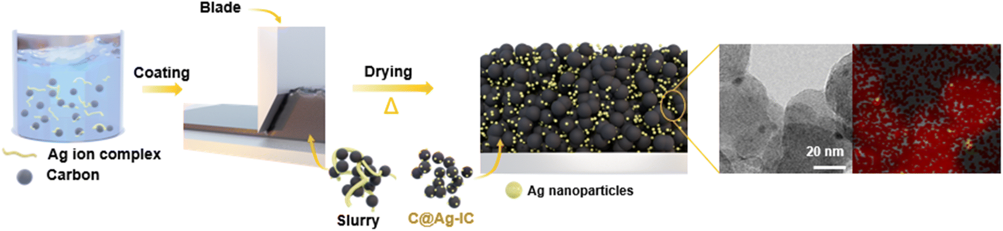 | ||
| Fig. 1 Schematic illustration of the C@Ag-IC electrode fabrication process. | ||
The carbon-supported silver nanoparticle (denoted as C@Ag-IC) electrodes were characterized by their Ag content. For comparison, a mixture of silver nanoparticles and carbon black (denoted as C/Ag) was prepared using a physical mixing process. Powder X-ray diffraction (PXRD) of C@Ag-IC and C/Ag (Fig. 2a and S2†) revealed characteristic diffraction peaks for metallic Ag in the absence of any oxidized surface. The presence of metallic silver in C@Ag-IC was consistent with the elemental state and surface chemical composition determined by X-ray photoelectron spectroscopy (XPS) (Fig. 2b). The strong peaks located at 374.1 eV and 368.10 eV are due to Ag 3d3/2 and Ag 3d5/2, respectively, which indicates that they consist of pure Ag. In the C 1s spectra, C@Ag-IC featured an increased Csp2/Csp3 ratio compared to that with carbon black, indicating that the defective edge sites for carbon black provided additional nucleation/reduction sites for anchoring Ag nanoparticles, mainly because of their high surface reactivity, and these sites decreased during the in situ reduction process of Ag-IC. This reduction in the number of defects on the carbon black surface was also confirmed by Raman spectroscopy (Fig. 2c). The D-to-G intensity ratio (ID/IG), attributed to the presence of defective sites on the carbon black, decreased with an increasing amount of Ag-IC, indicating that Ag nanoparticles were primarily attached to the defect sites of carbon black during the reduction process, where the defect sites are selectively healed by Ag nanoparticles.
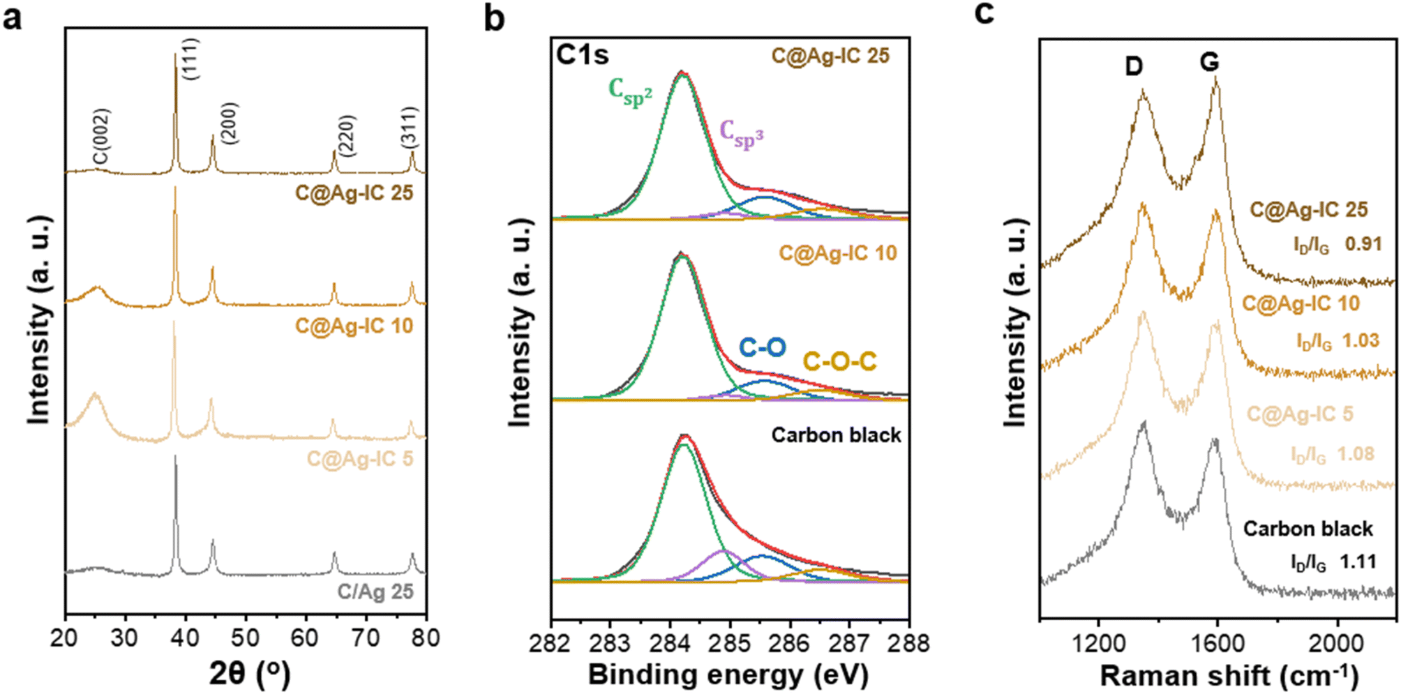 | ||
| Fig. 2 (a) PXRD patterns of C/Ag 25 and C@Ag-ICs anodeless electrodes. (b) XPS C 1s spectra of carbon black and C@Ag-ICs. (c) Raman spectra of carbon black and C@Ag-ICs. | ||
Transmission electron microscopy (TEM) was used to study the morphology and distribution of carbon black, silver nanopowder, and carbon-supported silver nanoparticles in the anodeless electrodes (Fig. 3a and S3†). The carbon, silver composites were sampled from the fabricated anodeless electrodes. Carbon black and silver nanoparticles both had sizes of approximately 50 nm. In contrast, the silver nanoparticles in C@Ag-ICs had a particle size of approximately 10 nm. As the particle size decreased, the surface area increased at the same content. Thus, the surface area that can react with lithium in the electrode is significantly increased for the carbon-supported Ag nanoparticles. However, at concentrations of up to 25 wt% Ag, some of the silver grew unevenly to a somewhat larger size, and some parts of dispersion were worse than that when simply mixing powder. The uneven growth is potentially due to the excessive concentration of Ag precursors.
The cross-sectional images of the anodeless electrodes were obtained using scanning electron microscopy (SEM) with energy-dispersive spectroscopy (EDS) (Fig. 3b and S4†). When powders are simply mixed, the agglomeration of some components is expected to adversely affect battery characteristics, such as non-uniform currents. The SEM images of the samples prepared through the reduction process confirmed that the silver within the anode was well dispersed. When powders are simply mixed, the aggregation of some Ag particles is observed; however, in the ICs, such irregularities are almost absent, resulting in a considerably more uniform electrode plate; EDS analysis confirmed that Ag was evenly distributed within the anodeless electrode. Although they were prepared at a similar loading level (∼1 mg cm−2), the difference in the thickness of the anodeless electrodes was due to differences in the content and density of silver and carbon, as well as differences in the form of Ag bound to the carbon material.
The depth profile distribution of the silver nanoparticles within the anodeless electrodes was investigated and visualized using time-of-flight secondary ion mass spectroscopy (TOF-SIMS) with a 100 μm × 100 μm field of view (Fig. 3c). The local agglomeration of Ag nanoparticles within the C/Ag 25 electrode differed significantly from that of the C@Ag-IC 10 electrode; the relative amount of silver sharply increased in both the surface (from 0 to 70 s etching time) and bulk (from 200 to 2000 s etching time) regions for the C/Ag 25 electrode, implying that the C@Ag-IC 10 electrode exhibited more evenly distributed silver nanoparticles. 3D reconstructed distribution maps further indicated that silver nanoparticles within C/Ag electrodes were particularly concentrated at the bottom of the electrode compared to that in the C@Ag-IC electrodes (Fig. 3d). This indicates that the dispersion between the silver nanoparticles and other materials in the slurry was weak; thus, material migration occurred during the drying process after being coated onto the current collector. In contrast, Ag ion complexes are dissolved in a slurry solvent and are completely dispersed with the other materials, resulting in high dispersibility between the materials of the anodeless electrode. The excellent dispersibility indicates the potential to fabricate an anodeless electrode with equivalent performance using a reduced quantity of silver.
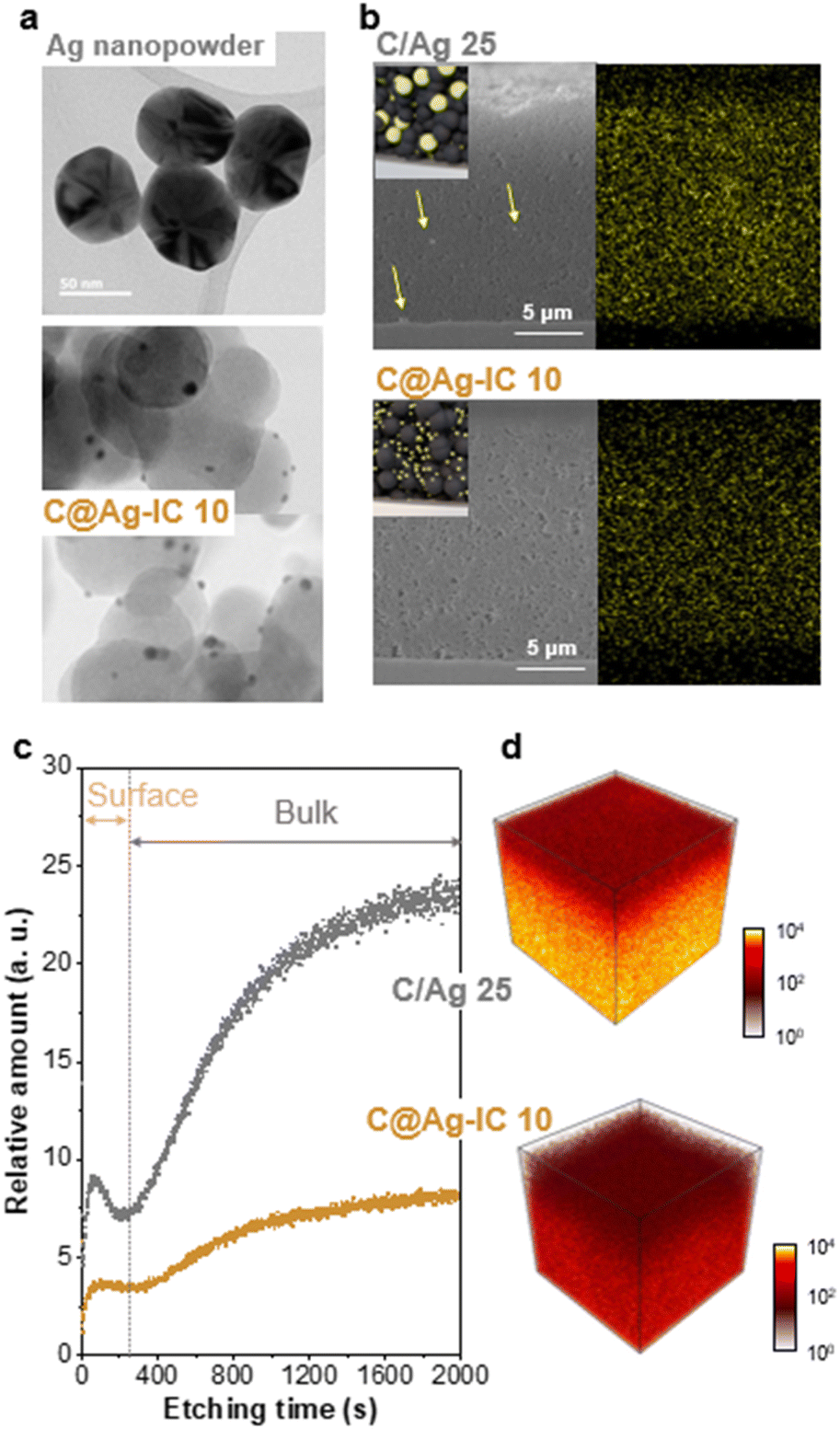 | ||
| Fig. 3 (a) TEM images of Ag nanopowder and Ag nanoparticles in C@Ag-IC 25 electrodes. (b) SEM images and SEM-EDS mapping images of C/Ag 10 and C@Ag-IC 25 electrodes: yellow represents Ag. (c) Depth profile and (d) 3D reconstructed mapping images of Ag nanoparticles in C/Ag 10 and C@Ag-IC 25 electrodes using TOF-SIMS. | ||
The electrodes were fabricated with various contents of Ag ion complexes to verify the variation in electrode formation (Fig. 4). We subsequently examined the size, distribution, crystallinity, and surface chemistry of the Ag NPs within C@Ag-ICs. TEM images highlighted the variations in the size and dispersion of Ag NPs on carbon black, which were produced through on-site reduction during the electrode fabrication process. By adjusting the quantity of silver ion complexes, meticulous control over the size and polydispersity of Ag NPs was attained. Fig. 4a–d show the TEM images and Fig. 4e–h show the corresponding size distribution histograms. As depicted in Fig. 4a–d, the size of Ag NPs increased as the amount of silver ion complexes increased; for instance, Ag NPs grew from 1.39 nm to 6.24 nm from IC 1 to IC 25 (see insets in Fig. 4e–h). This agglomeration can be because the increased density of Ag nuclei on carbon black shortens the diffusion pathway along the surface of carbon black, thereby inducing a favorable agglomeration of Ag nuclei to decrease the surface energy of Ag NPs.37 According to ICP measurements, the Ag and C contents in the anodeless electrodes were almost the same as the designed quantities (Table S1†). In the PXRD (Powder X-ray diffraction) results, a diffraction peak related to Ag was observed (Fig. 4i). However, other than a diminishing peak with an increased Ag precursor content, no notable changes were evident.
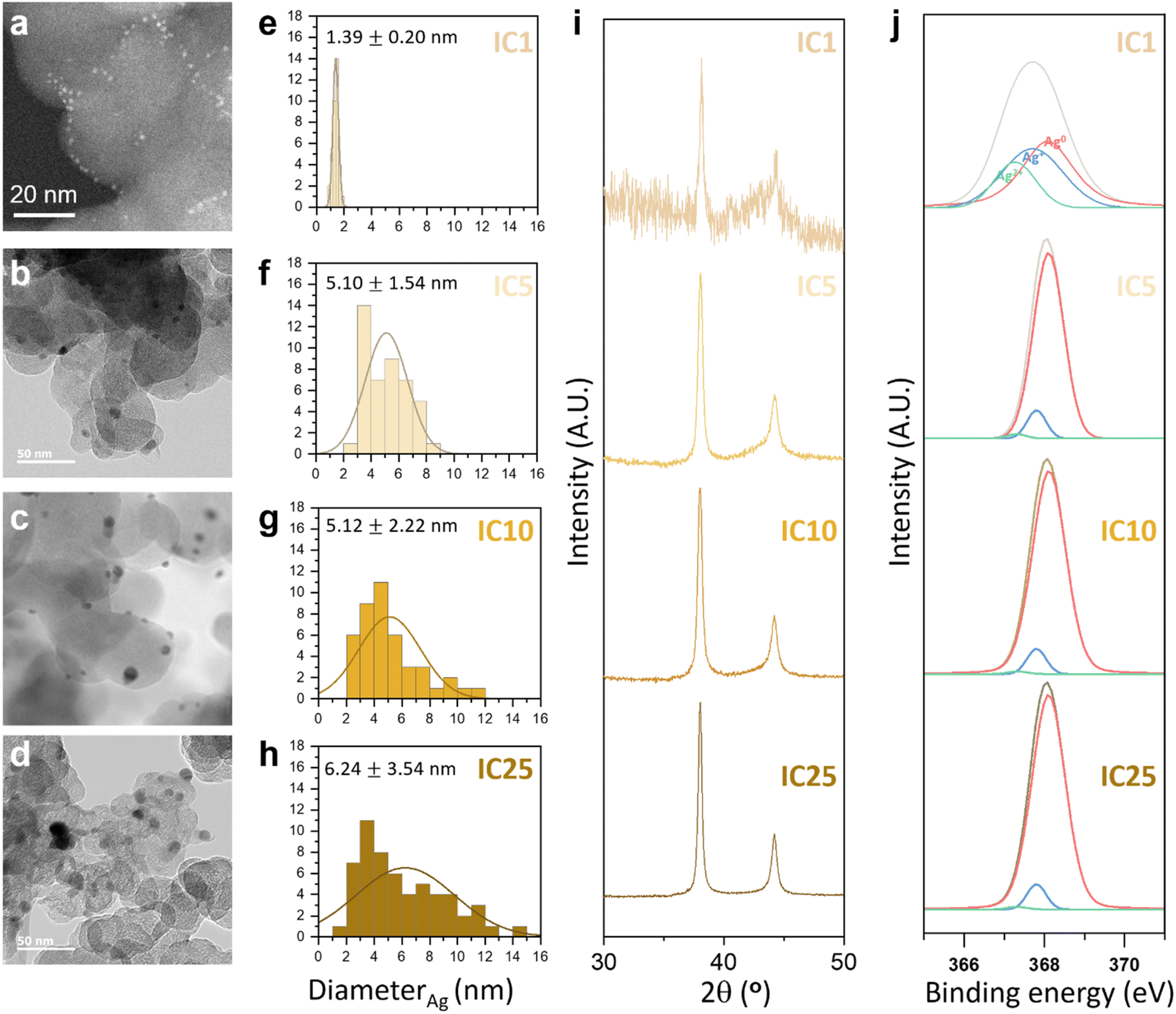 | ||
| Fig. 4 TEM images of C@Ag-IC electrodes with different Ag contents: (a) 1 wt%, (b) 5 wt%, (c) 10 wt% and (d) 25 wt%. Particle size distribution of Ag nanoparticles in C@Ag-IC electrodes: (e) 1 wt%, (f) 5 wt%, (g) 10 wt% and (h) 25 wt%. (i) PXRD patterns and (j) XPS Ag 3d spectra of C@Ag-IC electrodes. | ||
Further confirmation of the chemical composition of Ag NPs was derived from the Ag 3d and O 1s binding energy readings taken with X-ray photoelectron spectroscopy (XPS), as presented in Fig. 4j and S5.† The presence of metallic silver in C@Ag-ICs was indicated by the distinctive binding energies of Ag 3d3/2 and Ag 3d5/2, positioned at 374.1 eV and 368.10 eV respectively. However, C@Ag-ICs formulated with 1 weight percent ion complex demonstrated a slight yet discernible shift of roughly 0.5 eV to lower binding energies for the Ag 3d peak. This suggests that AgxO predominated in the surface layer of silver nanoparticles. The integrated area from the deconvoluted peaks corresponding to silver ions (Ag+ or Ag2+), indicative of the thickness (or quantity) of the AgxO layer, markedly decreased for C@Ag-IC5, 10, and 25. This can be attributed to their larger silver particle size, which in turn reduces surface energy, thus preventing further surface oxidation. While the presence of an oxide layer on the surface of silver nanoparticles is an inherent characteristic of all C@Ag-IC electrodes, the electrochemical reaction of the C@Ag-IC1 electrode, different from the other electrode (e.g., C@Ag-IC 5, 10, and 25), is significantly impaired due to the substantial amount of oxide layer present (56.13% AgxO; Table S2†). This is attributed to the thicker insulating oxide layer, which hinders the uniform alloying reaction of lithium with silver. With the identification of an unstable electrochemical reaction in the cell employing the C@Ag-IC 1 electrode during a preliminary test, we decided to exclude the C@Ag-IC 1 electrode from the subsequent electrochemical investigations.
Half-cells assembled with a solid electrolyte pellet, Li metal, and an anodeless electrode in a pressurized cell were prepared, and their initial cycling behaviors were evaluated. Both the anodeless electrode with silver nanoparticles and C@Ag-IC exhibited stable Li deposition/alloying during the discharge (Fig. 5a). The nucleation overpotentials of mixed anodeless electrodes were 19.6 mV (C/Ag 25), 20.3 mV (C/Ag 10), and 22.2 mV (C/Ag 5) during the first lithiation (Fig. 5b and S6†). For C@Ag-IC electrodes, the overpotentials were 15.5 mV (C@Ag-IC 25), 15.9 mV (C@Ag-IC 10), and 18.5 mV (C@Ag-IC 5). The reduced nucleation overpotentials of the C@Ag-IC electrodes improved the kinetics of the first deposition/alloying process, which is related to the improved dispersion of small Ag nanoparticles within the electrode, resulting in a more uniform electrochemical reaction within the cell. In the cases where the large silver nanoparticles in the C/Ag electrodes are unevenly distributed, the electrochemical reaction area is diminished and become concentrated in some areas, resulting in high nucleation overpotentials in the areas of higher resistance.
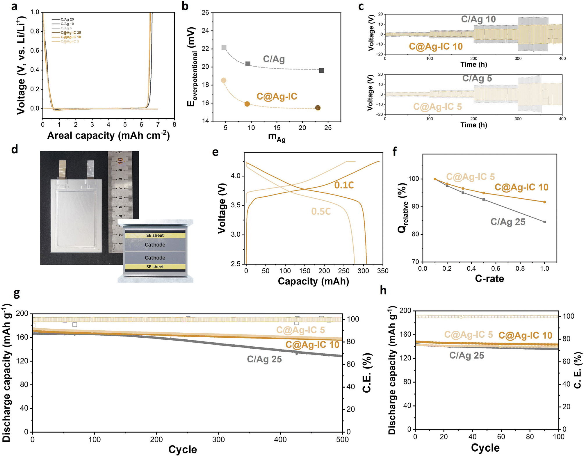 | ||
| Fig. 5 (a) Initial Li deposition and stripping voltage profiles of anodeless electrodes. (b) Initial nucleation overpotential of anodeless electrodes. (c) Galvanostatic cycling of anodeless electrodes (C/Ag 10 and 5 and C@Ag-IC 10 and 5) at a current density of 0.2, 0.5, 1, and 2 mA cm-2. (d) Photograph and schematic illustration of the pouch-type full cell. (e) Capacity–voltage profiles of the full cell assembled with the C@Ag-IC 10 anodeless electrode at a C-rate of 0.1C and 0.5C. (f) Capacity retention of the full cell at various discharge C-rates (0.1C to 1C). Capacity retention and coulombic efficiency of the full cell assembled with C/Ag 25 and C@Ag-IC anodeless electrodes at (g) 0.5C and 60 °C and (h) 0.2C and 30 °C. | ||
The pseudo-symmetric Li/solid electrolyte/Li–C/Ag cells were galvanostatically cycled to investigate their critical current densities and electrochemical stabilities (Fig. 5c and S7†). For C/Ag 10 and C/Ag 5, a short circuit occurred when the current density increased to 2 mA cm−2. At a current density of 2 mA cm−2, stable deposition/dealloying of Li did not occur, and dendritic deposition appeared to occur (Fig. 5c). A mixed electrode with 25 wt% Ag did not induce a short circuit because of sufficient silver content (Fig. S7†). In contrast, the current density of the anodeless electrode with the ion complex increased to 2 mA cm−2 and exhibited a stable cycle life after 50 cycles. This is because the improved dispersibility of silver in the anodeless electrode maintains a constant current distribution, thereby enabling stable lithium deposition or alloying. In addition, the anodeless electrode with the ion complex exhibited a lower overpotential during the galvanostatic cycling test. The silver content and voltage in galvanostatic cycling were irrelevant, and the size of the silver nanoparticles had an effect. The results suggest that the formation of diffusion channels was influenced by the size and distribution of the particles.
We prepared 300 mAh-class pouch-type full cells assembled using anodeless electrodes, a solid-electrolyte sheet, and an NCM cathode (6.2 mA h cm−2) (Fig. 5d). Several factors and variables are involved in the evaluation of ASSBs, such as temperature, evaluation conditions (applied current and cut-off), and external pressure. External pressure has a considerable effect on the capacity and cycle life of solid-state batteries because it affects the contact between the cell components. Under external pressure, the performance degradation caused by electrochemomechanical degradation can also be reduced. In previous studies, a pressure of 30–60 MPa was applied to control the volume change and maintain good contact between the materials during the charge–discharge process of a solid-state battery; however, the application of high pressures requires specialized equipment.38 Therefore, to improve the practical implementation of a battery, it is crucial to reduce the external pressure applied. In this experiment, a pressure of 4 MPa was applied using a compression jig, and a battery that could operate even at low pressure was implemented using an anodeless electrode. Capacity–voltage profiles of a 300 mAh-class pouch-type full cell composed of C@Ag-IC 10 were examined over 2.5–4.25 V at 60 °C (Fig. 5e and S8†). The curves indicated that the voltage plateau was approximately 3.78 V (0.1C) and 3.67 V (0.5C), and the discharge capacity at 0.5C was 278 mA h, which is 90.2% of that at 0.1C (308 mA h). The specific capacities were 184.8 mA h g-1 (0.1C) and 166.7 mA h g-1 (0.5C), respectively. By varying the discharge rate from 0.1C to 1C, the rate capability was measured over 2.5–4.25 V at a fixed charge rate of 0.1C (Fig. 5f). The rate capabilities (Q 1.0C/Q 0.1C) of C@Ag-IC were 91.7% (C@Ag-IC 10) and 91.6% (C@Ag-IC 5), while that of C/Ag 25 was 84.5%. Therefore, the anodes composed of C@Ag-IC with improved lithium-ion conduction exhibited improved discharge rates.
The cycling performances were measured with a current rate of 0.5C at 60 °C (Fig. 5g). For C/Ag 25, the cycle life was 77.4% after 500 cycles and a continuous decrease in capacity was observed. The poor cycling performance of the C/Ag cell was due to insufficient Ag coverage on the electrode. C@Ag-IC 25 also showed a continuous decrease in cycle life owing to the deviation in particle size. In contrast, C@Ag–ICs achieved stable capacity of 90.9% (C@Ag-IC 10) and 90.3% (C@Ag-IC 5) even after 500 cycles. When small-size Ag nanoparticles were uniformly formed, excellent battery cycle performance was obtained, even with a low Ag content. As predicted from previous electrochemical and SEM data, this is because a well-formed Li–Ag network induces stable lithium conductivity in the early stages. The cycling test at 30 °C is presented in Fig. 5h. The discharge capacities of C@Ag-IC 10 and C@Ag-IC 5 remained at 96.7% and 98.1%, respectively, after 100 cycles. This indicates that ASSBs with anodeless electrodes can function at room temperature, though with some limitations, such as high current performance.
To further understand the electrochemical performance of anodeless electrodes, pouch-type full cells with various states of charge (SOCs) were prepared. Fig. 6a shows the voltage profile and gravimetric capacities as functions of the SOC during the initial charge. With C@Ag-IC 10, alloys were formed due to the proficient dispersion on the carbon surface coupled with the minimal amount of silver, thereby establishing interconnected pathways for ion transport. Hence, as the particle size initially increased by alloying with lithium, a conduit for ion transfer was established. Subsequently, after a sufficient amount of lithium reacted with the silver nanoparticles and carbon black, lithium was evenly deposited and filled the voids (Fig. 6b and c). In contrast, C/Ag 25, in which the silver nanoparticles were physically dispersed, contained enough silver to form a lithium transfer pathway; however, ineffective establishment of the silver nanoparticles and ion channels promotes lithium deposition on the most recently lithiated silver, leading to non-uniform lithium deposition (Fig. 6d). Based on these results, the Ag nanoparticles on the C@Ag-IC 10 electrode, subjected to the same cycling protocol, remained considerably smaller, uniformly distributed, and devoid of clustering even after completing the charging process. These differences can be ascribed to the strong adhesion between silver nanoparticles and carbon black, which prevented irregular Li nucleation and promoted the establishment of a homogeneous Li-conduction pathway within the electrode.
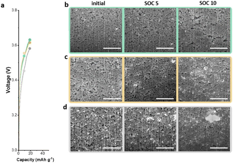 | ||
| Fig. 6 (a) Capacity–voltage profiles of full cells with SOC 5 and SOC 10. Cross-sectional SEM images display the initial state on the left, SOC 5 in the middle, and SOC 10 on the right: C@Ag-IC5 electrode (b), C@Ag-IC10 electrode (c), and C/Ag 25 electrode (d). | ||
Conclusions
In this study, an anodeless electrode with carbon-supported silver nanoparticles was prepared via thermal reduction of silver ion complexes during electrode fabrication. Compared with conventional physical mixing, this fabrication process achieved an improved dispersion of carbon and silver. The anodeless electrode with the Ag ion complex showed improved critical current density and lower overpotentials. Consequently, the pouch-type all-solid-state cell with an anodeless electrode exhibited excellent cycling stability, high coulombic efficiency, and good rate capability at low external pressure (4 MPa). This work provides a future direction for anodeless design and practical utilization for electric vehicle applications. In order to develop a more reversible all-solid-state battery, it is important to induce uniformity of the electrochemical reaction through uniform Ag distribution, and additional research is needed to maintain the distribution even in long-term cycle tests.Author contributions
Yun-Chae Jung: conceptualization, visualization, methodology, investigation, resources, writing – original draft, and writing –review. Chihyun Hwang: visualization, methodology, investigations, resources, and writing – original draft. Myung-Jun Kwak: visualization, methodology, investigation, and resources. Sang-Jin Jeon: methodology, investigation, and resources. Yun Jung Lee: methodology and resources. Won-Jin Kwak: methodology, resources, and writing – original draft. Hyun-Seung Kim: visualization, methodology, investigation, and resources. KyungSu Kim: methodology, investigation, and resources. Woosuk Cho: conceptualization, methodology, resources, project administration, and supervision. Ji-Sang Yu: conceptualization, methodology, resources, project administration, and supervision.Conflicts of interest
There are no conflicts to declare.Acknowledgements
This work was supported by the Ministry of Trade, Industry & Energy (MOTIE, Korea) (No. 20007045).References
- C. Wang, J. Liang, Y. Zhao, M. Zheng, X. Li and X. Sun, Energy Environ. Sci., 2021, 14, 2577–2619 RSC.
- W.-Z. Huang, C.-Z. Zhao, P. Wu, H. Yuan, W.-E. Feng, Z.-Y. Liu, Y. Lu, S. Sun, Z.-H. Fu, J.-K. Hu, S.-J. Yang, J.-Q. Huang and Q. Zhang, Adv. Energy Mater., 2022, 12, 2201044 CrossRef CAS.
- K.-N. Jung, H.-S. Shin, M.-S. Park and J.-W. Lee, ChemElectroChem, 2019, 6, 3842–3859 CrossRef CAS.
- K. H. Park, Q. Bai, D. H. Kim, D. Y. Oh, Y. Zhu, Y. Mo and Y. S. Jung, Adv. Energy Mater., 2018, 8, 1800035 CrossRef.
- R. Schmuch, R. Wagner, G. Hörpel, T. Placke and M. Winter, Nat. Energy, 2018, 3, 267–278 CrossRef CAS.
- J. Wu, L. Shen, Z. Zhang, G. Liu, Z. Wang, D. Zhou, H. Wan, X. Xu and X. Yao, Electrochem. Energy Rev., 2021, 4, 101–135 CrossRef CAS.
- T. Famprikis, P. Canepa, J. A. Dawson, M. S. Islam and C. Masquelier, Nat. Mater., 2019, 18, 1278–1291 CrossRef CAS PubMed.
- A. Manthiram, X. Yu and S. Wang, Nat. Rev. Mater., 2017, 2, 16103 CrossRef CAS.
- Y. Xiao, Y. Wang, S.-H. Bo, J. C. Kim, L. J. Miara and G. Ceder, Nat. Rev. Mater., 2020, 5, 105–126 CrossRef CAS.
- N. Kamaya, K. Homma, Y. Yamakawa, M. Hirayama, R. Kanno, M. Yonemura, T. Kamiyama, Y. Kato, S. Hama, K. Kawamoto and A. Mitsui, Nat. Mater., 2011, 10, 682–686 CrossRef CAS PubMed.
- Y. Kato, S. Hori, T. Saito, K. Suzuki, M. Hirayama, A. Mitsui, M. Yonemura, H. Iba and R. Kanno, Nat. Energy, 2016, 1, 16030 CrossRef CAS.
- Y. Jin, Q. He, G. Liu, Z. Gu, M. Wu, T. Sun, Z. Zhang, L. Huang and X. Yao, Adv. Mater., 2023, 35, 2211047 CrossRef CAS PubMed.
- X. Zhao, P. Xiang, J. Wu, Z. Liu, L. Shen, G. Liu, Z. Tian, L. Chem and X. Yao, Nano Lett., 2023, 23, 227–234 CrossRef CAS PubMed.
- Y. Lee, J. Jeong, H. J. Lee, M. Kim, D. Han, H. Kim, J. M. Yuk, K.-W. Nam, K. Y. Chung, H.-G. Jung and S. Yu, ACS Energy Lett., 2022, 7, 171–179 CrossRef CAS.
- P. Oh, J. Yun, J. H. Choi, K. S. Saqib, T. J. Embleton, S. Park, C. Lee, J. Ali, K. Ko and J. Cho, Angew Chem. Int. Ed. Engl., 2022, 61, e202201249 CrossRef CAS PubMed.
- A.-R. O. Raji, R. Villegas Salvatierra, N. D. Kim, X. Fan, Y. Li, G. A. L. Silva, J. Sha and J. M. Tour, ACS Nano, 2017, 11, 6362–6369 CrossRef CAS PubMed.
- J. Tao, Y. Chen, A. Bhardwaj, L. Wen, J. Li, O. V. Kolosov, Y. Lin, Z. Hong, Z. Huang and S. Mathur, Proc. Natl. Acad. Sci., 2022, 119, e2211059119 CrossRef CAS PubMed.
- J. Pu, J. Li, K. Zhang, T. Zhang, C. Li, H. Ma, J. Zhu, P. V. Braun, J. Lu and H. Zhang, Nat. Commun., 2019, 10, 1896 CrossRef PubMed.
- D. Zhang, A. Dai, M. Wu, K. Shen, T. Xiao, G. Hou, J. Lu and Y. Tang, ACS Energy Lett., 2020, 5, 180–186 CrossRef CAS.
- B. Liu, J.-G. Zhang and W. Xu, Joule, 2018, 2, 833–845 CrossRef CAS.
- S. Kim, C. Jung, H. Kim, K. E. Thomas-Alyea, G. Yoon, B. Kim, M. E. Badding, Z. Song, J. Chang, J. Kim, D. Im and K. Kang, Adv. Energy Mater., 2020, 10, 1903993 CrossRef CAS.
- L. Porz, T. Swamy, B. W. Sheldon, D. Rettenwander, T. Frömling, H. L. Thaman, S. Berendts, R. Uecker, W. C. Carter and Y.-M. Chiang, Adv. Energy Mater., 2017, 7, 1701003 CrossRef.
- Z. Zhang, J. Wang, Y. Jin, G. Liu, S. Yang and X. Yao, Energy Storage Mater., 2023, 54, 845–853 CrossRef.
- Y.-G. Lee, S. Fujiki, C. Jung, N. Suzuki, N. Yashiro, R. Omoda, D.-S. Ko, T. Shiratsuchi, T. Sugimoto, S. Ryu, J. H. Ku, T. Watanabe, Y. Park, Y. Aihara, D. Im and I. T. Han, Nat. Energy, 2020, 5, 299–308 CrossRef CAS.
- N. Suzuki, N. Yashiro, S. Fujiki, R. Omoda, T. Shiratsuchi, T. Watanabe and Y. Aihara, Adv. Energy Sustainability Res., 2021, 2, 2100066 CrossRef CAS.
- S. Cho, D. Y. Kim, J.-I. Lee, J. Kang, H. Lee, G. Kim, D.-H. Seo and S. Park, Adv. Funct. Mater., 2022, 32, 2208629 CrossRef CAS.
- S. Kim, J.-S. Kim, L. Miara, Y. Wang, S.-K. Jung, S. Y. Park, Z. Song, H. Kim, M. Badding, J. Chang, V. Roev, G. Yoon, R. Kim, J.-H. Kim, K. Yoon, D. Im and K. Kang, Nat. Commun., 2022, 13, 1883 CrossRef CAS PubMed.
- J. Oh, S. H. Choi, B. Chang, J. Lee, T. Lee, N. Lee, H. Kim, Y. Kim, G. Im, S. Lee and J. W. Choi, ACS Energy Lett., 2022, 7, 1374–1382 CrossRef CAS.
- J. Lee, S. H. Choi, G. Im, K.-J. Lee, T. Lee, J. Oh, N. Lee, H. Kim, Y. Kim, S. Lee and J. W. Choi, Adv. Mater., 2022, 34, 2203580 CrossRef CAS PubMed.
- S. Kim, M. Lee, S. Oh and W.-H. Ryu, Chem. Eng. J., 2023, 474, 145447 CrossRef CAS.
- L. Albero Blanquer, F. Marchini, J. R. Seitz, N. Daher, F. Bétermier, J. Huang, C. Gervillié and J.-M. Tarascon, Nat. Commun., 2022, 13, 1153 CrossRef CAS PubMed.
- J. Hu, Z. Sun, Y. Gao, P. Li, Y. Wu, S. Chen, R. Wang, N. Li, W. Yang, Y. Shen and S.-H. Bo, Cell Rep. Phys. Sci., 2022, 3, 100938 CrossRef CAS.
- Y. Chen, Z. Wang, X. Li, X. Yao, C. Wang, Y. Li, W. Xue, D. Yu, S. Y. Kim, F. Yang, A. Kushima, G. Zhang, H. Huang, N. Wu, Y.-W. Mai, J. B. Goodenough and J. Li, Nature, 2020, 578, 251–255 CrossRef CAS PubMed.
- S. Kim, G. Yoon, S.-K. Jung, S. Park, J.-S. Kim, K. Yoon, S. Lee and K. Kang, ACS Energy Lett., 2023, 8, 9–20 CrossRef CAS.
- S. H. Park, D. Jun, J. E. Jung, S. G. Lee, G. H. Lee and Y. J. Lee, J. Mater. Chem. A, 2022, 10, 21995–22006 RSC.
- Y. Fang, S. L. Zhang, Z.-P. Wu, D. Luan and X. W. Lou, Sci. Adv., 2021, 7, eabg3626 CrossRef CAS PubMed.
- H. S. Toh, C. Batchelor-McAuley, K. Tschulik, M. Uhlemann, A. Crossley and R. G. Compton, Nanoscale, 2013, 5, 4884–4893 RSC.
- D. H. S. Tan, Y. S. Meng and J. Jang, Joule, 2022, 6, 1755–1769 CrossRef CAS.
Footnote |
| † Electronic supplementary information (ESI) available. See DOI: https://doi.org/10.1039/d3ta05307e |
| This journal is © The Royal Society of Chemistry 2023 |