
 Open Access Article
 This Open Access Article is licensed under a
 Creative Commons Attribution 3.0 Unported Licence
Utilizing machine learning to optimize metal–organic framework-derived polymer membranes for gas separation†
Lena
Pilz
 a,
Carsten
Natzeck
a,
Jonas
Wohlgemuth
a,
Nina
Scheuermann
a,
Simon
Spiegel
a,
Simon
Oßwald
bc,
Alexander
Knebel
d,
Stefan
Bräse
bc,
Christof
Wöll
a,
Manuel
Tsotsalas
*ae and
Nicholaus
Prasetya
*a
a,
Carsten
Natzeck
a,
Jonas
Wohlgemuth
a,
Nina
Scheuermann
a,
Simon
Spiegel
a,
Simon
Oßwald
bc,
Alexander
Knebel
d,
Stefan
Bräse
bc,
Christof
Wöll
a,
Manuel
Tsotsalas
*ae and
Nicholaus
Prasetya
*a
aInstitut für Funktionelle Grenzflächen (IFG), Karlsruhe Institute of Technology (KIT), Campus Nord, Hermann-von-Helmholtz-Platz 1, Eggenstein-Leopoldshafen, 76344, Germany. E-mail: manuel.tsotsalas@kit.edu; nicholaus.prasetya@partner.kit.edu
bInstitut für Biologische und Chemische Systeme - Funktionelle Molekulare Systeme (IBCS-FMS), Karlsruhe Institute of Technology (KIT), Campus Nord, Hermann-von-Helmholtz-Platz 1, Eggenstein-Leopoldshafen, 76344, Germany
cInstitut für Organische Chemie (IOC), Karlsruhe Institute of Technology (KIT), Campus Süd, Fritz-Haber-Weg 6, D-76131, Karlsruhe, Germany
dFriedrich Schiller University Jena, Fraunhoferstr. 6, 07743, Jena, Germany
eDepartment of Chemical and Biological Engineering, Northwestern University, Evanston, IL 60208, USA
First published on 26th October 2023
Abstract
Metal–organic frameworks (MOFs) have gained substantial attention as promising materials for gas separation membranes due to their exceptional porosity, tailorability, and functionalizability. In this study, we present a novel approach to further enhance the properties of porous polymer membranes emerging from MOFs through crosslinking of the organic linker molecules and subsequent metal-atom removal. To ensure reproducibility of the multi-step synthesis process and high quality of the resulting polymeric membranes, we automated the process and followed a machine learning optimization approach. The high-quality MOF-thin films (SURMOFs) were prepared in a layer-by-layer fashion directly on gold-coated porous alumina substrates. This direct synthesis proved crucial to preserve the structural integrity of the membranes and thus avoiding defect formation caused by a substrate-transfer process, which is usually required when advanced materials are used to fabricate a membrane. The initial SURMOF membrane exhibits moderate gas separation performance, once crosslinked, its gas selectivity could be significantly enhanced although with the compromise of lower gas permeance. Interestingly, once we removed the metal centers and thereby converted the SURMOF into a purely organic polymeric membrane, the membrane gas permeance could be restored almost to its initial condition while preserving the enhanced selectivities. In particular, the resulting polymeric membrane outperforms most commercially available polymer membranes for H2/CO2 gas separation. This research outlines a promising approach to employ MOFs as template in the generation of advanced polymer membranes for various gas and liquid phase separation applications.
1 Introduction
Since its first industrial application in 1980 for hydrogen separation in an ammonia synthesis purge gas, a number of gas separation processes, such as hydrogen purification, biogas purification and air separation, became a promising area to expand the applicability of a gas separation membranes.1,2 Up to now, a gas separation membrane is usually fabricated using polymeric materials, since they are easy to process and generally inexpensive in comparison to other materials.3 However, polymeric membranes always suffer from the inverse relationship between the membrane permeability and selectivity as usually depicted through a Robeson upper bound.4 Therefore, a membrane with high gas permeability usually has low gas selectivity and vice versa.Addressing the above issues, various new materials such as covalent organic frameworks (COFs),5 graphene-based materials,6 MXenes,7 polymers of intrinsic microporosity (PIM),8 and thermally-rearranged polymers9 have been developed in the last few years to fabricate gas separation membranes including metal–organic frameworks (MOF).10,11 Furthermore, there has been a substantial amplification in the research dedicated to enhancing crystal crosslinking techniques and expanding the versatility of MOFs as adaptable templates, involving customized MOF-polymer composites, crosslinked polymers, and MOF crystals.12–16
MOFs are porous-hybrid materials, built from metal clusters connected by organic linkers, offering a host of benefits, distinguished by their heightened porosity, adaptable customizability, and the potential for framework functionalization.17,18 By virtue of these exceptional attributes, MOFs have emerged as a highly promising material for diverse separation processes and can also outperform conventional porous materials like activated carbon.19–22 Therefore, the use of these particular materials to improve the performance of a gas separation membrane has been widely investigated during the last few years.23
In general, there are two main approaches to fabricate a MOF-based membrane for gas separation.2,24 The first approach is to fabricate a mixed matrix membrane (MMM) where the membrane selective layer is constituted from at least two components: MOF nanoparticles and a polymer matrix.25–28 In this case, the MOF nanoparticles are incorporated as the discrete phase inside a polymeric matrix acting as the continuous phase. Differing from the first approach, the second method does not involve the utilization of a polymer matrix and the MOF is the only constituent of the membrane selective layer.29,30
In this study, we aim to develop a novel polymeric membrane material, called SURGEL, whose structural framework is inherited from the structure of a MOF and therefore can neither be classified as MMM nor MOF membrane. We develop this new SURGEL membrane by comprehensively investigating its development process consisting of SURMOF fabrication, crosslinking and metal atom removal. In this case, the foundation of the SURGEL membrane originates from a thoroughly crafted SURMOF (surface-anchored MOF) structure, meticulously built layer-by-layer through structured cycles. This method ensures the creation of remarkably high-quality thin films.31–33 This SURMOF grown on a porous substrate is then subjected to crosslinking and metal atom removal process, respectively, before becoming a SURGEL membrane.34,35 This innovative approach substantially enhances membrane stability, thereby holding tremendous promise for diverse applications, especially potential bioapplications.36–38 Within our context, the direct synthesis of the SURMOF membrane on a porous substrate before transforming it into the SURGEL is particularly crucial since this step obviates the necessity to employ a substrate-transfer process. For new and advanced membrane materials, this substrate-transfer process is sometimes necessary since the synthesis of these materials could be very delicate and thus requiring well-established substrate conditions that cannot be fulfilled by porous substrates, such as observed in MOF and COF membranes.39,40 By eliminating this substrate-transfer process, it is expected that the structural integrity of this new membrane material can be well preserved and thus yielding a new polymeric membrane material showcasing the satisfactory separation performance inherently owned to the MOF membranes.
In order to realize this objective, the rational design and optimization of the MOF synthesis condition becomes crucial to ensure the quality and reproducibility of the MOF as a starting material. In previous instances, machine learning and prediction techniques have demonstrated their substantial value in expediting the advancement of high-performance functional materials, as well as in optimizing specific parameters aligned with desired goals.41–44 Notably, an additional avenue for optimizing SURGEL's performance lies in the realm of high throughput computational screening.45 Given the widespread success of machine learning methods in optimizing parameters and conditions, our study employed a machine learning-based approach known as SynthesisConditionFinder, which was developed by Moosavi et al. in 2019.46 The primary objective was to optimize the synthesis conditions of a SURMOF based on the pillar-layered SURMOF-2 structure, utilizing a modified linker. As depicted in the Fig. 1, the goal of this optimization was to improve the stability and crystallinity of the SURMOF, as these are critical features, especially if the MOF is intended for use in gas separation processes. To overcome these obstacles, we also employed a synthesis robot to carefully control the synthesis parameters to minimize uncontrolled variations that could potentially impact the optimization process.
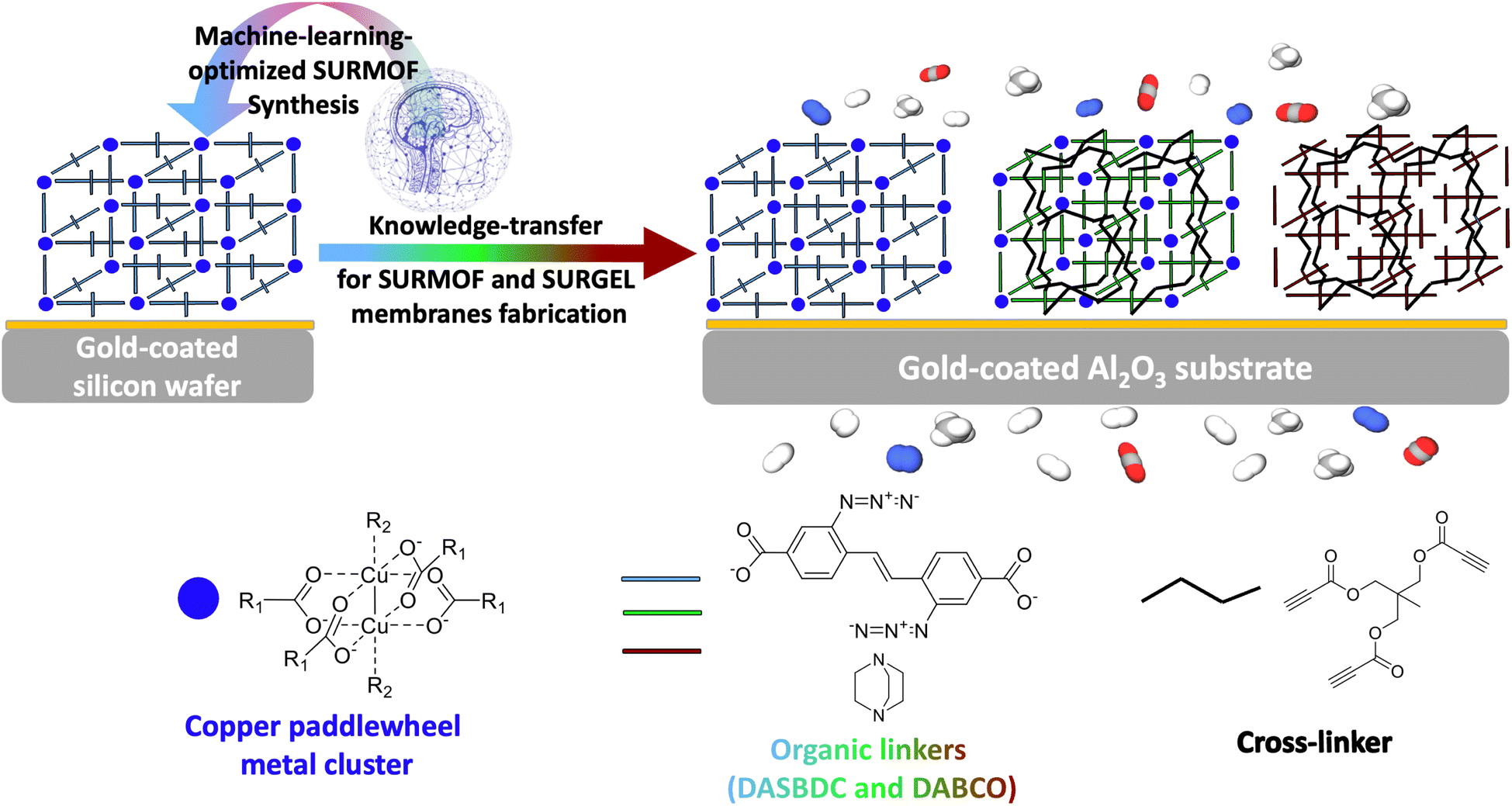 | ||
| Fig. 1 Schematic overview of the development of membranes for gas separation. First the SURMOF is optimized via machine learning on gold coated silicon wafers, then the optimized conditions are transferred on gold coated alumina substrates to fabricate a SURMOF, a crosslinked SURMOF and a SURGEL for gas separation investigation. | ||
The optimization process involved simultaneously varying five key synthesis parameters using a genetic algorithm provided by the SynthesisConditionFinder. Previous approaches to optimizing MOF thin film properties have primarily focused on varying a single parameter due to the complexity of multiparameter optimizations. However, this method does not fully capture the intricate relationship between synthesis conditions and film properties in the complex SURMOF synthesis process. Considering the multitude of parameters influencing MOF growth, it becomes imperative to simultaneously vary multiple parameters to achieve comprehensive optimization. Therefore machine learning methods appear very promising to address this challenge.47
The SyCoFinder tool consists of three consecutive steps aimed at optimizing synthesis parameters. In the initial step, known as the “Diverse Set,” the parameter space is defined along with the allowable intervals for parameter variation. To ensure a diverse range of parameter combinations, the MinMax method is employed. This method randomly selects a data point within the defined parameter space and then proceeds to choose subsequent points based on their maximum distance from each other. This approach guarantees comprehensive coverage of the parameter space with minimal samples. Experimental syntheses are then conducted based on the diverse parameter set, and the resulting outcomes are characterized. A fitness value, calculated through mathematical means using a fitness formula, is determined on a scale of 0 to 1 to assess the effectiveness of the parameter combinations.
In the second step, a new set of synthesis parameters is computed using a genetic algorithm, leveraging the information from the diverse set. The genetic algorithm facilitates the evolution and optimization of parameter sets across generations by considering the fitness values of parental chromosomes (i.e., different parameter sets) and recombining those that perform well. For a more comprehensive understanding of the genetic algorithm and the selection process through the MinMax procedure, we refer interested readers to the work of Moosavi and co-workers.46
Upon successful synthesis and characterization of the further developed parameter sets, along with calculating new fitness values, a new optimization cycle begins. The process continues until the characterization results meet the user-defined optimization criteria. In Fig. S8 in the ESI the entire workflow of the machine learning optimization is illustrated.† In the final step, once the optimization process concludes, all generated data are analyzed to determine the importance of variables. By following this iterative approach, the SyCoFinder tool enables the systematic exploration and optimization of synthesis parameters. It offers a comprehensive understanding of the parameter space and facilitates the identification of key factors influencing the desired outcomes.
By employing gold-coated silicon wafers as substrates, we firstly aimed to promote uniform nucleation and growth of the MOF crystals and comprehensively study the impact of various parameters on the quality of the MOF thin films. This approach not only facilitates the reproducibility of results but also enables the subsequent knowledge transfer when using different substrates such as the later employed gold coated alumina substrates as illustrated in Fig. 1. By leveraging the optimized synthesis conditions, high-quality MOF thin-films were also successfully synthesized on gold-coated alumina substrates, which are known for their exceptional porosity. The SURMOF growth on these substrates exhibits excellent compatibility with the optimized synthesis conditions initially employed for silicon wafers, confirming the robustness and versatility of our approach.
Upon the successful synthesis of a high quality SURMOF as the basis material, the study could then be safely followed by the crosslinking process and transformation into a SURGEL membrane, as a new polymeric membrane material. Since all the processes involved in the gas separation study were carried out exclusively on gold-coated alumina substrates, the delicate membrane transfer process from one substrate to another could be avoided.39,48 Such a direct conversion strategy is crucial to preserve the structural integrity of the membrane and prevent the emergence of defects that could be caused by a transfer process that would eventually negatively impact the membrane's performance.
In summary, this study highlights the successful optimization of synthesis conditions for a pillar layered SURMOF-2 system using a machine learning approach. The integration of a synthesis robot, gold-coated silicon wafers, and gold-coated alumina substrates enables the direct growth of MOFs and their subsequent processing into a new membrane material for gas separation membranes. The outcomes of this research contributes to the development of robust and efficient MOF-based membrane materials for various applications, particularly in gas separation technologies.
2 Experimental
2.1 Materials
The silicon wafers were purchased from Siegert Wafer, pre-cut by MaTecK and coated with gold by Georg Albert – PVD-Beschichtungen, Silz. The finished silicon wafer pieces then measure 1 × 3 cm2 in area and 525 nm in thickness with 100 nm gold coating on top. Meanwhile, the alumina substrates were purchased from Fraunhofer-Institut für Keramische Technologien und Systeme (IKTS). The diameter and thickness of the substrate is 18 mm and 1 mm, respectively, with average pore size of 70 nm.The linker 3-azido-4-[2-(2-azido-4-carboxyphenyl)ethenyl]benzoic acid and the crosslinker trimethylolethane tripropiolate were synthesized according to the literature.49
All other chemicals were obtained from commercial sources and used without further purification. Copperacetate dihydrate and 1,4-diazabicyclo[2.2.2]octane (DABCO) were used for synthesis and purchased from ACROS ORGANICS and Merck KGaA, respectively. Phenylbis(2,4,6-trimethylbenzoyl) phosphine oxide and 4-phenyldiazenylbenzene-1,3-diol (Sudan Orange G) which were used as initiator and as dye respectively in the 3D-printing process and purchased from Sigma Aldrich. FLUOROLINK® MD 700 was also used in for 3D-printing and purchased from Solvay. The solvents ethanol, methanol and toluene as well as acetone were used for synthesis and purification and purchased from AnalaR NORMAPUR and Merck KGaA respectively.
2.2 Fabrication of SURMOF
The chosen material for the sample holder is a viscous liquid based on a fluorinated methacrylate monomer, which undergoes solidification via UV curing during the printing process. The specific printing technique employed is referred to as Digital Light Processing (DLP), utilizing an Asiga Max UV DLP Printer. An image of CAD sketch as well as of the produced 3D-printed sample holder can be found in the ESI (see Fig. S7).†
All substrates were treated 72 h with a SAM-solution prior to the synthesis, containing 1.4 mg 16-mercaptohexadecanoic acid dissolved in 25 mL acetic acid (glacial) and 225 mL ethanol (99.8%).
| Variable | Range |
|---|---|
| c (linker) [mM L−1] | 0.01–1.00 |
| c (metal) [mM L−1] | 0.05–5.00 |
| Modulator (water) [mL] | 0.00–40.00 |
| DABCO [eq. of linker] | 0.10–2.00 |
| EtOH [%] (ratio to MeOH) | 0.00–100 |
According to these parameter sets the synthesis were carried out, characterized, and the resulting fitness was determined. The same parameter sets, along with their corresponding fitness values, were fed back into the web application, generating a new generation of parameter combinations to be synthesized, characterized, and ranked. This evolution of generations was repeated twice, resulting in thirty experiments in total, until satisfactory results were obtained.
The optimization process after the starting Diverse Set employed a genetic algorithm, involving recombination and mutation of the ranked parameter sets with the goal to achieve pure and highly crystalline DASBDC-SURMOF-thin films.
In the realm of machine learning optimizations, a significant volume of data is generated, much of which holds relevance for subsequent endeavors. When it comes to machine learning, it becomes crucial to retain data in machine-readable formats and even publish experiments that may not have yielded successful outcomes. This necessity underscores the importance of adopting a Research Data Management System. In the context of this study, the “Chemotion Repository” was employed, and all experimental data was made publicly accessible.50 This approach to data management contributes to the ethos of sustainable research practices.42,51
| Fitness = fitness (phase identity) × fitness (crystallinity) | (1) |
 | (2) |
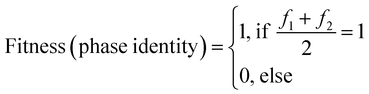
The fitness function fitness (phase identity), assesses the attainment of the desired compound by comparing the positions of measured diffraction peaks with a simulated diffractogram. A match between the patterns yields a fitness value of 1, indicating successful phase identification of two samples f1 and f2. Conversely, a lack of correspondence in either one or both samples f1 and f2 results in a fitness value of 0, causing the overall equation to evaluate to zero.
 | (3) |
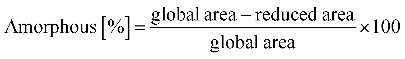
| Fitness (crystallinity) = 100 − amorphous% | (4) |
The fitness (crystallinity) parameter was determined by evaluating the overall and reduced areas of the diffractograms corresponding to the crystalline and amorphous regions. This assessment involved integrating the uncorrected and non-background-subtracted data to calculate the respective areas.
Returning to eqn (1), the initial fitness criterion (fitness (phase identity)) serves as a binary indicator, determining whether an experiment is included in the evaluation. The second criterion (fitness (crystallinity)) then assigns the numerical rating between 0 and 1, representing the actual quality of the experiment.
2.3 Fabrication of crosslinked-SURMOF (SURMOF-CL)
The crosslinking of the MOF structure was achieved using a solvothermal method based on the literature.49 Therefore, the thin film samples were immersed in a crosslinker solution containing 1 mg mL−1 trimethylolethane tripropiolate in toluene and heated to 80 °C for one week. For purification, the samples underwent rinsing with both ethanol and acetone, after which they were stored under ambient conditions until further processing. To ensure no crystallinity was lost during this process all samples were analyzed via XRD.2.4 Fabrication of SURGEL
For the conversion of the crosslinked samples on gold coated silicon substrates into a SURGEL the metal-knodes were removed by treatment with 1 mg/10 mL EDTA (ethylene diaminetetraacetic acid disodium salt) in a 1![[thin space (1/6-em)]](https://www.rsc.org/images/entities/char_2009.gif) :1 mixture of ethanol and water for 3 hours.
:1 mixture of ethanol and water for 3 hours.
The same procedure was applied for the samples on gold-coated alumina substrates except for the ratio of EDTA was set to 1 mg/5 mL. Also the immersion time was set to one week due to the high porosity and therefore slower diffusion rate through the alumina substrates.
To confirm the complete conversion by verifying the entire absence of crystallinity, all samples were analyzed via XRD.
2.5 Materials characterizations
To ensure comparability, each measurement underwent height error correction and background correction using DIFFRAC.EVA software version 5.2.0.3 provided by Bruker AXS. The evaluation of crystallinity was performed using a built-in routine by Bruker. For assessing phase identity, the obtained diffractograms were compared to a simulated powder diffractogram.
2.6 Measurement of the gas separation performance
The gas separation performance of the SURMOF, SURMOF-CL and SURGEL was evaluated using a Wicke–Kallenbach setup. Before the gas permeation experiment was performed, the sample was pre-conditioned by mounting it inside the membrane permeation cell first where the nitrogen and helium (50 mL min−1) were continuously introduced on the feed and permeate side, respectively, for at least 18 hours. This ensured that the samples were dried under controlled conditions with minimal exposure to the surrounding atmosphere. Afterwards, the gas permeation was measured by feeding the pure gases of H2, CH4, N2, and CO2 was fed to the membrane at the flow rate of 50 mL min−1. Meanwhile, argon was used as the sweep gas on the retentate side with the flow rate of 10 mL min−1. The gas permeance of the membranes was evaluated by Varian micro gas chromatograph (GC) CP-4900. The micro GC used argon as the carrier gas and was equipped with molsieve and PPQ columns. The gas permeance was measured at least 5 times until a stable reading was obtained.3 Results and discussions
3.1 Fabrication of SURMOF, crosslinked-SURMOF and SURGEL
The first step, the “Diverse Set”, mainly produces parameter combinations from the limit values chosen as minimum and maximum, respectively, to delineate the boundaries of the defined parameter space. Taking this into account the main machine learning part is performed within the two generations of genetic algorithm (GA1 and GA2), taking the data produced in the diverse set as starting data set. This is also directly reflected in the data points in Fig. 2a visualizing the development over the different generations: the first generation (Diverse Set) resulted in six diversely spread but low ranging experiments, the second generation (Genetic Algorithm 1) led to three and the third generation (Genetic Algorithm 2) again to six successful experiments. The fitness of the successful experiments, however, increases strongly with the second generation (GA1), showing the high effectiveness of the genetic algorithm, but the successful rated experiments are still very few. Accordingly, the increase to the third generation is no longer as strong, but the number of successful experiments with very good performance or fitness increases. In addition, there are no more experiments with a fitness value below 83%. Thus, the optimization is evaluated as successful, also in consideration of several very good experiments with fitness values up to 94% in the best experiment.
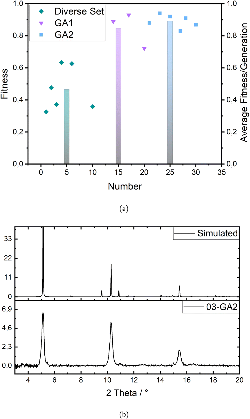 | ||
| Fig. 2 (a) Fitness development over three generations; the data points represent the fitness value for each experiment with green rhombuses for the diverse set, purple triangles for the first genetic algorithm (GA1) and blue squares for the second genetic algorithm (GA2); the bars show the average fitness of the successful experiments per generation in the same color code. (b) Exemplary X-ray diffractograms showing the comparison of a measured sample (03-GA2) with a simulated diffractogram. | ||
The evaluation of the fitness has been performed via analysis of X-ray diffractograms. First, the formation of the correct structure is determined by comparing the measured signals to the position of signals in a simulated diffractogram. This simple binary criterion, named phase identity results either in the exclusion or consideration for further evaluation. From the robotic synthesis set-up always two samples per synthesis are produced in one experiment providing system inherent information about the reproducibility of a set of parameters. Each sample f1 and f2 is analyzed and rated with the value one for a positive match with the simulation and zero if either no crystalline structure or the wrong structure was built, including multiple phases identified by doubled and shifted signals. If both samples of a parameter combination perform similar in terms of signal-positions the fitness (phase identity) equals one as indicated in eqn (2). If none or only one of two XRD measurements matches the simulation the whole criterion is rated zero, to ensure only reproducible samples are included. In the most recent generation (GA2) however, X-ray diffraction measurements were conducted on only one sample per synthesis. The second sample was reserved for subsequent investigations.
Since the syntheses are performed under controlled conditions, such as humidity and atmosphere (nitrogen/ethanol), and executed by an industrial six-axis robot, both samples of a parameter combination always showed either the same or no crystalline signals, which indicates the high reproducibility of the applied synthesis method. Fig. 2b shows an example of the comparison of a measured X-ray diffractogram and the simulation, which in this case agree very well. Over the whole optimization 15 experiments were agreed to show the correct signals and therefore considered for further investigation on crystallinity.
The fitness (crystallinity) evolves also from the X-ray diffractograms as a percentage value providing the actual rating of the experiments. The calculation of this fitness value is shown in eqn (3) and (4) and all diffractograms are to be found in the ESI (see Fig. S1–S5†) as well as the crystallinity values according to every experiment and their corresponding fitness values (see Tables S4–S6).† In the first generation there are six successful experiments but only ranging between 33% and 63% crystallinity and therefore averaging only 47%. With the second generation (GA1) the crystallinity rises up to values between 72% and 93% averaging 85% but with only three of ten experiments being successful at all. The third generation, however, reaches six successful experiments averaging 89% with no value below 83% and up to 94% crystallinity. With this the machine learning optimization is considered successful.
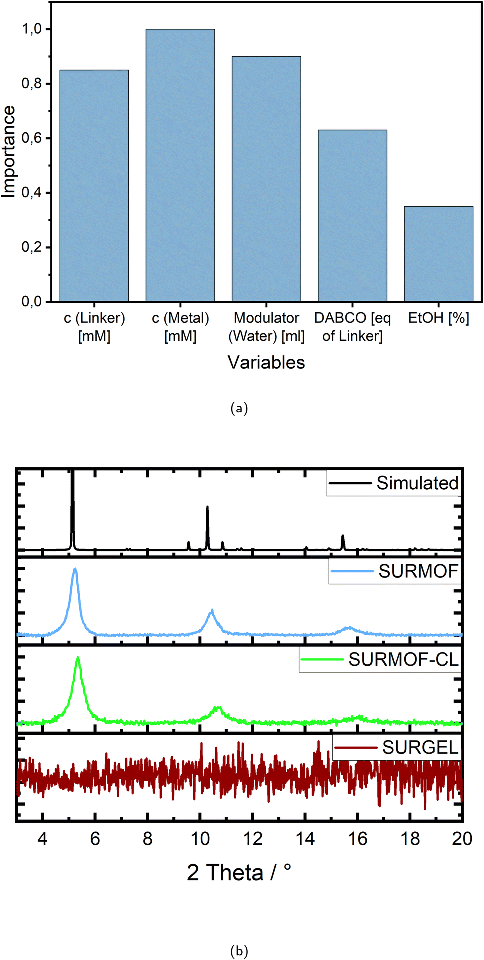 | ||
| Fig. 3 (a) Importance of variables for the five chosen variables c (linker), c (metal), modulator (water), DABCO (additive) and ethanol (solvent) in relative values between 0 and 1. (b) XRD of SURMOF, SURFMOF-CL and SURGEL. | ||
However, it is also helpful to gain some insights about the system by studying the graph along with the fitness values and parameters of the successful experiments. In Table 2 all successful parameter sets are shown, ordered by decreasing fitness.
| Fitness | c (linker) [mM L−1] | c (metal) [mM L−1] | Modulator (water) [mL] | DABCO [eq. of linker] | EtOH [%] |
|---|---|---|---|---|---|
| 0.94 | 0.70 | 0.56 | 40 | 1.36 | 24 |
| 0.93 | 0.84 | 0.05 | 40 | 1.43 | 26 |
| 0.92 | 0.60 | 2.35 | 22 | 0.74 | 49 |
| 0.91 | 0.78 | 5.00 | 36 | 1.87 | 100 |
| 0.89 | 1.00 | 5.00 | 40 | 2.00 | 100 |
| 0.88 | 0.51 | 5.00 | 19 | 1.26 | 100 |
| 0.87 | 0.92 | 4.89 | 15 | 1.47 | 91 |
| 0.83 | 0.87 | 5.00 | 40 | 2.00 | 100 |
| 0.72 | 0.78 | 5.00 | 36 | 1.87 | 100 |
| 0.63 | 1.00 | 0.05 | 40 | 0.10 | 50 |
| 0.63 | 0.01 | 5.00 | 40 | 1.05 | 0 |
| 0.48 | 1.00 | 5.00 | 40 | 2.00 | 100 |
| 0.37 | 0.01 | 0.05 | 20 | 2.00 | 100 |
| 0.36 | 0.01 | 2.52 | 40 | 0.10 | 100 |
| 0.33 | 0.01 | 0.05 | 0 | 0.10 | 0 |
Taking a closer look at the variables and their importance, the first thing that becomes noticeable is that all variables except for the percentage of ethanol as reaction solvent inherit an importance of more than 0.6, indicating a high impact on the successful outcome. The remarkably high values for the importance of linker and metal salt are intrinsic to the system, since they are generally required for structure formation and therefore crystallinity.
However, looking at the concentration values for each variable individually, it becomes clear that the “importance” of the linker requires using a rather high concentration, as almost all experiments with a fitness above 0.5 show a concentration of more than 0.5 mM L−1, mostly even more than 0.7 mM L−1, with 1 mM L−1 being the maximum (see Table 1).
Although in terms of the metal salt the concentration values seem to be distributed without accumulation in a certain value range, but they correlate strongly and approximately linear with the percentage of ethanol for all experiments with a high fitness. However, since the experiments appear to be successful at different amounts of ethanol/methanol mixture, as indicated by the low significance of this variable in Fig. 3a, it stands to reason that the values for the metal salt may also vary widely.
In almost all cases the modulator water is added with more than 20 mL mostly even more than 30 mL, with 40 mL being the maximum and 0 mL the minimum. Only one experiment without water was successful at all, reaching a fitness of only 0.33. The importance in this case is therefore referring to a high amount of modulator.
Regarding the additive DABCO the importance is relatively speaking less than the ones of the concentrations and the modulator, but still more than 0.6. It is again quite clear, that importance in this case means adding amounts in the upper ranges of the variables borders (see Table 1), since only three experiments appear with very low values of 0.1 equivalents of the linker and those achieve only fitness values in the lower ranges. Almost all high rated experiments contain more than one and up to two equivalents.
So far the sample holder for the robotic synthesis system was made of Teflon, which is chemically inert and therefore suitable for a broad range of solvents. With this the rectangular silicon substrates were mounted into a gripper with one end which was therefore not covered with the reaction solutions during the synthesis. To produce a defect-free membrane however, it was necessary to cover the whole surface of the alumina substrates which are in addition round to fit into the gas separation device. Therefore a new sample holder with complex requirements was designed. The shape was chosen to touch as little of the surface as possible, and the material had to be flexible to ensure damage-free clamping, but still securely fix the sample for the synthesis process and should be as inert as possible to the reaction solutions. Due to this complex task and also for environmental reasons, methanol was no longer used. Moreover, our previous assessments of variable importance have highlighted that, among the chosen factors, the ratio of methanol to ethanol as solvent mixture exerts the least influence on attaining stable and highly crystalline SURMOF structures, making it readily adjustable. Therefore, among the best syntheses, the one containing only ethanol was selected to apply the optimized parameters to the porous alumina substrates, still achieving a fitness of 91%.
The X-ray diffraction pattern of the SURMOF in Fig. 3b demonstrates the successful transfer of the chosen synthesis conditions from the silicon to the alumina substrate, achieving a very similar crystallinity of 93%. The subsequent crosslinking procedure with trimethylolethane tripropiolate was likewise successful. In Fig. 3b it is evident that the crystallinity remains stable (see SURMOF-CL), which is also proven by the calculation according to eqn (3) and (4), providing a crystallinity value of 88%. With the transformation to the SURGEL however, the crystallinity is then completely removed, since the metal knodes are etched away by EDTA and the intercrosslinked polymeric structure remains. All three stages as well as the bare gold coated substrates surface are recorded by SEM images which are to be found in the ESI (see Fig. S9).†
3.2 Gas separation performance of SURMOF, crosslinked-SURMOF and SURGEL
Having successfully fabricated the SURMOF, crosslinked-SURMOF (SURMOF-CL) and SURGEL on a gold-coated porous alumina substrate, the gas separation performance of these membranes were investigated. Before proceeding with the measurement, first the gas permeance of the gold-coated alumina substrate was examined. As can be seen in Table S7 in the ESI,† the gas selectivities of the gold-coated alumina substrate is almost 1 in all cases and thus indicating non-selective gas permeation behavior. Meanwhile, a contrasting situation can be observed once the substrate is coated with either SURMOF, SURMOF-CL or SURGEL membrane, whose gas separation performance results are presented in Fig. 4a.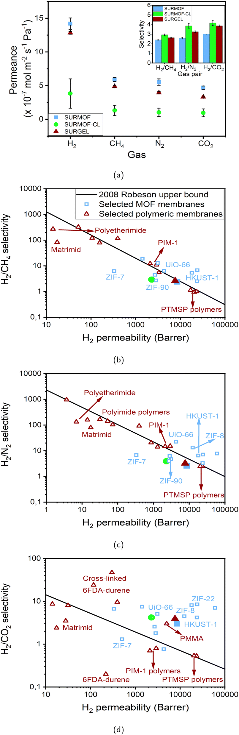 | ||
| Fig. 4 (a) Gas permeance and gas selectivity (inset) of SURMOF, SURMOF-CL and SURGEL membranes. (b) H2/CH4, (c) H2/N2 and (d) H2/CO2 gas separation performance comparisons of SURMOF, SURMOF-CL and SURGEL membranes against selected MOF membranes30,54–65 and polymeric membranes.4,66–88 The legends in the figures (a) and (b) apply for all the figures. | ||
As demonstrated by the results, the gas permeance of all membranes follows the same trend with H2 as the fastest permeating gas in all cases due to its comparably smaller size regarding the other gases. Afterwards, the gas permeance of the membranes follows the order of CH4, N2 and CO2. This then indicates that the gas permeance in SURMOF, crosslinked-SURMOF and SURGEL is governed by the molecular weight (MW) of the permeating gas, namely gas with higher MW permeates slower than gas with lower MW.
The gas transport through a membrane could actually be described by various mechanisms.2,52 In a dense-polymeric membrane, the gas transport is usually described by a solution-diffusion model.52,53 In this case, the gas is assumed to be condensed at the feed side of the membrane, get dissolved and diffuses across the membrane to the permeate side. Meanwhile, in a porous membrane, the gas transport can be governed by at least three different mechanisms: convective flow, Knudsen diffusion and molecular sieving. When a gas separation membrane contains a significant number of defective sites, whose pore size is more than 50 nm, its gas transport is dictated by convective flow mechanism. In contrast, the gas transport in a least-defective membrane can be governed either by Knudsen diffusion or molecular sieving, depending upon the pore size of the porous membrane. A molecular-sieving membrane can be obtained when the porous membrane has a very tight pore size which can effectively discriminate the permeating gases based on their molecular size. Meanwhile, when the pore size of the membrane is slightly bigger than the molecular sieving scenario, the gas transport is governed by the Knudsen diffusion where the gas permeance follows the order of the MW of the gases. Therefore, it can be safely inferred that the gas transport in all cases of our membranes follows the Knudsen diffusion model rather than a molecular sieving since the rate of the gas permeance follows the order of the MW of the gases rather than their kinetic diameter. Since the gas transport follows the Knudsen diffusion model, we can also evaluate the performance of the membranes with the ideal scenario where the pinholes are absent in the membrane. In the Knudsen diffusion model, the ideal gas selectivity of H2 against CH4, N2 and CO2 is 2.82; 3.74 and 4.7, respectively.
In this cases, as can be seen from the inset of Fig. 4a, the selectivity of the membranes follows the order of SURMOF-CL, SURGEL and SURMOF. The selectivity of H2 against CH4, N2 and CO2 of the SURMOF membrane is found to be around 2.4; 2.6 and 3, respectively. Based on these results, it can be seen that a non-ideal Knudsen diffusion scenario occurs in the SURMOF membrane. This can then be associated with two main reasons. First, the pore size of the SURMOF membrane is not adequate to perform such a sieving effect. According to the computational calculation that was previously performed,49 the pore size of the SURMOF membrane is around 1 nm. This is significantly larger than the gases used in this study and also around 10% larger than the pore size of HKUST-1, where Knudsen diffusion selectivity can not also be achieved.54,55,59 Therefore, it is safe to assume that the relatively large pore size of the SURMOF membrane plays a crucial role to the emergence of the non-ideal gas diffusion scenario. The second reason might also be associated with the presence of a few pinholes within the SURMOF membrane. Even though the surface of the SURMOF membrane looks homogeneous, the presence of tiny defects could not be completely eliminated which also contributes in amplifying the impacts coming from the convective flow. Therefore, together with the big pore size of the SURMOF membrane, both conditions then lead to the non-ideal scenario of gas diffusion occurring inside the SURMOF membrane.
Once the SURMOF membrane was inter-crosslinked, a significant improvement in the gas selectivities is observed and the selectivity of H2 against CH4, N2 and CO2 now approaches the Knudsen ideal values, namely 2.9; 3.9 and 4.2, respectively. This corresponds to the performance improvement of around 21%, 50% and 40%, respectively, in comparison to the SURMOF membrane. Such a remarkable performance improvement could then be associated with two main phenomena. First, the crosslinking process might contribute in tightening the pore aperture of the SURMOF membrane. As illustrated in Fig. 5b, this phenomenon occurs due to the reactive groups of the crosslinkers connecting the SURMOF ligands to each other by reacting with the azide group of the ligands and thus resulting in membranes with smaller pore size. Second, this crosslinking process might not also exclusively occur within the SURMOF's pores but also between the MOF crystallites. In this case, the crosslinking process might contribute in reducing the defect densities in the membrane. Therefore, it is assumed that both the SURMOFs pore tightening and defect density reduction contribute in significantly enhancing the gas selectivity of the SURMOF-CL membrane and thus can achieve an almost ideal Knudsen diffusion scenario. However, such an improvement must also be accompanied with lower gas permeance since the diffusion of the gases is now more obstructed by the presence of the crosslinkers in the pores. As can be seen from Fig. 4a, the H2 gas permeance of the SURMOF-CL membrane is around 4.1 × 10⁻⁷ mol m−2 s−1 Pa−1, which is around three times lower than the SURMOF membrane.
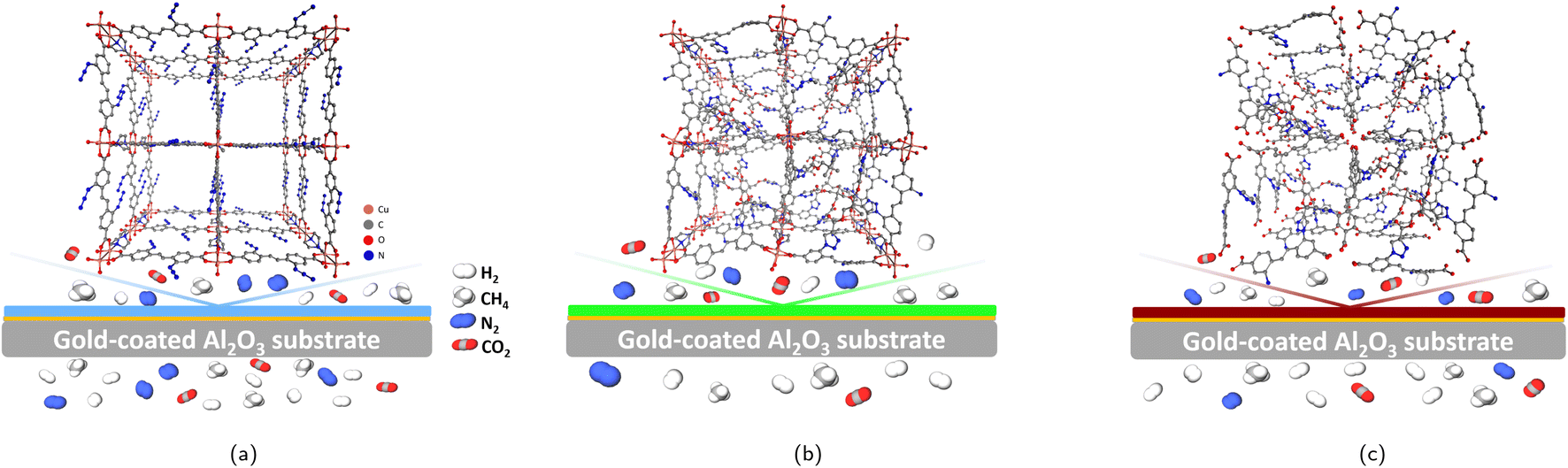 | ||
| Fig. 5 Illustration of the unit cell and the membrane performance of the SURMOF (a), SURMOF-CL (b) and SURGEL (c). | ||
Finally, when the crosslinked SURMOF (SURMOF-CL) was transformed into the SURGEL membrane, the selectivity of H2 against CH4, N2 and CO2 decreased slightly and was now found to be about 2.6; 3.3 and 3.9, respectively. This corresponds to the membrane selectivity decrease around 10%, 15% and 7%, respectively, from the SURMOF-CL membrane. Despite this decrease in performance, the gas selectivity of the SURGEL membrane is even higher than the SURMOF membrane. In particular, the H2 selectivity against N2 and CO2 of the SURGEL membrane is around 30% higher than the SURMOF membrane. Interestingly, such a slight decrease in the gas selectivity from the SURMOF-CL membrane is also accompanied by significantly higher gas permeance observed in the SURGEL membrane. As shown in Fig. 4b, the H2 gas permeance of the SURGEL membrane is found to be around 12.8 × 10⁻⁷ mol m−2 s−1 Pa−1, which is only around 10% lower than the H2 permeance of the SURMOF membrane.
The relatively high gas permeance of the SURGEL membrane with better gas selectivity compared to the SURMOF membrane could be associated with a number of phenomena. As has been previously explained, the transformation process of a SURMOF-CL membrane into a SURGEL membrane is accompanied by the loss of the crystallinity and thus resulting in an amorphous material. Because of this transformation, it firstly can be argued that the gas transport is now governed by the solution-diffusion phenomenon as it is the case for most polymeric membranes. However, it should also be noted that the SURGEL membrane has different characteristics than a conventional polymeric membrane, since the fabrication of a SURGEL membrane is initialized by a SURMOF membrane fabrication. Therefore, to some extent, its structure is still determined by the SURMOF structure. With respect to this, it can be hypothesized that the porous structure possessed by both SURMOF and SURMOF-CL membranes is also be inherited once the membrane is transformed into a SURGEL membrane. As illustrated in Fig. 5c, upon the removal of the copper metal from the SURMOF-CL, the porous structure of the SURMOF-CL can still be maintained. This is due to the crosslinker having three reactive groups being able to not only binding the SURMOF ligands located in the same layer, but also those located in different layers (inter-layer binding). Therefore, once the copper ion is removed from the SURMOF-CL, the SURGEL membrane can still maintain its porous-3D structure, where the crosslinker acts as the scaffold. Secondly, the removal of copper atoms from the SURMOF-CL also leaves additional gaps in the SURGEL membrane. Maintaining the porous structure in the SURGEL membrane with additional gaps remaining after removal of the copper ion could then help improve gas permeability compared to the SURMOF-CL membrane.
Meanwhile, the decrease in the gas selectivity in the SURGEL membrane, in contrast to the SURMOF-CL membrane, might be associated with the presence of some bigger pore aperture in the SURGEL. When the copper ion is removed from the SURMOF-CL membrane, the coordination bonding between the aromatic ring of the linker and the copper atom is also removed. As a consequence, the aromatic rings have now more rotational degrees of freedom and thus resulting in larger gaps within the SURGEL membrane that do not previously exist in the SURMOF-CL membrane. Despite this, such a rotation might also be limited because the linker molecules are already crosslinked with each other. As a result, no striking decrease in the gas selectivity does occur and the SURGEL membrane can still maintain a satisfactory performance.
Lastly, to give a broader perspective on the gas separation performance of the SURMOF, SURMOF-CL and SURGEL membranes, their performance against some selected MOF and polymeric membranes is given in Fig. 4b–d. In this case, the gas permeability of SURMOF, SURMOF-CL and SURGEL membranes was estimated based on around 2 µm membrane thickness (see Fig. S10 in the ESI†). From the result, it can firstly be seen that the performance of the SURMOF membrane could be considered moderate in our case if its performance is compared with other MOF membranes, in particular for H2/N2 separation. As can be seen, the performance of the SURMOF cannot surpass the Robeson upper bound as in the case for various well-known MOF membranes such as HKUST-1,54,55 UiO-66 (ref. 58) and ZIF-8.57 Meanwhile, the performance of the SURMOF membrane applied for H2/CH4 and H2/CO2 separations are slightly better since it can now surpass the upper bound, in particular for the latter case. However, with only around 9000 barrer H2 permeability, the performance of our SURMOF membrane is still not as high as in the case of, for example, HKUST-1,54,55 ZIF-8 (ref. 57) and ZIF-22,56 whose H2 permeability could reach more than 10000 barrer and thus placing them at almost the upper right for region for H2/CO2 separation process.
Once crosslinked, the performance of the SURMOF-CL moves to the upper left direction of the graph and thus indicating the decrease in the membrane permeability with an increase in the selectivity. Despite such separation performance increase, the performance of the SURMOF-CL is still relatively moderate. For example, as can be seen in the Fig. 4b and c, the performance of the SURMOF-CL for H2/CH4 and H2/N2 separation has moved further from the upper bound even though its selectivity has been significantly improved from the SURMOF membrane. Meanwhile, in the case of H2/CO2 separation process, even though the separation performance of the SURMOF-CL is still above the upper bound, the performance of most MOF membranes are still better than the SURMOF-CL. Therefore, from this comparison study, it could be safely inferred that the performance of both the SURMOF and SURMOF-CL membranes could not really outperform the current gas separation performance obtained in various well-known MOF membranes. Even though both membranes have shown high gas permeability, the relatively big pore aperture of this particular MOF could not really promote the molecular sieving effect observed in other MOFs whose pore size are below 1 nm.
However, a contrasting situation can be observed once we compare the performance of the SURGEL with some well-known polymeric membranes. As can be seen from Fig. 4b–d, once the SURMOF-CL has been transformed into a SURGEL membrane, the H2 permeability of the membrane moves again to the right-hand side direction and gets close to the initial SURMOF H2 permeability. Although the selectivity of the SURGEL membrane is slightly less than the SURMOF-CL membrane, the overall performance of the SURGEL membrane looks more promising than most of the commercially-available and recently-developed polymers such as Matrimid,68 polyetherimide (PEI),69 poly(methyl methacrylate) (PMMA),70 and polymer of intrinsic microporosity 1 (PIM-1).71 In this respect, PTMSP is one example of the polymers whose performance is quite close to the SURGEL membrane, even though this particular polymer has suffered from relatively low gas selectivity (around 1 for all the cases).79
As discussed above, such a high gas permeability and moderate gas selectivity could be mostly contributed from the highly porous structure of the SURGEL membrane because it is developed based on the SURMOF membrane with relatively large pore size. Therefore, differing from the cases observed in dense polymeric membranes, the gas molecules in the SURGEL membrane could diffuse faster with less resistance through the interconnected pores of the SURGEL membrane. In this case, the gas permeability of the SURGEL membrane resembles more the behavior as observed in rubbery polymers where higher diffusivity usually occurs.89 However, differing from the most common rubbery polymers whose selectivity is usually determined by the gas solubility rather than diffusivity,90 the diffusion process in the SURGEL membrane also contributes in determining its selectivity, namely through the Knudsen diffusion process. As a result, it has better separation performance in comparison to other rubbery polymers such as PTMSP and more selectivity towards H2.79 Such a good combination between the high H2 gas permeability and satisfactory gas selectivity in a polymeric membrane can be particularly useful when a H2 selective membrane is required. In this case, it can be seen from the result that the SURGEL membrane could be particularly promising when it is deployed for H2/CO2 separation process since its performance significantly surpasses the 2008 Robeson upper bound. In comparison to other polymeric membranes that also have surpassed the upper bound for the same purpose, such as in the case of cross-linked 6FDA-durene,86–88 the SURGEL membrane could offer up to around one order of magnitude higher gas permeability with satisfactory selectivity without the requirement to operate the membrane at elevated temperature as previously conducted in PBI-based polymeric membranes to surpass the upper bound.91 Finally, it is also worth to mention that, in comparison to MOF membranes, a transformation process from the SURMOF into the SURGEL membrane could greatly improve the material stability since the SURMOF has now been converted into a covalently-bound polymeric network.37 Such an improvement in the material stability could then be considered as an alternative and promising way to fully exploit the potential application of advanced materials developed from MOFs. In this case, combined with high gas permeance/permeability and satisfactory gas selectivity, the use of the SURGEL membrane in real situations is indeed preferable since the capital cost could also be significantly reduced by having membrane systems of smaller sizes.90
4 Conclusions
In this study we have successfully developed a new polymeric membrane material called SURGEL by firstly fabricating a SURMOF membrane followed by crosslinking and atom removal process. We employed an automated synthesis process combined with machine learning optimization to ensure reproducibility and high quality throughout the complete process. The optimization was performed within thirty experiments or two generations of machine learning, respectively, revealing important insights and a comprehensive understanding of the synthesis dependencies in the layer-by-layer SURMOF synthesis. The subsequent crosslinking process yielded SURMOF-CL membranes with preserved crystallinity of the templating SURMOF. Finally, the transformation of SURMOF-CL membranes into SURGEL membranes resulted in an purely organic polymeric network structure. The direct growth of the membranes on porous substrates not only circumvented the risk of damage that may occur during the substrate transfer process but also ensured full substrate coverage.The successful direct synthesis of SURMOF, SURMOF-CL and SURGEL membranes on porous substrates enabled the systematic study of their gas separation performance. In the case of the SURMOF membrane, its gas separation performance is comparable with other MOF membranes of comparable pore aperture such as HKUST-1. The gas separation performance of the SURMOF membrane can then be substantially enhanced after the cross-linking process, likely caused by the reduced pore size. However, this enhanced selectivity was accompanied by reduced permeability. In contrast, the transformation of the SURMOF-CL into the polymeric (SURGEL) membrane can combine both high gas permeability and good selectivity with performance well above most of the commercially available polymeric membranes. The relatively high gas permeability of the SURGEL membrane resembles similarities with rubbery polymers. The gases could diffuse relatively fast through the SURGEL membrane because of the presence of the additional void spaces within the SURGEL structure after the removal of the metal ions. However, differing from the rubbery polymers, the gas selectivity in the SURGEL membrane still follows the Knudsen behaviour since the SURGEL membrane could maintain, to some extent, the well-defined pores of the original SURMOF membrane. In particular, the performance of the SURGEL membrane for H2/CO2 separation is considerably better than other polymeric membranes since it can well surpass the 2008 Robeson upper bound limit. Even though the fabrication process of a SURGEL membrane looks more complicated than the fabrication of a MOF membrane or a MOF-MMM, there are two advantages offered by this approach. First, the gas separation performance exhibited by the SURGEL membrane looks more promising than most polymeric membranes because of its the retainment of the well-defined structure from the SURMOF. Second, the transformation of the SURMOF into SURGEL could improve the material stability since the SURMOF has now been converted into a more stable polymeric network. Both advantages could then be considered as the merit for its further development. In particular, this study has successfully shown how automation and machine learning can be used to optimize the production of this new, advanced and high-performance polymeric membrane for gas separations.
Author contributions
L. P.: conceptualization, methodology, formal analysis, investigation, data curation, writing – original draft, writing – review & editing, visualization. C. N.: investigation, writing – review & editing. J. W.: investigation, writing – original draft, writing – review & editing. N. S.: investigation, writing – review & editing. S. S.: writing – review & editing, visualization. S. O.: investigation, writing – review & editing. A. K.: investigation, writing – review & editing. S. B.: resources, writing – review & editing, supervision. C. W.: resources, writing – review & editing, supervision. M. T.: conceptualization, resources, writing – review & editing, project administration, supervision, funding acquisition. N. P.: conceptualization, methodology, validation, formal analysis, investigation, resources, data curation, writing – original draft, writing – review & editing, visualization, project administration, funding acquisition.Conflicts of interest
There are no conflicts to declare.Acknowledgements
N. P. acknowledges the funding from the Alexander von Humboldt Postdoctoral Fellowship (Ref 3.3 – GBR – 1219268 – HFST-P). M. T. acknowledges the support by the DACStorE project, funded by the Initiative and Networking Fund of the Helmholtz Association (grant agreement number KA2-HSC-12). The authors also acknowledge the support from the Cluster of Excellence 3D Matter Made to Order (3DMM2O). In addition, the authors would also like to thank Nicole Jung (IOC, Karlsruhe Institute of Technology) and the Chemotion development team for their outstanding cooperation and support and Dr Aline Leon and Mr Alessandro Micero from Europäisches Institut für Energieforschung (EIFER) for lending the micro GC to carry out this experiment. The authors initially utilized Chat-GPT to draft certain sections of the manuscript based on keypoint lists; however, these portions were subsequently entirely reworked by the authors themselves.References
- R. W. Baker and B. T. Low, Macromolecules, 2014, 47, 6999–7013 CrossRef CAS.
- N. Prasetya, N. F. Himma, P. D. Sutrisna, I. G. Wenten and B. P. Ladewig, Chem. Eng. J., 2020, 391, 123575 CrossRef CAS.
- K. K. Wong and Z. A. Jawad, J. Polym. Res., 2019, 26, 289 CrossRef CAS.
- L. M. Robeson, J. Membr. Sci., 2008, 320, 390–400 CrossRef CAS.
- S. Yuan, X. Li, J. Zhu, G. Zhang, P. Van Puyvelde and B. Van der Bruggen, Chem. Soc. Rev., 2019, 48, 2665–2681 RSC.
- B. M. Yoo, J. E. Shin, H. D. Lee and H. B. Park, Curr. Opin. Chem. Eng., 2017, 16, 39–47 CrossRef.
- H. E. Karahan, K. Goh, C. Zhang, E. Yang, C. Yıldırım, C. Y. Chuah, M. G. Ahunbay, J. Lee, Ş. B. Tantekin-Ersolmaz and Y. Chen, et al. , Adv. Mater., 2020, 32, 1906697 CrossRef CAS PubMed.
- Y. Wang, B. S. Ghanem, Y. Han and I. Pinnau, Curr. Opin. Chem. Eng., 2022, 35, 100755 CrossRef.
- S. Bandehali, A. E. Amooghin, H. Sanaeepur, R. Ahmadi, A. Fuoco, J. C. Jansen and S. Shirazian, Sep. Purif. Technol., 2021, 278, 119513 CrossRef.
- A. Knebel and J. Caro, Nat. Nanotechnol., 2022, 17, 911–923 CrossRef CAS PubMed.
- B. Hosseini Monjezi, K. Kutonova, M. Tsotsalas, S. Henke and A. Knebel, Angew. Chem., Int. Ed., 2021, 60, 15153–15164 CrossRef CAS PubMed.
- T. Xue, T. He, L. Peng, O. A. Syzgantseva, R. Li, C. Liu, D. T. Sun, G. Xu, R. Qiu, Y. Wang, S. Yang, J. Li, J.-R. Li and W. L. Queen, Sci. Adv., 2023, 9, eadg4923 CrossRef CAS PubMed.
- T. Ishiwata, Y. Furukawa, K. Sugikawa, K. Kokado and K. Sada, J. Am. Chem. Soc., 2013, 135, 5427–5432 CrossRef CAS PubMed.
- T. Ishiwata, A. Michibata, K. Kokado, S. Ferlay, M. W. Hosseini and K. Sada, Chem. Commun., 2018, 54, 1437–1440 RSC.
- T. Ishiwata, K. Kokado and K. Sada, Angew. Chem., Int. Ed., 2017, 56, 2608–2612 CrossRef CAS PubMed.
- T. Kitao, Y. Zhang, S. Kitagawa, B. Wang and T. Uemura, Chem. Soc. Rev., 2017, 46, 3108–3133 RSC.
- O. Shekhah, J. Liu, R. A. Fischer and C. Wöll, Chem. Soc. Rev., 2011, 40, 1081–1106 RSC.
- S. Wuttke, D. D. Medina, J. M. Rotter, S. Begum, T. Stassin, R. Ameloot, M. Oschatz and M. Tsotsalas, Adv. Funct. Mater., 2018, 28, 1801545 CrossRef.
- X. Zhao, Y. Wang, D.-S. Li, X. Bu and P. Feng, Adv. Materi., 2018, 30, 1705189 CrossRef PubMed.
- D.-W. Lim and H. Kitagawa, Chem. Soc. Rev., 2021, 50, 6349–6368 RSC.
- N. Hosono and T. Uemura, Matter, 2020, 3, 652–663 CrossRef.
- N. Prasetya, I. G. Wenten, M. Franzreb and C. Wöll, Coord. Chem. Rev., 2023, 475, 214877 CrossRef CAS.
- P. Lindemann, M. Tsotsalas, S. Shishatskiy, V. Abetz, P. Krolla-Sidenstein, C. Azucena, L. Monnereau, A. Beyer, A. Gölzhäuser, V. Mugnaini, H. Gliemann, S. Bräse and C. Wöll, Chem. Mater., 2014, 26, 7189–7193 CrossRef CAS.
- D.-Y. Kang and J. S. Lee, Langmuir, 2023, 39, 2871–2880 CrossRef CAS PubMed.
- P. Mondal and S. M. Cohen, Chem. Sci., 2022, 13, 12127–12135 RSC.
- J. C. Moreton, J. M. Palomba and S. M. Cohen, ACS Appl. Polym. Mater., 2020, 2, 2063–2069 CrossRef CAS.
- B. Ghalei, K. Sakurai, Y. Kinoshita, K. Wakimoto, A. P. Isfahani, Q. Song, K. Doitomi, S. Furukawa, H. Hirao and H. Kusuda, et al. , Nat. Energy, 2017, 2, 1–9 Search PubMed.
- J. Dechnik, J. Gascon, C. J. Doonan, C. Janiak and C. J. Sumby, Angew. Chem., Int. Ed., 2017, 56, 9292–9310 CrossRef CAS PubMed.
- B. Ghalei, K. Wakimoto, C. Y. Wu, A. P. Isfahani, T. Yamamoto, K. Sakurai, M. Higuchi, B. K. Chang, S. Kitagawa and E. Sivaniah, Angew. Chem., Int. Ed., 2019, 58, 19034–19040 CrossRef CAS PubMed.
- X. Liu, N. K. Demir, Z. Wu and K. Li, J. Am. Chem. Soc., 2015, 137, 6999–7002 CrossRef CAS PubMed.
- O. Shekhah, H. Wang, S. Kowarik, F. Schreiber, M. Paulus, M. Tolan, C. Sternemann, F. Evers, D. Zacher, R. A. Fischer and C. Wöll, J. Am. Chem. Soc., 2007, 129, 15118–15119 CrossRef CAS PubMed.
- D.-H. Chen, H. Gliemann and C. Wöll, Chem. Phys. Rev., 2023, 4, 011305 CrossRef CAS.
- K. Ikigaki, K. Okada, Y. Tokudome, T. Toyao, P. Falcaro, C. J. Doonan and M. Takahashi, Angew. Chem., Int. Ed., 2019, 58, 6886–6890 CrossRef CAS PubMed.
- S. Schmitt, S. Diring, P. G. Weidler, S. Begum, S. Heißler, S. Kitagawa, C. Wöll, S. Furukawa and M. Tsotsalas, Chem. Mater., 2017, 29, 5982–5989 CrossRef CAS.
- S. Schmitt, M. Silvestre, M. Tsotsalas, A.-L. Winkler, A. Shahnas, S. Grosjean, F. Laye, H. Gliemann, J. Lahann, S. Bräse, M. Franzreb and C. Wöll, ACS Nano, 2015, 9, 4219–4226 CrossRef CAS PubMed.
- S. Begum, Z. Hassan, S. Bräse, C. Wöll and M. Tsotsalas, Acc. Chem. Res., 2019, 52, 1598–1610 CrossRef CAS PubMed.
- W. Zhou, S. Begum, Z. Wang, P. Krolla, D. Wagner, S. Bräse, C. Wöll and M. Tsotsalas, ACS Appl. Mater. Interfaces, 2018, 10, 1528–1533 CrossRef CAS PubMed.
- S. Schmitt, J. Hümmer, S. Kraus, A. Welle, S. Grosjean, M. Hanke-Roos, A. Rosenhahn, S. Bräse, C. Wöll, C. Lee-Thedieck and M. Tsotsalas, Adv. Funct. Mater., 2016, 26, 8455–8462 CrossRef CAS.
- S. Schmitt, S. Shishatskiy, P. Krolla, Q. An, S. Begum, A. Welle, T. Hashem, S. Grosjean, V. Abetz and S. Bräse, et al. , Membranes, 2019, 9, 124 CrossRef CAS PubMed.
- A. Xiao, Z. Zhang, X. Shi and Y. Wang, ACS Appl. Mater. Interfaces, 2019, 11, 44783–44791 CrossRef CAS PubMed.
- Y. Luo, S. Bag, O. Zaremba, A. Cierpka, J. Andreo, S. Wuttke, P. Friederich and M. Tsotsalas, Angew. Chem., Int. Ed., 2022, 61, e202200242 CrossRef CAS PubMed.
- P. Kalhor, N. Jung, S. Bräse, C. Wöll, M. Tsotsalas and P. Friederich, Adv. Funct. Mater., 2023, 2302630 CrossRef.
- K. M. Jablonka, D. Ongari, S. M. Moosavi and B. Smit, Chem. Rev., 2020, 120, 8066–8129 CrossRef CAS PubMed.
- H. Daglar and S. Keskin, ACS Appl. Mater. Interfaces, 2022, 14, 32134–32148 CrossRef CAS PubMed.
- M. Ahmad, Y. Luo, C. Wöll, M. Tsotsalas and A. Schug, Molecules, 2020, 25, 4875 CrossRef CAS PubMed.
- S. M. Moosavi, A. Chidambaram, L. Talirz, M. Haranczyk, K. C. Stylianou and B. Smit, Nat. Commun., 2019, 10, 539 CrossRef CAS PubMed.
- L. Pilz, C. Natzeck, J. Wohlgemuth, N. Scheuermann, P. G. Weidler, I. Wagner, C. Wöll and M. Tsotsalas, Adv. Mater. Interfaces, 2023, 10, 2201771 CrossRef CAS.
- Z. Wang, C. Liang, H. Tang, S. Grosjean, A. Shahnas, J. Lahann, S. Bräse and C. Wöll, Macromol. Rapid Commun., 2018, 39, 1700676 CrossRef PubMed.
- M. Tsotsalas, J. Liu, B. Tettmann, S. Grosjean, A. Shahnas, Z. Wang, C. Azucena, M. Addicoat, T. Heine, J. Lahann, J. Overhage, S. Bräse, H. Gliemann and C. Wöll, J. Am. Chem. Soc., 2014, 136, 8–11 CrossRef CAS PubMed.
- L. Pilz, Data Chemotion Repository, 2023 DOI:10.14272/collection/LP_2023-08-25.
- C.-L. Lin, P.-C. Huang, S. Graessle, C. Grathwol, P. Tremouilhac, S. Vanderheiden, P. Hodapp, S. Herres-Pawlis, A. Hoffmann, F. Fink, G. Manolikakes, T. Opatz, A. Link, M. M. B. Marques, L. J. Daumann, M. Tsotsalas, F. Biedermann, H. Mutlu, E. Täuscher, F. Bach, T. Drees, S. Neumann, N. Jung and S. Bräse, Supporting Sustainability of Chemistry by Linking Research Data with Physically Preserved Research Materials, 2023, https://chemrxiv.org/engage/chemrxiv/article-details/64a2fa0cba3e99daef73fa6a Search PubMed.
- P. Pandey and R. Chauhan, Prog. Polym. Sci., 2001, 26, 853–893 CrossRef CAS.
- C. Z. Liang, T.-S. Chung and J.-Y. Lai, Prog. Polym. Sci., 2019, 97, 101141 CrossRef CAS.
- Y. Mao, H. Huang, W. Cao, J. Li, L. Sun, X. Jin and X. Peng, et al. , Chem. Commun., 2013, 49, 5666–5668 RSC.
- Y. Mao, J. Li, W. Cao, Y. Ying, L. Sun and X. Peng, ACS Appl. Mater. Interfaces, 2014, 6, 4473–4479 CrossRef CAS PubMed.
- A. Huang, H. Bux, F. Steinbach and J. Caro, Angew. Chem., 2010, 122, 5078–5081 CrossRef.
- H. Yin, T. Lee, J. Choi and A. C. Yip, Microporous Mesoporous Mater., 2016, 233, 70–77 CrossRef CAS.
- S. Friebe, B. Geppert, F. Steinbach and J. Caro, ACS Appl. Mater. Interfaces, 2017, 9, 12878–12885 CrossRef CAS PubMed.
- V. V. Guerrero, Y. Yoo, M. C. McCarthy and H.-K. Jeong, J. Mater. Chem., 2010, 20, 3938–3943 RSC.
- H. Guo, J. Liu, Y. Li, J. Caro and A. Huang, Microporous Mesoporous Mater., 2021, 313, 110823 CrossRef CAS.
- M. Miyamoto, K. Hori, T. Goshima, N. Takaya, Y. Oumi and S. Uemiya, Eur. J. Inorg. Chem., 2017, 2017, 2094–2099 CrossRef CAS.
- Y. Pan and Z. Lai, Chem. Commun., 2011, 47, 10275–10277 RSC.
- Y.-S. Li, F.-Y. Liang, H. Bux, A. Feldhoff, W.-S. Yang and J. Caro, Angew. Chem., Int. Ed., 2010, 49, 548–551 CrossRef CAS PubMed.
- A. J. Brown, J. Johnson, M. E. Lydon, W. J. Koros, C. W. Jones and S. Nair, Angew. Chem., 2012, 124, 10767–10770 CrossRef.
- J. Hou, P. D. Sutrisna, Y. Zhang and V. Chen, Angew. Chem., Int. Ed., 2016, 55, 3947–3951 CrossRef CAS PubMed.
- L. Hu, S. Pal, H. Nguyen, V. Bui and H. Lin, J. Polym. Sci., 2020, 58, 2467–2481 CrossRef CAS.
- A. K. Itta, H.-H. Tseng and M.-Y. Wey, J. Membr. Sci., 2011, 372, 387–395 CrossRef CAS.
- Y. Zhang, K. J. Balkus Jr, I. H. Musselman and J. P. Ferraris, J. Membr. Sci., 2008, 325, 28–39 CrossRef CAS.
- M. G. García, J. Marchese and N. A. Ochoa, J. Appl. Polym. Sci., 2017, 134, 44682 CrossRef.
- L. Cao, K. Tao, A. Huang, C. Kong and L. Chen, Chem. Commun., 2013, 49, 8513–8515 RSC.
- W. F. Yong, F. Y. Li, T.-S. Chung and Y. W. Tong, J. Mater. Chem. A, 2013, 1, 13914–13925 RSC.
- K. Nagai, A. Higuchi and T. Nakagawa, J. Polym. Sci., Part B: Polym. Phys., 1995, 33, 289–298 CrossRef CAS.
- M. E. Rezac and B. Schöberl, J. Membr. Sci., 1999, 156, 211–222 CrossRef CAS.
- L. Yang, J. Fang, N. Meichin, K. Tanaka, H. Kita and K. Okamoto, Polymer, 2001, 42, 2021–2029 CrossRef CAS.
- K. Tanaka, M. Okano, H. Toshino, H. Kita and K.-I. Okamoto, J. Polym. Sci., Part B: Polym. Phys., 1992, 30, 907–914 CrossRef CAS.
- K. Tanaka, M. N. Islam, M. Kido, H. Kita and K.-i. Okamoto, Polymer, 2006, 47, 4370–4377 CrossRef CAS.
- D. Fritsch and N. Avella, Macromol. Chem. Phys., 1996, 197, 701–714 CrossRef CAS.
- I. Pinnau and L. G. Toy, J. Membr. Sci., 1996, 109, 125–133 CrossRef CAS.
- L. Toy, K. Nagai, B. Freeman, I. Pinnau, Z. He, T. Masuda, M. Teraguchi and Y. P. Yampolskii, Macromolecules, 2000, 33, 2516–2524 CrossRef CAS.
- D. Weinkauf and D. Paul, J. Polym. Sci., Part B: Polym. Phys., 1992, 30, 837–849 CrossRef CAS.
- G. Illing, K. Hellgardt, M. Schonert, R. Wakeman and A. Jungbauer, J. Membr. Sci., 2005, 253, 199–208 CrossRef CAS.
- K. Min and D. Paul, J. Polym. Sci., Part B: Polym. Phys., 1988, 26, 1021–1033 CrossRef CAS.
- S. Japip, K.-S. Liao and T.-S. Chung, Adv. Mater., 2017, 29, 1603833 CrossRef PubMed.
- L. Diestel, N. Wang, A. Schulz, F. Steinbach and J. Caro, Ind. Eng. Chem. Res., 2015, 54, 1103–1112 CrossRef CAS.
- J. Sánchez-Laínez, L. Paseta, M. Navarro, B. Zornoza, C. Téllez and J. Coronas, Adv. Mater. Interfaces, 2018, 5, 1800647 CrossRef.
- S. Japip, K.-S. Liao, Y. Xiao and T.-S. Chung, J. Membr. Sci., 2016, 497, 248–258 CrossRef CAS.
- S. N. Wijenayake, N. P. Panapitiya, C. N. Nguyen, Y. Huang, K. J. Balkus Jr, I. H. Musselman and J. P. Ferraris, Sep. Purif. Technol., 2014, 135, 190–198 CrossRef CAS.
- S. N. Wijenayake, N. P. Panapitiya, S. H. Versteeg, C. N. Nguyen, S. Goel, K. J. Balkus Jr, I. H. Musselman and J. P. Ferraris, Ind. Eng. Chem. Res., 2013, 52, 6991–7001 CrossRef CAS.
- L. M. Robeson, Q. Liu, B. D. Freeman and D. R. Paul, J. Membr. Sci., 2015, 476, 421–431 CrossRef CAS.
- M. Galizia, W. S. Chi, Z. P. Smith, T. C. Merkel, R. W. Baker and B. D. Freeman, Macromolecules, 2017, 50, 7809–7843 CrossRef CAS.
- X. Li, R. P. Singh, K. W. Dudeck, K. A. Berchtold and B. C. Benicewicz, J. Membr. Sci., 2014, 461, 59–68 CrossRef CAS.
Footnote |
| † Electronic supplementary information (ESI) available. See DOI: https://doi.org/10.1039/d3ta05235d |
| This journal is © The Royal Society of Chemistry 2023 |