
Ti3C2Tx MXene embedded metal–organic framework-based porous electrospun carbon nanofibers as a freestanding electrode for supercapacitors†
Ishwor
Pathak
ab,
Debendra
Acharya
a,
Kisan
Chhetri
 a,
Prakash
Chandra Lohani
ab,
Subhangi
Subedi
c,
Alagan
Muthurasu
a,
Taewoo
Kim
a,
Tae Hoon
Ko
a,
Bipeen
Dahal
*ad and
Hak Yong
Kim
*ae
a,
Prakash
Chandra Lohani
ab,
Subhangi
Subedi
c,
Alagan
Muthurasu
a,
Taewoo
Kim
a,
Tae Hoon
Ko
a,
Bipeen
Dahal
*ad and
Hak Yong
Kim
*ae
aDepartment of Nano Convergence Engineering, Jeonbuk National University, Jeonju 54896, Republic of Korea. E-mail: khy@jbnu.ac.kr; dahalbipeen@jbnu.ac.kr
bDepartment of Chemistry, Amrit Campus, Tribhuvan University, Kathmandu 44613, Nepal
cDepartment of Chemistry, Tribhuvan University, Tri-Chandra Multiple Campus, Kathmandu 44613, Nepal
dCentral Department of Chemistry, Tribhuvan University, Kathmandu 44613, Nepal
eDepartment of Organic Materials and Fiber Engineering, Jeonnbuk National University, Jeonju 561-756, Republic of Korea
First published on 14th February 2023
Abstract
Rational modification of Ti3C2Tx MXenes for the preparation of freestanding and flexible carbon-based electrodes with great prospects for an energy storage facility is a crucial task for new-generation supercapacitors. Herein, a novel Ti3C2Tx MXene-decorated porous carbon nanofiber (PCNF) freestanding/flexible electrode is engineered through a sequential approach of electrospinning, in situ growth of ZIF67, and a carbonization process. By varying the concentration of MXenes in the fiber, the electrochemical performance of a set of MXene-integrated PCNFs is investigated, and flexible symmetric and asymmetric supercapacitor devices are assembled. The optimized MX-5@PCNF achieves a specific capacitance of 572.7 F g−1 at 1 A g−1 with high cycling stability (96.4% capacitance retention after 10![[thin space (1/6-em)]](https://www.rsc.org/images/entities/char_2009.gif) 000 cycles) and superior rate capability (71.24% at 30 A g−1). Furthermore, MX-5@PCNF-based flexible symmetric and asymmetric (Co3O4@NF//MX-5@PCNF) devices furnish high energy densities of 22.53 W h kg−1 and 74.2 W h kg−1, respectively, along with a long life cycle, ideal coulombic efficiency, and rate capability, demonstrating their practical applicability. This study provides an alternative strategy to prepare MXene-decorated PCNF freestanding electrodes with high performance, and the technique can be extended to other 2D MXenes for designing efficient electrodes for flexible supercapacitors.
000 cycles) and superior rate capability (71.24% at 30 A g−1). Furthermore, MX-5@PCNF-based flexible symmetric and asymmetric (Co3O4@NF//MX-5@PCNF) devices furnish high energy densities of 22.53 W h kg−1 and 74.2 W h kg−1, respectively, along with a long life cycle, ideal coulombic efficiency, and rate capability, demonstrating their practical applicability. This study provides an alternative strategy to prepare MXene-decorated PCNF freestanding electrodes with high performance, and the technique can be extended to other 2D MXenes for designing efficient electrodes for flexible supercapacitors.
1. Introduction
Existing nonrenewable sources of energy, such as natural gas, coal, petroleum, and nuclear power, are not appropriate in terms of environmental concerns and long-term sustainable energy supply.1–3 The world's energy market is seeking new alternatives for combining renewable energy with energy storage devices to resolve the energy crisis problem. Supercapacitors and batteries are some of the most prominent candidates for energy storage applications.4–6 Compared with batteries, supercapacitors are considered ideal candidates for energy storage devices in terms of their high power density, fast charge–discharge rate, excellent cycling stability, environmental friendliness, and relatively low cost.7,8 Supercapacitors are mainly of two types based on the charge storage mechanism: faradaic pseudocapacitors and electrical double-layer capacitors (EDLCs).9–11 Pseudocapacitive materials store energy due to surface redox reactions at an electrode–electrolyte interface or by intercalation reactions.12–14 Although pseudocapacitive materials have their own merits, their low electric conductivity, cost inefficiency, structural instability, low cycling stability, and kinetic irreversibility limit their direct practical application.15,16 EDLCs store energy nonfaradaically or electrostatically by the adsorption/desorption of ions at the electrode–electrolyte interface forming an electrochemical double layer, and no redox reactions or chemical and compositional changes occur.15,17,18 Carbon-related materials such as activated carbon, metal–organic framework (MOF) derived porous carbon, carbon nanotubes, carbon aerogels, etc., store energy by the EDLC mechanism.18–20 In addition to carbon-related materials, new layered 2D materials, MXenes, and their composites with carbon-based materials have attracted increasing attention as negative electrode materials for supercapacitors.21,22MXenes are emerging 2D carbides, nitrides, and carbonitrides of transitional metals discovered by scientists at Drexel University in 2011. MXenes can be synthesized by selective etching of A from the MAX phase (Ti3AlC2) and is generally represented as Mn+1XnTx (n = 1, 2, 3), where M, X, and Tx (x is a variable) represent early transition metals, carbon, and/or nitrogen and surface terminating functionalities such as –OH, –O and –F groups, respectively.23,24 More than 30 MXenes have been discovered experimentally to date, and more number compositions have been predicted, but the most extensively studied MXene for supercapacitors is Ti3C2Tx due to its high metallic conductivity, sufficient surface terminating functional groups, hydrophilicity, high specific surface area, and unique morphology.25 Nonetheless, Ti3C2Tx MXenes suffer from the restacking of individual layers due to hydrogen bonding and van der Waals interactions, resulting in a decrease in the surface area and pathways for electrons and electrolytes.26
To alleviate the restacking problem and enhance the electrochemical performance, several strategies for MXene modification have been extensively employed. MXene modifications by making composites with conducting polymers, metal–organic frameworks (MOFs), carbon-based materials such as activated carbon (AC), carbon nanotubes (CNTs), and reduced graphene oxide (rGO), as well as metal hydroxides/oxides, and heteroatom doping have been proposed.27–31 Enhanced electrochemical performance of MXenes has been observed because of these modifications, however not as much as expected. Most modified MXene composites require additional binders and electrochemically inactive materials for the fabrication of electrodes. Therefore, such electrodes may not be flexible/freestanding, and hence, the desired energy and power density cannot be achieved. Highly conductive, flexible and freestanding MXene–carbon composite electrodes with low cost and efficient performance receive the most attention for commercial application. For this purpose, integrating the MXene embedded electrospun carbon nanofibers with MOF-derived porous carbon is a facile and novel technique.32 To date, the modification of MXenes by incorporating them exclusively into electrospun PAN fibers or mutually with MOFs is the least explored strategy for energy storage applications. Levitt et al. (2019) fabricated MXene/carbon nanofiber composite electrodes and tested them for supercapacitor electrodes, where the capacitance was improved compared to that of a pure PAN fiber.33 Hwang et al. (2021) prepared electrospun Ti3C2Tx MXene/carbon nanofibers for supercapacitor electrodes and achieved a 2.3 times higher specific capacitance than that of pure polyacrylonitrile (PAN)-derived carbon nanofibers.34 Yang et al. (2022) fabricated a Ti3C2Tx/carbon nanotube integrated porous carbon film for a flexible quasisolid-state supercapacitor with improved performance.35 So, the least explored MXene-embedded MOF-derived porous carbon nanofiber freestanding and flexible electrodes with enhanced performance are an urgent requirement for next-generation supercapacitors.
In this work, we first successfully synthesized Ti3C2Tx MXenes by following the minimally intensive layer delamination (MILD) method.36 The synthesized MXenes at different concentrations along with cobalt salt was introduced into PAN fibers by an electrospinning process. The ZIF67 crystals were in situ grown over an electrospun mat followed by stabilization, carbonization, and acid leaching in sequence to develop highly porous, conductive, freestanding, and flexible electrodes for supercapacitors. The as-prepared freestanding electrode materials were tested first in three-electrode systems without using any binder or conductive additive, and the effect of MXene concentration on the porous carbon fiber was investigated for EDLC-type supercapacitor electrodes. Finally, the optimized MX-5@PCNF was used in the fabrication of flexible symmetric and asymmetric supercapacitor devices.
2. Experimental section
The materials, preparation of Co3O4@NF, structure and morphology characterization studies, electrochemical measurements, and fabrication of symmetric and asymmetric supercapacitor devices are available in the ESI.†2.1 Synthesis of Ti3C2Tx MXene nanosheets
Ti3C2Tx MXenes were prepared by selective etching of Al from the Ti3AlC2 MAX phase by following the MILD method.36 Briefly, the etching solution was prepared by mixing 1.56 g LiF and 9 M HCl (20 mL) in a Teflon bottle and keeping the mixture solution in an ice bath for 15 minutes to avoid initial overheating. The Ti3AlC2 MAX phase (1 g) was slowly added to the etching solution and magnetically stirred at 400 rpm for 24 h at 35 °C. The resultant acidic suspension of multilayered MXenes was washed with deionized water several times via centrifugation at 3500 rpm (5 minutes per cycle) until the pH was higher than 6. The sediments were collected, redispersed in 250 mL of deionized (DI) water, and sonicated under a nitrogen atmosphere in a cold bath for 2 h. The resultant upper 80% of the suspension was centrifuged at 8000 rpm for 10 min, and the dark green supernatant containing small flakes of MXene nanosheets was collected. Pure Ti3C2Tx sheets were obtained by freeze-drying the collected supernatant.2.2 Fabrication of the MXene/cobalt nitrate-decorated polyacrylonitrile nanofibrous membrane (MX-x/Co(NO3)2@PAN)
A precursor solution containing 5 wt% Ti3C2Tx MXene and cobalt nitrate hexahydrate in 10% PAN was prepared. For this preparation, the Ti3C2Tx MXene–DMF homogenous black colloidal solution was first prepared by dissolving MXene (0.5 g) in DMF (5 g) and sonicating for 3 h. Similarly, cobalt nitrate hexahydrate (0.5 g) was dissolved with DMF (4 g) in another vial, followed by the addition of PAN (0.8 g), and magnetically stirring until properly dissolved. Then, the two solutions were mixed and magnetically stirred for 8 h to obtain a dark viscous homogenous solution. The as-obtained solution is named MX-5/Co(No3)2@PAN, where 5 denotes the wt% MXene in the fiber. Similarly, electrospinning solutions containing 0%, 1%, 2%, and 10% MXene concentrations were also prepared for comparison. After preparing the homogenous precursor solution, electrospinning was performed by applying a spinning voltage of 15 kV. The distance between the needle tip and collector, solution flow rate, rotating speed, and the translation rate of the drum are set at 15 cm, 1 mL h−1, 1200 rpm, and 250 mm min−1, respectively. A laboratory temperature of 25–30 °C and relative humidity of 42 ± 2% were maintained throughout the electrospinning process. After electrospinning for 18 h, the as-spun light black-purple mat was collected and dried at room temperature.2.3 In situ growth of ZIF67 in MX-x/Co(NO3)2@PAN fibers
Dodecahedron nanocrystals of ZIF67 were grown in situ into electrospun fibers (MX-5/Co(No3)2@PAN). A 4 wt% methanolic hot solution of 2-methylimidazole was prepared, and an electrospun mat (10 × 10 cm2) was fully immersed in the above linker solution for 16 h without disturbance. We varied the aging time of the electrospun mat with the linker solution for 2, 8, 16, and 24 h to ensure the proper in situ growth of the ZIF67 crystals. The ZIF67-grown fibers (MX-5/ZIF67@PAN) were removed from the solution, washed with methanol several times to remove excess ligand solution, and then dried in an oven at 60 °C overnight.2.4 Preparation of MXene-decorated porous carbon nanofibers (MX-x@PCNF)
The MX-5/ZIF67@PAN fiber was first stabilized by heating in a muffle furnace at 250 °C for 2 h at a ramping rate of 2 °C min−1. The mat was then carbonized at 700 °C for 2 h in a nitrogen atmosphere with a heating rate of 2 °C min−1. The as-prepared black freestanding mat was then dipped in 2 M HNO3 solution for 18 h to leach metallic cobalt. The mat was washed with DI water several times and then with ethanol and dried in an oven for 12 h. The final freestanding electrode material was named MX-5@PCNF. Similarly, electrodes with 0%, 1%, 2%, and 10% MXene concentrations were prepared in the same way and abbreviated as PCNF, MX-1@PCNF, MX-2@PCNF, and MX-10@PCNF, respectively.3. Results and discussion
3.1 Morphology and structure
The detailed process for the synthesis of Ti3C2Tx MXenes from the Ti3AlC2 precursor by the MILD method is given in the Experimental section and research scheme (Fig. 1).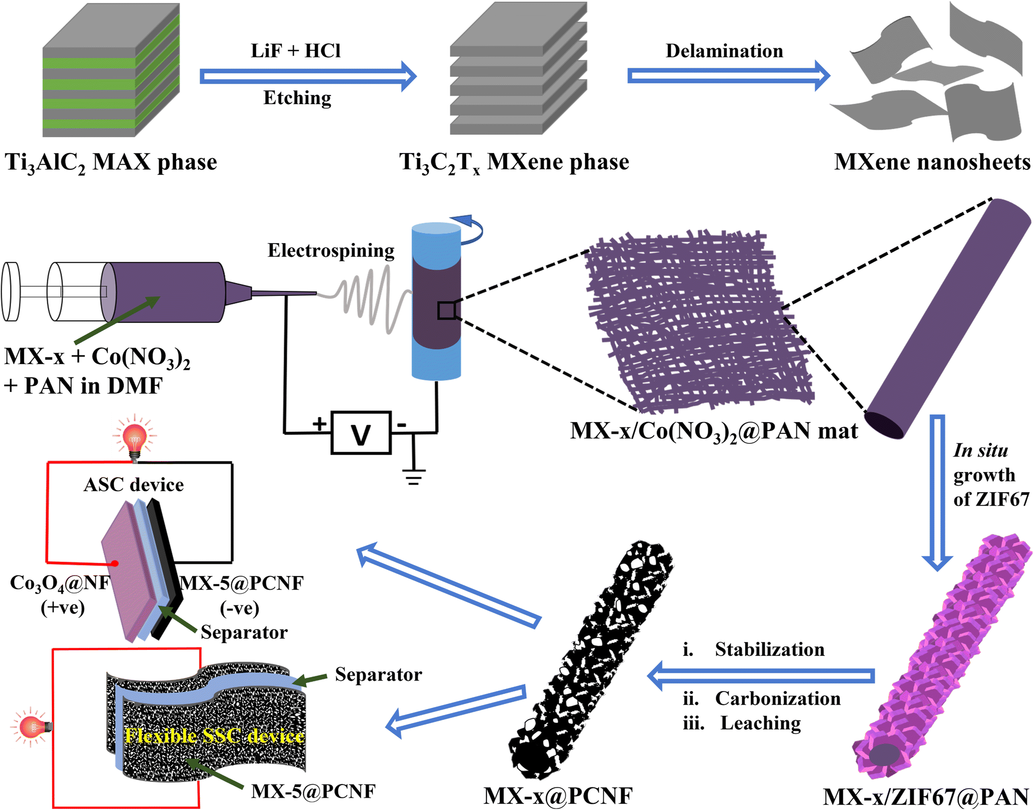 | ||
| Fig. 1 Schematic illustration of the synthesis of Ti3C2Tx MXenes, and fabrication of MX-x@PCNF electrodes, and SSC and ASC devices. | ||
The typical accordion-like morphology of MXenes (Fig. S1a†) was obtained after etching Al from the MAX phase precursor. Fig. S1b and c† show the TEM images of exfoliated ultrathin MXene nanosheets. The HR-TEM image and SAED patterns (Fig. S1d and e†) show the crystalline nature of MXenes. In the XRD patterns of MXenes (Fig. S1f†), a sharp (002) peak broadens and shifts toward a lower angle (7.05°), indicating an increase in the d-spacing and a decrease in the thickness of the MXene layers, which is convincing evidence for the selective etching of Al from the Ti3AlC2 MAX phase.37 The complete removal of the intense (104) peak at 38.8° from the XRD pattern of the MAX phase (JCPDS Card No. 98-018-2475) also confirms the removal of Al and successful preparation of MXenes. Etching phenomena are further confirmed by comparing the percentage of Al in both the Ti3AlC2 MAX phase and Ti3C2Tx MXenes through EDX analysis and elemental mapping. Fig. S2† shows a 7.58 atomic% of Al in the MAX phase, which is almost removed, and only 0.07 atomic% remains after etching, as shown in the EDX results of MXenes (Fig. S3†). Furthermore, elemental mapping spectra of Ti3C2Tx MXenes (Fig. S3†) show a high content of O and F along with Ti and C, which suggests the removal of Al and the introduction of surface terminating groups such as –O and –OH from water, and –F from HF. Fig. S4a and b† display the AFM images (2D & 3D) of an exfoliated MXene nanosheet coated over a glass substrate. The AFM height profile of the MXene nanosheet is approximately 3.308 nm (Fig. S4c†), which also indicates the successful delamination of MXenes.
The chemical compositions and electronic states of Ti3C2Tx MXene nanosheets were analyzed by XPS. The low-resolution XPS spectrum of the MXene nanosheet (Fig. S4d†) shows the presence of Ti, C, F, and O with almost complete removal of Al, which indicates the successful conversion of the Ti3AlC2 MAX phase into Ti3C2Tx MXenes. The atomic% of Ti, F, C, O, and Al present in MXenes from XPS analysis is matched with the EDX results presented in Table S1.† The high-resolution Ti 2p spectrum (Fig. S4e†) shows Ti–C bonds (455.03 eV), Ti(II) (455.80 eV), Ti(III) (456.96 eV), Ti–O (458.71 eV), and Ti–F (460.69 eV).38 In the C 1s spectrum (Fig. S4f†), peaks at 281.61 eV, 282.613 eV, 284.15 eV, and 286.29 eV correspond to C–Ti–Tx, Ti–C–O, C–C, and C–O bonds, respectively.34,38 Similarly, high-resolution O 1s spectra (Fig. S4g†) show deconvoluted peaks of Ti–O, Ti–O–C, Ti–C–(OH)x, H2O, and O–F at 528.43, eV, 530.39 eV, 531.82 eV, 533.08 eV, and 534.33 eV, respectively, revealing sufficient surface terminating functionalities in MXenes.38,39 Furthermore, the F 1s spectra (Fig. S4h†) are deconvoluted into two signature peaks of C–Ti–F (685.03 eV) and O–F (686.1 eV).34,38 Hence, the aforementioned results confirmed the successful preparation of MXenes.
The delaminated MXene nanosheets along with cobalt nitrate have been incorporated into the PAN fibers by electrospinning to investigate the effect of MXene concentration on electrode materials for supercapacitors. The detailed process of the electrospinning process is described in the Experimental section. DMF was used as a solvent for electrospinning, as MXenes are well dispersed in DMF. By using DMF as a solvent during electrospinning, the self-stacking phenomena of MXenes can also be overcome because DMF can easily intercalate between MXene sheets and hence act as a spacer.40 Zhang et al. (2021) reported that MXenes can be delaminated by shaking in DMF for a short period without the need for a sonication step.41 Hence, DMF acts as a spacer between MXene sheets as well as a solvent during electrospinning. MXene nanosheets are negatively charged due to surface terminating functional groups, which may attract Co2+ ions, resulting in the uniform distribution of cobalt salt along with MXenes in the fiber.42 The digital images of the as-spun mats containing cobalt salt and different wt% of MXenes (Fig. S5†) show that the mats become darker with increasing MXene concentration. The FESEM images (Fig. S6†) compare the morphology of each electrospun mat where the fiber diameter linearly increases with an increase in MXene concentration. The average diameter of the fiber with 1 wt% MXene (MX-1/(Co3)2@PAN) (Fig. S6a†) was observed to be ∼235 nm, which increases slightly when the MXene concentration is 2 wt% (MX-2/(Co3)2@PAN) (Fig. S6b†). At 5 wt% MXene (MX-5/(Co3)2@PAN) (Fig. S6c†), the uniformity of the fiber is still maintained, and the diameter increases to ∼300 nm. Upon further increasing the concentration of MXene to 10 wt% (MX-10/(Co3)2@PAN) (Fig. S6d†), the average fiber diameter becomes wider by ∼550 nm, and MXene sheets start to agglomerate and protrude outside the fiber, which creates some nodules and disturbs the maintenance of the uniform morphology. EDX analysis and elemental mapping of MX-5/(Co3)2@PAN (Fig. S7†) show the uniform distribution of C, Ti, N, O, Co, and F in the fiber. Similarly, Fig. S8–S10† display the EDX spectrum and elemental mapping of MX-1/(Co3)2@PAN, MX-2/(Co3)2@PAN, and MX-10/(Co3)2@PAN, respectively. The elemental compositions (from the EDX spectrum) of the fibers containing different concentrations of MXenes are tabulated (Table S2†).
The as-spun MX-5/Co(NO3)2@PAN mat (Fig. 2a) was converted to MX-5/ZIF67@PAN by the in situ growth method. The MX-5/Co(NO3)2@PAN mat was dipped in a 4% hot methanolic solution of 2-methylimidazole to grow ZIF67 on the surface of the fibers. The aging time was varied to 2, 8, 16, and 24 h to optimize the appropriate conditions for uniform growth of ZIF67 particles on the fiber surface (Fig. S11†). The size of ZIF67 is small (∼100–150 nm) and does not uniformly grow over the fiber when aging for 2 h. The dimension of ZIF67 increases with an increase in aging time from 2 h to 8 h, but some regions of the fiber remain uncovered. Uniform growth of ZIF67 is observed at 16 h of aging time, and upon increasing the time up to 24 h, we observe overgrowth and less uniformity in the MOF structures. Therefore, 16 h is considered to be the optimized nucleation time for the growth of ZIF67 in all fibers. The FESEM images of MX-5/ZIF67@PAN are displayed in Fig. 2b–d, where the uniform formation of ZIF67 is due to the homogenous distribution of the cobalt element in the fiber, which provides favorable sites for the linker (2-methylimidazole) solution.43 Electrostatic self-assembly between homogenously distributed negatively charged MXenes and Co2+ particles helps to provide a uniform nucleation site during MOF formation.44,45 XRD patterns (Fig. 3a) of MX-5/ZIF67@PAN show the presence of a characteristic (002) peak of MXenes at 6.1° and all the major consistent peaks of ZIF67. Interestingly, the (002) peak of pristine MXenes at 7.12° shifted toward a lower angle of 6.1° in MX-5/ZIF67@PAN, indicating a further increase in the d-spacing of MXene nanosheets inside the fiber. Intercalation of the PAN, solvent (DMF) and Co2+ particles in MXene sheets was attributed to this slight shift in the (002) peak of MXenes in the electrospun fiber.40 The further enlarged d-spacing of MXenes in the fiber alleviates the restacking phenomena of MXenes and provides accessible sites for ions.46 The characteristic (002) peak of MXenes is not found in the XRD pattern of ZIF67@PAN (Fig. 3a). This evidence conclusively proves the proper compositing of MXenes with ZIF67 in the fiber.
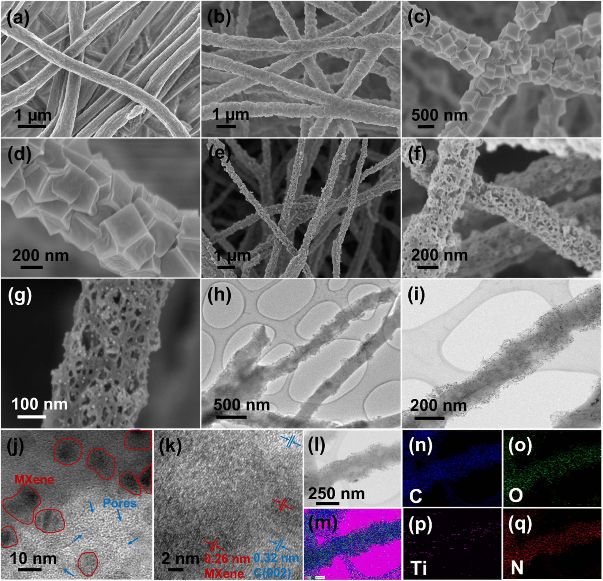 | ||
| Fig. 2 (a) FESEM image of (MX-5/Co(No3)2@PAN), (b)–(d) FESEM images of MX-5/ZIF67@PAN, (e)–(g) FESEM images of MX-5@PCNF, (h) and (i) TEM images, (j) and (k) HR-TEM images, (l) TEM image of elemental mapping area, (m) sum elemental mapping spectrum, and elemental mapping of (n) C, (o) O, (p) Ti, and (q) N. | ||
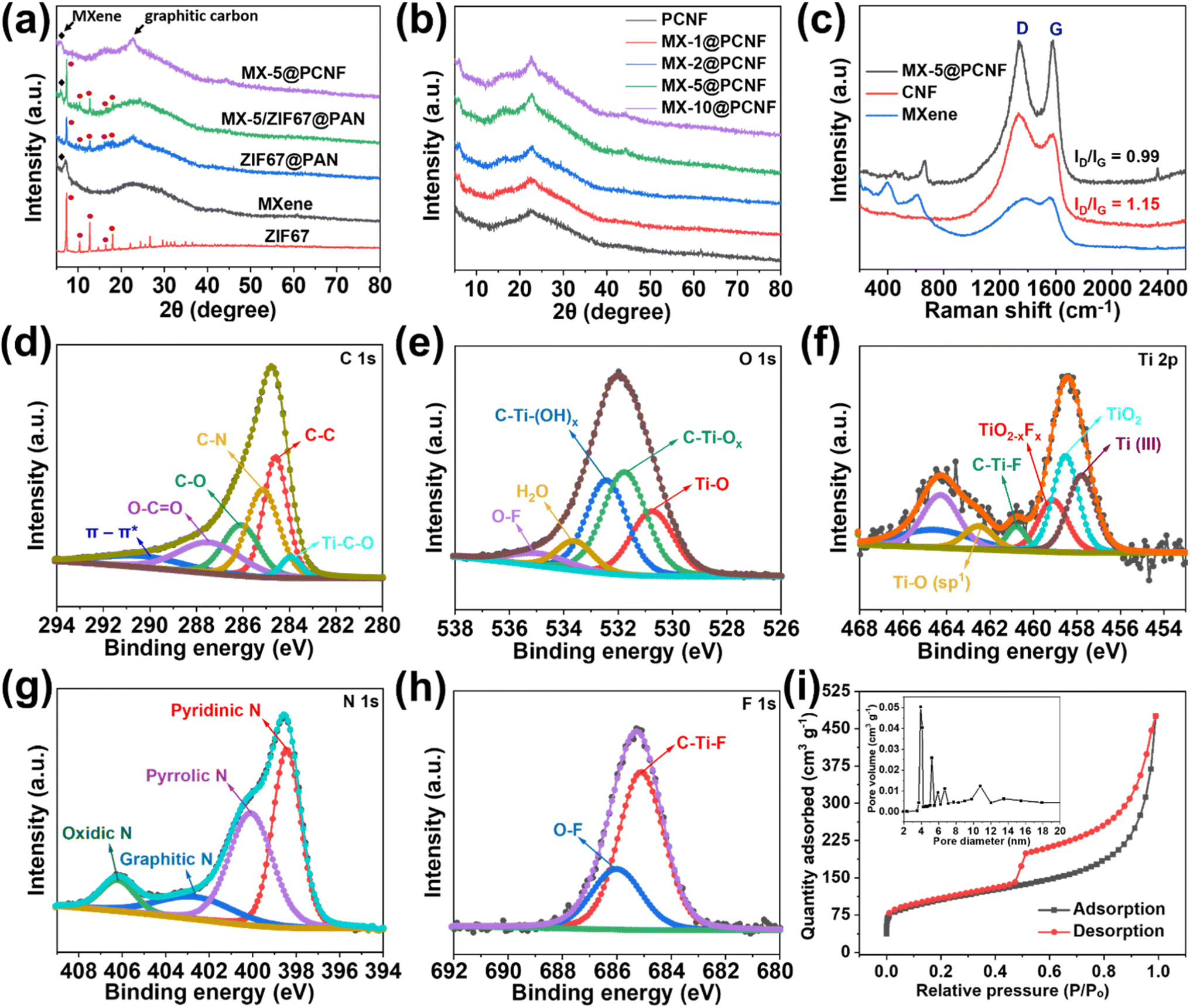 | ||
| Fig. 3 (a) XRD patterns of ZIF67, MXene, ZIF67@PAN, MX-5@ZIF67, and MX-5@PCNF. (b) XRD patterns of different samples. (c) Raman spectra. High resolution XPS spectrum of MX-5@PCNF deconvoluted for (d) C 1s, (e) O 1s, (f) Ti 2p, (g) N 1s, and (h) F 1s, and (i) BET adsorption–desorption isotherms for MX-5@PCNF (inset: pore-size distribution curve). | ||
The as-obtained MX-5/ZIF67@PAN was converted to a highly porous, flexible, and freestanding mat after subsequent stabilization, carbonization, and leaching, which was named MX-5@PCNF. Fig. 2e–g and S12a, b† display the FESEM images and optical images of the flexible MX-5@PCNF, respectively. The representative FESEM images of other control samples (PCNF, MX-1@PCNF, MX-2@PCNF, and MX-10@PCNF) are presented in Fig. S12c–f.† During carbonization, the rhombic dodecahedral ZIF67 crystals collapsed and were reduced to cobalt atoms. Metallic cobalt catalyzes the graphitization of carbon, which converts the inherently porous MOF (ZIF67 crystals) to nanoporous carbon with a higher content of sp2 hybridized carbon with high electrical conductivity.47 The residual cobalt was removed by leaching with 2 M HNO3 for 18 h, which increases the porosity and surface area and maintains the flexibility of the fiber mat. A comparison of the low-resolution XPS spectra of MX-5@PCNF before and after acid leaching (Fig. S13†) confirms the removal of Co after leaching. Fig. 2h and i display the TEM images of MX-5@PCNF. The HR-TEM image (Fig. 2j) shows the presence of a porous network along with Ti3C2Tx MXenes (indicated by red circles in the figure). The crystalline planes in HR-TEM (Fig. 2k) with lattice fringes of approximately 0.32 nm and 0.26 nm are due to the (002) plane of graphitic carbon and MXene, respectively. EDX color mapping (Fig. 2l–q) and the EDX spectrum (Fig. S14†) demonstrates the uniform distribution of Ti with C and other elements, which indicates that the Ti3C2Tx MXene flakes are homogeneously distributed in the carbon nanofiber.
In the XRD patterns of MX-5@PCNF (Fig. 3a), the broad peak at 22.7° represents the (002) plane of carbon, indicating the graphitic nature of the material, which is consistent with the previous report.17 The small peak at approximately 6.1° is attributed to the characteristic peak of MXenes in the material.35Fig. 3b compares the XRD patterns of the as-prepared materials, where the intensity of the MXene peak at 6.1° increases slightly with the increase in the weight percentage of MXenes in the fiber. The graphitic nature of carbon in XRD is further supported by Raman spectra (Fig. 3c). In each spectrum, the D band (1335 cm−1) and G band (1581 cm−1) represent disordered carbon and graphitic carbon, respectively, in the lattice structure.48 The G band in MX-5@PCNF is more intense than the G band in pristine carbon nanofibers (CNFs) carbonized at 700 °C. Furthermore, we observed that the ID/IG ratio of MX-5@PCNF (ID/IG = 0.99) is lower than the ID/IG ratio of CNF (ID/IG = 1.15), which signifies a higher degree of graphitization in MX-5@PCNF than in CNF.49 The results indicate that the MXene supports the degree of graphitization in the fiber. However, the D band in MX-5@PCNF is still intense, possibly due to some defects created by MXene sheets present in the fiber. For MXenes, the additional peak at approximately 401 cm−1 is due to oxygen atom vibrations.50 Furthermore, the peak at approximately 613 cm−1 corresponds to the Eg vibrational mode of carbon in Ti3C2Tx MXenes with the –OH functional group.50,51 The additional peak at approximately 645 cm−1 in MX-5@PCNF is due to the Eg vibrational mode of carbon in Ti3C2T(OH)x, which is evidence for proper compositing of MXenes in the resulting material.51 The slight change in the peak position is due to the strong interaction of MXenes with the PCNF.
The elemental composition and bonding states in MX-5@PCNF were studied by XPS analysis. The low-resolution XPS spectra of MX-5@PCNF provided in Fig. S13b† show the presence of C, Ti, O, F, and N. The high-resolution XPS spectra of C, O, Ti, N, and F with their respective deconvoluted peaks and peak positions are presented in Fig. 3d–h. The deconvoluted peaks of C 1s at 283.9 eV, 284.4 eV, 285.1 eV, 286.1 eV, and 287.4 eV represent Ti–C–O, C![[double bond, length as m-dash]](https://www.rsc.org/images/entities/char_e001.gif) C, C–N, C–O, and O–CO, respectively.34,52,53 The high resolution peaks of O 1s at 530.6 eV, 531.7 eV, 532.2 eV, 533.8 eV, and 534.8 eV correspond to Ti–O, C–Ti–Ox, C–Ti–(OH)x, H2O, and O–F, respectively, which implies that the surface terminating functionalities are well retained in the fiber.54 The Ti 2p peak was deconvoluted into Ti(III) (457.7 eV), TiO2 (458.5 eV), TiO2−xFx (459.1 eV), C–Ti–F (460.7 eV), and Ti–O (sp1) (462.5 eV), which are in good agreement with the literature.38,54–56 The presence of titanium peaks with reasonable intensity in MX-5@PCNF further indicates the proper coordination of MXenes in carbon nanofibers. The slight changes in the valence state and position of the deconvoluted peaks of Ti 2p in the fiber compared to that in pristine MXene is due to the interaction of MXenes with other components in the fiber. The N 1s transition is deconvoluted into four peaks at 398.4 eV, 400.1 eV, 402.6 eV, and 406.2 eV representing pyridinic, pyrrolic, graphitic, and oxidic nitrogen, respectively.57 Pyridinic and oxidic nitrogen have been reported to help increase the conductivity of the carbon network.58 Similarly, the F 1s transition is deconvoluted into two peaks at 685.1 eV and 686.0 eV assigned to C–Ti–F and O–F, respectively.34,38 The atomic% of C, Ti, O, F, and N of MX-5@PCNF is 67.72, 4.37, 12.62, 0.08, and 15.21, respectively. The overall result shows the graphitization, N doping, and proper composite of MXene in the carbon nanofiber.
C, C–N, C–O, and O–CO, respectively.34,52,53 The high resolution peaks of O 1s at 530.6 eV, 531.7 eV, 532.2 eV, 533.8 eV, and 534.8 eV correspond to Ti–O, C–Ti–Ox, C–Ti–(OH)x, H2O, and O–F, respectively, which implies that the surface terminating functionalities are well retained in the fiber.54 The Ti 2p peak was deconvoluted into Ti(III) (457.7 eV), TiO2 (458.5 eV), TiO2−xFx (459.1 eV), C–Ti–F (460.7 eV), and Ti–O (sp1) (462.5 eV), which are in good agreement with the literature.38,54–56 The presence of titanium peaks with reasonable intensity in MX-5@PCNF further indicates the proper coordination of MXenes in carbon nanofibers. The slight changes in the valence state and position of the deconvoluted peaks of Ti 2p in the fiber compared to that in pristine MXene is due to the interaction of MXenes with other components in the fiber. The N 1s transition is deconvoluted into four peaks at 398.4 eV, 400.1 eV, 402.6 eV, and 406.2 eV representing pyridinic, pyrrolic, graphitic, and oxidic nitrogen, respectively.57 Pyridinic and oxidic nitrogen have been reported to help increase the conductivity of the carbon network.58 Similarly, the F 1s transition is deconvoluted into two peaks at 685.1 eV and 686.0 eV assigned to C–Ti–F and O–F, respectively.34,38 The atomic% of C, Ti, O, F, and N of MX-5@PCNF is 67.72, 4.37, 12.62, 0.08, and 15.21, respectively. The overall result shows the graphitization, N doping, and proper composite of MXene in the carbon nanofiber.
The porous nature and texture properties of the electrode materials were investigated by performing an N2 adsorption–desorption experiment. The results of the adsorption isotherms of MX-5@PCNF (Fig. 3i) and all control samples (Fig. S15†) show that MX-5@PCNF possesses the highest BET surface area of 405.59 m2 g−1. The type-IV isotherms with an apparent hysteresis loop between adsorption–desorption curves of all samples imply the mesoporous characteristics of the electrode materials, which enables the rate of ion/electron diffusion during electrochemical tests.59 The porosity developed due to the carbonization process and removal of Co nanoparticles by leaching is attributed to the appearance of the hysteresis loop in the isotherms. Among the five samples, MX-5@PCNF exhibits the highest pore volume of 0.737 cm3 g−1 along with an average pore diameter of 4.88 nm. This is one of the important reasons for the high electrochemical performance of MX-5@PCNF. The major pore size of all samples lies in the range of 3 to 12 nm indicating the dominancy of mesopores which is an exemplary condition for the easy diffusion of hydrated K+ ions during the electrochemical test.60 The BET surface area, total pore volume, and average pore diameter of all five samples are compared in Table S3.† The variation in the pore size and pore volume of the materials is due to the different concentrations of horizontally aligned MXene flakes inside the fibers. The TGA plots presented in Fig. S16a† display the thermal response of the different samples upon heating at 10 °C per minute up to 1000 °C under a nitrogen atmosphere. The result shows that the thermal stability of the samples increases linearly with an increase in MXene concentration in the fiber.
3.2 Electrochemical performance
Motivated by the uniform and highly porous morphology, high surface area, and proper compositing of highly conductive MXenes with carbon nanofibers, we attempted to test the electrochemical performance of the fabricated electrodes for supercapacitor applications. A high surface area with sufficient mesopores and electrochemically active sites of the electrode contributes to energy storage by forming an EDLC. The alleviated restacking and intrinsic conductivity of MXenes help to enhance the charge storage capacity of the material. Larger ions from electrolytes cannot penetrate through the layers of horizontally aligned MXenes in the fiber. Under these conditions, energy is stored by electrochemical adsorption instead of intercalation. This phenomenon increases the EDLCs and the cycling stability of the electrode materials.61 Ando et al. (2020) reported that in aqueous KOH electrolyte, the intercalated cations (from the electrolyte) in the MXenes become hydrated. The hydrated ions cannot interact with surface terminating groups that form EDLCs.62 At the same time, highly graphitized nitrogen-doped sp2 carbons obtained from the pyrolysis of ZIF67 produce the majority of EDLCs with some pseudocapacitance.63 Nitrogen-doped carbons increase the hydrophilicity of carbon materials due to the presence of lone pairs of electrons in pyridinic nitrogen.64 The electron withdrawing inductive effect of nitrogen modifies the electronic environment of the nearby carbon by developing polarity. The induced polarity in the carbon material provides easy access for the ions from the aqueous electrolyte. Furthermore, the negative functionalities such as –F, –O, and –OH present in MXenes (as observed in the XPS study) enhance the hydrophilicity of the fiber which is supported by the contact angle measurement results (Fig. S16b and c†). MX-5@PCNF is found to have a contact angle of 3.65° showing better hydrophilicity than PCNF having a contact angle of 19.7°. The negative functionalities present in MXenes not only increase the hydrophilicity but also attract opposite charges from the electrolyte, facilitating the formation of an electrochemical double layer. Under these conditions, if the cations from electrolytes have a small enough size to pass through MXene layers, they may deform the electrode, and some pseudocapacitance is expected apart from the majority of EDLCs.61 Furthermore, oxygen present in the graphitic carbons also contributes to some pseudocapacitance.65 This shows that MXene-integrated nanoporous carbon has a synergistic advantages of a high surface area, sufficient active sites, hydrophilicity, and conductivity for charge storage.Before assembling the SSC and ASC devices, the electrochemical performances of the as-prepared freestanding electrodes were tested in a three-electrode system using aqueous 3 M KOH as an electrolyte. The cyclic voltammetry curve of the optimized MX-5@PCNFs (Fig. 4a) in the negative potential range of −1 to 0 V shows a nearly rectangular curve, indicating that the charge storage mechanism is primarily due to the EDLC. Upon increasing the scan rate from 5 to 100 mV s−1, the area of the CV curve increases and maintains good symmetry even at a high scan rate of 100 mV s−1, indicating the reversible kinetics and structural stability of the electrode material. To further analyze whether the charge storage mechanism is diffusion-controlled or surface-controlled, a linear plot of log(i) vs. log(ν) for MX-5@PCNF was plotted (Fig. S17a†) using the power law eqn (1) and (2):
| i = aνb | (1) |
| log(i) = blog(ν) + log(a) | (2) |
| i(V) = k1ν + k2ν1/2 | (3) |
000 continuous charge/discharge cycles at 2 A g−1 (Fig. 4e). MX-5@PCNFs has 96.4% capacitance retention, which is the highest among all five samples. As displayed in Fig. 4f, the GCD curves of MX-5@PCNF before and after the cycling stability test at 2 A g−1 show no obvious change in the nature of the curve and the discharge time. The formation of an electrical double layer at the electrode–electrolyte interface by the adsorption–desorption phenomenon is attributed to the high cycling stability. Oxygen, nitrogen, and surface terminating groups of MXenes present in the fiber also boost the performance by contributing a small pseudocapacitance, and hence the morphology is retained. The robust stability of the electrode material is further supported by post-electrochemical characterization studies. The FESEM images of MX-5@PCNF and control electrodes after the electrochemical test (Fig. S19†) show a conserved morphology with no obvious deformations. EDX analysis (Fig. S20†) reveals a similar elemental distribution before and after the electrochemical tests except for the one extra peak of K due to K+ intercalation from the KOH electrolyte during electrochemical tests. XRD patterns before and after the stability test (Fig. S21a†) are almost consistent with each other. The nominal decrease in peak intensity after the stability test is due to a minute change in electrode material by ceaseless diffusion of OH− at the electrode electrolyte interface.49 Raman spectra before and after the stability test (Fig. S21b†) further endorse the stable nature of the electrode material.
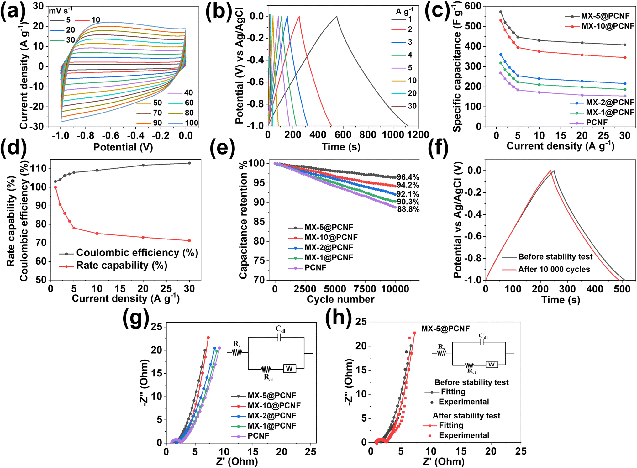 | ||
| Fig. 4 Electrochemical characterizations of MX-5@PCNF. (a) CV curves at different scan rates, (b) GCD curves at different current densities, (c) specific capacitances vs. current density curves for different samples, (d) rate capability and coulombic efficiency at different current densities, (e) cycling stability performance of different samples, (f) GCD curves at 1 A g−1 before and after the stability test, (g) EIS Nyquist plots of different samples (inset: equivalent circuit diagram of the Nyquist plot fitting), and (h) EIS Nyquist plots of MX-5@PCNF before and after the stability test (inset: equivalent circuit diagram). | ||
Apart from CV and GCD, further electrochemical behaviors of the electrode materials were studied by EIS, and the results are presented in the form of Nyquist plots. Nyquist plots explore the relationship between the electrochemical performance and resistance behavior of the materials by measuring the intrinsic resistance (Rs), charge transfer resistance (Rct), and Warburg diffusion resistance (Rw).67Rs measures the resistance of the electrolyte, resistance of electrode materials, and interfacial contact resistance. The semicircle diameter in the high-frequency zone indicates the Rct of the system, which signifies conductivity and charge transfer of the electrochemical system.60 Nyquist plots of all the electrode/electrolyte systems (Fig. 4g) displayed almost similar Rs values. MX-5@PCNF possesses a smaller semicircle with the lowest Rct value (0.71 Ω), indicating high conductivity and good charge transfer kinetics, and PCNF exhibited the highest Rct value (1.58 Ω) among all samples. The better electronic conductivity and capacitive behavior of MX-5@PCNF are further confirmed by the nearly vertical straight line of MX-5@PCNF among all five electrodes in the low-frequency region. The Rs, Rct, and Rw values of MX-5@PCNF and other samples are presented in Table S4.† Note that a comparison of the Nyquist plots of MX-5@PCNF before and after electrochemical tests (Fig. 4h) displayed a slight increase in Rct; however, Rs and Rw remained almost constant after the stability test. These results suggest high conductivity and charge transfer kinetics of the MXene integrated electrode material in the system.
The practical application of MX-5@PCNF was studied first by assembling a flexible symmetric supercapacitor device (MX-5@PCNF//MX-5@PCNF) and the relevant electrochemical results are presented in Fig. 5. As expected, the assembled symmetric device predominated the EDLC nature of the charge storage mechanism, which is illustrated by the CV and GCD curves. Fig. 5a shows the CV curve recorded in different potential windows from 0 to 0.5 V to 0 to 1.0 V while maintaining a constant scan rate of 50 mV s−1. Consistent overlapping of the similar nature of the curves in the 0.5 to 1.0 V potential window and no serious oxygen evolution reaction at higher potential shows that the device delivers excellent capacitive behavior up to a 1.0 V working potential. Fig. 5b shows the CV curves of the SSC device at different scan rates from 5 to 100 mV s−1 in a fixed potential window (0 to 1.0 V). The area of the CV curves increases with an increase in the scan rate, maintaining good symmetry even at high scan rates, further demonstrating the excellent capacitive storage and reversible ability of the device.Fig. 5c shows the GCD curves ranging from 0.5 to 1.0 V at a constant current density of 1 A g−1, showing excellent overlap with exemplary coulombic efficiency. Based on the GCD curves (Fig. 5d), the Cs of the SSC device was calculated at different current densities from 1 to 30 Ag−1. The device exhibited Cs values of 162.22, 147.05, 137.98, 131.2, 122.65, 120.0, 115.5, and 111.3 F g−1 at current densities of 1, 2, 3, 4, 5, 10, 20, and 30 A g−1, respectively, as shown in Fig. 5e. Fig. 5f shows the rate capability and coulombic efficiency of the device measured at different current densities ranging from 1 to 30 A g−1. Significantly, the device maintained a 68.61% rate capability even at a high current density of 30 A g−1. Furthermore, the coulombic efficiency at 1 A g−1 is 90.65%, which increases with an increase in current density, illustrating the practical applicability of the device. The specific capacitance, rate capability, and coulombic efficiency of the device are further summarized as a bar diagram in a single figure (Fig. 5g). The SSC device shows long cycling stability with 91.3% capacitance retention after 10000 GCD cycles at 4 A g−1 (Fig. 5h). Accordingly, the GCD curves measured at 4 A g−1 before and after the stability test (inset of Fig. 5h) show an almost coinciding curve with a negligible decrease in the discharge time and a minute increase in the potential drop. The high stability is due to the synergistic effect of conductive MXenes and highly porous carbon from MOFs at the 2D fiber with a high aspect ratio, as mentioned above. Furthermore, the flexibility of the SSC device was studied by recording the CV and GCD curves at different bending angles (60° and 90°), and twisting conditions (Fig. S22a–d†). Notably, all the CV and GCD curves (Fig. S22e and f†) almost coincide with each other at different bending angles and twisting conditions demonstrating the remarkable flexibility of the SSC device.
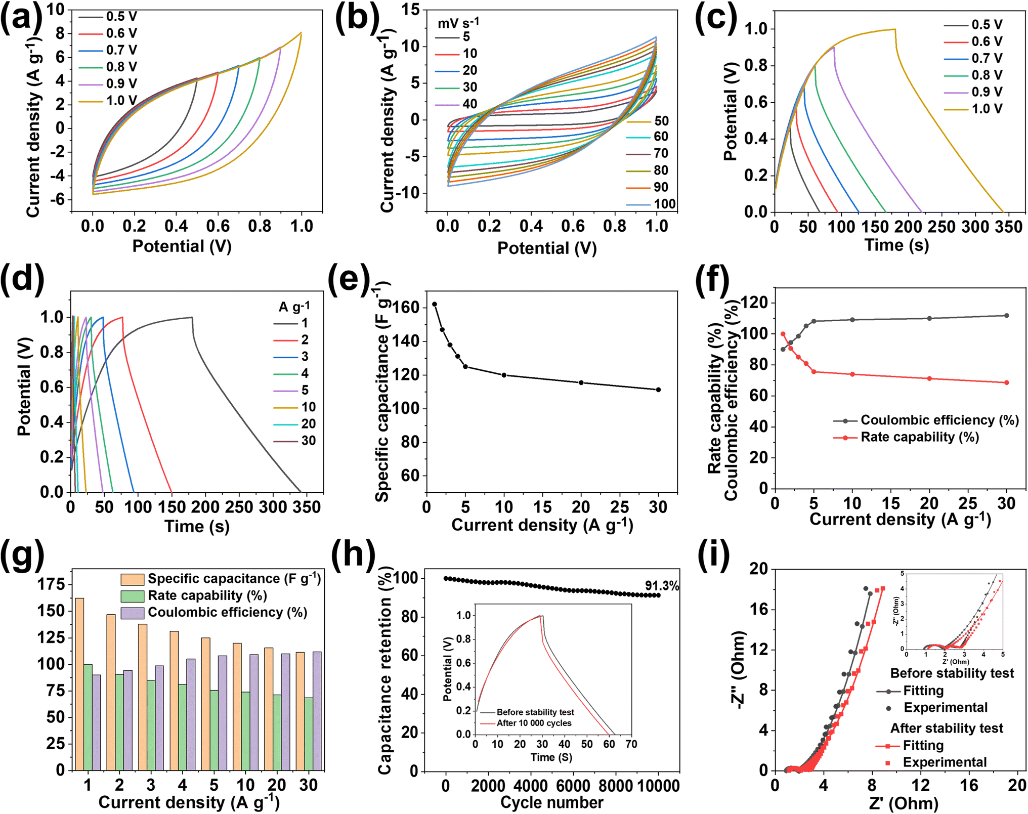 | ||
| Fig. 5 Electrochemical performance of the MX-5@PCNF//MX-5@PCNF SSC device. (a) CV curves in different voltage windows at a scan rate of 50 mV s−1, (b) CV curves at different scan rates, (c) GCD curves in different voltage windows at 1 A g−1, (d) GCD curves at different current densities, (e) specific capacitance at different current densities, (f) coulombic efficiency and rate capability at different current densities, (g) plots showing specific capacitance, rate capability and coulombic efficiency at different current densities, (h) cycling stability test (inset: GCD curves at 4 A g−1 before and after the stability test), and (i) Nyquist plot of the SSC device before and after the stability test (inset: magnified section). | ||
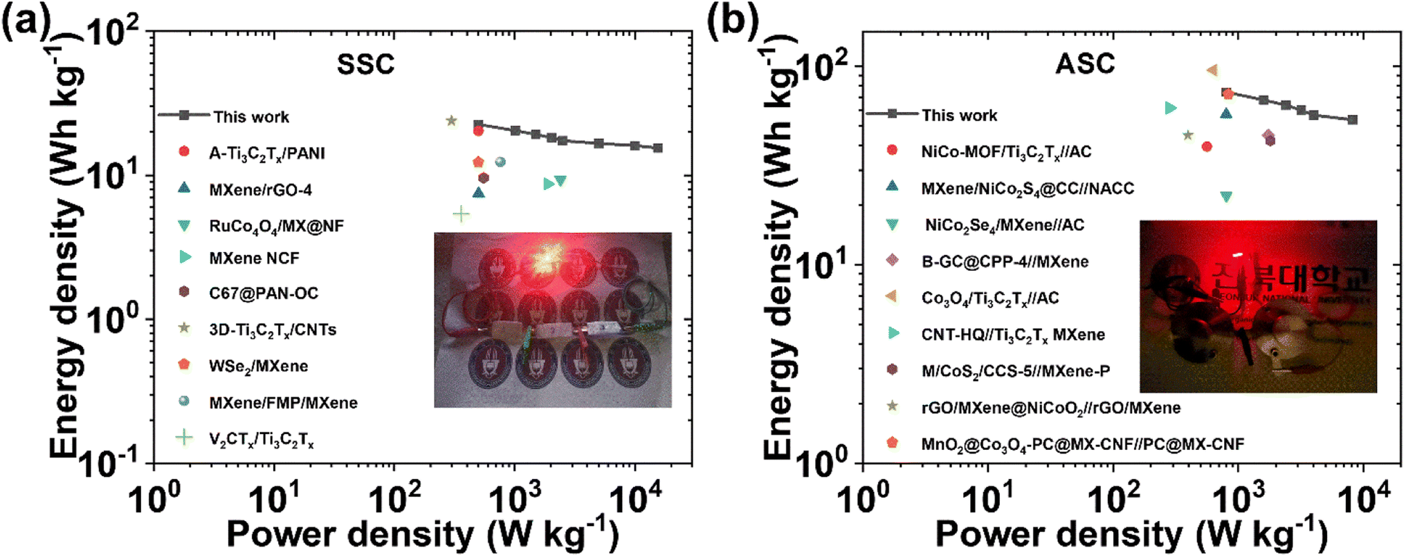
Moreover, the stable and high performance of the SSC device is further supported by EIS measured before and after 10000 charge–discharge cycles (Fig. 5i). After the stability test, the Rs value increases from 0.91 Ω to 1.11 Ω, and Rct & Rw values remain almost constant, indicating the excellent stability of the device. The equivalent series resistance (ESR) value of 1.85 Ω before the stability test increases slightly up to 2.07 Ω after the stability test. Nyquist impedance parameters, including Rs, Rct, and Rw, along with ESR values of the device before and after the stability test are presented in Table S5† for comparison. The energy density (E) and power density (P) of the SSC device were calculated using eqn (S3) and (S4),† respectively. The device delivers a maximum E of 22.53 W h kg−1 at a P of 499.99 W kg−1, and the device still maintains an E value of 15.46 W h kg−1, even at a high P value of 15587.9 W kg−1, as shown in the Ragone plot (Fig. 7a). The results show that the performance of the as-assembled SSC device is comparable to that of other recently reported MXene-based SSC devices (Table S8†). Furthermore, to demonstrate the practical applicability, three symmetric devices were connected in series to obtain a working potential of 3.0 V (Fig. S23a and b†) that powered a 1 W red light-emitting diode (LED) for 10 min (Fig. 7a, inset). 1000 continuous charge–discharge GCD cycles (at 5 A g−1) of the three devices in series were further performed in a voltage window of 0 to 3.0 V, and the results are presented in Fig. S23c and d,† showing the first and last ten cycles of the stability test of the devices. More interestingly, the red LED is again powered for ∼9 minutes (Fig. S23e†) by the devices after a 1000 cycles of the stability test. Hence, these fascinating electrochemical results and successful practical application of the as-assembled SSC device suggest the potential application of freestanding MX-5@PCNF for next-generation flexible energy storage devices.
 | ||
| Fig. 6 Electrochemical performance of the Co3O4@NF//MX-5@PCNF ASC device. (a) CV curves in different voltage windows at a scan rate of 50 mV s−1, (b) CV curves at a scan rate of 5 to 100 mV s−1, (c) GCD curves at different current densities, (d) specific capacitance at different current densities, (e) cycling stability test (inset: GCD curves at 1 A g−1 before and after the stability test), and (f) Nyquist plot of the ASC device before and after the stability test (inset: magnified section in the high-frequency region). | ||
 | ||
| Fig. 7 Ragone plots of the devices compared with those in reported studies in the literature: the (a) MX-5@PCNF//MX-5@PCNF SSC device (inset: red LED powered by three SSC devices connected in series), and (b) Co3O4/NF//MX-5@PCNF ASC device (inset: red LED powered by two ASC devices). | ||
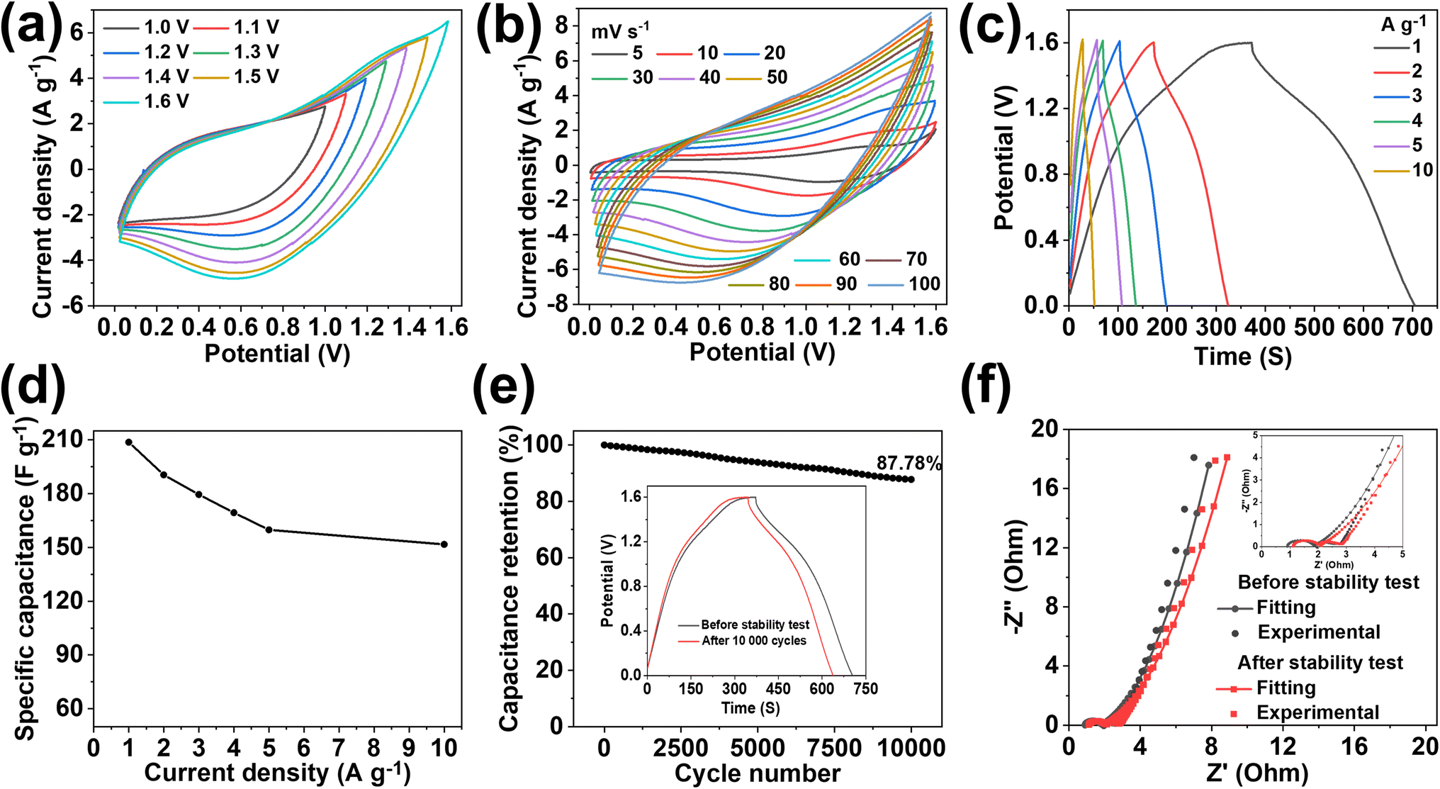
Given the excellent electrochemical performance of MX-5@PCNF in the three-electrode system and SSC device, we assembled an ASC device by using MX-5@PCNF as a negative electrode. The frequently studied and commonly used Co3O4 on nickel foam was used as a positive electrode. The detailed procedure for the synthesis of the positive electrode is mentioned in the Experimental section, ESI.† In our previous studies, Co3O4 nanohairs were extensively studied and used during the fabrication of ASC devices.12,16,68,69 Therefore, detailed morphological and electrochemical characterization studies of this pseudocapacitive positive electrode are not included here. Fig. S24a–d† display the FESEM images of Co3O4 nanohairs over nanosheets on nickel foam and the XRD patterns of the Co3O4 powder. The CV and GCD plots of Co3O4@NF are presented in Fig. S24e and f.† Based on the GCD curves, Co3O4@NF delivered a Cs as high as 1891 F g−1 at 1 A g−1. A detailed calculation for the mass balancing of the positive and negative electrodes during ASC device fabrication is presented in the ESI.†
To optimize the working potential for the fabricated ASC device (Co3O4@NF//MX-5@PCNF), CV curves were obtained in different voltage windows from 1.0 to 1.6 V at 50 mV s−1 (Fig. 6a). The consistent overlapping of the CV curves shows that the device can work properly in a voltage window up to 1.6 V. The combined CV curves of the negative and positive electrodes in a three-electrode system (Fig. S25a†) further illustrate the extension of the working potential of the ASC device up to 1.6 V. Fig. 6b displays the CV curves of the device measured at different scan rates from 5 to 100 mV s−1 between 0 and 1.6 V. The shape of the CV curve is retained even at a high scan rate of 100 mV s−1, indicating the high electrochemical performance of the device. The GCD curves at different current densities ranging from 1 to 10 A g−1 (Fig. 6c) show the almost symmetrical nature of the curves, which are retained even up to a high current density of 10 A g−1, demonstrating the excellent electrochemical performance with high reversibility. The calculated Cs values of the device were 208.7, 190.5, 179.5, 169.4, 159.8, and 151.7 F g−1 at current densities of 1, 2, 3, 4, 5, and 10 A g−1, respectively. The decrease in specific capacitance with an increase in current density is due to the incomplete faradaic reaction and increase in intrinsic resistance of the electrode at high current density.70
The device maintained 72.68% of its initial capacitance even with a 10-fold increase in current density, and the coulombic efficiency increased from 88.35% at 1 A g−1 to ∼100% at 10 A g−1 (Fig. S25b†). These fascinating results show the excellent rate capability and capacitive properties of the ASC device. In addition, durable cycling stability is one of the important performance metrics for the practical application of devices in long-term use. As shown in Fig. 6e, the ASC device retains 87.78% of its initial capacitance after 10000 continuous charge–discharge cycles at a current density of 5 A g−1. The excellent stability of the device is also supported by the almost symmetrical GCD curve with a comparable discharge time at 1 A g−1 before and after the stability test (Fig. 6e, inset). The Nyquist impedance parameters of the device were further checked before and after 10000 cycles (Fig. 6f), which showed marginal increases in Rs, Rct, and Rw values and hence, the ESR values. Table S6† compares the Nyquist impedance parameters of the ASC device before and after the stability test. The Ragone plot (Fig. 7b) shows that the ASC device could deliver a high E of 74.2 W h kg−1 at a P of 800 W kg−1 at 1 A g−1, and the device still maintained an E of 53.9 W h kg−1 with an increase in P to 8222 W kg−1 at 10 A g−1. Notably, these values are competitive with the results of recently published ASC devices using MXene-based electrode materials (Table S9†). Furthermore, two ASC devices were connected in series that could power a 1 W red LED for ∼10 minutes after charging at 10 A g−1 (Fig. 7b, inset), demonstrating the practical applicability of the as-assembled ASC device.
4. Conclusions
In summary, we have developed binder-free, freestanding, and flexible MXene-incorporated MOF-based porous carbon nanofiber electrodes with improved electrochemical performance. To engineer the electrode, an optimized sequential strategy was applied. First, we synthesized MXenes by the MILD method and incorporated MXene nanosheets in PAN fibers at different concentrations by the facile electrospinning technique. ZIF67 was prepared by an in situ method and eventually converted to highly porous flexible/freestanding nanofibers after sequential stabilization, carbonization, and acid leaching. The as-prepared materials were used as freestanding electrodes for supercapacitors without any binders and the effect of MXene concentration in the fiber was investigated. MX-5@PCNF achieved a high Cs of 572.7 F g−1 at 1 A g−1 with good rate capability (71.24% at 30 A g−1), high cycling stability (96.4% capacitance retention after 10000 cycles at 2 A g−1), and ideal coulombic efficiency relative to other counter electrodes. The optimized MX-5@PCNF was used to construct SSC device in a sandwich configuration using 3 M KOH electrolyte. The SSC device exhibited good flexibility and delivered an efficient E of 22.53 W h kg−1 at a P of 499.99 W kg−1 along with excellent cycling stability, and high rate capability and coulombic efficiency. The ASC device (Co3O4@NF//MX-5@PCNF) was also fabricated, which furnished a maximum E of 74.2 W h kg−1 at a P of 800 W kg−1 with superior cycling performance (capacitance retention of 87.78% after 10000 cycles at 5 A g−1). Overall, this work offers a new approach to design MXene integrated PCNF freestanding electrodes with enhanced performance for flexible supercapacitors, and the technique can be adapted to other members of the MXene family.
Author contributions
Ishwor Pathak: conceptualization, methodology, investigation, data curation, writing-original draft, writing-review & editing. Debendra Acharya: data curation, formal analysis. Kisan Chhetri: investigation, formal analysis. Prakash Chandra Lohani: software, data curation. Subhangi Subedi: formal analysis, visualization. Alagan Muthurasu: data curation, formal analysis. Taewoo Kim: formal analysis, visualization. Tae Hoon Ko: formal analysis, project administration. Bipeen Dahal: conceptualization, methodology, supervision, formal analysis. Hak Yong Kim: conceptualization, supervision, funding acquisition, resources.Conflicts of interest
There are no conflicts to declare.Acknowledgements
The authors are thankful to the National Research Foundation (NRF) of Korea, Korean government (MSIT) (project numbers 2020R1I1A1A01073937 and 2022R1A2C2007676) for funding the grant.References
- T. Ma, Y. Pan, J. Chen, Z. Yan, B. Chen, L. Zhao, L. Hu, L. Wen and M. Hu, J. Mater. Chem. A, 2022, 10, 9932–9940 RSC
.
- M. R. Kandel, U. N. Pan, D. R. Paudel, P. P. Dhakal, N. H. Kim and J. H. Lee, Composites, Part B, 2022, 239, 109992 CrossRef CAS
- P. P. Dhakal, U. N. Pan, D. R. Paudel, M. R. Kandel, N. H. Kim and J. H. Lee, Mater. Today Nano, 2022, 20, 100272 CrossRef CAS
- Q. Li, Q. Zhang, Z. Zhou, W. Gong, C. Liu, Y. Feng, G. Hong and Y. Yao, Nano Res., 2021, 14, 91–99 CrossRef CAS
- S. Sahoo, R. Kumar, E. Joanni, R. K. Singh and J.-J. Shim, J. Mater. Chem. A, 2022, 10, 13190–13240 RSC
- Q. Li, S. Jing, Z. Yong, Q. Zhang, C. Liu, K. Zhu, Y. Feng, W. Gong and Y. Yao, Energy Storage Mater., 2021, 42, 815–825 CrossRef
- X. Liu, Y. Sun, Y. Tong, X. Wang, J. Zheng, Y. Wu, H. Li, L. Niu and Y. Hou, Nano Energy, 2021, 86, 106070 CrossRef CAS
- W. Cheng, J. Fu, H. Hu and D. Ho, Adv. Sci., 2021, 8, 2100775 CrossRef CAS PubMed
- M. B. Poudel and H. J. Kim, J. Energy Chem., 2022, 64, 475–484 CrossRef CAS
- D. Acharya, I. Pathak, B. Dahal, P. C. Lohani, R. M. Bhattarai, A. Muthurasu, T. Kim, T. H. Ko, K. Chhetri and H. Y. Kim, Carbon, 2023, 201, 12–23 CrossRef CAS
- J. Acharya, G. P. Ojha, B. Pant and M. Park, J. Mater. Chem. A, 2021, 9, 23977–23993 RSC
- B. Dahal, T. Mukhiya, G. P. Ojha, K. Chhetri, A. P. Tiwari, A. Muthurasu, M. Lee, S.-H. Chae, T. Kim, D. C. Chung and H. Y. Kim, Chem. Eng. J., 2020, 387, 124028 CrossRef CAS
- K. Chhetri, B. Dahal, A. P. Tiwari, T. Mukhiya, A. Muthurasu, G. P. Ojha, M. Lee, T. Kim, S.-H. Chae and H. Y. Kim, ACS Appl. Energy Mater., 2021, 4, 404–415 CrossRef CAS
- Q. Li, Small, 2021, 17, 2101617 CrossRef CAS PubMed
- M. Kim, C. Wang, J. Earnshaw, T. Park, N. Amirilian, A. Ashok, J. Na, M. Han, A. E. Rowan, J. Li, J. W. Yi and Y. Yamauchi, J. Mater. Chem. A, 2022, 10, 24056–24063 RSC
- K. Chhetri, A. P. Tiwari, B. Dahal, G. P. Ojha, T. Mukhiya, M. Lee, T. Kim, S.-H. Chae, A. Muthurasu and H. Y. Kim, J. Electroanal. Chem., 2020, 856, 113670 CrossRef CAS
- B. Dahal, T. Mukhiya, G. P. Ojha, A. Muthurasu, S.-H. Chae, T. Kim, D. Kang and H. Y. Kim, Electrochim. Acta, 2019, 301, 209–219 CrossRef CAS
- G. Dhakal, D. Mohapatra, Y.-I. Kim, J. Lee, W. K. Kim and J.-J. Shim, Renewable Energy, 2022, 189, 587–600 CrossRef CAS
- P. C. Lohani, A. P. Tiwari, K. Chhetri, A. Muthurasu, B. Dahal, S.-H. Chae, T. H. Ko, J. Y. Lee, Y. S. Chung and H. Y. Kim, ACS Appl. Mater. Interfaces, 2022, 14, 23285–23296 CrossRef CAS PubMed
- G. P. Ojha, B. Pant, J. Acharya and M. Park, Nanoscale, 2021, 13, 19537–19548 RSC
- C. Ma, M.-G. Ma, C. Si, X.-X. Ji and P. Wan, Adv. Funct. Mater., 2021, 31, 2009524 CrossRef CAS
- K. Nasrin, V. Sudharshan, K. Subramani and M. Sathish, Adv. Funct. Mater., 2022, 32, 2110267 CrossRef CAS
- L. Jiang, D. Zhou, J. Yang, S. Zhou, H. Wang, X. Yuan, J. Liang, X. Li, Y. Chen and H. Li, J. Mater. Chem. A, 2022, 10, 13651–13672 RSC
- J. Azadmanjiri, T. N. Reddy, B. Khezri, L. Děkanovský, A. K. Parameswaran, B. Pal, S. Ashtiani, S. Wei and Z. Sofer, J. Mater. Chem. A, 2022, 10, 4533–4557 RSC
- R. Zhang, J. Dong, W. Zhang, L. Ma, Z. Jiang, J. Wang and Y. Huang, Nano Energy, 2022, 91, 106633 CrossRef CAS
- Q. Zhu, J. Li, P. Simon and B. Xu, Energy Storage Mater., 2021, 35, 630–660 CrossRef
- M. Boota and Y. Gogotsi, Adv. Energy Mater., 2019, 9, 1802917 CrossRef
- K. Li, X. Wang, X. Wang, M. Liang, V. Nicolosi, Y. Xu and Y. Gogotsi, Nano Energy, 2020, 75, 104971 CrossRef CAS
- L. Wang, D. Shao, J. Guo, S. Zhang and Y. Lu, Energy Technol., 2020, 8, 1901003 CrossRef CAS
- Y.-L. Huang and S.-W. Bian, J. Mater. Chem. A, 2021, 9, 21347–21356 RSC
- R. Ma, Z. Chen, D. Zhao, X. Zhang, J. Zhuo, Y. Yin, X. Wang, G. Yang and F. Yi, J. Mater. Chem. A, 2021, 9, 11501–11529 RSC
- B. Joshi, E. Samuel, Y.-i. Kim, A. L. Yarin, M. T. Swihart and S. S. Yoon, Coord. Chem. Rev., 2022, 460, 214466 CrossRef CAS
- A. S. Levitt, M. Alhabeb, C. B. Hatter, A. Sarycheva, G. Dion and Y. Gogotsi, J. Mater. Chem. A, 2019, 7, 269–277 RSC
- H. Hwang, S. Byun, S. Yuk, S. Kim, S. H. Song and D. Lee, Appl. Surf. Sci., 2021, 556, 149710 CrossRef CAS
- K. Yang, M. Luo, D. Zhang, C. Liu, Z. Li, L. Wang, W. Chen and X. Zhou, Chem. Eng. J., 2022, 427, 132002 CrossRef CAS
- M. Alhabeb, K. Maleski, B. Anasori, P. Lelyukh, L. Clark, S. Sin and Y. Gogotsi, Chem. Mater., 2017, 29, 7633–7644 CrossRef CAS
- Y. Tian, Y. An, C. Wei, B. Xi, S. Xiong, J. Feng and Y. Qian, ACS Nano, 2019, 13, 11676–11685 CrossRef CAS PubMed
- Z. Wang, Z. Xu, H. Huang, X. Chu, Y. Xie, D. Xiong, C. Yan, H. Zhao, H. Zhang and W. Yang, ACS Nano, 2020, 14, 4916–4924 CrossRef CAS PubMed
- M. Yao, Y. Chen, Z. Wang, C. Shao, J. Dong, Q. Zhang, L. Zhang and X. Zhao, Chem. Eng. J., 2020, 395, 124057 CrossRef CAS
- J. Tang, X. Huang, T. Qiu, X. Peng, T. Wu, L. Wang, B. Luo and L. Wang, Chem.–Eur. J., 2021, 27, 1921–1940 CrossRef CAS PubMed
- Q. Zhang, H. Lai, R. Fan, P. Ji, X. Fu and H. Li, ACS Nano, 2021, 15, 5249–5262 CrossRef CAS PubMed
- X. Gao, Z.-K. Li, J. Xue, Y. Qian, L.-Z. Zhang, J. Caro and H. Wang, J. Membr. Sci., 2019, 586, 162–169 CrossRef CAS
- H. Wu, M. Almalki, X. Xu, Y. Lei, F. Ming, A. Mallick, V. Roddatis, S. Lopatin, O. Shekhah, M. Eddaoudi and H. N. Alshareef, J. Am. Chem. Soc., 2019, 141, 20037–20042 CrossRef CAS PubMed
- X. Han, Y. Huang, L. Ding, Y. Song, T. Li and P. Liu, ACS Appl. Nano Mater., 2021, 4, 691–701 CrossRef CAS
- H. Zhang, Z. Li, Z. Hou, H. Mei, Y. Feng, B. Xu and D. Sun, Chem. Eng. J., 2021, 425, 130602 CrossRef CAS
- R. Ma, X. Zhang, J. Zhuo, L. Cao, Y. Song, Y. Yin, X. Wang, G. Yang and F. Yi, ACS Nano, 2022, 15, 9713–9727 CrossRef PubMed
- Y. Yi, W. Zhao, Z. Zeng, C. Wei, C. Lu, Y. Shao, W. Guo, S. Dou and J. Sun, Small, 2020, 16, 1906566 CrossRef CAS PubMed
- Q. Deng, X.-Y. HuangYang, X. Zhang, Z.-H. Xiao, W.-B. Zhou, H.-R. Wang, H.-Y. Liu, F. Zhang, C.-Z. Li, X.-W. Wu and Y.-G. Guo, Adv. Energy Mater., 2022, 12, 2103186 CrossRef CAS
- K. Chhetri, T. Kim, D. Acharya, A. Muthurasu, B. Dahal, R. M. Bhattarai, P. C. Lohani, I. Pathak, S. Ji, T. H. Ko and H. Y. Kim, Chem. Eng. J., 2022, 450, 138363 CrossRef CAS
- S. Kumar, M. A. Rehman, S. Lee, M. Kim, H. Hong, J.-Y. Park and Y. Seo, Sci. Rep., 2021, 11, 649 CrossRef CAS PubMed
- R. Kang, Z. Zhang, L. Guo, J. Cui, Y. Chen, X. Hou, B. Wang, C.-T. Lin, N. Jiang and J. Yu, Sci. Rep., 2019, 9, 9135 CrossRef PubMed
- R. R. Salunkhe, J. Tang, Y. Kamachi, T. Nakato, J. H. Kim and Y. Yamauchi, ACS Nano, 2015, 9, 6288–6296 CrossRef CAS PubMed
- M. C. Biesinger, Appl. Surf. Sci., 2022, 597, 153681 CrossRef CAS
- J. Halim, K. M. Cook, M. Naguib, P. Eklund, Y. Gogotsi, J. Rosen and M. W. Barsoum, Appl. Surf. Sci., 2016, 362, 406–417 CrossRef CAS
- A. Pazniak, P. Bazhin, N. Shplis, E. Kolesnikov, I. Shchetinin, A. Komissarov, J. Polcak, A. Stolin and D. Kuznetsov, Mater. Des., 2019, 183, 108143 CrossRef CAS
- H. Guo, J. Zhang, M. Xu, M. Wang, F. Yang, N. Wu, T. Zhang, L. Sun and W. Yang, J. Alloys Compd., 2021, 888, 161250 CrossRef CAS
- T. Mukhiya, A. P. Tiwari, K. Chhetri, T. Kim, B. Dahal, A. Muthurasu and H. Y. Kim, Chem. Eng. J., 2021, 420, 129679 CrossRef CAS
- J. Chen, Y. Lin, J. Liu, D. Wu, X. Bai, D. Chen and H. Li, J. Energy Storage, 2021, 39, 102640 CrossRef
- Y. Li, G. Zhu, H. Huang, M. Xu, T. Lu and L. Pan, J. Mater. Chem. A, 2019, 7, 9040–9050 RSC
- B. Dahal, K. Chhetri, A. Muthurasu, T. Mukhiya, A. P. Tiwari, J. Gautam, J. Y. Lee, D. C. Chung and H. Y. Kim, Adv. Energy Mater., 2021, 11, 2002961 CrossRef CAS
- X. Zang, J. Wang, Y. Qin, T. Wang, C. He, Q. Shao, H. Zhu and N. Cao, Nano-Micro Lett., 2020, 12, 77 CrossRef CAS PubMed
- Y. Ando, M. Okubo, A. Yamada and M. Otani, Adv. Funct. Mater., 2020, 30, 2000820 CrossRef CAS
- C. Ye and L. Xu, Composites, Part B, 2021, 225, 109256 CrossRef CAS
- T. Lin, I.-W. Chen, F. Liu, C. Yang, H. Bi, F. Xu and F. Huang, Science, 2015, 350, 1508–1513 CrossRef CAS PubMed
- T. Kim, S. Subedi, B. Dahal, K. Chhetri, T. Mukhiya, A. Muthurasu, J. Gautam, P. C. Lohani, D. Acharya, I. Pathak, S.-H. Chae, T. H. Ko and H. Y. Kim, Adv. Sci., 2022, 9, 2200650 CrossRef CAS PubMed
- Q. Li, Q. Zhang, J. Sun, C. Liu, J. Guo, B. He, Z. Zhou, P. Man, C. Li, L. Xie and Y. Yao, Adv. Sci., 2019, 6, 1801379 CrossRef PubMed
- Q. Li, Q. Zhang, C. Liu, W. Gong, Z. Zhou, P. Man, J. Guo, B. He, K. Zhang, W. Lu and Y. Yao, Energy Storage Mater., 2020, 27, 316–326 CrossRef
- T. Mukhiya, B. Dahal, G. P. Ojha, K. Chhetri, M. Lee, T. Kim, S.-H. Chae, A. P. Tiwari, A. Muthurasu and H. Y. Kim, Composites, Part B, 2019, 178, 107482 CrossRef CAS
- T. Mukhiya, G. P. Ojha, B. Dahal, T. Kim, K. Chhetri, M. Lee, S.-H. Chae, A. Muthurasu, A. P. Tiwari and H. Y. Kim, ACS Appl. Energy Mater., 2020, 3, 3435–3444 CrossRef CAS
- K. Li, B. Zhao, H. Zhang, H. Lv, J. Bai, H. Ma, P. Wang, W. Li, J. Si, X. Zhu and Y. Sun, Adv. Funct. Mater., 2021, 31, 2103073 CrossRef CAS
Footnote |
| † Electronic supplementary information (ESI) available. See DOI: https://doi.org/10.1039/d2ta09726e |
| This journal is © The Royal Society of Chemistry 2023 |