 Open Access Article
The RuO2/NiRu heterogeneous interface optimizes the d-band center of the Ni–Ru catalyst for high-performance alkaline hydrogen evolution reaction†
Yitian
Zhou
,
Yifan
Liu
,
Hehua
Tang
and
Bo-Lin
Lin
 *
*
School of Physical Science and Technology, ShanghaiTech University, Shanghai 201210, China. E-mail: linbl@shanghaitech.edu.cn
First published on 10th March 2023
Abstract
Controlling the binding energy of hydrogen by introducing a secondary metal is an effective approach to design Ru-based electrocatalysts for improving the hydrogen evolution reaction (HER) performance. Here, we construct a series of multi-active site NiRu bimetallic materials with improved HER catalytic performance through a facile microwave synthesis method. Upon varying the Ni/Ru feeding ratio, the prepared Ni1Ru1/C sample was found to have the RuO2/NiRu heterogeneous interface and showed the best HER performance. Only a 13 mV overpotential was observed at 10 mA cm−2 in 1.0 M KOH solution, which is comparable to that of commercial Pt/C. Remarkably, lower overpotentials were achieved for the Ni1Ru1/C sample under industrially relevant current density conditions (higher than 500 mA cm−2) than commercial Pt/C. The HER activity for the Ni1Ru1/C sample can also be sustained at 400 mA cm−2 for over 80 h with negligible degradation. The characterization and electrochemical experiment results illustrate that the excellent HER catalytic performance might be attributable to the enhancement of electrochemically active surface areas and the formation of the RuO2/NiRu heterogeneous interface. DFT calculations further reveal a downshifted d-band center due to the presence of the RuO2/NiRu heterogeneous interface, which appropriately weakens the too-strong adsorption of H* and thus improves the HER performance.
1 Introduction
Electrochemical water splitting (WS) for hydrogen production driven by green and renewable energy provides a promising path to mitigate the aggravated energy crisis and realize large-scale storage of intermittent energy in chemical bonds.1,2 Developing effective electrocatalysts with high activity and stability for the hydrogen evolution reaction (HER) is crucial to hydrogen production during the electrochemical water splitting process. In general, platinum (Pt)-based electrocatalysts serve as the benchmark for the design of new catalysts.3–6 However, Pt-based electrocatalysts were not conducive to large-scale commercial applications due to its extremely high price and low earth abundance. Within this context, intensive attention has been drawn to highly active but less expensive transition metals with higher abundance. According to previous studies, the bond strength of Ru–H (about 65 kcal mol−1) was close to that of Pt–H,7,8 indicating that Ru-based materials presumably possess electrocatalytic performance for the HER comparable to that of Pt. In addition, the price of Ru is merely 1/3 that of Pt.9 However, relatively inappropriate hydrogen chemical adsorption/desorption on Ru still limits the HER performance.8 Thus, further development and designing the structures of Ru-based catalysts to moderate the binding energy of Ru–H and improving HER catalytic performance are of great importance.In order to optimize the catalytic activity of Ru-based catalysts for the HER, numerous studies have been carried out on the modification of Ru-based materials and further regulating the electronic structure to optimize hydrogen adsorption and desorption processes during the HER.10–17 Among them, introducing a secondary metal is an attractive approach to realize modifications of both electronic structures and morphology of the catalyst.8,18–20 The introduction of Ni to Ru-based catalysts has been proved to be an effective way to facilitate the catalytic performance of the HER, as the modification of Ni could weaken the too-strong Ru–H bond strength.1,21–26 In addition, adding cheaper Ni into Ru-based catalysts can reduce the amount of precious metals to lower the cost. The excellent HER activity of NiRu catalysts has been mainly attributed to the formation of heteroatomic bonds, the changes of lattice parameters, and the modifications of charge distributions after Ni incorporation.8,23 In previous work, the existence of lattice strain induced by NiRu alloying was demonstrated by TEM and XRD characterization.27 DFT calculations further demonstrate that the Ni–Ru alloying effect is able to tune the adsorption and desorption of H during the process of the HER under alkaline conditions, hence improving the HER performance.8,18,28
Herein, we reasoned that excessive amounts of a secondary element doping may lead to its accumulation and phase separation, affording abundant heterogeneous interfaces.29,30 The strain regions arising from heterogeneous interfaces can regulate the conductivity, mechanical strength, plasticity, charge transfer properties and electron density of the catalysts, which could further affect the behaviors of electrochemical redox processes.30 Based on this hypothesis, we fabricated a series of NiRu-based electrocatalysts with multi-active sites through a convenient and rapid microwave method. Among them, the Ni1Ru1/C sample featuring RuO2/NiRu heterogeneous interfaces showed outstanding catalytic performance for the HER. Only 13 mV overpotential at a current density of 10 mA cm−2 was observed using 1 M KOH aqueous solution as the electrolyte. In addition, the catalytic activity for the HER was even better than that of commercial Pt/C (40 wt%) at high current density. Remarkably, Ni1Ru1/C displayed negligible catalytic activity degradation of the HER for more than 80 h at a current density of 400 mA cm−2. The measured double layer capacitance of the Ni1Ru1/C sample was 23.9 mF cm−2 and the high electrochemically active surface areas made an important contribution to the improved HER activity. Moreover, density functional theory (DFT) calculations suggested that the Gibbs free energy of adsorbed H (H*) formation could be regulated by the introduction of Ni, thus favoring hydrogen formation. More importantly, the Gibbs free energy of H* formation could be further optimized upon the introduction of the RuO2/NiRu heterogeneous interface, rationalizing the superior catalytic performance for the HER on the Ni1Ru1/C sample.
2 Experimental details
2.1 Materials synthesis
Synthesis and characterization of NixRuy/C: by varying the Ni/Ru metal molar ratio, Ni1Ru0/C, Ni2Ru1/C, Ni1Ru1/C Ni1Ru2/C and Ni0Ru1/C were synthesized at Ni/Ru ratios of 1![[thin space (1/6-em)]](https://www.rsc.org/images/entities/char_2009.gif) :
:![[thin space (1/6-em)]](https://www.rsc.org/images/entities/char_2009.gif) 0, 2
0, 2![[thin space (1/6-em)]](https://www.rsc.org/images/entities/char_2009.gif) :
:![[thin space (1/6-em)]](https://www.rsc.org/images/entities/char_2009.gif) 1, 1
1, 1![[thin space (1/6-em)]](https://www.rsc.org/images/entities/char_2009.gif) :
:![[thin space (1/6-em)]](https://www.rsc.org/images/entities/char_2009.gif) 1, 1
1, 1![[thin space (1/6-em)]](https://www.rsc.org/images/entities/char_2009.gif) :
:![[thin space (1/6-em)]](https://www.rsc.org/images/entities/char_2009.gif) 2 and 0
2 and 0![[thin space (1/6-em)]](https://www.rsc.org/images/entities/char_2009.gif) :
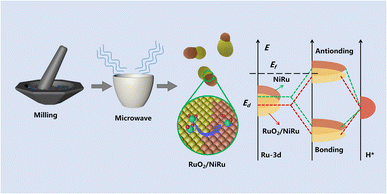
:![[thin space (1/6-em)]](https://www.rsc.org/images/entities/char_2009.gif) 1, respectively (Table S2†). As shown in Fig. 1, NixRuy/C samples were prepared through a two-step procedure (x and y represent the fed molar ratios of Ni and Ru metals, respectively). First of all, ball-milling was used to mix RuCl3·3H2O, Ni(acac)2 and carbon black well for 3 hours to get the powder precursors. Secondly, 300.0 mg of the mixture should be placed in a microwave reactor and then heated for 3 minutes with a power of 900 W in air, after which multi-active site NixRuy/C was successfully obtained. The HER property measurement showed that the optimal ratio of Ni/Ru is 1
1, respectively (Table S2†). As shown in Fig. 1, NixRuy/C samples were prepared through a two-step procedure (x and y represent the fed molar ratios of Ni and Ru metals, respectively). First of all, ball-milling was used to mix RuCl3·3H2O, Ni(acac)2 and carbon black well for 3 hours to get the powder precursors. Secondly, 300.0 mg of the mixture should be placed in a microwave reactor and then heated for 3 minutes with a power of 900 W in air, after which multi-active site NixRuy/C was successfully obtained. The HER property measurement showed that the optimal ratio of Ni/Ru is 1![[thin space (1/6-em)]](https://www.rsc.org/images/entities/char_2009.gif) :
:![[thin space (1/6-em)]](https://www.rsc.org/images/entities/char_2009.gif) 1 in NixRuy/C (denoted as Ni1Ru1/C). The ink was prepared by ultrasonically mixing 2.0 mg of NixRuy/C, 0.1 mL of ethylene glycol and 15 μL Nafion, which was then dropped onto carbon paper and dried overnight to get the NixRuy/C electrode for electrochemical measurements. The details of the main reagents and instruments are listed in Table S3.†
1 in NixRuy/C (denoted as Ni1Ru1/C). The ink was prepared by ultrasonically mixing 2.0 mg of NixRuy/C, 0.1 mL of ethylene glycol and 15 μL Nafion, which was then dropped onto carbon paper and dried overnight to get the NixRuy/C electrode for electrochemical measurements. The details of the main reagents and instruments are listed in Table S3.†
2.2 Characterization
Scanning electron microscopy (SEM) was performed on a JSM-IT500HR/LA. Transmission electron microscopy (TEM) and scanning transmission electron microscopy (STEM) measurements were performed on a JEM-F200 and JEM-1400plus. X-ray powder diffraction (XRD) patterns were acquired using a D8 Advance. X-ray photoelectron spectroscopy (XPS) measurements were conducted on an ESCALAB 250Xi. The contact angle analysis was performed with a KRUSS DSA25. ICP-OES was conducted on an ICP-OES Icap7400.2.3 Electrochemical measurements
All HER tests were performed at room temperature with a conventional three-electrode system which employed a Hg/HgO reference electrode and a platinum net counter electrode, and an electrolyte of 1.0 M KOH. The NixRuy/C electrode was used as the working electrode with the area immersed in the electrolyte being 1 cm × 1 cm. The loading of the Ni1Ru1/C catalyst was 1.86 mg cm−2. The potential in this work was referenced to a reversible hydrogen electrode (RHE) scale according to the Nernst equation in 1.0 M KOH (Evs. RHE = Evs. Hg/HgO + 0.098 + 0.05916 pH). Linear sweep voltammetry (LSV) with auto iR correction and electrochemical impedance spectroscopy (EIS) with a frequency range from 100 kHz to 0.1 Hz were performed using a Gamry electrochemical workstation. Electrochemically active surface areas (ECSAs) of the NixRuy/C electrodes were measured using a CHI 660E electrochemical workstation and were determined using double-layer capacitance (Cdl), which can be determined by calculating the slope in the linear relationship of current density with a scan rate increase.2.4 DFT calculations
DFT calculations were performed with the Vienna ab initio simulation package (VSAP), with the projector augmented wave (PAW) potentials to describe the electron–ion interactions. The generalized gradient approximation (GGA) with the Perdew–Burke–Ernzerhof (PBE) functional was used for the exchange-correlation potentials. The cutoff energy for the plane-wave basis set was 450 eV. The long-range dispersion interactions between the adsorbates and catalyst surface were illustrated by the D3 correction method.31 The Brillouin zone was sampled with 3 × 3 × 1 gamma-centered k-mesh for metal oxide slabs and 2 × 2 × 1 k-mesh for the alloy/oxide interface. Geometries of all the structures were optimized with the conjugate gradient algorithm and the convergence tolerances for residual energy and force were 10−4 eV and 0.02 eV Å−1.RuO2(110) and NiO(100) were modeled as a periodic four-layer p(3 × 3) model with the 2 lower layers fixed and 2 upper layers relaxed. NiRu(101) was modeled as the 2 × 3 supercell of c(√2 × √2) − 45. To simulate the RuO2/NiRu interface, the NiRu cluster containing 4 Ni and 4 Ru atoms was placed on RuO2(110). The simulation of the Ru/NiRu interface was the same as that of the RuO2/NiRu interface, except for replacing RuO2(110) with Ru(101). A vacuum space of 15 Å perpendicular to the surface was applied to separate the interaction between the neighboring slabs.
The adsorption free energies of hydrogen were defined as:
| ΔEH = EH* − (E* +1/2EH2) |
| ΔG = ΔEH + ΔZPE − TΔS |
3 Results and discussion
3.1 Characterization of NixRuy/C
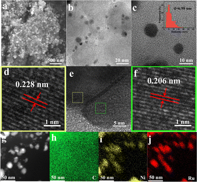
As depicted in Fig. 1, the NixRuy/C samples were prepared through a facile microwave method; the carbon black substrate was mixed with Ni and Ru precursors with grinding treatment, followed by microwave irradiation, and then the targeted carbon supported NiRu composite material was obtained. The scanning electron microscope (SEM) image (Fig. 2a) indicated that the Ni1Ru1/C sample was composed of small nanoparticles anchored on the carbon substrate. Further transmission electron microscopy (TEM) characterization and size distribution analysis (Fig. 2b and c) suggested that the particle size mainly ranged from 1.8 to 20 nm and the average particle size was 6.98 nm. The smaller nanoparticles should be more favorable for the exposure of active sites.5,33,34 As depicted in Fig. 2e, a heterogeneous interface (denoted as RuO2/NiRu) was observed on the Ni1Ru1/C sample. High-resolution TEM (HRTEM) showed lattice fringe distances of 0.228 and 0.206 nm, ascribed to the (200) facets of RuO2 and the (0002) facets of the NiRu alloy, respectively. Moreover, NiO, RuO2, and NiRu alloy species were observed on the Ni1Ru1/C sample from HRTEM (Fig. S3 and S4†), and the selected-area electron diffraction (SAED, Fig. S5†) pattern further confirmed the existence of the as-mentioned species. Fig. 2g–j display scanning transmission electron microscopy (STEM) images and the corresponding energy-dispersive spectrometry (EDS) mappings; the results suggested that Ni and Ru were homogeneously distributed on the nanoparticles supported by carbon black. These data confirmed that the multi-active site catalyst of Ni1Ru1/C with the RuO2/NiRu heterogeneous interface was successfully fabricated.3.2 HER performance of NixRuy/C
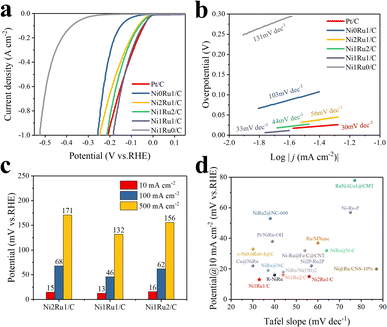
The effect of the metal ratio of Ni/Ru on the electrochemical performance of multi-active site NixRuy/C catalysts was studied. The electrochemical performance was evaluated in a N2-saturated 1 M KOH aqueous solution with a classical three-electrode system. From the linear sweep voltammetry polarization curves (LSV, Fig. 3a), we found that the HER catalytic performance was significantly improved after the introduction of Ni, indicating the importance of Ni in improving the catalytic performance of the HER. The catalytic performance could be further optimized through regulating the ratio of Ni/Ru, and the best HER catalytic performance was achieved when the Ni/Ru ratio was 1![[thin space (1/6-em)]](https://www.rsc.org/images/entities/char_2009.gif) :
:![[thin space (1/6-em)]](https://www.rsc.org/images/entities/char_2009.gif) 1. It was worth noting that the overpotential on the Ni1Ru1/C sample was only 13 mV at a current density of 10 mA cm−2, which was close to that of commercial Pt/C (11 mV) and smaller than those on Ni2Ru1/C (16 mV) and Ni1Ru2/C (15 mV), respectively (Fig. 3c). Thus, the amounts of Ni in NixRuy/C composite catalysts had a great influence on the catalytic performance of alkaline HER, and the Ni1Ru1/C sample possessed a more optimized Ni/Ru molar ratio to achieve a higher apparent current density than samples with other ratios with the same overpotential. Surprisingly, the Ni1Ru1/C sample even exhibited better HER activity than the Pt/C sample at large current densities (greater than 500 mA cm−2). By converting the apparent current density into mass current density, the mass activity could be compared more intuitively (Fig. S14 and Table S6†). At an overpotential of 10 mV, the mass current density of Ni1Ru1 was about 22.7, 18.7 and 14.2 times higher than those of Ni2Ru1/C, Ni1Ru2/C and Pt/C, respectively, which indicated higher intrinsic activity of Ni1Ru1/C.
1. It was worth noting that the overpotential on the Ni1Ru1/C sample was only 13 mV at a current density of 10 mA cm−2, which was close to that of commercial Pt/C (11 mV) and smaller than those on Ni2Ru1/C (16 mV) and Ni1Ru2/C (15 mV), respectively (Fig. 3c). Thus, the amounts of Ni in NixRuy/C composite catalysts had a great influence on the catalytic performance of alkaline HER, and the Ni1Ru1/C sample possessed a more optimized Ni/Ru molar ratio to achieve a higher apparent current density than samples with other ratios with the same overpotential. Surprisingly, the Ni1Ru1/C sample even exhibited better HER activity than the Pt/C sample at large current densities (greater than 500 mA cm−2). By converting the apparent current density into mass current density, the mass activity could be compared more intuitively (Fig. S14 and Table S6†). At an overpotential of 10 mV, the mass current density of Ni1Ru1 was about 22.7, 18.7 and 14.2 times higher than those of Ni2Ru1/C, Ni1Ru2/C and Pt/C, respectively, which indicated higher intrinsic activity of Ni1Ru1/C.
The Tafel slope plots were extracted from the linear portions of the LSV curves in order to study the reaction kinetics of the HER process. As depicted in Fig. 3b, the Tafel slope of the Ni1Ru1/C sample was 33 mV dec−1, which was almost the same as the 30 mV dec−1 of the Pt/C sample and smaller than 44 mV dec−1 of the Ni1Ru2/C sample and 56 mV dec−1 of the Ni2Ru1/C sample. The Tafel slope suggested that the HER on the Ni1Ru1/C sample might be processed via the Volmer–Tafel mechanism.28,35,36 The improvement of the kinetic process might originate from the synergic catalytic effect of Ni and Ru,28 and the optimized molar ratio of Ni and Ru on the Ni1Ru1/C sample might further promote such a reaction process compared to Ni2Ru1/C or Ni1Ru2/C. From the perspective of overpotential at a current density of 10 mA cm−2 and the Tafel slope, our Ni1Ru1/C sample showed better catalytic performance than relevant NiRu-based HER catalysts reported in the literature previously (Fig. 3d and Table S1†).
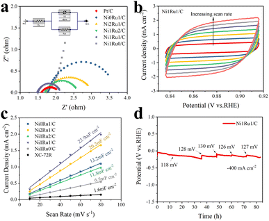
To further understand the origin of the excellent catalytic performance of the NixRuy/C composite samples, electrochemical impedance spectroscopy (EIS) and electrochemically active surface area (ECSA) analyses of several multi-active site NixRuy/C samples were carried out. EIS was used to evaluate the charge transfer resistance of the electrodes during the electrocatalytic reaction process. The corresponding equivalent circuit is shown in the inset, which was composed of Rs (the ohmic resistance of the electrolyte), Rct (charge transfer resistance) and Y0 (constant phase elements).18 The diameter of the half cycle shown in Fig. 4a of Ni1Ru1/C (0.651 ohm) was obviously smaller than that of Ni0Ru1/C (1.938 ohm), Ni1Ru2/C (0.933 ohm), and Ni2Ru1/C (1.372 ohm), indicating that the Ni1Ru1/C sample should have a lower contact resistance and a faster electron transfer process during the HER than the control samples.37 The Rct of catalysts was significantly reduced due to the introduction of Ni, and thus the corresponding kinetic process of the HER was greatly promoted.23Fig. 4b and S7† present the cyclic voltammetry (CV) curves of NixRuy/C electrodes at different scan rates. As shown in Fig. 4c, the calculated double-layer capacitance (Cdl) of Ni1Ru1/C was 23.9 mF cm−2, which was larger than 20.2 mF cm−2 of Ni2Ru1/C, 13.2 mF cm−2 of Ni0Ru1/C, 11.8 mF cm−2 of Ni1Ru2/C, and 6.5 mF cm−2 of Ni1Ru0/C, suggesting an exposure of more abundant active sites on Ni1Ru1/C than the control samples. When the Ni/Ru ratio is 1, the number of active sites might increase, which leads to the largest ECSA of the Ni1Ru1/C sample. And the higher ECSA of the Ni1Ru1/C was one of the important causes of enhanced HER activity. These results seem to support our initial hypothesis that the introduction of RuO2/NiRu heterogeneous interfaces might serve as an effective strategy to improve the catalytic activity.
In order to evaluate the stability and durability of the Ni1Ru1/C catalyst and its application potential in industrial water electrolysis, the Ni1Ru1/C electrode was tested in 1 M KOH electrolyte at a current density of 400 mA cm−2 for over 80 hours (Fig. 4d). After 80 hours of galvanostatic testing, the increase in overpotential appeared negligible, indicating that the Ni1Ru1/C electrode was able to maintain satisfactory durability in the alkaline HER catalysis process. Though there was a slightly reduced signal for the decreased amount of RuO2(211), no obvious Ru0 signal was presented in the XRD spectrum shown in Fig. S9.† The ratio of Ru4+ to Ru0 on the post-electrode surface did not change significantly in XPS patterns (Fig. S13 and Table S5†). The XRD and XPS results indicated that most RuO2 had not been reduced. And the SEM images and contact angle results of the electrode surface before and after the HER measurement showed that the morphology of the electrode surface remained basically unchanged (Fig. S8 and S11†). Therefore, the morphology of the electrode surface remained basically unchanged during the 80 h HER test, which suggested its application potential in industrial WS.
3.3 The study of local electron modulation for the RuO2/NiRu heterogeneous interface
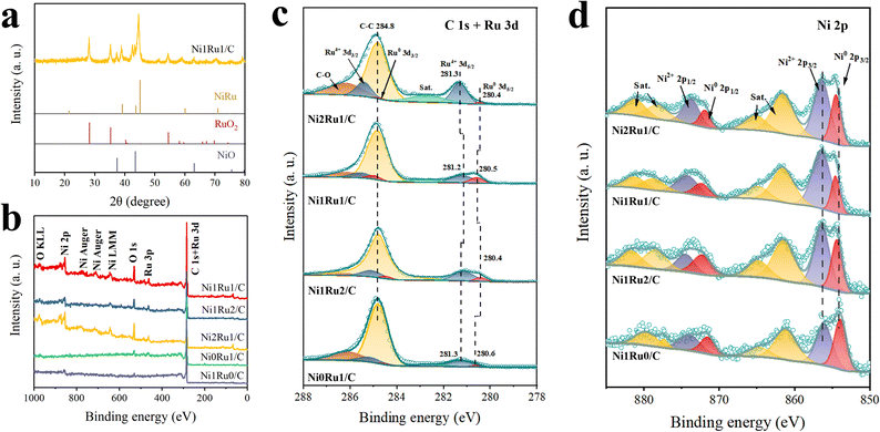
In order to further study the localized electron modulation in the multi-active sites of Ni1Ru1/C and rationalize the improved alkaline HER activity, we carried out XRD and XPS characterization tests on the synthesized catalysts. As shown in the XRD pattern (Fig. 5a), Ni1Ru1/C was mainly composed of a NiRu alloy, RuO2 and NiO, which was consistent with XPS characterization. As shown in Fig. 5c, 280.6 and 281.3 eV in Ni0Ru1/C correspond to the Ru0 of Ru metal and Ru4+ of RuO2, respectively. As shown in Fig. 5d, Ni1Ru0/C shows two signals at 854.7 and 856.5 eV corresponding to Ni0 of Ni metal and Ni2+ of NiO, respectively. When the corresponding peaks were compared with those of Ni1Ru1/C, it could be seen that when Ni was introduced to form the NiRu alloy, the binding energy of Ru0 shifted negatively while positive shifts occurred on Ni0 peaks. This indicated that electrons were transferred from Ni to Ru in NiRu alloys due to the smaller electronegativity of Ni relative to that of Ru, leading to the interatomic charge polarization in the NiRu alloys.28 In addition, the results of XPS peak analysis indicated that feeding different metal ratios of Ni to Ru can change the ratio of Ru0 to Ru4+ on the surface of the synthesized material. Thus, the introduction of Ni can influence the formation of the NiRu alloy. The difference in the positional shift of the binding energy of Ni0 in Ni2Ru1/C, Ni1Ru2/C and Ni1Ru1/C suggested a difference in the degree of electronic coupling between Ni and Ru.38 Among them, the deviation degree of Ni0 in Ni1Ru1/C was the largest, suggesting that there was a stronger local electronic modulation on the surface of the catalyst. Furthermore, compared with Ni2Ru1/C and Ni1Ru2/C, the peak of Ru0 in Ni1Ru1/C had a positive shift of 0.1 eV and a negative shift of 0.1 eV also occurred to the Ru4+ peak, which might be caused by electron transfer from NiRu to RuO2 at the interface of RuO2/NiRu. Such an electron effect may also be one of the reasons for the aforementioned deviation enhancement of the Ni0 peak. The results showed that there might be a stronger local electron modulation at the RuO2/NiRu heterogeneous interface, thus speeding up the electron transfer and charge transfer in the catalytic reaction for alkaline HER.3.4 The DFT calculation study for the RuO2/NiRu heterogeneous interface
It was accepted that the alkaline HER followed the Volmer–Heyrovsky or Volmer–Tafel mechanism.39,40 The H–O–H bond of water molecules first needed to break to form H* and OH−, and the Volmer step (eqn (1.1)) involved the adsorption and dissociation of water molecules on the catalyst surface.41 Next, a hydrogen generation step occurred on the surface with the Heyrovsky step (eqn (1.2)) or Tafel step (eqn (1.3)).36| Volmer step: H2O + M + e− → M–H* + OH− | (1.1) |
| Heyrovsky step: M–H* + H2O + e− → M + OH− + H2 | (1.2) |
| Tafel step: 2M–H* → 2M + H2 | (1.3) |
Though the Tafel slope could not be used to determine the specific mechanism of the HER, the value of the Tafel slope has been generally used to analyze the rate-determination steps in the reaction process according to the Bulter–Volmer equation.28,35,36 Combined with research studies on Ru-based catalysts1,9,42 and Tafel slope,43,44 the HER on the Ni1Ru1/C might be processed via the Volmer–Tafel mechanism.
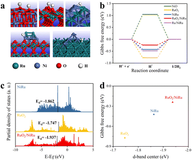
To probe the potential effect of the RuO2/NiRu interface, the Gibbs free energy of hydrogen adsorption (ΔGH*), a good descriptor that may partially rationalize HER catalytic activity, was calculated using DFT. It indicated optimal hydrogen adsorption and release when ΔGH* was close to zero.45,46 The RuO2/NiRu interface model was constructed for DFT calculations. Given the partial reduction of RuO2 of RuO2/NiRu after the HER test, a Ru/NiRu model was also simulated. Fig. 6a shows the optimized NiO, RuO2, NiRu alloys, RuO2/NiRu interface and Ru/NiRu interface for the hydrogen atom adsorption model, respectively. Our DFT calculation results showed that ΔGH* on the RuO2/NiRu heterogeneous interface (−0.240 eV) was much closer to zero than those of NiO (1.047 eV), RuO2 (−0.772 eV) and NiRu alloy (−0.422 eV), indicating that the formation of the RuO2/NiRu heterogeneous interface was able to modulate the hydrogen adsorption strength thereby improving the HER performance of Ni1Ru1/C (Fig. 6b). And the ΔGH* of RuO2/NiRu interface was also closer to zero than ΔGH* of the Ru/NiRu interface, suggesting that the former has higher HER activity than the latter. Since no significant increase in overpotential was observed in the 80 h CP test of Ni1Ru1/C, it should be reasonable to propose that RuO2/NiRu should be the most active component of Ni1Ru1/C. The analysis of PDOS illustrated that the RuO2/NiRu interface presented a downshifted d-band center and a trend away from the Fermi level, which is consistent with the weakening of the H adsorption energy (Fig. 6c). As the Sabatier principle described, an active catalyst binds reaction intermediate(s) neither too strongly nor too weakly.45,47 Thus, the computational results also support our original speculation that the formation of the RuO2/NiRu heterogeneous interface can weaken the too-strong adsorption of H*,47 leading to the corresponding ΔGH* being close to a desirable value (Fig. 6d). Additionally, RuO2 might play the important role of strengthening *OH adsorption, which was beneficial for the promotion of the Volmer step.48 By combining the weakened *H adsorption and enhanced *OH adsorption,48,49 a reasonable hypothesis can be made that the interfacial synergy between NiRu and RuO2 might boost the HER activities.
4 Conclusions
In summary, we prepared a series of multi-active site NiRu bimetallic materials through a facile microwave synthesis method. The introduction of Ni to form NiRu bimetallic electrocatalysts has led to significantly improved HER catalytic performance; furthermore, the NiRu/RuO2 heterogeneous interface was successfully constructed on the Ni1Ru1/C sample to further improve the HER catalytic performance. The optimized Ni1Ru1/C sample exhibited an overpotential of only 13 mV at a current density of 10 mA cm−2 under alkaline conditions, outperforming state-of-the-art results reported in the previous literature; moreover, excellent stability for more than 80 h at 400 mA cm−2 was achieved. A combination of experimental and computational studies suggested that a faster electron transfer process, higher ECSA, and the presence of the NiRu/RuO2 heterogeneous interface jointly contributed to the observed improvement in HER catalytic activity.Conflicts of interest
There are no conflicts to declare.Acknowledgements
We would like to acknowledge the support from the Analytical Instrumentation Center of the Schools of Physical Science and Technology (SPST), ShanghaiTech University.Notes and references
- Y. Xu, S. S. Yu, T. L. Ren, S. L. Liu, Z. Q. Wang, X. N. Li, L. Wang and H. J. Wang, ACS Appl. Mater. Interfaces, 2020, 12, 34728 CrossRef CAS PubMed.
- T. Lim and S. K. Kim, Chem. Eng. J., 2022, 433, 1385–8947 Search PubMed.
- W. H. Zhang, B. Q. Zhang, Y. A. Li, E. Z. Zhang, Y. Zhang, Q. Wang and Y. Q. Cong, Int. J. Hydrogen Energy, 2022, 47, 1633 CrossRef CAS.
- J. He, X. Zhou, P. Xu and J. M. Sun, Adv. Energy Mater., 2021, 2102883 CrossRef CAS.
- T. T. Gao, X. Q. Li, X. J. Chen, C. X. Zhou, Q. Yue, H. Y. Yuan and D. Xiao, Chem. Eng. J., 2021, 424, 130416 CrossRef CAS.
- Y. Lu, D. Guo, Y. F. Zhao, Y. J. Zhao, S. P. Wang and X. B. Ma, Appl. Catal., B, 2021, 291, 120075 CrossRef CAS.
- Y. Ishikawa, J. J. Mateo, D. A. Tryk and C. R. Cabrera, J. Electroanal. Chem., 2007, 607, 37 CrossRef CAS.
- C. Cai, K. Liu, Y. M. Zhu, P. C. Li, Q. Y. Wang, B. Liu, S. Y. Chen, H. J. W. Li, L. Zhu, H. M. Li, J. W. Fu, Y. Chen, E. Pensa, J. H. Hu, Y. R. Lu, T. S. Chan, E. Cortes and M. Liu, Angew. Chem., Int. Ed., 2022, 61, e202113664 CAS.
- C. Yang, Z. Wu, Z. Zhao, Y. Gao, T. Ma, C. He, C. Wu, X. Liu, X. Luo, S. Li, C. Cheng and C. Zhao, Small, 2023, 2206949 CrossRef PubMed.
- X. K. Wu, Z. C. Wang, D. Zhang, Y. N. Qin, M. H. Wang, Y. Han, T. R. Zhan, B. Yang, S. X. Li, J. P. Lai and L. Wang, Nat. Commun., 2021, 12, 4018 CrossRef CAS PubMed.
- Y. X. Fan, X. D. Zhang, Y. J. Zhang, X. Xie, J. Ding, J. L. Cai, B. J. Li, H. L. Lv, L. Y. Liu, M. M. Zhu, X. C. Zheng, Q. Cai, Y. S. Liu and S. Y. Lu, J. Colloid Interface Sci., 2021, 604, 508 CrossRef CAS PubMed.
- J. T. Zhang, X. N. Mao, S. L. Wang, L. L. Liang, M. F. Cao, L. Wang, G. Li, Y. Xu and X. Q. Huang, Angew. Chem., Int. Ed., 2022, 134, e202116867 Search PubMed.
- P. P. Su, W. Pei, X. W. Wang, Y. F. Ma, Q. K. Jiang, J. Liang, S. Zhou, J. J. Zhao, J. Liu and G. Q. Lu, Angew. Chem., Int. Ed., 2021, 60, 16044 CrossRef CAS PubMed.
- J. Q. Jiao, N. N. Zhang, C. Zhang, N. Sun, Y. Pan, C. Chen, J. Li, M. J. Tan, R. X. Cui, Z. L. Shi, J. W. Zhang, H. Xiao and T. B. Lu, Adv. Sci., 2022, 9, 2200010 CrossRef CAS PubMed.
- J. Yu, Q. J. He, G. M. Yang, W. Zhou, Z. P. Shao and M. Ni, ACS Catal., 2019, 9, 9973 CrossRef CAS.
- B. Z. Lu, L. Guo, F. Wu, Y. Peng, J. E. Lu, T. J. Smart, N. Wang, Y. Z. Finfrock, D. Morris, P. Zhang, N. Li, P. Gao, Y. Ping and S. W. Chen, Nat. Commun., 2019, 10, 631 CrossRef CAS PubMed.
- J. L. Cai, J. Ding, D. H. Wei, X. Xie, B. J. Li, S. Y. Lu, J. M. Zhang, Y. S. Liu, Q. Cai and S. Q. Zhang, Adv. Energy Mater., 2021, 11, 2100141 CrossRef CAS.
- Q. F. Yang, P. Jin, B. Liu, L. Zhao, J. H. Cai, Z. Wei, S. W. Zuo, J. Zhang and L. Feng, J Mater Chem A, 2020, 8, 9049 RSC.
- Z. Zhao, X. Wang, J. Si, C. Yue, C. Xia and F. Li, Green Chem., 2018, 20, 832 RSC.
- Y. Y. Liu, H. Wen, D. J. Zhou, X. Y. Huang, X. L. Wu, J. C. Jiang, X. J. Guo and B. J. Li, Appl. Catal., B, 2021, 291, 120094 CrossRef CAS.
- Z. K. Peng, J. M. Liu, B. Hu, Y. P. Yang, Y. Q. Guo, B. J. Li, L. Li, Z. H. Zhang, B. B. Cui, L. H. He and M. Du, ACS Appl. Mater. Interfaces, 2020, 12, 13842 CrossRef CAS PubMed.
- A. Q. Kong, M. Peng, H. Z. Gu, S. C. Zhao, Y. Lv, M. H. Liu, Y. W. Sun, S. D. Dai, Y. Fu, J. L. Zhang and W. Li, Chem. Eng. J., 2021, 426, 131234 CrossRef CAS.
- S. K. Xu, Z. Q. Li, K. N. Chu, G. Yao, Y. Xu, P. Niu and F. C. Zheng, Dalton Trans., 2020, 49, 13647 RSC.
- X. Han, T. Q. Si, Q. N. Liu, F. F. Zhu, R. J. Li, X. Y. Chen, J. C. Liu, H. Sun, J. G. Zhao, H. Ling, Q. H. Zhang and H. Z. Wang, Chem. Eng. J., 2021, 426, 130824 CrossRef CAS.
- M. Sarno, E. Ponticorvo and D. Scarpa, Electrochem. Commun., 2020, 111, 106647 CrossRef CAS.
- M. X. Li, H. Y. Wang, W. D. Zhu, W. M. Li, C. Wang and X. F. Lu, Adv. Sci., 2020, 7, 1901833 CrossRef CAS PubMed.
- P. Z. Yang, C. Q. Ma and Q. W. Tang, Electrochim. Acta, 2015, 184, 226 CrossRef CAS.
- G. G. Liu, W. Zhou, B. Chen, Q. H. Zhang, X. Y. Cui, B. Li, Z. C. Lai, Y. Chen, Z. C. Zhang, L. Gu and H. Zhang, Nano Energy, 2019, 66, 104173 CrossRef CAS.
- T. Lian, X. Y. Li, Y. L. Wang, S. J. Zhu, X. Y. Yang, Z. Liu, C. F. Ye, J. P. Liu, Y. Li, B. L. Su and L. H. Chen, ACS Appl. Mater. Interfaces, 2022, 14, 30746 CrossRef CAS PubMed.
- R. Majee, S. Parvin, Q. A. Islam, A. Kumar, B. Debnath, S. Mondal, S. Bhattacharjee, S. Das, A. Kumar and S. Bhattacharyya, Chem. Rec., 2022, 22, e202200070 CrossRef CAS PubMed.
- S. Grimme, J. Antony, S. Ehrlich and H. Krieg, J. Chem. Phys., 2010, 132, 154104 CrossRef PubMed.
- V. Wang, N. Xu, J. C. Liu, G. Tang and W. T. Geng, Comput. Phys. Commun., 2021, 267, 108033 CrossRef CAS.
- H. Wang, M. Ming, M. Hu, C. L. Xu, Y. Wang, Y. Zhang, D. J. Gao, J. Bi, G. Y. Fan and J. S. Hu, ACS Appl. Mater. Interfaces, 2018, 10, 22340 CrossRef CAS PubMed.
- T. T. Gao, C. X. Zhou, X. J. Chen, Z. H. Huang, H. Y. Yuan and D. Xiao, J Mater Chem A, 2020, 8, 18367 RSC.
- L. S. Zhang, J. J. Lu, S. B. Yin, L. Luo, S. Y. Jing, A. Brouzgou, J. H. Chen, P. K. Shen and P. Tsiakaras, Appl. Catal., B, 2018, 230, 58 CrossRef CAS.
- S. Y. Jing, L. S. Zhang, L. Luo, J. J. Lu, S. B. Yin, P. K. Shen and P. Tsiakaras, Appl. Catal., B, 2018, 224, 533 CrossRef CAS.
- X. Y. Chen, J. W. Wan, J. Wang, Q. H. Zhang, L. Gu, L. R. Zheng, N. Wang and R. B. Yu, Adv. Mater., 2021, 33, 2104764 CrossRef CAS PubMed.
- D. Yang, P. Li, X. Y. Gao, J. L. Han, Z. Y. Liu, Y. P. Yang and J. H. Yang, Chem. Eng. J., 2022, 432, 134422 CrossRef CAS.
- J. D. Benck, T. R. Hellstern, J. Kibsgaard, P. Chakthranont and T. F. Jaramillo, ACS Catal., 2014, 4, 3957 CrossRef CAS.
- Y. Jiao, Y. Zheng, M. T. Jaroniec and S. Z. Qiao, Chem. Soc. Rev., 2015, 44, 2060 RSC.
- M. Gong, D. Y. Wang, C. C. Chen, B. J. Hwang and H. J. Dai, Nano Res., 2016, 9, 28 CrossRef CAS.
- Y. Xu, S. L. Yin, C. J. Li, K. Deng, H. R. Xue, X. N. Li, H. J. Wang and L. Wang, J Mater Chem A, 2018, 6, 1376 RSC.
- Y. M. Shi and B. Zhang, Chem. Soc. Rev., 2016, 45, 1781 RSC.
- T. Shinagawa, A. T. Garcia-Esparza and K. Takanabe, Sci. Rep., 2020, 10, 13801 CrossRef PubMed.
- Z. W. Seh, J. Kibsgaard, C. F. Dickens, I. B. Chorkendorff, J. K. Norskov and T. F. Jaramillo, Science, 2017, 355, 6321 CrossRef PubMed.
- N. Wang, S. L. Ning, X. L. Yu, D. Chen, Z. L. Li, J. C. Xu, H. Meng, D. K. Zhao, L. G. Li, Q. M. Liu, B. Z. Lu and S. W. Chen, Appl. Catal., B, 2022, 302, 120838 CrossRef CAS.
- M. Kim, J. Park, H. Ju, J. Y. Kim, H. S. Cho, C. H. Kim, B. H. Kim and S. W. Lee, Energy Environ. Sci., 2021, 14, 3053 RSC.
- G. Q. Zhao, Y. Z. Jiang, S. X. Dou, W. P. Sun and H. G. Pan, Sci. Bull., 2021, 66, 85 CrossRef CAS PubMed.
- B. Hammer and J. K. Norskov, Nature, 1995, 376, 238 CrossRef CAS.
Footnote |
| † Electronic supplementary information (ESI) available. See DOI: https://doi.org/10.1039/d2ta09660a |
| This journal is © The Royal Society of Chemistry 2023 |

