
 Open Access Article
 This Open Access Article is licensed under a
 Creative Commons Attribution 3.0 Unported Licence
Sodiation energetics in pore size controlled hard carbons determined via entropy profiling†
Michael P.
Mercer
 *abc,
Mangayarkarasi
Nagarathinam
bc,
E. Maximiliano
Gavilán-Arriazu
de,
Anshika
Binjrajka‡
b,
Swoyam
Panda§
b,
Heather
Au
f,
Maria
Crespo-Ribadeneyra
fg,
Maria-Magdalena
Titirici
f,
Ezequiel P. M.
Leiva
d and
Harry E.
Hoster
bch
*abc,
Mangayarkarasi
Nagarathinam
bc,
E. Maximiliano
Gavilán-Arriazu
de,
Anshika
Binjrajka‡
b,
Swoyam
Panda§
b,
Heather
Au
f,
Maria
Crespo-Ribadeneyra
fg,
Maria-Magdalena
Titirici
f,
Ezequiel P. M.
Leiva
d and
Harry E.
Hoster
bch
aFaculty of Mechanical Engineering, Helmut-Schmidt University, Holstenhofweg 85, 22043 Hamburg, Germany. E-mail: mercerm@hsu-hh.de
bDepartment of Chemistry, Lancaster University, Bailrigg, Lancaster, LA1 4YB, UK
cThe Faraday Institution, Quad One, Harwell Science and Innovation Campus, Didcot, UK
dDepartamento de Química Teórica y Computacional, Facultad de Ciencias Químicas, Universidad Nacional de Córdoba, INFIQC, Córdoba, Argentina
eFacultad de Matemática, Astronomía y Física, IFEG-CONICET, Universidad Nacional de Córdoba, Córdoba, Argentina
fDepartment of Chemical Engineering, Imperial College London, London, UK
gSchool of Engineering and Materials Science, Queen Mary University of London, Mile End Road, London E1 4NS, UK
hDepartment of Mechanical and Process Engineering, University Duisburg-Essen, Lotharstraße 1, 47057 Duisburg, Germany
First published on 24th February 2023
Abstract
Hard carbons show considerable potential as anode materials in emerging sodium-ion battery technologies. Recent work suggests sodiation of hard carbon proceeds by insertion of sodium at defects, within the interlayers and inside the nanopores. The energetics of these processes dictate the characteristic sloping region and plateau when hard carbon is charged/discharged with sodium. However, the driving forces affecting these processes, and particularly sodium filling into nanopores, are under debate and are holding back controlled material optimisation. We apply entropy profiling (EP), where the cell temperature is changed under open circuit conditions, to yield additional insights into sodium insertion in hard carbons of systematically controlled pore size. Features from EP vary with the pore size, allowing us to precisely determine the onset of nanopore filling. Comparing the system entropy and enthalpy data to models, we can quantify the energetics of sodium inside the nanopores. The average binding energy of sodium in the pores is found to be inversely proportional to the pore radius of curvature, which is attributed to the scaling of the surface area to volume inside the pores. This simple structure–property relationship provides a rational framework to tune the cell cut-off voltage of sodium-ion cells based on hard carbon, potentially enabling future materials of improved safety and longevity.
1 Introduction
The demand for clean and sustainable energy sources necessitates effective and low cost energy storage solutions. Lithium-ion batteries (LIBs) have revolutionalised portable devices and are leading the drive for automotive electrification. The cost of the raw materials of LIBs, and the fact that lithium is limited in supply and unevenly distributed throughout the globe raises challenges for applications of LIBs in stationary storage and large scale mobile transport areas such as ships.1–3 Sodium-ion batteries (NIBs) replace lithium with much more Earth-abundant sodium. Like LIBs, NIBs comprise an organic electrolyte and various layered transition metal oxides as the cathode material.4,5 However, the usual anode material of choice for LIBs, graphite, does not intercalate sodium to any significant extent,6 and a key challenge for large-scale NIB adoption has been the development of suitable anode materials.Hard carbon has attracted much interest since reports of sodium insertion into its structure by Stevens and Dahn,7,8 who conceptualised the hard carbon as a “house of cards”.7 More recent work suggests that hard carbons consist of randomly oriented, curved and defective layers of graphene separated by large interplanar distances.9–12 Sodium can be inserted at defect sites, between the carbon layers, and into nanopores.7–17 Galvanostatic charge/discharge profiles of hard carbon comprise two main features: (1) a sloping region from the maximum voltage of 2 V (vs. Na) to approximately 0.1 V; (2) a plateau below 0.1 V.18 Stevens and Dahn used small and wide angle X-ray scattering (SAXS/WAXS) to assign sodium intercalation to the sloping voltage region, and filling of the nanopores to the low voltage plateau.8 Nuclear magnetic resonance (NMR) suggested a similar interpretation, additionally revealing that the sodium is deposited in the pores in a “quasi-metallic” state.9,13 Deposition of metallic sodium in the nanopores is also supported by changes to the G-band from Raman spectroscopy.15,16 Techniques such as X-ray photoemission spectroscopy (XPS) have shed light on the evolution of surface species during formation of the solid electrolyte interphase (SEI) on hard carbons;19 while the kinetics of the sodiation process have been studied by electrochemical impedance spectroscopy (EIS).20,21 Insights have also been gained from the study of the sodiation of related model systems, such as nongraphitizable carbons,22 soft carbons,23 and metal–organic frameworks.24
With the exception of the very first cycle, and concomitant features associated with the formation of the SEI,25–29 galvanostatic voltage profiles of hard carbons do not contain any distinct features apart from a slope and plateau. The lack of features leads to ambiguity in determining the transition point between these two regions. However, we showed in a previous work that the transition point can be more objectively determined by measuring the entropy during sodium insertion,30via probing the response of the cell open circuit voltage (OCV) to temperature variation at various different sodiation states of hard carbons. With additional input from lattice gas modelling, the technique can separate the voltage response from sodium insertion in the disordered carbon interlayers versus the nanopores.30 It also allows the voltage itself to be separated into energetic (enthalpy) and configurational (entropy) contributions, which helped to clarify mechanistic details of the various sodium insertion processes.
An open question, addressed in the present work, is the influence of the hard carbon structure on the energetics and entropy of sodium insertion. In particular, for understanding and optimisation of hard carbon anode materials, there is a need to understand the physical mechanisms that make a particular pore geometry favourable (or otherwise) for sodium insertion. The pore insertion energetics dictate not only the capacity of the hard carbon, but also the termination voltage at maximum state of charge when hard carbon is used in full cells. Therefore, the pore filling process ultimately influences the energy density, degradation and safety of NIB cells based on hard carbon.
The main aim of the present work is to quantitatively understand how the energetics of sodium insertion into nanopores are affected by the average pore size. We utilise hard carbons prepared by hydrothermal carbonisation of glucose, which were synthesised, structurally analysed and electrochemically characterised in our previous work.14 Through a combination of entropy profile measurement and modelling, we identify and quantify the key energetic driving terms affecting pore sodiation dependent on pore size. This framework will systematically inform materials development and discovery by highlighting how to target a particular pore geometry to tune the sodium insertion voltage, improving cell safety and lifetime.
2 Methods
2.1 Coin cell assembly
Electrochemical studies were carried out using stainless steel CR2032 2-electrode coin cells. Working electrode materials were prepared by mixing hard carbon powder, prepared according to a previous publication,14 with polyvinylidene fluoride (PVDF, Alfa Aesar) binder in a mass ratio of 90![[thin space (1/6-em)]](https://www.rsc.org/images/entities/char_2009.gif) :10. N-Methyl-2-pyrrolidinone (NMP, anhydrous, 99.5% purity, Sigma Aldrich) was used as the solvent to prepare a slurry, which was cast onto aluminium foil as the current collector. The electrodes were dried at 100 °C overnight, before transferring to an argon-filled glovebox (H2O and O2 levels <0.1 ppm) for cell construction.
:10. N-Methyl-2-pyrrolidinone (NMP, anhydrous, 99.5% purity, Sigma Aldrich) was used as the solvent to prepare a slurry, which was cast onto aluminium foil as the current collector. The electrodes were dried at 100 °C overnight, before transferring to an argon-filled glovebox (H2O and O2 levels <0.1 ppm) for cell construction.
The coin cells were constructed using hard carbon working electrodes of 16 mm diameter against sodium metal (Sigma Aldrich) disks of 16 mm diameter, which were use as the counter and reference electrode. All voltages are, consequently, reported with respect to metallic sodium. Whatman micro glass fibre filters of 20 mm diameter were used as the separator. The electrolyte was 1 M NaClO4 (anhydrous, >98% purity, Alfa Aesar) in a solution mixture of propylene carbonate (PC, anhydrous, 99.7% purity, Sigma Aldrich)/fluoroethylene carbonate (FEC, anhydrous, >99% purity, TCl) in a 98:2 mass ratio. The electrolyte composition with FEC added was based on prior studies showing reduced capacity loss from cycling compared with FEC absent.15,27,31 The PC and FEC were dried in the glovebox using molecular sieves for 48 h before electrolyte preparation.
2.2 Electrochemical characterisation
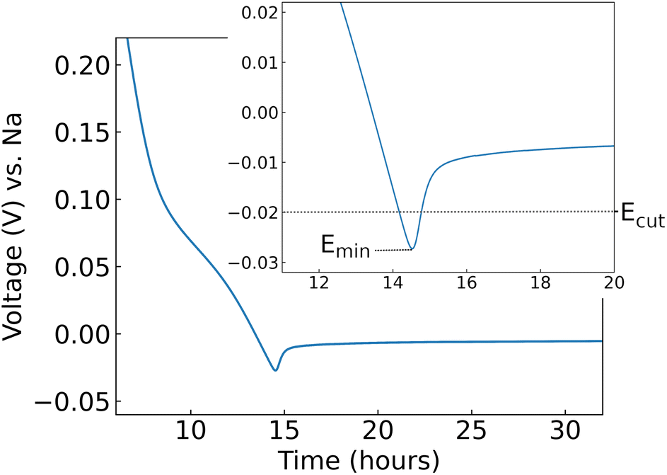 | ||
| Fig. 1 Voltage as a function of time, shown here during galvanostatic cycling at 10 mA g−1. This experiment was used to determine the cycling cut-off voltage (Ecut) used in separate experiments. Here, the characteristic response of hard carbon synthesised at 1000 °C is shown. A voltage minimum, denoted Emin, is observed. Inset: data shown over a narrower voltage range. | ||
2.3 Determination of thermodynamic variables
It is well known34 that the equilibrium cell voltage, ϕ(x), and chemical potential of the guest atom (Na in this case), μ(x), are related as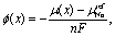 | (1) |
| ϕ(x) = −μ(x). | (2) |
The term μ(x) can also be written as
 | (3) |
Here, we define x (0 ≤ x ≤ 1) as the fraction of sites occupied by sodium in the host. The Bragg–Williams model defined later in Section 2.5.1 allows a theoretical maximum capacity, Qmax, to be determined through fitting the thermodynamic variables to the experimental data. We can then define x as
 | (4) |
The partial molar Gibbs free energy, ΔG, can be written as
 | (5) |
Assuming that the OCV, EOCV, measured at the end of the relaxation period for each x value corresponds to ϕ(x), we can use eqn (2), (3) and (5) to get ∂G/∂x = −EOCV. Hence we obtain
 | (6) |
 | (7) |
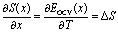
Due to the choice of units of eV per formula unit for the potentials H(x) and TS(x), i.e. as in the conversion between eqn (1) and (2), the usual factors of F have been omitted. In this way, we can relate the partial molar entropy and enthalpy, ΔS and ΔH respectively, in units of eV per inserted Na atom. All of the terms in eqn (6) and (7) are measurable using methods described in Section 2.4.
2.4 Entropy profiling
After checking for representative cycling behaviour (Section 2.2) a constant current/constant voltage (CCCV) charging protocol was performed to ensure a consistent starting sodiation state. This stage consisted of galvanostatic charge at 10 mA g−1 up to 2.5 V, followed by at least 2 hours of polarisation at 2.5 V. This ensured that the hard carbon commenced as close to fully desodiated as possible, in line with protocols previously applied to Li and Na-ion cells.30,32–35We used similar methods as in our previous work30,32–35 to obtain entropy profiles for hard carbon. The method is akin to galvanostatic intermittent titration technique (GITT), comprising alternating steps under galvanostatic control followed by relaxation under open circuit conditions.40,41 In entropy profiling temperature variation is introduced during the relaxation period and entropy is calculated from the gradient of OCV with temperature (by eqn (6)). Measurements comprised iterative steps of galvanostatic discharge at 10 mA g−1 followed by a total of 80 minutes of relaxation time (conditions found to be optimal in our previous study30). The current and temperature were changed dynamically, as outlined in Table 1. Each iteration was repeated until the cell voltage was less than −0.02 V.
| Step | Time (min) | Temperature T (°C) |
|---|---|---|
| Discharge (10 mA g−1) | 20 | 20 |
| OC at T1 | 20 | 20 |
| OC at T2 | 20 | 15 |
| OC at T3 | 20 | 10 |
| OC at T1 | 20 | 20 |
2.5 Mean field model of hard carbon sodiation
The overall goal is to determine a relationship between the geometry of the nanopores and the energetics of sodium insertion into the nanopores. The thermodynamic curves obtained by the methods in Section 2.4 yield the energetics and entropy as a function of sodium concentration. To gain further interpretation, a two step model procedure was used:(1) A two level Bragg–Williams (BW) model was used to separate and assign sodium insertion into interlayers and nanopores (detailed in Section 2.5.1) and hence model the thermodynamic curves measured experimentally in Section 2.4.
(2) The nanopore energetic term obtained from stage 1 is separated into surface (sodium adsorbed to pore walls) and interior (sodium in the second layer or higher) levels. Based on this, an expression is derived to link the nanopore energetic term to the pore radius of curvature measured by SAXS. Further details are in Section 2.5.2.
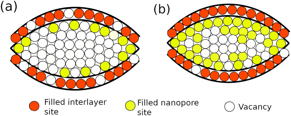 | ||
| Fig. 2 Schematic representation of the model. (a) and (b) show the construction at different sodium concentrations, x. Sodium is intercalated between the curved graphene layers with filling fraction n1 (red sites), and deposited between the porous regions with filling fraction n2 (yellow sites). In (a), the majority of available interlayer sites are filled, but the nanopores are mostly vacant. In (b), nearly all interlayer sites are filled and also there is a significant concentration of sodium inside the nanopores. | ||
| Parameter | Definition |
|---|---|
| N | Total number of filled sites |
| M 1 | Number of interlayer sites |
| M 2 | Number of nanopore sites |
| M tot | Total number of available sites |
| X | Overall sodium concentration x = N/Mtot |
| n 1 | Interlayer sublattice concentration |
| n 2 | Nanopore sublattice concentration |
| T | Absolute temperature (288 K) |
| Fitted parameters | Definition |
|---|---|
| Φ | Ratio of interlayer/total sites |

|
Sum of interlayer interactions between sodium and carbon (eqn (10)) |
| ε 1 | Interlayer point term at high sodium occupation |
| A | Function amplitude |
| B | Function decay constant |

|
Sum of nanopore interactions (eqn (11)) |
| ε 2 | Nanopore point term |
| g 2 | Mean field interaction between Na–Na pairs in the nanopores |
| Q max | Theoretical maximum capacity obtained when x = 1 |
| ΔScorr | Partial molar entropy correction (non-configurational entropy) |
The number of available sites in interlayers and nanopores is denoted by M1 and M2, respectively. While the maximum number of sites in the interlayers or nanopores, Mtot = M1 + M2, is not known a priori, the proportion of available sites can be determined by fitting the modelled thermodynamic partial molar enthalpy and entropy to the same experimental quantities, as we previously demonstrated.30 The ratio of the two types of site thus determined, ϕ (where 0 < ϕ < 1), is given by ϕ = M1/(M1 + M2). The sublattice occupancies, n1 and n2, are defined as n1 = N1/M1 and n2 = N2/M2. From tests of convergence of the simulation results with respect to system size, the total number of sites was set to Mtot = 600.
The model is based on the numerical solution to the partition function, Q(N, M1, M2), defined as
 | (8) |
We can write the interaction Hamiltonian, H(N, M1, M2) as
 | (9) |
The terms  and
and  refer to the interaction terms in the interlayer and pore sublattices, respectively. These terms are given by
 | (10) |
 | (11) |
All of the thermodynamic relationships can easily be obtained from eqn (8). For example, the chemical potential of inserted Na, μ, is
 | (12) |
While the cell voltage contains the energetics and the entropy of sodium insertion lumped into a single quantity through ΔG, from the experiment and model we can separate it into ΔH and ΔS. The respective curves ΔH and ΔS contain features invisible in the voltage profiles,30 and those key features allow us to determine the energetic terms in Table 2.
The sodiation fraction, x (where 0 ≤ x ≤ 1), is determined within the model by
| x = ϕn1 + (1 − ϕ)n2. | (13) |
The model allows the thermodynamic curves to be extrapolated beyond the maximum experimental capacity, Qexpt. The point x = 0 corresponds where the experimental discharge capacity, Q, is zero, because we initialise the experiment from a CCCV condition at 2.5 V. The Qexpt value is attained when the −0.02 V cut-off criterion is reached. However, it is still necessary to account for sites that are not energetically accessible at −0.02 V. Fortunately, this model allows a theoretical maximum capacity, Qmax, to be determined through fitting the thermodynamic variables to the experimental data. We can then convert Q into x using eqn (4).
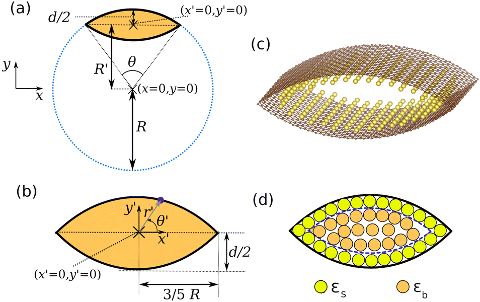 | ||
| Fig. 3 (a) The blue dotted line is the cross section of a cylinder. The orange area is enclosed between two curved graphene sheets, which are represented by black solid lines. The origin of the original Cartesian coordinate system (x, y) is shown. (b) Zoom in of the enclosed area. The origin in the translated Cartesian coordinate system (x′, y′) is shown. Any point along the cross section of the top graphene plane is defined in the polar system (r′, θ′), as shown by the blue point and blue arrow. (c) Atomic scale visualisation of the system, with carbon atoms shown in brown. A monolayer of enclosed sodium atoms is shown in yellow. (d) Separation of nanopore sites into surface sites of energy εs and interior sites of energy εb. For clarity, the interlayer sites shown earlier in Fig. 2 are omitted as they are not considered at this stage of the model. | ||
Let us define a cylinder, radius R, of arbitrary length, L. The outline of this cylinder is given by x2 + y2 = R2 where x and y are Cartesian coordinates with (x = 0, y = 0) defining the centre of the cylinder. The construction is shown in Fig. 3a.
Part of this cylinder defines the outline of a graphene sheet. The cross section of the top graphene sheet is an arc. Stratford et al.9 showed that all hard carbons produced by hydrothermal synthesis exhibited cylindrical curvature. Therefore, they hypothesised that the porous regions within hard carbon can be approximated by curved graphene sheets. If two such graphene sheets are on top of one another, they form a porous region as shown in Fig. 3b. In Fig. 3c, the construction is represented with a monolayer of adsorbed sodium atoms inside the pore. This is an appropriate model system to understand the average local structure of the nanopores.
Through a derivation presented in the ESI,† the coordinates may be transformed from the cylinder-centred system (x, y) to the pore-centred (x′, y′). In a similar spirit to the Brunauer–Emmett–Teller (BET) isotherm, we treat the sodium deposition in two levels: surface and interior (second layer and higher) sites. The surface sites are sodium atoms adsorbed to the curved carbon substrate (as in Fig. 3c), while the interior sites represent sodium deposited either directly on to the surface sites or even further inside the pore, shown in Fig. 3d.
When all of the available sites are filled with sodium, the total sodium adsorption energy ENa is given by
| ENa = VtotρVεb + Stotρsεs | (14) |
| Parameter | Definition |
|---|---|
| E Na | Total sodium adsorption energy |
| V tot | Total enclosed volume inside pores |
| S tot | Total surface area of pore walls |
| ρ V | Interior sodium packing density |
| ρ S | Surface layer sodium packing density |
| R | Cylinder radius |
| L | Cylinder length |
| ε s | Surface term (Na absorbed to C) |
| ε b | Binding term (Na in pore interior) |

|
Nanopore interaction term from BW |
| r avg | Average nanopore radius (from SAXS) |
From geometrical arguments presented in the ESI,† we find that
| ENa = 0.329ρVεbR2L + 1.286ρsεsRL. | (15) |
We can then divide through by the number of bulk atoms to obtain
 | (16) |
When the nanopores are completely filled with sodium, we assume that the number of filled interior sites is much larger than the number of surface sites. Then we can assimilate the first term of eqn (16) into an average binding energy per site,  , which can be determined from the BW model above. We also find that ravg = 0.24R. This relationship is based on earlier pair distribution analysis of hard carbons produced by hydrothermal synthesis9 (full details in the ESI†). Therefore
 | (17) |
Eqn (17) implies that the average energy per Na atom inside the nanopores is inversely proportional to the pore radius of curvature. The other terms in eqn (17) are quantified as part of the analysis in Section 3.4.
3 Results
3.1 Sample data
The materials used in this study were synthesised and characterised in a previous publication.14 Materials were synthesised by hydrothermal carbonisation of glucose, followed by pyrolysis at 1000–1900 °C. For convenience, the structural details relevant to this work are summarised dependent on the sample synthesis temperature, Tsynth, in Table 4.| Synthesis temperature Tsynth (°C) | O at% | C/O | d SAXS (nm) | d(002) (Å) |
|---|---|---|---|---|
| 1000 | 5.9 | 15.9 | 1.2 | 3.743 |
| 1300 | 4.0 | 24.3 | 1.9 | 3.725 |
| 1500 | 3.3 | 29.0 | 2.0 | 3.660 |
| 1700 | 2.3 | 43.9 | 3.7 | 3.636 |
| 1900 | 1.3 | 74.9 | 5.1 | 3.503 |
With increasing Tsynth, the average pore diameter, dSAXS, obtained from small-angle X-ray scattering (SAXS) increases, while the atomic fraction of oxygen and interlayer carbon separation, d(002), decreases. More comprehensive structural analysis is presented in our previous work.14 Samples are denoted by their Tsynth value in the subsequent sections.
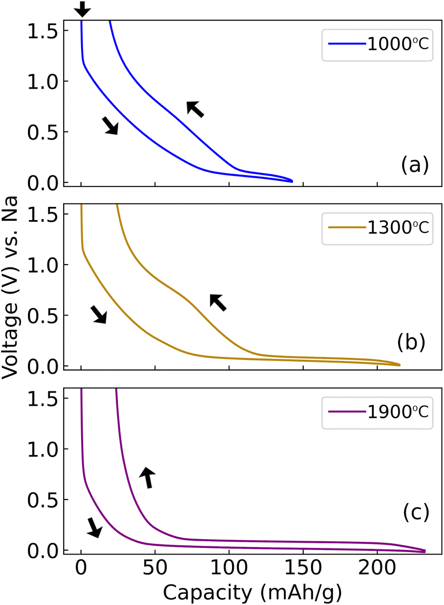
3.2 Galvanostatic cycling
To check the consistency of our electrochemical analysis with previous results from the same materials,14 we performed galvanostatic cycling at 30 mA g−1. Results are shown in Fig. 4, and are comparable with characterisation results obtained previously at the same C-rate,14 even with a different electrolyte composition. The irreversible loss of capacity during the first cycle generally decreases with increasing sample synthesis temperature (Tsynth), consistent with the sample surface area decreasing at higher Tsynth. | ||
| Fig. 4 Galvanostatic cycles performed at 30 mA g−1 cycle rate, with Ecut = 5 mV. The synthesis temperature of each hard carbon is indicated in the legend. Data for synthesis temperature 1000–1500 °C are shown in the top panels while data for synthesis temperature 1500–1900 °C are shown in the lower panels. Left column: first cycle; right column: second cycle. Arrows indicate the start point and the direction of each set of cycles. | ||
Different features are observed during the first sodiation cycle, which show a trend with synthesis temperature: Tsynth = 1000 °C shows no marked features, Tsynth = 1300–1500 °C show a plateau at about 1.2 V, while Tsynth = 1700–1900 °C show a similar plateau at 1.2 V and an additional one at 0.7 V. The 1.2 V plateau can be attributed to PC decomposition46 while the 0.7 V plateau is attributable to FEC decomposition.47 The trend in the first cycle features with Tsynth possibly results from different proportions of oxygenated groups at the hard carbon surfaces and the morphological trends highlighted in Table 4, which could influence the SEI formation mechanism in the PC/FEC electrolyte. However, further analysis of these trends is beyond the scope of the present work, with all subsequent analysis being performed after the first cycle.
There is significantly lower irreversible capacity loss on the second cycle. The second cycle capacity increases with Tsynth between 1000–1500 °C, but decreases substantially between 1500–1900 °C. It was proposed that the capacity decrease between 1500–1900 °C results from a decreasing interlayer carbon spacing d(002) (shown in Table 4), inhibiting sodium diffusion at high Tsynth.14 It is therefore informative to characterise the hard carbons at slower cycle rate. Data at 10 mA g−1 cycle rate are in Fig. 5, which were also terminated at lower Ecut = −20 mV.
 | ||
| Fig. 5 Galvanostatic cycles performed at 10 mA g−1 cycle rate, with Ecut = −0.02 V. The second cycle is shown. The synthesis temperature of each hard carbon is indicated in the legend. Arrows indicate the start point and the direction of each set of cycles. | ||
Comparing Fig. 4c and 5a, b (Tsynth = 1000 °C and 1300 °C), it is observed that the capacity value obtained is practically unaffected by the slower cycle rate and lower Ecut value in Fig. 5a and b. However, at Tsynth = 1900 °C (Fig. 5c), the capacity obtained is significantly greater: increasing from approximately 130 mA h g−1 from the second cycle at 30 mA g−1 cycle rate (with Ecut = 5 mV), to approximately 230 mA h g−1 at 10 mA g−1 (with Ecut = −20 mV). At a measured cell voltage of 5 mV, the capacity at 10 mA g−1 rate is 185 mA h g−1, indicating that an additional ≈45 mA h g−1 capacity is accessed in between 5 mV and −20 mV. The capacity of sample Tsynth = 1900 °C is, therefore, especially sensitive to Ecut as well as the cycle rate.
A more comprehensive study of the effect of cycle rate in the range 15 mA g−1, 10 mA g−1 and 7.5 mA g−1 was performed. The full set of results is presented in the ESI, Fig. S1.† Very subtle differences in the voltage responses were observed between 15 mA g−1 and 10 mA g−1 cycle rate, while almost no difference was observed between 10 and 7.5 mA g−1. Therefore, for entropy profiling characterisation a discharge (sodiation) rate of 10 mA g−1 was chosen as a good compromise between throughput and accuracy.
3.3 Entropy profiling
The analysis presented in the previous section revealed that the electrochemical properties of some of hard carbons were sensitive to cycle rate above 10 mA g−1. Part of this influence can be attributed to the different ohmic drop resulting from the different imposed currents, shifting the curves up or down on a voltage axis. Because galvanostatic profiles of hard carbons are terminated in a voltage plateau, these shifts have significant implications for the measured capacity.A straightforward solution to remove these ambiguities is to perform GITT measurements, recording the OCV with zero external current and therefore no imposed ohmic drop. In addition, temperature variation can be applied during the OCV relaxation transients, as described in Section 2.4. The OCV is shown in Fig. 6a as a function of the capacity for the five different hard carbons in the study, prepared with Tsynth = 1000–1900 °C. By numerically differentiating the raw data in Fig. 6a, dQ/dV was obtained, where the key features are shown in Fig. 6b.
 | ||
| Fig. 6 Results of GITT measurements at the end of each OCV relaxation step, obtained from galvanostatic discharge (sodiation) pulses. The legend indicates the synthesis temperature, Tsynth, in both panels. (a) OCV as a function of capacity; (b) dQ/dV results, where the voltage axis is on the same scale as (a). | ||
The OCV response in Fig. 6a reveals an increase in capacity between Tsynth = 1000–1500 °C. For samples synthesised at Tsynth = 1700 °C and Tsynth = 1900 °C, capacities are comparable in value, but both values are markedly lower than that of the Tsynth = 1500 °C, indicating a change in behaviour between Tsynth = 1500 °C and Tsynth = 1700 °C similar to that discussed in the previous section.
Fig. 6a and b are shown on the same voltage axis. Therefore, the dQ/dV peak maximum in Fig. 6b corresponds to the steepest point of the voltage plateau in Fig. 6a. The peak maximum shifts systematically to less positive voltage with increasing Tsynth, indicating that the plateau varies likewise with Tsynth. Additionally, the peak becomes narrower with increasing Tsynth, i.e. the plateau becomes steeper. The voltage of the peak maximum, and the full-width half-maximum (FWHM) of the peak are shown in Table 5. The trend is in line with dQ/dV measurements previously reported by Kubota et al.17 The trends in dQ/dV peak position and width are indicative of changes to the energetics of the sodiation process inside the pores dependent on pore size, which will be discussed shortly.
| Synthesis temp. Tsynth (°C) | Q expt (mA h g−1) | Q max (mA h g−1) | Peak max. (V vs. Na) | FWHM (mV) |
|---|---|---|---|---|
| 1000 | 117 | 161 | 0.062 | 89 |
| 1300 | 315 | 341 | 0.059 | 50 |
| 1500 | 403 | 474 | 0.052 | 44 |
| 1700 | 260 | 277 | 0.029 | 34 |
| 1900 | 254 | 276 | 0.024 | 32 |
The left hand column of Fig. 7 shows the experimental partial molar enthalpy, entropy, and OCV, where the x scale was determined from eqn (4). The thermodynamic curves were fitted to the BW model using the interaction parameters within the model as fitting parameters (c.f. the ESI† and ref. 30 for full details of the automated fitting procedure) and results of that procedure are shown on the right hand side of Fig. 7. The full set of interaction parameter values resulting from the fit is shown in Table S1.† In the insets of Fig. 7a and d, the partial molar enthalpy is shown over a narrower energetic range than the main figure.
 | ||
| Fig. 7 Left column: experimental results obtained during entropy profiling. Right column: corresponding two level simulation results. (a, d) Partial molar enthalpy (with narrower energy scale shown in the insets); (b, e) partial molar entropy; (c, f) open circuit voltage (OCV). The x axis corresponds to the overall sodium concentration in the interlayers and nanopores, normalised to the theoretical maximum capacity obtained from the model (details in the main text). The legend refers to the pyrolysis temperature, Tsynth, of each hard carbon. The features denoted A and B are described in the main text. | ||
In Fig. 7c, the voltage slope shifts systematically to lower sodium concentration, x, with increasing synthesis temperature, Tsynth. This trend indicates that the fraction of available interlayer sites decreases with increasing Tsynth, and hence the fraction of available nanopore sites increases. It is also seen that the sloping part of the OCV curve is driven by the energetics of sodiation in the interlayers, because the maximum voltage in the sloping region is almost the same as the maximum in −ΔH (Fig. 7a).
In the partial molar entropy curve (Fig. 7b), TΔS is large and positive for low x values, indicating that the interlayer sites are randomly filled with Na ions. In each of the curves for different Tsynth, there is a local minimum and maximum in TΔS, also clearly visible in the simulation result, Fig. 7e. The minimum and maximum of each curve, labelled A and B, shift to lower x with higher Tsynth. As shown in our previous study for a single hard carbon,30 prior to turning point A, only the interlayer sites are filled with Na ions. Turning point A corresponds to the onset of quasi-metallic sodium insertion into the nanopores, with interlayer and nanopore sites filled at the same time at this sodium concentration. On the other hand, by turning point B nearly all the interlayer sites are filled with Na ions, and for x greater than the maximum B, the remaining Na species fill the nanopores. This finding is therefore consistent with the transition between interlayer and nanopore filling shifting to lower x with increasing Tsynth.
A systematic trend is observed in the insets of Fig. 7a and d, indicating trends in the energetics of the nanopore filling with Tsynth. For Tsynth = 1000 °C, the experimental curve does not indicate a minimum in −ΔH, whereas the other samples do show a minimum, whose value decreases in magnitude with increasing Tsynth. The x value of the minimum coincides approximately with turning point B from the partial molar entropy curve, indicating that the interactions after −ΔH minimum are dominated by sodiation of the nanopores. After the minimum, the curve −ΔH increases with increasing concentration, suggesting an attractive driving force to fill the nanopores with sodium. The reason for this behaviour is discussed in the next section.
3.4 Correlating energetics and pore radius
Based on the construction in Fig. 3, we perform further analysis to quantify energetic terms in eqn (17). When all of the available sites in the nanopores are filled (that is, n2 = 1), the nanopore energetic term is given by
  , where ε2 and g2 were determined from the BW model above. Eqn (17) suggests that
  is proportional to 1/ravg, and this relationship is plotted in Fig. 8.
 | ||
Fig. 8 Nanopore energy term  as a function of 1/ravg, where ravg is the nanopore radius determined from small-angle X-ray scattering (SAXS). The legend refers to the pyrolysis temperature of each hard carbon. Eqn (17) is shown again inside the figure; directly beneath it, numerical parameters obtained from the line of best fit are shown. as a function of 1/ravg, where ravg is the nanopore radius determined from small-angle X-ray scattering (SAXS). The legend refers to the pyrolysis temperature of each hard carbon. Eqn (17) is shown again inside the figure; directly beneath it, numerical parameters obtained from the line of best fit are shown. | ||
For ρV, we assume the bulk body-centred cubic packing density of ρV = 25.5 atoms per nm.48 The lowest energy surface of Na is (110),49 which has a packing density of ρS = 7.7 atoms per nm. The only unknowns in eqn (17) are then εb and εs, which can be obtained by linear regression, with eqn (17) and the resulting fitting parameters shown in Fig. 8. The linear relationship between  and 1/ravg suggests that ρV, ρS, εb and εs do not strongly vary with the size of the nanopores. The intercept of the graph with the
  axis is −0.0045 eV per site, i.e. εb = −0.0045 eV. Therefore, sodium is inserted or removed from the pore interior with very similar energetics to bulk sodium, consistent with previous prior descriptions of sodium deposition in pores in a “quasi-metallic” state.9,13
From eqn (17), it is found that the gradient of the line obtained from linear regression is given by
 | (18) |
Sodiation therefore proceeds with a more negative average binding energy term (i.e. at higher voltage) in nanopores of smaller size due to the greater proportion of surface to interior sites available, which means that the εs term affects the energetics more than εb. As the pore size increases, the average binding term of all nanopore sites becomes less attractive and hence the cell voltage approaches metallic sodium. The 1/ravg scaling of the average sodium binding term emerges from the surface/volume ratio of the pores. Notably, this scaling is not dependent on the pore geometry, since the same relationship would result from assuming spherical or cylindrical pores, just with a pore shape dependent pre-factor in eqn (18).
The same result also strongly suggests a mechanism for the relationship between the sodium concentration in the nanopores and the cell voltage. With εs < 0, there is a driving force for sodium to be adsorbed to the carbon pore walls as a single layer before deposition of the second layer proceeds. Deposition of a single layer of adsorbate at potentials positive of the formal reduction potential of the metal has been well studied in other systems and is known as underpotential deposition (UPD),50,51 which has been extensively utilised in surface science and electrocatalysis to modify and characterise planar systems and nanoparticles. In UPD systems, favourable interactions between the metal adlayer and the substrate underneath allow 2D formation of one adlayer of the adsorbate. This situation is shown in Fig. 9a. UPD on nanoparticles has been found to be less favourable than the analogous planar systems,52 because the nanoparticle curvature destabilises the adsorbate–substrate interaction. The present results suggest the opposite situation: the curvature inside a nanopore leads to a more favourable adsorbate–substrate interaction.
 | ||
| Fig. 9 Illustration of variable sodium concentration inside a nanopore. (a) Deposition of the first layer of sodium inside the nanopore, facilitated by a favourable interaction between the sodium adlayer and the carbon substrate. The surface area of the sodium deposit is shown with a dashed line. The minimum radius of the cross-section of the sodium surface is r1. (b) Deposition of a fresh, second layer of sodium. The freshly-formed sodium surface has a lower surface area relative to the structure shown in (a). The new minimum radius of curvature is r2. | ||
Subsequent sodium deposition in the pores would likely occur in a layer-by-layer mode, to minimise the surface area of the deposit and hence minimise the surface energy. Fig. 9b shows that deposition of a second, fresh sodium layer inside the pore would lead to a decrease in surface area. The radius of curvature of the deposit also decreases. Since Fig. 8 implies a relationship between the pore radius of curvature and the nanopore interaction term  , the decrease in radius from deposition of the second layer would lead to an increased attraction, which is consistent the change in −ΔH with sodium concentration (Fig. 7a). This proposed mechanism of sodium deposition is also consistent with the attractive interactions determined from the dQ/dV peak half widths (Fig. 6b).
The analysis above is based on a constant value of εs; however, εs might vary across the carbon surface dependent on the local morphology. DFT calculations on graphene surfaces with different point defects indeed suggest that sodium deposition near oxygenated defects is more favourable than on pristine graphene.14,53 Morever, structural defects such as 5 or 7-membered carbon rings may contribute to the curvature of the graphene layers,54 and these defects may or may not be decorated with oxygen. Each of these defects would have a different local sodium binding energy. Samples synthesised at low Tsynth showed higher oxygen content, and the dQ/dV peak half width was wider with lower Tsynth (Table 5). In other systems, it has been shown that higher defect concentrations disrupt ordering of guest ions or adlayers, which is correlated with wider dQ/dV and voltammetric peaks.33,55 While surface heterogeneity was neglected in the present work for reasons of computational tractability, it is an additional factor that could explain the increased peak width with decreasing sample synthesis temperature. A more advanced model incorporating surface heterogeneity is currently under development.
It should be noted that a pore enclosed between two graphene layers, which has a slit-like morphology, is the simplest possible that can result. These pores have been observed in HR-TEM experiments. In all the hard carbons, there would be a distribution of pore sizes, with some domains enclosed between three or more graphene layers, whose shape would be expected to tend to a cylinder as the number of enclosing graphene layers increases. A fraction of cylindrical pores would lead to a numerically different value of εs (slightly higher in absolute value) but the nanopore energetic term  would still scale inversely with the pore radius of curvature, R. Also, the fact that this relationship is preserved across the entire range of synthesised hard carbons suggests that any distribution in pore shape morphology remains constant for all the hard carbons, and it is merely the average pore size that is altered by the synthesis temperature.
The growth mode of sodium in hard carbon has previously been reported in the form of clusters. While the present results suggest that the thermodynamically-favoured growth mode of the first 1–2 layers might be layer-by-layer, it is possible that the interaction becomes weaker with layer thickness, leading to a switch to 3D growth in a manner similar to Stranski–Krastanov growth. Additionally, the growth mode of sodium might be different under dynamic galvanostatic conditions compared with the slow GITT-type experiments used in the present work. Under certain C-rates and pore architectures, metastable cluster formation might occur.
Further, it is worth noting that the analysis above assumes that the average pore size of pristine hard carbon measured by SAXS corresponds to the size during cycling of the electrode material. It may be that some changes in the hard carbon material are experienced during and after the first galvanostatic cycle resulting from the SEI formation process. Therefore, as an outlook from this work, it would be worthwhile to examine possible changes to the average hard carbon pore size during galvanostatic cycling or GITT with techniques such as operando SAXS or small-angle neutron scattering (SANS).
4 Conclusions
In this work we examined the effects of systematic hard carbon structure variation on the entropy and energetics of sodium insertion. We can summarise the main findings as follows:• The average binding energy of sodium inside the nanopores becomes systematically weaker (less negative) as the pore radius of curvature increases. Hence, the cell voltage of the plateau gets closer to metallic sodium with increasing pore size. This is the first direct evidence, relying on experimental measurements and calculations, of a mechanism linking the curvature of the disordered graphene layers to the energetics of sodiation into the nanopores.
• For all hard carbons, pronounced entropy features were observed that cannot be detected by conventional voltage-capacity measurement. These features are ascribed to a transition between filling of sodium in the interlayers, to filling of the nanopores. The transition point shifted to a lower sodium filling fraction with increasing nanopore size. Thus, we can more accurately track and quantify sodium occupation in the disordered interlayers versus the nanopores.
• The work has implications for materials design/discovery. Our work demonstrates that the key variable to tune the nanopore insertion voltage is the curvature in the disordered carbon layers. Small pores will result in a smaller curvature radius and hence a higher nanopore voltage. While resulting in a lower full cell capacity, a plateau relatively far away from the voltage of metallic sodium might be advantageous for cell safety and longevity particularly when cycling at higher rate. However, for lower rate applications, larger pores might be preferable, in which the energetically-competitive sites for sodium insertion within the nanopores might create a buffer against sodium dendrite formation.
• The work suggests new strategies for best practice characterisation of porous insertion materials such as hard carbons. Use of GITT and OCV-based methods (even at constant temperature) should become more standard in the field and complementary to more commonly used galvanostatic methods. For hard carbon in particular, the low-lying plateau is very sensitive to structurally-dependent overpotentials. By design, OCV measurements remove these ambiguities and may be more practical to implement than three-electrode arrangements.
• Our model helps understand the average local structure of macroscopically complex systems like hard carbons, and the implications of that local structure on the energetics of pore filling. Equally, the same methodology will undoubtedly shed light on related systems of interest for energy storage/conversion. For example, determining the energetics of insertion of sodium and related metals into monolithic metal–organic frameworks (MOFs) would be a natural next step.
Author contributions
M. P. Mercer: Conceptualisation, Methodology, Software, Validation, Formal analysis, Investigation, Data Curation, Writing – Original draft, Writing – Review & Editing, Visualisation, Supervision, Project administration, Funding acquisition. M. Nagarathinam: Resources, Writing – Review & Editing, Project administration, Supervision. M. Gavilán-Arriazu: Methodology, Writing – Review & Editing. A. Binjrajka: Software, Investigation, Validation, Writing – Review & Editing. S. Panda: Software, Visualisation, Writing – Review & Editing. H. Au: Resources, Writing – Review & Editing. M. Crespo-Ribadeneyra: Resources, Writing – Review & Editing. M.-M. Titirici: Resources, Writing – Review & Editing. E. P. M. Leiva: Conceptualisation, Writing – Review & Editing, Funding acquistion. H. E. Hoster: Conceptualisation, Resources, Writing – Review & Editing, Funding acquisition.Conflicts of interest
There are no conflicts to declare.Acknowledgements
M. P. M., M. N. and H. E. H. thank the Faraday Institution (https://www.faraday.ac.uk; EP/S003053/1), grant number FIRG025, for funding. M. P. M. also acknowledges support of the High End Computing facility at Lancaster University. E. M. G.-A. acknowledges grant FONCYT PICT-2020-SERIEA-00707. A. B. is grateful to the Faraday Institution for FUSE internship funding. H. A. thanks the Faraday Institution (https://www.faraday.ac.uk; EP/S003053/1), grant number FIRG014, for funding. M. C.-R. acknowledges the EPSRC grant EP/S018204/2 (UK-China Low Carbon Manufacturing call). M.-M. T. acknowledges funding as a Chair of Emerging Technologies from the Royal Academy of Engineering (RAEng). E. P. M. L. acknowledges grants PIP CONICET 11220200101189CO, PUE/2017 CONICET, FONCYT 2020-SERIEA-03689. We are also grateful to Dr Phoebe Allan (University of Birmingham) and Prof. Clare Grey (University of Cambridge) for discussions regarding the structural model of hard carbon.Notes and references
- J.-M. Tarascon and M. Armand, Nature, 2001, 414, 359–367 CrossRef CAS PubMed.
- H. C. Hesse, M. Schimpe, D. Kucevic and A. Jossen, Energies, 2017, 10, 2107 CrossRef.
- L. Vandepaer, J. Cloutier and B. Amor, Renew. Sust. Energ., 2017, 78, 46–60 CrossRef CAS.
- N. Tapia-Ruiz, A. R. Armstrong, H. Alptekin, M. A. Amores, H. Au, J. Barker, R. Boston, W. R. Brant, J. M. Brittain, Y. Chen, M. Chhowalla, Y.-S. Choi, S. I. R. Costa, M. C. Ribadeneyra, S. A. Cussen, E. J. Cussen, W. I. F. David, A. V. Desai, S. A. M. Dickson, E. I. Eweka, J. D. Forero-Saboya, C. P. Grey, J. M. Griffin, P. Gross, X. Hua, J. T. S. Irvine, P. Johansson, M. O. Jones, M. Karlsmo, E. Kendrick, E. Kim, O. V. Kolosov, Z. Li, S. F. L. Mertens, R. Mogensen, L. Monconduit, R. E. Morris, A. J. Naylor, S. Nikman, C. A. O'Keefe, D. M. C. Ould, R. G. Palgrave, P. Poizot, A. Ponrouch, S. Renault, E. M. Reynolds, A. Rudola, R. Sayers, D. O. Scanlon, S. Sen, V. R. Seymour, B. Silván, M. T. Sougrati, L. Stievano, G. S. Stone, C. I. Thomas, M.-M. Titirici, J. Tong, T. J. Wood, D. S. Wright and R. Younesi, J. Phys. Energy, 2021, 3, 031503 CrossRef CAS.
- F. Xie, Z. Xu, Z. Guo and M.-M. Titirici, Prog. Energy, 2020, 2, 042002 CrossRef.
- A. Metrot, D. Guerard, D. Billaud and A. Herold, Synth. Met., 1980, 1, 363–369 CrossRef CAS.
- D. A. Stevens and J. R. Dahn, J. Electrochem. Soc., 2000, 147, 1271 CrossRef CAS.
- D. A. Stevens and J. R. Dahn, J. Electrochem. Soc., 2001, 148, A803 CrossRef CAS.
- J. M. Stratford, A. K. Kleppe, D. S. Keeble, P. A. Chater, S. S. Meysami, C. J. Wright, J. Barker, M.-M. Titirici, P. K. Allan and C. P. Grey, J. Am. Chem. Soc., 2021, 143, 14274–14286 CrossRef CAS PubMed.
- N. Sun, Z. Guan, Y. Liu, Y. Cao, Q. Zhu, H. Liu, Z. Wang, P. Zhang and B. Xu, Adv. Energy Mater., 2019, 9, 1901351 CrossRef.
- N. Sun, J. Qiu and B. Xu, Adv. Energy Mater., 2022, 12, 2200715 CrossRef CAS.
- R. Zhao, N. Sun and B. Xu, Small Structures, 2021, 2, 2100132 CrossRef CAS.
- J. M. Stratford, P. K. Allan, O. Pecher, P. A. Chater and C. P. Grey, Chem. Commun., 2016, 52, 12430–12433 RSC.
- H. Au, H. Alptekin, A. C. S. Jensen, E. Olsson, C. A. O'Keefe, T. Smith, M. Crespo-Ribadeneyra, T. F. Headen, C. P. Grey, Q. Cai, A. J. Drew and M.-M. Titirici, Energy Environ. Sci., 2020, 13, 3469–3479 RSC.
- M. Anji Reddy, M. Helen, A. Groß, M. Fichtner and H. Euchner, ACS Energy Lett., 2018, 3, 2851–2857 CrossRef CAS.
- J. S. Weaving, A. Lim, J. Millichamp, T. P. Neville, D. Ledwoch, E. Kendrick, P. F. McMillan, P. R. Shearing, C. A. Howard and D. J. Brett, ACS Appl. Energy Mater., 2020, 3, 7474–7484 CrossRef CAS.
- K. Kubota, S. Shimadzu, N. Yabuuchi, S. Tominaka, S. Shiraishi, M. Abreu-Sepulveda, A. Manivannan, K. Gotoh, M. Fukunishi, M. Dahbi and S. Komaba, Chem. Mater., 2020, 32, 2961–2977 CrossRef CAS.
- D. Chen, W. Zhang, K. Luo, Y. Song, Y. Zhong, Y. Liu, G. Wang, B. Zhong, Z. Wu and X. Guo, Energy Environ. Sci., 2021, 14, 2244–2262 RSC.
- Y. Pan, Y. Zhang, B. S. Parimalam, C. C. Nguyen, G. Wang and B. L. Lucht, J. Electroanal. Chem., 2017, 799, 181–186 CrossRef CAS.
- K. Schutjajew, T. Tichter, J. Schneider, M. Antonietti, C. Roth and M. Oschatz, Phys. Chem. Chem. Phys., 2021, 23, 11488–11500 RSC.
- R. Väli, A. Jänes and E. Lust, J. Electrochem. Soc., 2017, 164, E3429 CrossRef.
- C. Bommier, T. W. Surta, M. Dolgos and X. Ji, Nano Lett., 2015, 15, 5888–5892 CrossRef CAS PubMed.
- Z. Jian, C. Bommier, L. Luo, Z. Li, W. Wang, C. Wang, P. A. Greaney and X. Ji, Chem. Mater., 2017, 29, 2314–2320 CrossRef CAS.
- T. Chen, X. Liu, L. Niu, Y. Gong, C. Li, S. Xu and L. Pan, Inorg. Chem. Front., 2020, 7, 567–582 RSC.
- H. Alptekin, H. Au, E. Olsson, J. Cottom, A. C. Jensen, T. F. Headen, Q. Cai, A. J. Drew, M. Crespo Ribadeneyra and M.-M. Titirici, Adv. Mater. Interfac., 2022, 9, 2101267 CrossRef CAS.
- G. Kamath, R. W. Cutler, S. A. Deshmukh, M. Shakourian-Fard, R. Parrish, J. Huether, D. P. Butt, H. Xiong and S. K. R. S. Sankaranarayanan, J. Phys. Chem. C, 2014, 118, 13406–13416 CrossRef CAS.
- J. Fondard, E. Irisarri, C. Courrèges, M. R. Palacin, A. Ponrouch and R. Dedryvère, J. Electrochem. Soc., 2020, 167, 070526 CrossRef CAS.
- A. Ponrouch, E. Marchante, M. Courty, J.-M. Tarascon and M. R. Palacín, Energy Environ. Sci., 2012, 5, 8572–8583 RSC.
- K. Westman, R. Dugas, P. Jankowski, W. Wieczorek, G. Gachot, M. Morcrette, E. Irisarri, A. Ponrouch, M. R. Palacín, J.-M. Tarascon and P. Johansson, ACS Appl. Energy Mater., 2018, 1, 2671–2680 CrossRef CAS.
- M. P. Mercer, S. Affleck, E. M. Gavilán-Arriazu, A. A. Zülke, P. A. Maughan, S. Trivedi, M. Fichtner, A. Reddy Munnangi, E. P. M. Leiva and H. E. Hoster, ChemPhysChem, 2022, 23, e202100748 CrossRef CAS PubMed.
- K. Pan, H. Lu, F. Zhong, X. Ai, H. Yang and Y. Cao, ACS Appl. Mater. Interfaces, 2018, 10, 39651–39660 CrossRef CAS PubMed.
- M. P. Mercer, M. Otero, M. Ferrer-Huerta, A. Sigal, D. E. Barraco, H. E. Hoster and E. P. Leiva, Electrochim. Acta, 2019, 324, 134774 CrossRef CAS.
- S. Schlueter, R. Genieser, D. Richards, H. E. Hoster and M. P. Mercer, Phys. Chem. Chem. Phys., 2018, 20, 21417–21429 RSC.
- M. P. Mercer, C. Peng, C. Soares, H. E. Hoster and D. Kramer, J. Mater. Chem. A, 2021, 9, 492–504 RSC.
- P. J. Osswald, M. del Rosario, J. Garche, A. Jossen and H. E. Hoster, Electrochim. Acta, 2015, 177, 270–276 CrossRef CAS.
- M. E. Wojtala, A. A. Zülke, R. Burrell, M. Nagarathinam, G. Li, H. E. Hoster, D. A. Howey and M. P. Mercer, J. Electrochem. Soc., 2022, 169, 100527 CrossRef.
- K. Gotoh, T. Yamakami, I. Nishimura, H. Kometani, H. Ando, K. Hashi, T. Shimizu and H. Ishida, J. Mater. Chem. A, 2020, 8, 14472–14481 RSC.
- A. Rinaldi, O. Wijaya and H. Hoster, ChemElectroChem, 2016, 3, 1944–1950 CrossRef CAS.
- J. Hedman, R. Mogensen, R. Younesi and F. Björefors, ACS Appl. Energy Mater., 2022, 5, 6219–6227 CrossRef CAS.
- E. Markevich, M. Levi and D. Aurbach, J. Electroanal. Chem., 2005, 580, 231–237 CrossRef CAS.
- Z.-E. Yu, Y. Lyu, Y. Wang, S. Xu, H. Cheng, X. Mu, J. Chu, R. Chen, Y. Liu and B. Guo, Chem. Commun., 2020, 56, 778–781 RSC.
- Z. Wang, X. Feng, Y. Bai, H. Yang, R. Dong, X. Wang, H. Xu, Q. Wang, H. Li, H. Gao and C. Wu, Adv. Energy Mater., 2021, 11, 2003854 CrossRef CAS.
- K. C. Wasalathilake, G. A. Ayoko and C. Yan, Carbon, 2018, 140, 276–285 CrossRef CAS.
- C. Bommier, X. Ji and P. A. Greaney, Chem. Mater., 2019, 31, 658–677 CrossRef CAS.
- M. Levi and D. Aurbach, Electrochim. Acta, 1999, 45, 167–185 CrossRef CAS.
- R. Väli, A. Jänes, T. Thomberg and E. Lust, J. Electrochem. Soc., 2016, 163, A1619 CrossRef.
- S. Komaba, T. Ishikawa, N. Yabuuchi, W. Murata, A. Ito and Y. Ohsawa, ACS Appl. Mater. Interfaces, 2011, 3, 4165–4168 CrossRef CAS PubMed.
- W. Adlhart, G. Fritsch, A. Heidemann and E. Luescher, Phys. Lett. A, 1974, 47, 91–92 CrossRef CAS.
- J. Wang and S.-Q. Wang, Surf. Sci., 2014, 630, 216–224 CrossRef CAS.
- E. Herrero, L. J. Buller and H. D. Abruña, Chem. Rev., 2001, 101, 1897–1930 CrossRef CAS PubMed.
- D. Kolb, M. Przasnyski and H. Gerischer, J. Electroanal. Chem., 1974, 54, 25–38 CrossRef CAS.
- O. A. Oviedo, P. Velez, V. A. Macagno and E. P. M. Leiva, Surf. Sci., 2015, 631, 23–34 CrossRef CAS.
- H. Alptekin, H. Au, A. C. Jensen, E. Olsson, M. Goktas, T. F. Headen, P. Adelhelm, Q. Cai, A. J. Drew and M.-M. Titirici, ACS Appl. Energy Mater., 2020, 3, 9918–9927 CrossRef CAS.
- T. W. Surta, E. Koh, Z. Li, D. B. Fast, X. Ji, P. A. Greaney and M. R. Dolgos, Adv. Energy Mater., 2022, 12, 2200647 CrossRef CAS.
- M. P. Mercer, S. Finnigan, D. Kramer, D. Richards and H. E. Hoster, Electrochim. Acta, 2017, 241, 141–152 CrossRef CAS.
Footnotes |
| † Electronic supplementary information (ESI) available. See DOI: https://doi.org/10.1039/d2ta09406a |
| ‡ Present address: Department of Chemistry, University of Edinburgh, Edinburgh, EH8 9YL, UK. |
| § Present address: The Blackett Laboratory, Imperial College London, South Kensington, SW7 2AZ, UK. |
| This journal is © The Royal Society of Chemistry 2023 |