
 Open Access Article
 This Open Access Article is licensed under a
 Creative Commons Attribution 3.0 Unported Licence
A comparative analysis of the influence of hydrofluoroethers as diluents on solvation structure and electrochemical performance in non-flammable electrolytes†
Wessel W. A.
van Ekeren
 a,
Marcelo
Albuquerque
a,
Gustav
Ek
a,
Ronnie
Mogensen
a,
William R.
Brant
a,
Luciano T.
Costa
b,
Daniel
Brandell
a and
Reza
Younesi
*a
a,
Marcelo
Albuquerque
a,
Gustav
Ek
a,
Ronnie
Mogensen
a,
William R.
Brant
a,
Luciano T.
Costa
b,
Daniel
Brandell
a and
Reza
Younesi
*a
aDepartment of Chemistry-Ångström Laboratory, Uppsala University, Box 538, Uppsala SE-751 21, Sweden. E-mail: reza.younesi@kemi.uu.se
bMolMod-CS, Physical Chemistry Department, Institute of Chemistry, Fluminense Federal University, Campus Valonguinho, Niterói-RJ, CEP 24020-141s, Brazil
First published on 23rd January 2023
Abstract
To enhance battery safety, it is of utmost importance to develop non-flammable electrolytes. An emerging concept within this research field is the development of localized highly concentrated electrolytes (LHCEs). This type of liquid electrolyte relies on the concept of highly concentrated electrolytes (HCEs), but possesses lower viscosity, improved conductivity and reduced costs due to the addition of diluent solvents. In this work, two different hydrofluoroethers, i.e., bis(2,2,2-trifluoroethyl) ether (BTFE) and 1,1,2,2-tetrafluoroethyl 2,2,3,3-tetrafluoropropyl ether (TTE), are studied as diluents in a phosphate-based non-flammable liquid electrolyte. These two solvents were added to a highly concentrated electrolyte of 3.0 M lithium bis(fluorosulfonyl)imide (LiFSI) in triethyl phosphate (TEP) whereby the salt concentration was diluted to 1.5 M. The solvation structures of the HCE and LHCE were studied by means of Raman spectroscopy and Nuclear Magnetic Resonance (NMR) spectroscopy, where the latter was shown to be essential to provide more detailed insights. By using molecular dynamics simulations, it was shown that a highly concentrated Li+–TEP solvation sheath is formed, which can be protected by the diluents TTE and BTFE. These simulations have also clarified the energetic interaction between the components in the LHCE, which supports the experimental results from the viscosity and the NMR measurements. By performing non-covalent interaction analysis (NCI) it was possible to show the main contributions of the observed chemical shifts, which indicated that TTE has a stronger effect on the solvation structure than BTFE. Moreover, the electrochemical performances of the electrolytes were evaluated in half-cells (Li|NMC622, Li|graphite), full-cells (NMC622|graphite) and Li metal cells (Li|Cu). Galvanostatic cycling has shown that the TTE based electrolyte performs better in full-cells and Li-metal cells, compared to the BTFE based electrolyte. Operando pressure measurements have indicated that no significant amount of gases is evolved in NMC622|graphite cells using the here presented LHCEs, while a cell with 1.0 M LiFSI in TEP displayed clear formation of gaseous products in the first cycles. The formation of gaseous products is accompanied by solvent co-intercalation, as shown by operando XRD, and quick cell failure. This work provides insights on understanding the solvation structure of LHCEs and highlights the relationship between electrochemical performance and pressure evolution.
1 Introduction
The global demand for energy storage devices is expected to increase rapidly in the next decades. If batteries do not become safer, the number of fires originating from battery failure will also scale proportionately. Currently, most commercial batteries consist of a flammable organic liquid electrolyte. To enhance battery safety, the development of non-flammable electrolytes has become ever more important.1 While the use of solid-state electrolytes is promising, they currently lack either ionic conductivity (polymer electrolytes) or have poor interfacial contacts (ceramic electrolytes).2 Therefore, there is an interest to develop non-flammable liquid electrolytes, given that they improve the safety and do not compromise electrochemical performance. Another critical aspect in the development of battery electrolytes is their extended electrochemical window to fulfill the demand of high energy batteries, enabling their use with electrodes operating at extreme potentials (such as Li-metal and high-voltage cathodes). One promising approach towards non-flammable electrolytes is to use alkyl phosphates as electrolyte solvents, due to their radical scavenging ability.3 However, previous work has shown that the alkyl phosphates are not compatible with carbonaceous anodes.4 Several approaches have been demonstrated to overcome this issue, such as using high concentrations of non-combustible salts and using electrolyte additives or salts forming passive interfacial layers.5–7 Recent studies have revealed that electrolytes with a high salt concentration form a solvation structure with a minimum number of free solvent molecules, whereby the reactivity of the solvent with both the anode and the cathode material is effectively suppressed.8,9 Also, due to enhanced interaction between anions and Li+, the electron density will shift from the anion to the Li+ cation. This causes a preferred reduction of the anion, resulting in an inorganic anion-derived SEI.10 The concept of high salt concentration electrolytes has shown to lead to high coulombic efficiencies in Li-metal batteries.11 However, the high concentrations of salt also mean high viscosity and increased costs.To reduce the overall salt concentration, and thereby the costs of the electrolyte, an inert diluent can be added to the highly concentrated electrolytes (HCEs) to obtain localized highly concentrated electrolytes (LHCEs).12 Such a diluent should ideally (1) have zero to minimum salt solubility, (2) be miscible with the main electrolyte solvent, (3) preserve the solvation structure (by inherent poor cation solvation capability), (4) have lower costs than other electrolyte components and (5) be non-flammable for safety.13 Ideal candidates that fulfill these requirements are hydrofluoroethers, primarily because they have low dielectric constants (low salt solubility) and low viscosities (enhanced conductivity). A solvent with a low dielectric constant does not participate in ion association in the electrolyte, so it will not interfere with the attraction of ions of opposite charge.
Molecular dynamics (MD) simulations have been extensively used to address the structural organization of ionic liquids, as well as to study the influence of salt concentration on the solvation structure and the dynamics of the electrolyte.14,15 For example, DFT-MD simulations have supported the understanding of the coordination of anions and solvents around Li+ in the highly concentrated regime of LiFSA in DMC, showing insights on contact ionic pair (CIP) and aggregate (AGG) formation.16 Furthermore, links between the anion reduction and the Li+-anion coordination have been proposed via DFT.10,17 Also, electrolyte structure and solvation energy have been estimated for highly fluorinated non-polar solvents as well as elucidation of solvent reactions of fluorinated electrolytes on a LiCoPO4 cathode surface.18,19 Combinations of NMR spectroscopy with MD simulations have also been performed in several studies.20,21 Furthermore, DFT has been employed to corroborate NMR experimental results with the interactions between atoms and molecules by applying the quantum theory of atoms in molecules (QTAIM) and non-covalent interactions (NCI) in the conformational analysis of organic molecules and both intra- and intermolecular hydrogen bonding involving fluorine.22–27 In this study these techniques are applied to understand the solvation structure of HCEs and LHCEs.
Bis(2,2,2-trifluoroethyl) ether (BTFE) and 1,1,2,2-tetrafluoroethyl 2,2,3,3-tetrafluoropropyl ether (TTE) are two examples of hydrofluoroether diluents which have been tested previously. They have a dielectric constant of 4.4 and 6.2, respectively.28,29 Table S1 in the ESI† provides an overview of the electrolytes that have been studied in this and previous work. LHCEs obtained with BTFE have mainly been studied in lithium-metal batteries while a few studies exist in lithium-ion batteries with graphite and silicon/graphite anodes.12,30–33 LHCEs with TTE have been studied in lithium-metal batteries and in lithium-ion batteries with graphite anodes.34–36 However, most of the previous studies on TTE used a flammable carbonate-based solvent and only a few studies have been performed with non-flammable solvents.37 Furthermore, very few studies exist on the application of this type of electrolyte in full-cells. In this study, BTFE and TTE are studied as diluents in a non-flammable electrolyte based on LiFSI salt and triethyl phosphate (TEP) solvent. The effects of two different diluents are (1) evaluated in terms of effectiveness to preserve the solvation structure of the HCE, (2) compared in terms of electrochemical performance in half-cells, full-cells, and Li-metal cells, and (3) analyzed in terms of electrolyte stability during formation cycles by operando pressure analysis. This work thereby provides new insights on the solvation structure of non-flammable LHCEs and the compatibility of the LHCEs in lithium-ion batteries.
2 Methods
2.1 Preparation of electrolytes
Lithium bis(fluorosulfonyl)imide (LiFSI, Solvionic, 99.9%) was dried in a vacuum oven at 120 °C for 12 hours. Prior to use, the solvents triethylene phosphate (TEP, Acros, 99.8%), bis(2,2,2)-trifluoroethyl (BTFE, Sigma-Aldrich, 98%) and 1,1,2,2-tetrafluoroethyl 2,2,3,3-tetrafluoropropyl ether (TTE, Apollo Scientific, 98%) were dried over dehydrated molecular sieves (4.0 Å) for at least 48 hours. First, a highly concentrated electrolyte (HCE) was prepared by dissolving 3.0 M LiFSI in TEP inside an argon-filled glovebox (O2 < 1 ppm and H2O < 1 ppm). Subsequently, the HCE was diluted with either BTFE or TTE to obtain respectively 1.5 M LiFSI in TEP/BTFE and 1.5 M LiFSI in TEP/TTE. The electrolyte mixtures were stirred for 24 hours or until clear solutions were obtained. After electrolyte preparation, the water content was lower than 20 ppm (10.8 ppm for 1.5 M LiFSI in TEP/BTFE and 14.2 ppm for 1.5 M LiFSI in TEP/TTE) measured by Karl Fischer titration. For the flammability experiments 1.0 M LiPF6 in ethylene carbonate (EC)![[thin space (1/6-em)]](https://www.rsc.org/images/entities/char_2009.gif) :diethyl carbonate (DEC) = 1:1 v/v (LP40) was purchased from Solvionic and used as received.
:diethyl carbonate (DEC) = 1:1 v/v (LP40) was purchased from Solvionic and used as received.
2.2 Physicochemical properties
The viscosity and density of the electrolytes were analyzed using a Lovis 2000 M/ME (Anton Paar) operating between 10 °C and 50 °C. The conductivity measurements were carried out at room temperature (20 °C) using a Mettler Toledo SevenGo Duo pro pH/ORP/Ion/Conductivity meter SG78 with an InLab 738ISM probe. Flammability tests were performed by placing a few drops of electrolyte on 10 × 1 cm glass fiber strips which were subsequently exposed to a butane flame.2.3 Raman spectroscopy
Raman spectra were obtained from a Renishaw Raman spectrometer InVia (2013) using a 785 nm laser source (laser power of 1.5 mW) and grating of 1200 lines per mm. The spectra were analyzed with the WIRE 5.4 software (Renishaw Inc.). After the spectra were collected, the baseline was subtracted and the peaks were normalized based on the highest intensity peak.2.4 Nuclear magnetic resonance (NMR) spectroscopy
The neat solvent and electrolyte NMR spectra were recorded on a 400 MHz JEOL ECZ spectrometer. Anhydrous dimethyl sulfoxide (DMSO)-d6 (99.9%) from VWR was used as a deuterated solvent and was dried with molecular sieves prior to use. To prepare the NMR samples, an outer borosilicate tube (5 mm) was filled with the DMSO-d6 reference and an inner fluorinated ethylene polypropylene (FEP) sample tube liner (3 mm) was filled with the neat solvent or electrolyte, to prevent interactions between the reference solvent and the electrolyte sample. Both tubes were closed with poly(tetrafluoroethylene) (PTFE) plugs. All NMR samples were prepared in an argon-filled glovebox (O2 < 1 ppm and H2O < 1 ppm). 1H-NMR, 7Li-NMR and 13C-NMR spectra were recorded.2.5 Molecular dynamics
Classical MD simulations were performed to analyse the solvation structure of the studied electrolytes. This analysis was done by applying the non-polarizable OPLS-AA force field approach to Newton's equations of classical motion.38 The overall potential includes the summation of all non-bonded interactions (Lennard-Jones (LJ) and Coulomb potentials), as well as the harmonic bond and angle terms, and the dihedral term. A scaling factor for both van der Waals and coulombic interactions was set to 0.5 for interactions between atoms which were separated by more than three covalent bonds. The aforementioned parameters and the topology of the system for both the ions and solvents were generated using a Python tool developed by Agilio Padua's group, ‘ff tool’.39 The systems were composed as shown in Table 1, similar to Cao et al. and Wang et al. using Packmol.9,40,41 Here, the maximum number of molecules in the simulation box was limited to about 550. To perform the molecular dynamics simulations, GROMACS version 2021.3 was used.| Solvents | Salt con. (M) | Molar ratio | N salt | N TEP | N TTE/BTFE | N total |
|---|---|---|---|---|---|---|
| TEP | 1.0 | 1:6 |
78 | 468 | — | 546 |
| 3.0 | 1:2 |
183 | 366 | — | 549 | |
| TEP/TTE | 1.0 | 1:1.2:2.2 |
125 | 150 | 275 | 550 |
| 1.2 | 1:1.2:1.6 |
145 | 174 | 232 | 551 | |
| 1.5 | 1:1.2:1.2 |
172 | 172 | 206 | 550 | |
| TEP/BTFE | 1.0 | 1:1.2:2.4 |
120 | 144 | 288 | 552 |
| 1.2 | 1:1.2:1.8 |
138 | 166 | 288 | 552 | |
| 1.5 | 1:1.2:1.4 |
162 | 162 | 227 | 551 |
Energy minimization was carried out through the conjugate gradient algorithm, where a steepest descent step was performed every ten steps. The entire equilibration phase was performed under the NpT ensemble. Firstly, a short leap-frog stochastic dynamics (SD) routine was performed for 200 ps at 300 bar and with particle velocities generated by a Maxwell distribution at 298 K.42 This step was followed by another SD for 20 ns at 1.0 bar and 298 K using a Berendsen barostat with a coupling time of 1.0 ps.43 Then, a longer production run was performed for 50 ns using Parrinello–Rahman's barostat and a velocity-rescale thermostat.44,45 The coupling times were set to 5.0 ps and 0.1 ps, respectively. Furthermore, all hydrogen bonds were kept constrained, a LINCS algorithm was used to keep the bond length fixed, and Ewald summation was used for Coulomb interactions.46,47 For all interactions, a 1.2 nm cut-off was used. The LJ potential was smoothly switched off between 1.0 and 1.2 nm. All analyses were performed using GROMACS's tools. The spatial distribution function (SDF) analysis and visualization were done from the MD trajectories using TRAVIS.48,49 Furthermore, a visual molecular dynamics (VMD) tool was used to visualize isosurfaces generated from TRAVIS’ SDF program.50 To calculate the SDF isosurfaces, the oxygen atoms (O4 and O3) and P atoms of TEP were used as the reference, as well as the N atom of FSI.
2.6 Density functional theory (DFT)
Single-point self-consistent density functional theory calculations were performed for the conventional and highly concentrated electrolytes, as well as for the LHCEs. All calculations were performed using the Head-Gordon's DF ωB97X including D3 correction, with the 6-311++G(d,p) basis set and with DFT-D3(BJ) optimized correction by Najibi and Goerigk.51–53 Those calculations were followed by geometry optimization for the salt concentrations defined in Table 1 using the 6-31G basis set. The level of theory and correction applied are commonly used in geometry optimization, non-covalent interactions, prediction of conformational energies, as well as barrier heights of transition states.54 The non-covalent interaction (NCI) analysis or reduced density gradient (RDG) method (see the description in the ESI†) was performed using the multifunctional wavefunction analyzer Multiwfn.23,55 All calculations were performed using ORCA-v.5.0.3.56,572.7 Electrochemical measurements
The operando electrochemical pressure measurements were carried out using a helium-leak tested pressure cell (PAT-Cell-Press) of El-Cell®GmbH and a Biologic potentiostat. The PAT-Cell-Press consists of a lower plunger, upper plunger and insulation sleeve which were all used as delivered by El-Cell. The plungers are made of aluminum and copper, acting as current collectors. The insulation sleeve contained a pre-dried borosilicate-glass fiber separator (Whatman®, grade GF/A, 18 mm diameter, 260 μm). The cell setup was helium-leak tested and guaranteed a maximum leakage rate of 0.3 mbar h−1. The cells were assembled with 100 mL electrolyte in an argon-filled glovebox (O2 < 1 ppm and H2O < 1 ppm). The initial stack pressure of the cells might differ slightly, because the upper lid of the cell is closed manually. After assembly the cells were placed in a climate chamber (KB53, Binder (KGmbH)) and cycled at 30 °C using a Biologic potentiostat. The cells were cycled according to 3 formation cycles at C/10 between 3.0 V and 4.2 V.The plating and stripping experiments were conducted on an Arbin laboratory cycling system, at room temperature (around 20 °C). Lithium was purchased from Cyprus Foote Minerals, had a thickness of 125 μm and was used as delivered. Lithium acted as the counter electrode and the foil was punched into disks with a diameter of 10 mm. Copper was used as the working electrode and had a diameter of 13 mm. The copper was washed with ethanol and dried overnight at 60 °C. All cells were cycled using glass fiber (GF/A Whatman®, 20 mm diameter, 160 μm thick). The plating and stripping experiments were executed according to the reservoir method, which is described in more detail elsewhere.58 A plating current density of 0.5 mA cm−2 was applied for 10 hours, followed by a stripping current density of 0.5 mA cm−2 for 10 hours. Subsequently, 0.5 mA cm−2 was applied for 4 hours (plating), which was followed by 10 cycles of 0.5 mA cm−2 for 2 hours (stripping and plating).
The electrolytes were also tested in half- and full-cell pouch configurations. The half-cells were assembled using lithium with a diameter of 10 mm and either NMC622 or graphite with a diameter of 13 mm. Prior to use, the electrodes were dried under vacuum for 12 hours. Pouch cells were assembled in an argon-filled glovebox. The galvanostatic cycling tests were performed on a LAND battery testing system (model CT2001 A), at room temperature (around 20 °C). The cells were kept at OCV for 12 hours prior to cycling to ensure proper wetting of the electrodes.
2.8 Operando X-ray diffraction
Operando synchrotron X-ray powder diffraction (SXRD) was conducted at the DanMAX beamline located at the MAX IV laboratory in Lund, Sweden. Data were collected from a regular pouch cell mounted in transmission geometry using a Dectris Pilatus3 2 M CdTe detector with a wavelength (λ) of 0.35424 Å (35 keV) as determined by LaB6 standard.3 Results and discussion
3.1 Physicochemical properties – viscosity, ionic conductivity and flammability
Fig. 1 shows the dynamic viscosity data for the studied HCE and LHCE electrolytes in the temperature range of 10–40 °C. The decrease in the viscosity is more than 10-fold when the diluent is added to HCE. The ion pairs and aggregates that are formed in the highly concentrated electrolyte increase the electrostatic interaction significantly, hence the high viscosity values. It should be noted that the viscosity of the HCE is not measured below 20 °C due to limitations in the range of the viscosity-meter (maximum viscosity is 90 mPa s). The viscosity of the TTE based electrolytes is slightly higher than for the BTFE based electrolytes. However, for both LHCEs the viscosity values were significantly reduced and therefore the wettability was enhanced. | ||
| Fig. 1 Dynamic viscosity measurements for 3.0 M LiFSI in TEP (HCE), 1.5 M LiFSI in TEP/BTFE (LHCE) and 1.5 M LiFSI in TEP/TTE (LHCE). | ||
The ionic conductivity of the electrolytes was measured at room temperature. Following the trend from the viscosity measurements, the ionic conductivity (κ) for 3.0 M LiFSI in TEP, 1.5 M LiFSI in TEP/BTFE and 1.5 M LiFSI TEP/TTE were equal to 0.5 mS cm−1, 2 mS cm−1 and 1.6 mS cm−1, respectively. The ionic conductivity for both LHCEs is slightly improved compared to the HCE, but it is still less than that of conventional electrolytes (5–10 mS cm−1), which is non-ideal in terms of electrochemical kinetics.59 These ionic conductivity values could be improved, by for instance an increase in diluent concentration. However, this might affect the electrochemical performance and thus great care in optimizing the solvent mixture is required.
In Fig. 2, the photo recordings of the flammability experiments are shown. The commercial LP40 electrolyte easily catches fire when the butane torch hits the soaked glass fiber strip, whereas both LHCEs appeared to be non-flammable, even after multiple attempts of exposing the butane flame to the soaked glass fiber. It should be mentioned that gaseous fumes were formed, which might be flammable when higher temperatures are reached. The flammability of the bulk LHCEs is negligible compared to LP40, however the gaseous fumes might still be problematic if certain temperatures are reached during battery failure.
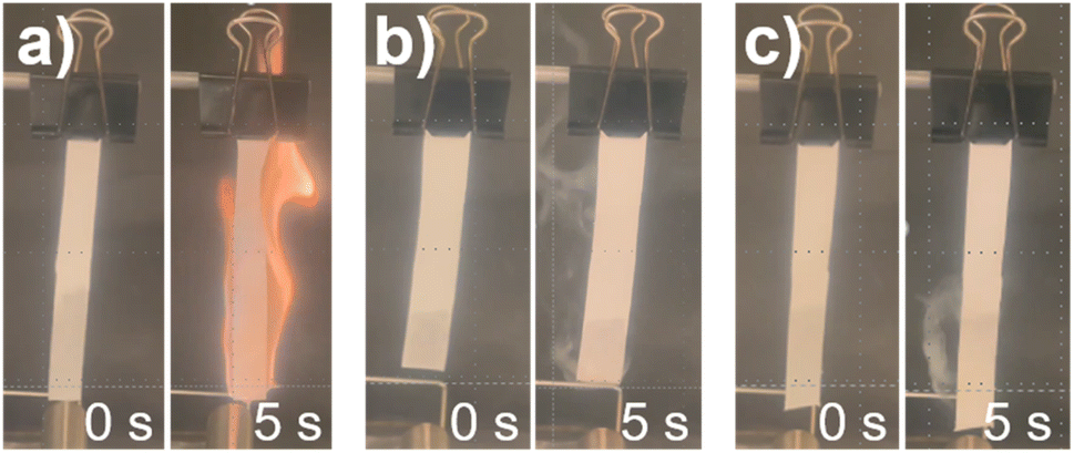 | ||
| Fig. 2 An overview of the flammability experiment. Figure (a) represents LP40, figure (b) represents 1.5 M LiFSI in TEP/BTFE and figure (c) represents 1.5 M LiFSI in TEP/TTE. | ||
3.2 Raman spectroscopy
By varying the salt concentration in electrolytes, one can alter the coordination behavior of Li+. The effect of varying the salt concentration is analyzed by Raman spectroscopy. From Fig. 3a it can be seen that the peak at 1100 cm−1, attributed to CH3 in TEP, is not shifted upon dilution. The fact that this peak does not shift tells us that dilution does not affect the solvation structure of Li+ and TEP at this particular CH3 bond, in the LHCE based on BTFE. The stretching S–O peak at 1225 cm−1 is assigned to dissolved LiFSI. When the LiFSI concentration is increased (from 1.5 M to 3.0 M), the number of FSI anions are increased accordingly and tends to enter the Li+ solvation sheath, because not all TEP solvent molecules can coordinate the Li+. This eventually leads to the formation of contact ion pairs (CIPs) and aggregates (AGGs). When the salt concentration increases, the Li+ cations tend to be fully coordinated with the solvent. In other words, less free solvent is available in the electrolyte, which also allows anions to interact with the Li+ cations and form contact ion pairs or even aggregates when the anion is coordinated to two or more cations.60 It should be mentioned that the Raman spectra do not indicate at which concentration contact ion pairs and aggregates start to be formed. Another interesting observation is the change of the peak around 1290 cm−1. This peak is attributed to the PO stretching vibration in TEP and indicates changes in the Li+–TEP coordination.61 The peak is strongly present in neat TEP, disappears in 1.0 M LiFSI in TEP, but becomes more profound in diluted 1.2 M LHCE. In a study by Yamada et al., it has been shown that the abundance of free FSI anions can be indicated by a vibration peak around 717 cm−1.62 This peak will be blue shifted to about 730 cm−1 if the anions form CIPs and AGGs. However, since the stretching P–O–(C) peak of TEP vibration is also present around 730 cm−1 the possible development of CIPs and AGGs can unfortunately not be shown for this particular electrolyte chemistry. Nevertheless, to gain a more complete insight into the solvation structure of Li+–TEP, 13C-NMR measurements were performed and are discussed in the next section.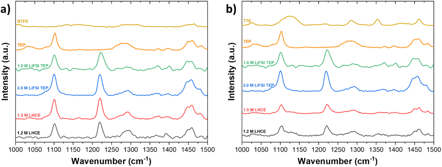 | ||
| Fig. 3 Raman spectroscopy of LHCEs based on (a) BTFE and (b) TTE in the wavelength range of 1000 cm−1 to 1500 cm−1. | ||
In Fig. 3, it is also shown how BTFE and TTE effect the solvation structure in LHCEs. The stretching S–O peak at 1225 cm−1 is assigned to dissolved LiFSI and does not change upon dilution. According to these observations it may be concluded that, in agreement with previous studies on LHCEs, the diluents BTFE and TTE have a minimal effect on the solvation structure obtained in HCEs.10,35,63 However, these studies often only discuss a selected range of the spectrum. If a broader range of the spectrum is considered, some ambiguities are present. For instance, in Fig. 3 it can be seen that the peak at 1290 cm−1 (PO stretching) changes significantly while the peak at 1450 cm−1 (CH2 bending) changes slightly when the diluent content is increased. The PO stretching peak in neat TEP becomes less profound in 1.0 M LiFSI TEP, due to the solvation of Li+ and TEP. For the highly concentrated electrolyte (3.0 M) and the diluted electrolytes (1.5 M and 1.2 M), the peak position is slightly shifted to larger wavenumbers. This observation could mean that the diluents experience interaction with the solvation sheath of Li+–TEP and thus the highly concentrated solvation structure is not as well preserved as previously claimed. According to our interpretation the determination of the solvation structure via Raman spectroscopy is not conclusive, but rather indicative, and we therefore argue for deeper understanding of the solvation structure via a complementary technique such as NMR. To confirm whether the highly concentrated solvation structure, which is dominated by Li+–TEP solvation, is preserved or not, 13C-NMR spectroscopy was performed.
From Fig. 4 it can be observed that the peak around 62.2 ppm, corresponding to the carbon of the CH2 group in TEP, is shifted to 62.7 ppm (δ = 0.5 ppm) when 1.0 M LiFSI salt is added to neat TEP. When the salt concentration is increased to 3.0 M LiFSI, the downfield shift becomes even more profound and appears at 63.8 ppm (δ = 1.6 ppm). This downfield shift is expected upon increase in salt concentration, since this indicates a stronger interaction between Li+ and TEP. As shown in Fig. 4c and d the peak corresponding to the CH3 group in TEP, around 15.0 ppm, is shifted upfield to 14.5 ppm (δ = 0.5 ppm) upon increase in salt concentration. This indicates a more electronegative rich environment around these carbon groups, possibly because of influence of the FSI anions around these CH3 groups.
 | ||
| Fig. 4 13C-NMR spectra of the CH2-group in (a) BTFE and (b) TTE based electrolytes. 13C-NMR spectra of the CH3-group in (c) BTFE and (d) TTE. | ||
When the LHCEs are diluted with either BTFE or TTE, the peak shifts are intensified and although the diluents do not directly interact with Li+, the Li+–TEP solvation sheath is experiencing different interactions upon dilution. This chemical shift is more significant when TTE is used as a diluent, which could be explained by a stronger affinity to the Li+–TEP solvation sheath (due to its larger dielectric constant and thus solvation ability). This is also in agreement with a study performed by Ren et al., where the effect of different hydrofluoroethers was studied in sulfone based LHCEs for lithium-metal batteries.35 To even further understand the solvation behavior in these LHCEs, it could be interesting to perform 17O-NMR, from which Li+ interactions with both oxygen in the sulfonyl group of FSI as well as with oxygen groups in BTFE or TTE can be observed.34 However, this requires specific tuning of the NMR equipment (5 mm dual-broadband probe tuned to 67.76 MHz, measurement done at 60 °C), where the temperature effect might also influence the solvation behavior.
The characteristic carbon peaks of CH2 in BTFE and TTE are shown in Fig. 5. Based on the value of the dielectric constants of TTE and BTFE (ε = 6.2, ε = 4.4), TTE could cause stronger interactions with the Li+–TEP solvation complexes. This stronger interaction could enable a more stable localized highly concentrated electrolyte structure. The CH2 group in BTFE experienced marginal (negligible) chemical shifts (δ < 0.1 ppm) when the diluent was added and its content increased. In contrast, a more significant shift (δ = 0.4 ppm) can be observed in the characteristic CH2 group of TTE. This indicates that TTE experiences interaction with the Li+–TEP solvation structure. The characteristic peak of CH2 in neat TTE is shifted downfield (deshielded, less electrons around the nucleus) when added as a diluent in the electrolyte. This can possibly be explained by enhanced interaction with Li+. A similar trend was observed by Yang et al. where an increase of LiPF6 concentration caused a large downfield shift (δ = 1.4 ppm) of the carbonyl carbon in ethylcarbonate.64 This downfield shift was explained by the enhanced interaction of Li+ with this carbonyl group. When the diluent content is increased further, the carbon group is shifted upfield (shifts back to the same position as in neat TTE) and thus possibly experiences decreased interaction with Li+, enhanced interaction with FSI or enhanced interaction with the diluent. These interactions will be further discussed in the following sections on MD and DFT. Overall, the 13C-NMR experiments have shown that both diluents have a similar effect on the CH2 and CH3 carbon groups in TEP. The CH2 carbon group in TTE, however, experiences a more significant change in chemical shift upon increase in concentration compared to the CH2 group of BTFE. The interactions on the fluorine atoms in these electrolytes have also been investigated by 19F-NMR and are shown in Fig. S8 and S9.† Similar behaviour is observed, where the chemical shifts on the fluorine groups are more apparent in the TTE based electrolytes compared to the BTFE based electrolytes, indicating a stronger influence on the solvation structure.
 | ||
| Fig. 5 13C-NMR spectra of LHCEs based on (a) BTFE and (b) TTE. The carbon groups corresponding to these peaks are highlighted in red in the molecular structures. | ||
In Fig. 6 the 7Li-NMR spectra are shown and it can be observed that Li+ is shielded when the salt concentration increases (enhanced Li+–TEP solvation) and experiences deshielding when the diluent concentration is increased, in both BTFE and TTE based electrolytes. This indicates that the Li+ has less electrons around, possibly caused by decreased Li+–TEP interaction (less strong interaction, and thus less shielding). The effect seems strongest in the BTFE based electrolyte. This indicates that the choice of diluent has a significant effect on the solvation structure and NMR provides more detailed insights into the solvation structure than Raman spectroscopy.
 | ||
| Fig. 6 7Li-NMR spectra of (a) BTFE and (b) TTE based electrolytes in the range of 2.0 ppm to 1.4 ppm. | ||
3.3 Classical molecular dynamics simulations
 | ||
| Fig. 7 (a) Coulomb and (b) LJ interactions of the Li+ cations with FSI anions, TEP, and either TTE or BTFE for different salt concentrations. | ||
By increasing the salt concentration from 1.0 M to 3.0 M LiFSI in TEP, the Coulomb interactions of Li–FSI (ion-pairing) increase by a factor of approximately 5.5, while for the Li–TEP interaction, it is raised by a factor of about 1.5. However, the Li+–TEP intensities are stronger because there are more TEP molecules than FSI anions, which accounts for a higher number of Li+–TEP interactions. Within the LHCEs, the interactions between the cation and the diluents are lower compared to both the anion and the TEP molecules, reaching down about two orders of magnitude on average for each salt concentration. This means that FSI and TEP are aggregating around the Li+, hindering its interaction with both TTE and BTFE (see also Fig. S10 in the ESI†). Furthermore, by diluting the HCE (1.5 M in TEP/TTE and TEP/BTFE) the Li+–FSI interaction is enhanced, whilst the Li+–TEP interaction is reduced. This indicates that CIPs or solvent-shared ion pairs are formed, which can be explained by the fact that the addition of TTE and BTFE, which contain fluorine atoms in their structures, highly electronegative ones, promotes the repulsion of the FSI anion, favoring the interactions between Li+ and FSI−. As a consequence of this effect, the RDF for Li+–FSI− shown in Fig. 9a2 at ∼3.0 Å increases with dilution, which reflects on the increasing of the CN of Li+ and electronegative atoms of FSI−. Regarding the RDF for Li+–TEP shown in Fig. 9a3, the first peak does not show any difference with respect to the HCE regime shown in Fig. 9a1. However, the second peak increases in intensity as the system is diluted, reaching the same intensity as the conventional electrolyte. This behavior is also observed in aqueous electrolytes, where the cations bind to the ether oxygen of the polymeric solute when the system is diluted.65
The more diluted the LHCE becomes, the less strong the Li–FSI interaction becomes (1.5 M down to 1.0 M in TEP/TTE and TEP/BTFE) because the number of ion pairs relative to the number of molecules of the diluent decreases. In the case of the Li–TEP interaction, the energetic variation with the dilution is very small, which indicates the formation of aggregates with the ions. The LJ interactions between Li+ and the diluents TTE and BTFE are also negligible, being about three orders of magnitude lower than the FSI–TEP interaction. All other Li–TEP and Li–FSI LJ interactions are repulsive, but vary in intensity depending on the salt concentration.
According to this analysis, the salt concentration plays an important role in the way the solvation sheath behaves. The large Coulomb interactions of Li+–FSI and Li+–TEP keep the nucleus of the LHCE solvation sheath cohesive, whereas the long-distance LJ interaction of FSI–TEP and FSI–TTE/BTFE should maintain the Li solvation sheath enclosed and protected, which is desirable when it comes to the preservation of the solvation structure of the electrolyte.
3.3.2.1 Conventional and highly concentrated electrolytes (HCEs). Fig. 8a shows the radial distribution function (RDF) and Fig. 8b the coordination number (CN) of Li+ cations with respect to the FSI anions and TEP solvent molecules. Firstly, the RDF of 1.0 M LiFSI in TEP shows an intense peak at 3.0 Å attributed to the FSI anion and an even higher peak at 3.5 Å for TEP molecules. From Fig. 8b it can be observed that the coordination number (CN) tends to converge to 2 for both species upon increase in salt concentration. For the anionic species this behavior starts around 4.2 Å and for TEP at 4.8 Å. These results highlight the importance of the salt concentration in forming a specific solvation sheath around the Li+ cation. Also, it was possible to see that CIPs can be formed at high salt concentrations, because the RDF for FSI anions becomes higher than for TEP.
 | ||
| Fig. 8 (a) Radial distribution function and (b) coordination number (CN, right-hand side) of Li+ with respect to the center of mass of both FSI anion and TEP solvent for each of the labelled salt concentrations. | ||
 | ||
| Fig. 9 (a) The RDF for Li+ with respect to oxygen atoms in both FSI and TEP, as well as the carbon atoms of the CH2 group of TEP for each salt concentration. The inset shows the SDF for 1.0 M where the purple, green, and yellow isosurfaces correspond to Li+, FSI, and TEP, respectively. In figure (b) the respective CN is shown. | ||
From Fig. 9 it can be analyzed which atoms are the main cause for the aforementioned observations. The RDF in Fig. 9a indicates that the oxygens from TEP and FSI are the main contributions to the observed solvation structures, which is depicted as an inset of the figure. This inset shows the spatial distribution function (SDF) of Li+, FSI's nitrogen atoms, and both O4 and P atoms from TEP with respect to O3, O4, and P from TEP. More specifically, the TEP's double-bonded oxygens (O4) are contributing most to this high peak in the RDF, regardless of the salt concentration. Regarding the CH2 groups, the RDFs in Fig. 9 show very small values compared to the others, and the CNs only become higher than 1 for r above 3.5 Å for both salt concentrations. These results indicate that a stronger interaction between Li+ ions and oxygens is causing the electronic deshielding of the carbon atoms in the CH2 groups because the charge flows towards the oxygen atoms which are interacting with Li+. Moreover, the CH2 group shows a second peak at 4.1 Å, which indicates some interaction between Li+ and TEP's carbon groups. A redistribution of the electronic charge of the CH2 group takes place because Li+ is both interacting with the O4 atom of TEP as well as with CH2. The carbon atoms of CH2 would then be electronically deshielded, whereas the CH3 would be shielded because it also interacts with the fluorine of FSI (see also Fig. S11 and S13 in the ESI†). This outcome explains the observed NMR downfield shifts in Fig. 4a and b, and the NMR upfield shifts in Fig. 4c and d.
3.3.2.2 Dilution of HCE with TTE/BTFE (formation of LHCEs). To analyse the effect of the solvation sheath upon dilution with TTE or BTFE, the HCE was diluted to obtain a salt concentration of 1.5, 1.2 and 1.0 M using MD simulations. In Fig. 10a the RDFs and CNs are shown for Li+ with respect to the center of mass (COM) of the electrolyte components (solvent, diluents, anion). The RDFs of the LHCEs (Fig. 10a2 and a3) show the same trend as the HCE (Fig. 10a1), whereby the TEP peak position is not shifted. This means that the solvation sheath is structurally maintained, regardless of the salt concentration. The same observation could be seen for the LHCE based on BTFE. Therefore, the overall picture is the same for both TTE and BTFE diluents.
 | ||
| Fig. 10 (a1) to (a5) RDFs (left) and the CNs (right) for the cation with respect to pure TEP, and for FSI, TEP and TTE in TEP/TTE solution. Figures (b) and (c) show the SDFs for 1.5 M LiFSI in TEP/TTE and 1.5 M LiFSI in TEP/BTFE (Li+, FSI−, TEP and the diluent are shown as purple, yellow, green and cyan surfaces, respectively). | ||
Even though the CNs for both TTE (Fig. 10a4) and BTFE (Fig. 10a5) are practically null, their RDFs show a small difference. This indicates that BTFE is less prone to direct interaction with the cations, and thus with the Li+–TEP solvation sheath. To provide more insights about the interactions in the solvation sheath, the SDF's for Li+, FSI's nitrogen atoms, and both O4 and P atoms from TEP are shown in Fig. 10b and c. The HCE's first minima of the RDF were considered for the SDF's thresholds. Specifically, for TTE and BTFE, the SDF was calculated up to 8.0 Å. It can be seen in Fig. 10c that TTE interacts with TEP and that TEP interacts with Li+. However, this is not observed for BTFE. These interactions can explain the chemical shifts observed in the 13C-NMR spectra for CH3 in Fig. 4.
The MD simulations show interesting insights with regards to the observed 13C-NMR chemical shifts (see Fig. 4) of the LHCEs. The intensity of the RDF peak between the Li cations and the TEP's CH2 moiety is strongest for 1.2 M TEP/BTFE (see Fig. S11a,†) which is even stronger than for the highly concentrated electrolyte. This could be associated with the small upfield shift observed experimentally in Fig. 4a. The same holds for 1.5 M TEP/BTFE. However, besides the interaction of Li+ with carbons of the CH2 groups, FSI also interacts with these CH2 groups (see Fig. S12b.† These interactions, together with the Li–TEP interactions, are causing the observed shielding around the carbon nucleus. The same reasoning can be applied to the TTE based LHCE (see Fig. 4b). Regarding the experimental shift of the CH3 groups, shown in Fig. 4c and d, the experimental results show more intense upfield shifts for the LHCE with a concentration of 1.2 M and 1.5 M. The RDF peaks show similar trends between Li+ and the carbon atoms (see Fig. S11b.† However, instead of Li+ interacting with FSI's oxygen (Fig. S12c†), there is some interaction between Li+ and the fluorine atoms of the diluents. These interactions can explain the experimentally observed upfield shifts.
In the conventional electrolyte system, Li+ bonds to four oxygen atoms: one TEP double-bonded oxygen (1.88 Å), two oxygens close to CH2 group (2.0 Å), and one FSI oxygen (also 2.0 Å). In the case of the HCE, the same bond length is observed, but Li+ bonds to two FSI oxygens, which cause the fluorine atoms to change direction compared to the conventional regime. The NCI analysis on the conventional electrolyte indicates that there are attractive interactions between FSI[S] and TEP[O2] (which is bonded to an ethyl group), and well localized van der Waals (vdW) interactions between FSI[F/O] and both CH2 and CH3. In the HCE regime, the FSI[S] interacts with TEP[O1], and both oxygen and fluorine atoms of each sulphur make different contributions to the CH2 and CH3 groups. Furthermore, it is observed that for 1.0 M LiFSI in TEP the closest distance between the FSI[O] and H is the same for both carbon groups (2.31 Å), but for 3.0 M LiFSI in TEP the distance for the CH3 group is increased to 2.63 Å. The distance of FSI[F]–H increases from 2.25 Å (1.0 M) to 2.38 Å (3.0 M) for the CH2 group, but decreases from 2.59 Å (1.0 M) to 2.38 Å (3.0 M) for the CH3 group. These changes in the HCE regime contribute to the observed experimental chemical shifts, since the interactions of CH2 and CH3 groups with atoms of different electronegativities move the electronic charge from the carbon of CH2 towards the O1 and the carbon of the CH3 group.
Considering the addition of TTE, the main differences with respect to the HCE consists of the vdW interaction between FSI[O] and the CH2 group, and on the TTE[F] interacting with the CH3 group, which is a contribution to the observed NMR chemical shift of Fig. 4d. An attractive interaction between TEP[O4] (double-bonded oxygen) and CH2 group of another TEP molecule has been observed. In contrast to the HCE regime, no attractive interaction was observed between FSI[S] and TEP[O], but by changing the co-solvent to BTFE, this interaction arises again stronger than in the HCE. Furthermore, FSI[N] has an attractive interaction with both CH3 groups and with FSI[O] that is bonded to the cation. Therefore, the relative preference for interaction with CH3 groups could explain the observed chemical shifts in Fig. 4.
3.4 Electrochemical performance and operando pressure evolution measurements
The electrochemical performance was tested by means of galvanostatic and operando pressure measurements. These measurements were performed to gain insights in pressure evolution during SEI formation, to indicate the stability of the electrolyte during formation cycles. Fig. 11 displays the pressure evolution during 3 formation cycles (at C/10) of NMC622|graphite cells with (Fig. 11a) conventional 1.0 M LiFSI in TEP, (Fig. 11b) 3.0 M LiFSI in TEP (HCE), and 1.5 M LiFSI in TEP with either (Fig. 11c) BTFE or (Fig. 11d) TTE diluents. It can be clearly observed that there is significant pressure evolution and no stable cycling behavior when using the 1.0 M LiFSI in TEP electrolyte. This cell does not only show significant pressure evolution, but also suffers from an extreme potential increase in NMC622. This potential increase is accompanied by two voltage plateaus on the graphite electrode during the first charge, one short plateau around 1.0 V and one long plateau around 0.8 V. Since no classic lithium intercalation in graphite is observed, it is conceivable that other side reactions such as electrolyte decomposition or solvent co-intercalation are taking place.63 Regular Li intercalation into graphite results in approximately 10% volume expansion, which corresponds to a pressure increase of several mbar.68 Here, approximately 400 mbar of pressure increase is observed during the plateau at 0.8 V on the graphite. This is the major contribution to the observed pressure increase and is indicative of solvent (TEP) co-intercalation, which was further investigated by in situ XRD measurements (see below).68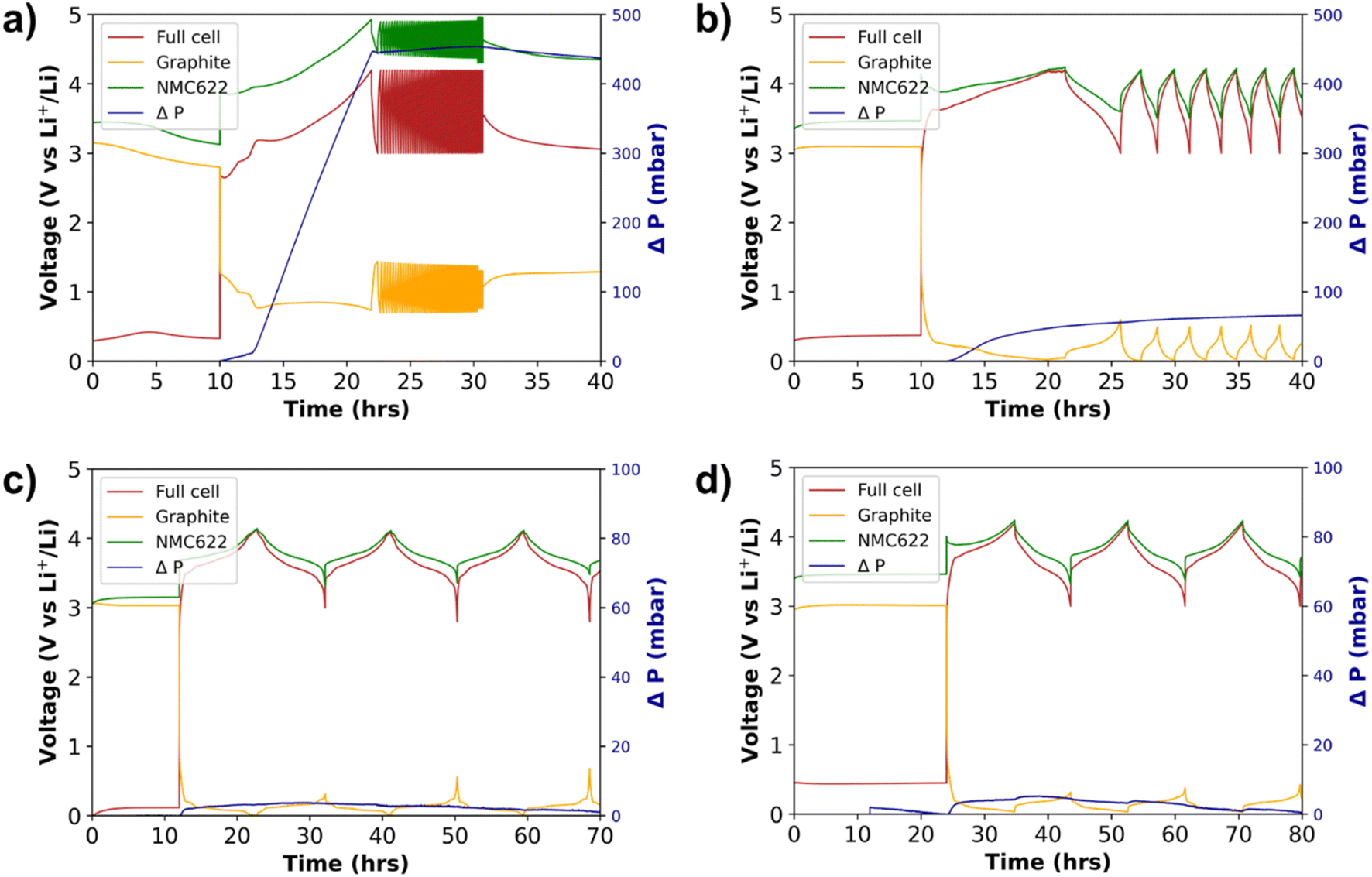 | ||
| Fig. 11 Pressure evolution in 3-electrode cells with NMC622 vs. graphite (Li-metal reference). (a) 1.0 M LiFSI in TEP, (b) 3.0 M LiFSI in TEP, (c) 1.5 M LiFSI in TEP/BTFE and (d) 1.5 M LiFSI in TEP/TTE. | ||
In Fig. 11c and d, the pressure evolution of NMC622|graphite cells during 3 formation cycles at C/10 is shown for the 3-electrode cells cycled with LHCEs of 1.5 M LiFSI in TEP with BTFE or TTE. Compared to the 1.0 M LiFSI TEP where a significant pressure increase was detected, a minimal amount of pressure increase is observed for both LHCEs. Phosphate based electrolytes tend to easily decompose by reduction on the anode, which explains the formation of gaseous products. From the results presented in Fig. 11 it can be seen that this effect is minimized by using the approach of LHCEs, which relies on the concept of high salt concentration and reduced solvent activity on the anode. The stable formation cycles and ICE of about 80% indicate the formation of an appropriate SEI. However, it should be mentioned that the BTFE based electrolyte did not show very good reproducibility with respect to pressure evolution. Fig. S18† shows an example of a cell with the BTFE based electrolyte which causes about 80 mbar pressure increase during the formation cycles. A similar trend was shown during cycling in pouch cells, in which rather unstable and not very reproducible electrochemical data were obtained. In contrast, the TTE based electrolyte showed better reproducibility.
The areal discharge capacity curves in Fig. 12 show that the cell with the TTE based electrolyte has significantly higher areal discharge capacities than the BTFE based electrolyte. Also, the polarization is significantly lower for the TTE based electrolyte, reducing the initial irreversible capacity loss. This is remarkable, since the BTFE based electrolyte has better physicochemical properties (i.e. low viscosity and high conductivity). So, even though the physicochemical properties of the BTFE based electrolyte are better, the better electrochemical performance of the TTE based electrolyte might be attributed to the formation of different solid electrolyte interphases on both the anode and the cathode (more ionically conductive).
 | ||
| Fig. 12 Discharge capacities of 3-electrode cells with NMC622 vs. graphite (Li-metal reference), using (a) BTFE-based electrolyte and (b) TTE-based electrolyte. | ||
3.5 Operando X-ray diffraction
To shed light on the potential solvent co-intercalation into graphite in 1.0 M LiFSI in TEP electrolyte, operando SXRD was performed. The results are presented in Fig. 13, highlighting the main reflections from the graphite electrode. As can be seen, the (002) reflection of pure graphite vanishes quite quickly and a new intense reflection corresponding to lithiated graphite appears at lower scattering angles. The reflection moves to lower 2θ as the cell is cycled, eventually reaching a more or less fixed position once the plateau at around 3.2 V starts, which corresponds to the graphite plateau at 0.8 V from Fig. 11a. As can be seen from Fig. 13, the equivalent d-spacing for the (001) reflection of LiC6 far exceeds that expected from fully lithiated graphite (3.78 vs. 3.70 Å) seen in a recent study by Abe et al.69 It can be concluded that the interlayer spacing between the graphite sheets is larger than for LiC6, which is highly indicative of co-intercalation of TEP. This observation of co-intercalation agrees with the operando pressure measurements where a significant pressure increase was observed at the plateau of 0.8 V. A noteworthy feature is that the transition does not seem to be reversible, which is also indicated by the electrochemical behavior of the cell. | ||
| Fig. 13 Densiometric view of diffraction patterns during operando-SXRD of a NMC622 vs. graphite pouch cell (top) and the corresponding electrochemical behavior (bottom). | ||
4 Conclusion
This study provides insights into the analysis of the solvation structure of localized highly concentrated electrolytes and operando pressure evolution during galvanostatic cycling. Using two complementary techniques of Raman spectroscopy and NMR-spectroscopy to study the solvation structure, we discussed the importance of hidden information due to overlapping peaks of electrolyte components. The results indicated that both BTFE and TTE have a minimal influence on the solvation structure (Li+–TEP) of the TEP-based non-flammable localized highly concentrated liquid electrolyte. However, 13C-NMR has shown that the carbon groups in TEP experience a change in solvation environment, when the diluent concentration is increased. This effect is slightly more profound in the TTE based electrolyte than for BTFE. This experimental finding has also been confirmed by molecular dynamics simulations, which has shown that both FSI and the diluents' fluorine atoms interact with the CH2 and CH3 groups of TEP. However, from 7Li-NMR experiments it has been shown that the Li+ in BTFE based electrolytes experiences more significant deshielding than the TTE based electrolytes. This indicates a more significant change in the solvation sheath when BTFE is added to the highly concentrated electrolyte, compared to when TTE is added. So, different nuclei contributing to the solvation sheath should be carefully analyzed to determine the effect of a diluent on the solvation sheath.Furthermore, molecular dynamics simulations have confirmed the stable Li+–TEP solvation sheath of HCEs in LHCEs. The coulombic interaction of Li+–TEP and FSI–TEP becomes stronger by increasing the salt concentration. This agrees with the observed high viscosity of the HCE. Upon adding the diluents, we observed minor changes in coulombic interactions and interactions between Li+ and TTE or BTFE are negligible. This confirms the minimal influence of the diluents on the solvation structure observed by 13C-NMR. Furthermore, the analysis by RDF on LHCEs showed interactions between both Li+ and FSI's oxygens with TEP, which explain the observed chemical shifts of CH2 groups in TEP. Moreover, it is also shown that the observed chemical shifts of the CH3 groups were caused by the diluent's fluorine atoms. DFT calculations and NCI analysis have confirmed the aforementioned interactions that contribute to the observed NMR chemical shifts.
Even though the differences in the effect of the diluents on the solvation sheath seem to be minor, the electrochemical performance of the electrolytes is significantly different. The cycling performance of the lower-cost TTE based electrolyte was more reproducible and showed enhanced stability during galvanostatic cycling compared to the BTFE based electrolyte. Furthermore, it has been shown that the LHCE with BTFE as the diluent performs better in half-cells, but the LHCE with TTE as the diluent shows higher coulombic efficiencies in full-cells and Li-metal cells. This research thereby highlights that the choice of diluent is important when designing an LHCE for a specific battery application. After all, both diluents do effectively reduce the pressure evolution compared to phosphate-based electrolytes with conventional 1.0 M and high 3.0 M salt concentration. By operando XRD it was also shown that TEP co-intercalates into graphite using 1.0 M LiFSI TEP electrolyte. The results emphasize that the concept of LHCEs can be used to stabilize phosphate-based non-flammable liquid electrolytes. This work also paves the way towards further understanding of the influence of the diluent on the solvation structure and electrochemical performance of LHCEs.
Author contributions
Wessel van Ekeren: planning & execution of all experiments, writing – original draft. Marcelo Albuquerque: classical molecular dynamics and density functional theory simulations, writing – classical MD and DFT. Gustav Ek: analysis of in situ XRD, writing – in situ XRD. Ronnie Mogensen: writing review & editing, supervision. Luciano T. Costa: classical MD and DFT simulations, supervision. Daniel Brandell: writing – review & editing. William Brant: writing – review & editing, supervision. Reza Younesi: writing – review & editing, supervision.Conflicts of interest
The authors have no conflicts to declare.Acknowledgements
The authors would like to acknowledge the financial support by Batteries in Sweden (BASE), funded by Vinnova. Furthermore, the authors would like to acknowledge MAX IV Laboratory for time on DanMAX under Proposal 20211101. Research conducted at MAX IV, a Swedish national user facility, is supported by the Swedish Research council under contract 2018-07152, the Swedish Governmental Agency for Innovation Systems under contract 2018-04969, and Formas under contract 2019-02496. DanMAX is funded by the NUFI grant no. 4059-00009B. Support for Joint Brazilian–Sweden Research Collaboration from CAPES/STINT is also gratefully acknowledged. The computations were enabled by resources provided by the Swedish National Infrastructure for Computing (SNIC) at NSC partially funded by the Swedish Research Council.References
- R. Gond, W. Van Ekeren, R. Mogensen, A. J. Naylor and R. Younesi, Mater. Horiz., 2021, 8, 2913–2928 RSC.
- Y. Noguchi, E. Kobayashi, L. S. Plashnitsa, S. Okada and J. Yamaki, Electrochim. Acta, 2013, 101, 59–65 CrossRef CAS.
- J. W. Hastie, J. Res. Natl. Bur. Stand., Sect. A, 1973, 77, 733–754 CrossRef CAS PubMed.
- K. Xu, M. S. Ding, S. Zhang, J. L. Allen and T. R. Jow, J. Electrochem. Soc., 2003, 150, A161 CrossRef CAS.
- H. Ota, A. Kominato, W. J. Chun, E. Yasukawa and S. Kasuya, J. Power Sources, 2003, 119–121, 393–398 CrossRef CAS.
- R. Mogensen, S. Colbin, A. S. Menon, E. Björklund and R. Younesi, ACS Appl. Energy Mater., 2020, 3, 4974–4982 CrossRef CAS.
- R. Mogensen, A. Buckel, S. Colbin and R. Younesi, Chem. Mater., 2021, 4, 1130–1139 CrossRef.
- Z. Zeng, V. Murugesan, K. S. Han, X. Jiang, Y. Cao, L. Xiao, X. Ai, H. Yang, J. G. Zhang, M. L. Sushko and J. Liu, Nat. Energy, 2018, 3, 674–681 CrossRef CAS.
- J. Wang, Y. Yamada, K. Sodeyama, E. Watanabe, K. Takada, Y. Tateyama and A. Yamada, Nat. Energy, 2018, 3, 22–29 CrossRef CAS.
- Y. Yamada, K. Furukawa, K. Sodeyama, K. Kikuchi, M. Yaegashi, Y. Tateyama and A. Yamada, J. Am. Chem. Soc., 2014, 136, 5039–5046 CrossRef CAS PubMed.
- L. Xiao, Z. Zeng, X. Liu, Y. Fang, X. Jiang, Y. Shao, L. Zhuang, X. Ai, H. Yang, Y. Cao and J. Liu, ACS Energy Lett., 2019, 4, 483–488 CrossRef CAS.
- S. Chen, J. Zheng, L. Yu, X. Ren, M. H. Engelhard, C. Niu, H. Lee, W. Xu, J. Xiao, J. Liu and J. G. Zhang, Joule, 2018, 2, 1548–1558 CrossRef CAS.
- Y. Yamada, J. Wang, S. Ko, E. Watanabe and A. Yamada, Nat. Energy, 2019, 4, 269–280 CrossRef CAS.
- J. N. A. Canongia Lopes and A. A. H. Pádua, J. Phys. Chem. B, 2006, 110, 3330–3335 CrossRef CAS PubMed.
- N. N. Rajput, V. Murugesan, Y. Shin, K. S. Han, K. C. Lau, J. Chen, J. Liu, L. A. Curtiss, K. T. Mueller and K. A. Persson, Chem. Mater., 2017, 29, 3375–3379 CrossRef CAS.
- J. Wang, Y. Yamada, K. Sodeyama, C. H. Chiang, Y. Tateyama and A. Yamada, Nat. Commun., 2016, 7, 1–9 Search PubMed.
- K. Sodeyama, Y. Yamada, K. Aikawa, A. Yamada and Y. Tateyama, J. Phys. Chem. C, 2014, 118, 14091–14097 CrossRef CAS.
- X. Fan, X. Ji, L. Chen, J. Chen, T. Deng, F. Han, J. Yue, N. Piao, R. Wang, X. Zhou, X. Xiao, L. Chen and C. Wang, Nat. Energy, 2019, 4, 882–890 CrossRef CAS.
- X. Fan, L. Chen, O. Borodin, X. Ji, J. Chen, S. Hou, T. Deng, J. Zheng, C. Yang, S. C. Liou, K. Amine, K. Xu and C. Wang, Nat. Nanotechnol., 2018, 13, 715–722 CrossRef CAS PubMed.
- D. M. Halat, R. L. Snyder, S. Sundararaman, Y. Choo, K. W. Gao, Z. J. Hoffman, B. A. Abel, L. S. Grundy, M. D. Galluzzo, M. P. Gordon, H. Celik, J. J. Urban, D. Prendergast, G. W. Coates, N. P. Balsara and J. A. Reimer, Chem. Mater., 2021, 33, 4915–4926 CrossRef CAS.
- A. D. Pauric, I. C. Halalay and G. R. Goward, Phys. Chem. Chem. Phys., 2016, 18, 6657–6667 RSC.
- R. F. W. Bader, Atoms in Molecules: A Quantum Thory, Oxford University Press, 1990 Search PubMed.
- E. R. Johnson, S. Keinan, P. Mori-Sánchez, J. Contreras-García, A. J. Cohen and W. Yang, J. Am. Chem. Soc., 2010, 132, 6498–6506 CrossRef CAS PubMed.
- S. K. Mishra and N. Suryaprakash, RSC Adv., 2015, 5, 86013–86022 RSC.
- C. F. Tormena, Prog. Nucl. Magn. Reson. Spectrosc., 2016, 96, 73–88 CrossRef CAS PubMed.
- T. M. Barbosa, R. V. Viesser, R. J. Abraham, R. Rittner and C. F. Tormena, RSC Adv., 2015, 5, 35412–35420 RSC.
- S. K. Mishra and N. Suryaprakash, Molecules, 2017, 22, 423 CrossRef PubMed.
- G. Hougham, G. Tesoro, A. Viehbeck and J. D. Chapple-Sokol, Macromolecules, 1994, 27, 5964–5971 CrossRef CAS.
- T. Doi, Y. Shimizu, M. Hashinokuchi and M. Inaba, J. Electrochem. Soc., 2017, 164, A6412–A6416 CrossRef CAS.
- S. Chen, J. Zheng, D. Mei, K. S. Han, M. H. Engelhard, W. Zhao, W. Xu, J. Liu and J. G. Zhang, Adv. Mater., 2018, 30, 1706102 CrossRef PubMed.
- L. Yu, S. Chen, H. Lee, L. Zhang, M. H. Engelhard, Q. Li, S. Jiao, J. Liu, W. Xu and J. G. Zhang, ACS Energy Lett., 2018, 3, 2059–2067 CrossRef CAS.
- X. Cao, Y. Xu, L. Zhang, M. H. Engelhard, L. Zhong, X. Ren, H. Jia, B. Liu, C. Niu, B. E. Matthews, H. Wu, B. W. Arey, C. Wang, J. G. Zhang and W. Xu, ACS Energy Lett., 2019, 4, 2529–2534 CrossRef CAS.
- H. Jia, L. Zou, P. Gao, X. Cao, W. Zhao, Y. He, M. H. Engelhard, S. D. Burton, H. Wang, X. Ren, Q. Li, R. Yi, X. Zhang, C. Wang, Z. Xu, X. Li, J. G. Zhang and W. Xu, Adv. Energy Mater., 2019, 9, 1–10 Search PubMed.
- X. Ren, S. Chen, H. Lee, D. Mei, M. H. Engelhard, S. D. Burton, W. Zhao, J. Zheng, Q. Li, M. S. Ding, M. Schroeder, J. Alvarado, K. Xu, Y. S. Meng, J. Liu, J. G. Zhang and W. Xu, Chem, 2018, 4, 1877–1892 CAS.
- X. Ren, L. Zou, X. Cao, M. H. Engelhard, W. Liu, S. D. Burton, H. Lee, C. Niu, B. E. Matthews, Z. Zhu, C. Wang, B. W. Arey, J. Xiao, J. Liu, J. G. Zhang and W. Xu, Joule, 2019, 3, 1662–1676 CrossRef CAS.
- X. Zhang, L. Zou, Y. Xu, X. Cao, M. H. Engelhard, B. E. Matthews, L. Zhong, H. Wu, H. Jia, X. Ren, P. Gao, Z. Chen, Y. Qin, C. Kompella, B. W. Arey, J. Li, D. Wang, C. Wang, J. G. Zhang and W. Xu, Adv. Energy Mater., 2020, 10, 1–11 CAS.
- Q. K. Zhang, X. Q. Zhang, L. P. Hou, S. Y. Sun, Y. X. Zhan, J. L. Liang, F. S. Zhang, X. N. Feng, B. Q. Li and J. Q. Huang, Adv. Energy Mater., 2022, 12, 2200139 CrossRef CAS.
- W. L. Jorgensen, D. S. Maxwell and J. Tirado-Rives, J. Am. Chem. Soc., 1996, 118, 11225–11236 CrossRef CAS.
- Tool to build force field input files for molecular simulation, https://github.com/paduagroup/fftool.
- X. Cao, P. Gao, X. Ren, L. Zou, M. H. Engelhard, B. E. Matthews, J. Hu, C. Niu, D. Liu, B. W. Arey, C. Wang, J. Xiao, J. Liu, W. Xu and J. G. Zhang, Proc. Natl. Acad. Sci. U. S. A., 2021, 118, 1–9 Search PubMed.
- L. Martínez, R. Andrade, E. G. Birgin and J. M. Martínez, J. Comput. Chem., 2012, 32, 174–182 Search PubMed.
- W. F. van Gunsteren and H. J. C. Berendsen, Angew. Chem., Int. Ed. Engl., 1990, 29, 992–1023 CrossRef.
- H. J. C. Berendsen, J. P. M. Postma, W. F. Van Gunsteren, A. Dinola and J. R. Haak, J. Chem. Phys., 1984, 81, 3684–3690 CrossRef CAS.
- M. Parrinello and A. Rahman, J. Appl. Phys., 1981, 52, 7182–7190 CrossRef CAS.
- G. Bussi, D. Donadio and M. Parrinello, J. Chem. Phys., 2007, 126, 014101 CrossRef PubMed.
- B. Hess, H. Bekker, H. J. C. Berendsen and J. G. E. M. Fraaije, J. Comput. Chem., 1997, 18, 1463–1472 CrossRef CAS.
- M. J. Abraham and J. E. Gready, J. Comput. Chem., 2012, 32, 174–182 Search PubMed.
- M. Brehm and B. Kirchner, J. Chem. Inf. Model., 2011, 51, 2007–2023 CrossRef CAS PubMed.
- M. Brehm, M. Thomas, S. Gehrke and B. Kirchner, J. Chem. Phys., 2020, 152, 164105 CrossRef CAS PubMed.
- W. Humphrey, A. Dalke and K. Schulten, J. Mol. Graphics, 1996, 14, 33–38 CrossRef CAS PubMed.
- J. Da Chai and M. Head-Gordon, J. Chem. Phys., 2008, 128, 084106 CrossRef PubMed.
- Y. S. Lin, G. De Li, S. P. Mao and J. Da Chai, J. Chem. Theory Comput., 2013, 9, 263–272 CrossRef CAS PubMed.
- A. Najibi and L. Goerigk, J. Chem. Theory Comput., 2018, 14, 5725–5738 CrossRef CAS PubMed.
- M. Bursch, J. Mewes, A. Hansen and S. Grimme, Angew. Chem., 2022, 134, e202205735 CrossRef.
- T. Lu and F. Chen, J. Comput. Chem., 2012, 33, 580–592 CrossRef CAS PubMed.
- F. Neese, Wiley Interdiscip. Rev.: Comput. Mol. Sci., 2012, 2, 73–78 CAS.
- F. Neese, F. Wennmohs, U. Becker and C. Riplinger, J. Chem. Phys., 2020, 152, 224108 CrossRef CAS PubMed.
- B. D. Adams, J. Zheng, X. Ren, W. Xu and J. G. Zhang, Adv. Energy Mater., 2018, 8, 1702097 CrossRef.
- M. S. Ding, K. Xu, S. S. Zhang, K. Amine, G. L. Henriksen and T. R. Jow, J. Electrochem. Soc., 2001, 148, A1196 CrossRef CAS.
- D. W. McOwen, D. M. Seo, O. Borodin, J. Vatamanu, P. D. Boyle and W. A. Henderson, Energy Environ. Sci., 2014, 7, 416–426 RSC.
- S. Li, S. Zhang, S. Chai, X. Zang, C. Cheng, F. Ma, L. Zhang and Y. Lu, Energy Storage Mater., 2021, 42, 628–635 CrossRef.
- Y. Yamada, M. Yaegashi, T. Abe and A. Yamada, Chem. Commun., 2013, 49, 11194–11196 RSC.
- K. Xu, M. S. Ding, S. Zhang, J. L. Allen and T. R. Jow, J. Electrochem. Soc., 2002, 149, A622 CrossRef CAS.
- L. Yang, A. Xiao and B. L. Lucht, J. Mol. Liq., 2010, 154, 131–133 CrossRef CAS.
- R. Sadeghi and F. Jahani, J. Phys. Chem. B, 2012, 116(17), 5234–5241 CrossRef CAS PubMed.
- A. Krid, L. Belkhiri, H. Allal, A. Kuznetsov and A. Boucekkine, Struct. Chem., 2022, 1–14 Search PubMed.
- A. Lakshmipriya and N. Suryaprakash, J. Phys. Chem. A, 2016, 120, 7810–7816 CrossRef CAS PubMed.
- S. Schweidler, L. De Biasi, A. Schiele, P. Hartmann, T. Brezesinski and J. Janek, J. Phys. Chem. C, 2018, 122, 8829–8835 CrossRef CAS.
- H. Fujimoto, T. Yamaki, K. Shimoda, S. Fujinami, T. Nakatani, G. Kano, M. Kawasaki, Z. Ogumi and T. Abe, J. Electrochem. Soc., 2022, 169, 070507 CrossRef.
Footnote |
| † Electronic supplementary information (ESI) available. See DOI: https://doi.org/10.1039/d2ta08404j |
| This journal is © The Royal Society of Chemistry 2023 |