
Boosted charge separation in direct Z-scheme heterojunctions of CsPbBr3/Ultrathin carbon nitride for improved photocatalytic CO2 reduction†
Fanqi
Luo
a,
Mingyang
Liu
b,
Mang
Zheng
b,
Qi
Li
*b,
Hong
Wang
*a,
Jing
Zhou
c,
Yong
Jiang
d,
Yaoguang
Yu
e and
Baojiang
Jiang
 *a
*a
aKey Laboratory of Functional Inorganic Material Chemistry, Ministry of Education of the People’s Republic of China, School of Chemistry and Materials Science, Heilongjiang University, Harbin 150080, China. E-mail: wanghong1@hlju.edu.cn; jbj@hlju.edu.cn
bCollege of Material Science and Chemical Engineering, Harbin Engineering University, Harbin 150001, China. E-mail: liqchem@sina.com
cShanghai Institute of Applied Physics, Chinese Academy of Sciences, Shanghai 201800, China
dCollege of Biological and Chemical Engineering, Guangxi University of Science and Technology, Liuzhou 545006, China
eSchool of Materials, Sun Yat-sen University, Shenzhen 518107, P. R. China
First published on 21st November 2022
Abstract
Realizing CO2 reduction with H2O oxidation on g-C3N4-based photocatalysts is quite promising yet challenging. Herein, an efficient direct Z-scheme heterostructure of ultrathin CsPbBr3/g-C3N4 nanosheets is fabricated via a simple electrostatic self-assembly process, resulting in an effective photocatalytic reduction of CO2 to CH4 (184.0 μmol g−1) and CO (105.2 μmol g−1) with oxidation of H2O under AM 1.5G irradiation. Notably, in situ X-ray photoelectron spectroscopy (XPS) analysis demonstrated that a direct Z-scheme charge transfer mechanism at the CsPbBr3 and g-C3N4 interface is enabled, thereby achieving efficient charge separation and high redox potentials to drive photocatalytic CO2 reduction and H2O oxidation synchronously. Isotopic labelling experiments revealed that the adsorbed water is activated to release H atoms and eventually assists the CO2 reduction. Theoretical calculations further revealed that the p orbitals of Pb atoms hybridize with the 2π* orbitals of CO2 molecules, strengthening the affinity of CO2 and weakening the binding strength. Moreover, overlapping between Pb p orbitals and 5σ orbitals of CO molecules promote the protonation of CO* intermediates. This work provides an in-depth understanding and guidance for constructing high-efficiency catalysts for CO2 reduction with H2O oxidation.
1. Introduction
Excessive consumption of fossil fuels and continuous emission of carbon dioxide (CO2) have caused serious environmental problems.1–5 Inspired by plant photosynthesis, artificial photosynthesis provides promising strategies for achieving simultaneous CO2 reduction and H2O oxidation into high-valued hydrocarbon fuels under mild conduction, alleviating energy crisis and environmental issues such as severe global warming and associated climate change issues.6–9 However, this remains a huge challenge owing to the high chemical inertness of CO2 molecules, slow kinetics of H2O oxidation and multi-electron transfer pathways with high reaction barriers.10–13 Therefore, it is increasingly urgent for exploring higher efficiency catalysts for the photo-reduction of CO2 and H2O oxidation.Graphitic carbon nitride (g-C3N4) as a two-dimensional organic semiconductor exhibited excellent chemical stability and photoelectric catalytic performance, which has been investigated for photocatalytic CO2 reduction.14–19 However, bulk g-C3N4 exhibits unsatisfactory efficiency owing to the fast recombination and poor migration of photogenerated carriers. In this regard, many efforts have been explored to improve the activity of g-C3N4-based photocatalysts, such as heteroatom doping, defect modifying and nanostructure designing.20,21 Among these, exfoliating bulk g-C3N4 into ultrathin nanosheets has attracted much attention benefiting from unique two-dimensional structural features, such as large specific surface area, promoting electron excitation and short charge diffusion distance, and the resultant ultrathin g-C3N4 demonstrated a significant increase in photocatalytic activity.22–26 However, developing a single-component layered g-C3N4 photocatalysts for CO2 reduction coupled with H2O oxidation has proven difficult because of the thermodynamic conflict between optical absorption and redox potentials. Recently, constructing layered g-C3N4-based 2D/2D heterostructures has been regarded as a quite promising strategy for enabling spatial separation of carriers with high redox potentials. Ye et al. fabricated 2D/2D van der Waals heterojunctions via assembling UiO-66 into g-C3N4 nanosheets, which showed intimate electronic coupling at the interface and improved photocatalytic CO2 conversion efficiency.27 Li et al. prepared 2D/2D Co2P@BP/g-C3N4 heterojunctions via a simple self-assembly method, which exhibited dramatically enhanced photocatalytic activity and selectivity for CO2 conversion.28
Besides, the properly aligned band structures and effective active sites are crucial for exploring high-efficiency g-C3N4 composite catalysts in photocatalytic CO2 reduction.12,13,29 Lead halide perovskites (LHPs) have emerged as promising materials, owing to easy facile processing and excellent optoelectronic properties.30–33 In addition, its sufficiently negative conduction band edge highlights the excellent CO2 reduction ability.34–36 In particular, CsPbBr3 is a typical halide perovskite material, which has gained significant interest in solar CO2 conversion, due to strong light harvesting ability, high carrier mobility and long carrier diffusion length.37–39 Considering the distinctive photocatalytic properties of CsPbBr3, the increased photocatalytic CO2 reduction performance can be realized by integrating it with other semiconductors.40–42 Kuang et al. fabricated a α-Fe2O3 nanorod/CsPbBr3 Z-scheme heterojunction using amine functional graphene oxide interlayers, which can integrate the strong reduction ability of CsPbBr3 and the strong oxidation ability of α-Fe2O3 to efficiently convert CO2 and H2O into CH4 and O2.43 Yu et al. designed a TiO2/CsPbBr3 heterojunction via a simple electrostatic assembly, where electron-rich CsPbBr3 nanocrystals can serve as active sites by donating electrons to activated CO2 molecules for producing H2 and CO.44 Inspired by these advantages, the 2D/2D Z-type heterostructure established by CsPbBr3 and ultrathin g-C3N4 will enhance the carrier separation and transfer efficiency as well as the CO2 adsorption and activation capacity, thereby enhancing the photocatalytic CO2 reduction performance.
In this work, we assembled the pre-fabricated ultrathin CsPbBr3 nanosheets (CPBNs) and g-C3N4 nanosheets (CNNs) to form a 2D/2D facet-contact Z-scheme heterostructure via strong electrostatic interactions. In addition, close face-contact CsPbBr3/C3N4 realized a heterojunction with a large-area heterointerface by finely controlling the surface charge, thereby ensuring efficient Z-scheme charge transfer and promoting charge separation. In particular, in situ X-ray photoelectron spectroscopy (XPS) and band structure analysis showed that a direct Z-scheme charge transfer pathway was established between CsPbBr3 and g-C3N4, thus effectively promoting carrier separation and generating high redox potentials. Moreover, density functional theory (DFT) calculations demonstrated that the presence of an internal electric field at CPBN/CNN interfaces increases the efficiency of photoinduced charge carrier separation. It is exciting that by optimizing the amount of CPBNs, the resulting Z-scheme CPBN/CNN photocatalysts deliver more excellent photocatalytic activity in CO2 reduction with H2O oxidation (184.0 μmol g−1 for CH4, 105.2 μmol g−1 for CO, and 398.3 μmol g−1 for O2) compared with CNNs. This study provides a new direction for the construction of g-C3N4-based photocatalysts using a halide perovskite as a semiconductor in the field of photocatalytic overall reaction for CO2 and H2O conversion.
2. Experimental section
2.1 Materials and reagents
Lead acetate (Pb(AC)2), caesium bromide (CsBr), oleylamine (OA), oleic acid (OLA), melamine and phosphorous acid were purchased from Aladdin Reagents. Ethanol (C2H5OH, 99.8%), ethylene glycol (C2H6O2, 99.8%) and isopropyl alcohol (C3H8O, 99%) were bought from Tianjin Fuyu Fine Chemical Industry Co. Ltd. All chemical reagents were commercially available and purchased from reagent companies.2.2 Materials synthesis
2.3 Characterization
The zeta potential of the sample were measured using a Zeta sizer Nano ZS90 (Malvern S4 Instruments) in isopropyl alcohol. The morphology and microstructure of the samples were investigated using a Zeiss Sigma-500 field emission scanning electron microscope (SEM) operating at an accelerating voltage of 5 kV, and a JEOL JEM-F200 transmission electron microscope (TEM) operating at an accelerating voltage of 200 kV. The crystal structures were obtained by X-ray powder diffraction (XRD, Rigaku D/max-IIIB, Cu Kα, λ = 1.5406 Å radiation). X-ray photoelectron spectroscopy (XPS) analysis was performed using a VG ESCALAB MK II equipped with a Mg Kα (1253.6 eV) achromatic X-ray source. The UV-vis diffuse reflectance spectra (UV-Vis DRS) of the samples were recorded using a Shimadzu UV-2550 UV-visible spectrophotometer with BaSO4 as the reference. The steady-state photoluminescence (PL) was recorded using an Edinburgh FSL1000 fluorescence spectrophotometer at room temperature. The time-resolved photoluminescence (TRPL) spectra were recorded using an Edinburgh instruments F980.2.4 Photocatalytic CO2 reduction
2.5 Photoelectrochemical characterization
All electrochemical and photoelectrochemical measurements were performed on an electrochemical workstation using a three-electrode system (Princeton Versa STAT). Typically, a piece of FTO glass with a prepared photocatalyst coating served as the working electrode, a platinum foil as the counter electrode, and a saturated Ag/AgCl electrode as the reference electrode. The 0.05 M tetrabutylammonium hexafluorophosphate (TBAPF6)/dichloromethane solution was filled in the quartz cell as the electrolyte. The photocurrents were recorded using a Chi electrochemical workstation under irradiation of a 150 W Xe lamp at a potential of −0.4 V.2.6 DFT sections
All theoretical calculations were performed using the Vienna Ab initio Simulation Package. Projected augment wave (PAW) with generalised gradient approximation (GGA) and Perdew–Burke–Ernzerhof (PBE) functional described the interactions between ions and electrons. The energy cutoff was set at 400 eV, and the K point mesh was set as 2 × 2 × 1. In this work, a g-C3N4 model for melon type and a CsPbBr3 slab with the (110) surface was constructed. All atoms were fully relaxed until the total energy difference reached below 1 × 10⁻⁶ eV per atom and force was less than 0.05 eV Å−1.3. Results and discussion
3.1 Structural characterization
Fig. 1a illustrates the fabrication route of 2D/2D CPBN/CNN hybrids. First, the CPBN was prepared via reacting Pb(AC)2 with CsBr in isopropyl using oleic acid and oleylamine, and the ultrathin CNN was prepared via a thermal-induce exfoliation strategy. From the transmission electron microscopic (TEM) and atomic force microscopic (AFM) observation, the obtained CPBNs have a lateral size of approximately 300 nm with a vertical thickness of about 3 nm, and CNNs represent the laminar structure with a thickness of approximately 2 nm (Fig. S1†). Undoubtedly, these ultrathin nanosheets present high surface areas, abundant photocatalytic active sites and greatly short transport distance of photogenerated charge carriers.45 | ||
| Fig. 1 (a) Schematic diagram of the 2D/2D CPBN/CNN heterojunction prepared via an electrostatic self-assembly process. (b) Zeta potentials of CPBNs and CNNs in isopropanol. (c) XRD patterns of the CNN, CPBN and CPBN/CNN. (d) TEM image of CPBN/CNN and (e) HRTEM image of the selected area in (d). (f) Element mapping images of single elements. | ||
Furthermore, it is advantageous for assembling these ultrathin nanosheets via a mutual Coulomb electrostatic interaction. The zeta potentials of the as-prepared CNNs and CPBNs in the isopropanol solvent are shown in Fig. 1b. It is observed that the surface of CPBNs is negative with a zeta potential of −6.42 mV, while that of CNNs is positive with a zeta potential of +4.06 mV. The opposite surface charges would cause strong electrostatic attraction between the negatively charged CPBNs and positively charged CNNs for constructing the CPBN/CNN 2D/2D heterostructure with close interface contacts.46,47 X-ray diffraction (XRD) patterns of CPBN/CNN (Fig. 1c) obviously exhibit typical peaks of both CsPbBr3 and g-C3N4. The diffraction peak at 27.3° matches well with the (002) plane of g-C3N4. Meanwhile, the diffraction patterns located at 15.0°, 21.3°, 30.4°, 34.1°, 37.4° and 43.5° corresponded to the (100), (110), (200), (210), (211) and (220) planes of cubic phase CsPbBr3 (JCPDS No. 73-2020), which increased with the CPBN content (Fig. S2†). By comparing with the Raman spectrum of CNNs, there are many new characteristic peaks, indicating that the intimate contact and electrostatic interaction formed between CPBNs and CNNs (Fig. S3†). The TEM image of the CPBN/CNN heterojunction (Fig. 1d) clearly demonstrates a tightly packed structure with small sheets closely arranged on the big sheets. The high-resolution TEM (HRTEM) image affirmed that these small nanosheets are CsPbBr3 with a lattice spacing of 0.419 Å, corresponding to the (110) facet (Fig. 1e). The energy-dispersive X-ray spectroscopy (EDX) and corresponding elemental mappings analysis further identified that all the characteristic elements including Cs, Pb, Br, C and N can be clearly observed in the hybrid (Fig. 1f and S4†). C and N elements are uniformly distributed in the whole sheets, and Cs, Pb and Br elements are concentrated in small range, indicating that CsPbBr3 nanosheets are dispersedly stacked on the surface of g-C3N4, which matches well with the TEM image.
Furthermore, the surface chemical state and heterointerface interaction of CPBN/CNN was investigated by X-ray photoelectron spectroscopy (XPS). The XPS full survey spectrum identifies the presence of C, N, Cs, Pb and Br in CPBN/CNN hybrids (Fig. S5†). As observed in Fig. 2a, the C 1s spectrum of CPBN/CNN is resolved into three characteristic peaks centered at 284.60, 285.99 and 287.94 eV, which are assigned to C–C, C–NH2 and N–C![[double bond, length as m-dash]](https://www.rsc.org/images/entities/char_e001.gif) N, respectively.48 Compared with pristine CNNs, these characteristic peaks negatively shift by 0.13 eV, and the same shift can be observed in the N 1s spectrum. The binding energies of N 1s appear at 398.35, 399.36 and 400.85 eV, which are assigned to the N atoms in C–NC, N–(C)3 and C–NH2, while these peaks are of high value in CNNs (Fig. 2b). In contrast, the binding energies of the Cs 3d and Pb 4f spectra show the opposite trend. The binding energies of Cs 3d5/2 and Cs 3d3/2 appear at 724.20 and 738.15 eV, which are higher than those of CPBNs (Fig. 2c), while the Pb 4f7/2 (138.10 eV) and Pb 4f5/2 (142.96 eV) peaks are 0.20 eV higher than those of CPBNs (Fig. 2d). The results of XPS spectra verified the electron migration from CPBNs to CNNs upon hybridization, indicating the intimate contact and strong chemical interaction at interfaces.
N, respectively.48 Compared with pristine CNNs, these characteristic peaks negatively shift by 0.13 eV, and the same shift can be observed in the N 1s spectrum. The binding energies of N 1s appear at 398.35, 399.36 and 400.85 eV, which are assigned to the N atoms in C–NC, N–(C)3 and C–NH2, while these peaks are of high value in CNNs (Fig. 2b). In contrast, the binding energies of the Cs 3d and Pb 4f spectra show the opposite trend. The binding energies of Cs 3d5/2 and Cs 3d3/2 appear at 724.20 and 738.15 eV, which are higher than those of CPBNs (Fig. 2c), while the Pb 4f7/2 (138.10 eV) and Pb 4f5/2 (142.96 eV) peaks are 0.20 eV higher than those of CPBNs (Fig. 2d). The results of XPS spectra verified the electron migration from CPBNs to CNNs upon hybridization, indicating the intimate contact and strong chemical interaction at interfaces.
 | ||
| Fig. 2 XPS of the CNN, CPBN and CPBN/CNN-3: C 1s (a), N 1s (b), Cs 3d (c), and Pb 4f (d). | ||
3.2 Influencing factors of photocatalytic activity
The band structures of CPBNs and CNNs were determined by ultraviolet visible diffusion reflectance spectroscopy (DRS) and ultraviolet photoelectron spectroscopy (UPS). As shown in Fig. 3a, the absorption edge of CNNs and CPBNs are located at 473 and 546 nm, corresponding to the intrinsic bandgaps of 2.62 and 2.27 eV, respectively. The adsorption edge of CPBN/CNN hybrids is composed of CPBNs and CNNs except a little shift, resulting from the strong interfacial interaction between CPBNs and CNNs. The position of VB edge (EVB) in CNNs and CPBNs were further measured via UPS. As shown in Fig. 3b and c, the upper onset and secondary onset energies in the UPS spectra for CNNs were estimated to be 16.05 and 1.25 eV, and those for CPBNs are 16.99 and 1.74 eV. Thus, the EVB values of CNNs and CPBNs were estimated to be 1.96 and 1.53 V (vs. normal hydrogen electrode (NHE) potential).49,50 Combined with the optical bandgap, the CB edge (ECB) of CNNs and CPBNs were estimated to be −0.66 and −0.74 V (vs. NHE), respectively. Meanwhile, the work functions of CPBNs and CNNs were estimated to be 4.23 and 5.15 eV (vs. vacuum), indicating that the Fermi level of CPBNs is higher than that of CNNs, which observe the same results in Kelvin probe spectrum (Fig. S6†). | ||
| Fig. 3 (a) UV-vis DRS spectra of photocatalysts and the calculated band gaps of CNNs and CPBNs. (b and c) UPS valence spectrum of CNNs and CPBNs. In situ irradiation XPS spectra of N 1s (d), Cs 3d (e) and Pb 4f (f). (g) Energy band diagram before and after contact, showing the formation of energy band bending and BIEF, which facilitate the Z-scheme charge transfer and photocatalytic reaction. (h) Time-resolved transient PL spectrum. | ||
When CPBNs contact CNNs, electrons will transfer from CPBNs to CNNs to equilibrate the Fermi level and generate an IEF at interfaces. Furthermore, the charge transfer between CPBNs and CNNs was explored by in situ irradiated XPS. For CPBN/CNN in the darkness, the N 1s peaks shift positively by 0.24 eV, while the Cs 3d and Pb 4f peaks shift negatively by 0.23 and 0.22 eV under light irradiation (Fig. 3d–f).
The binding energy shift demonstrated that photogenerated electrons in CNNs migrate to CPBNs under light irradiation. The above-mentioned analysis demonstrate a direct Z-scheme charge transfer mechanism between CPBNs and CNNs (Fig. 3g).51,52 The CPBNs have a positive Fermi level and band position than CNNs, which induce the electrons in CPBNs to transfer to CNNs until their Fermi level attains equilibrium, causing the band bending and an IEF with the direction of CPBNs to CNNs at the interface. Upon irradiation, the VB electrons in CPBNs and CNNs are excited to the CB. The IEF and band bend drive the photogenerated electrons in the CNN CB to recombine with holes in the CPBN VB. Afterward, the electron-rich CPBNs can serve as reductive sites, donating electrons to active CO2 to producing CO and CH4, and the hole-rich CNNs act as active sites to oxidize H2O molecules to producing O2.
The efficient charge separation between CPBNs and CNNs were further investigated by photoluminescence (PL) and time-resolved PL (TRPL) measurements. The PL spectrum of CNNs represents the strongest emission peak center at 450 nm, which is attributed to radiative recombination within heptazine units (Fig. S7†). As compared with CNNs, CPBN/CNN exhibits a weak emission peak, implying that the presence of CPBNs efficiently inhibits the electron–hole recombination in CNNs, and the blue-shift can be associated with the strong interfacial coupling.53,54 Furthermore, the TRPL decay spectroscopy is analysed for exploring the lifetime of carriers transfer dynamics. The average fluorescence lifetimes of CNNs and CPBNs were calculated to be 14.63 ns and 12.57 ns, by fitting the decay plot with three-exponential equations (Fig. 3h and Table S1†). After CPBNs contact CNNs, the average lifetime of CPBN/CNN significantly prolongs to 23.72 ns, suggesting that the interfacial charge transfer is efficiently improved.55 Photoelectric-chemical tests were performed to investigate the charge carrier separation efficiency. The CPBN/CNN-3 exhibits significantly higher anodic photocurrent in comparison with CPBNs and CNNs, indicating that the transport and separation efficiency are largely improved in the CPBN/CNN-3 heterojunction (Fig. S8†). The diameter of the Nyquist plots reflects the charge-transfer resistance at the electrode/electrolyte interface. The CPBN/CNN-3 electrode possesses a smaller radius in comparison to CPBN and CNN electrodes, demonstrating the lowest resistance for charge carrier transfer (Fig. S9†). The above-mentioned experimental results fully certify that the advantages of combination of CPBNs and CNNs in promoting charge transfer and separation, which is beneficial for photocatalytic CO2 reduction.
3.3 Photocatalytic performance
Subsequently, the photocatalytic CO2 conversion performance of CPBN/CNN-x, CPBNs and CNNs was investigated. The catalytic reaction was carried out in a CO2–saturated mixture solution of ethyl acetate and water under AM 1.5G irradiation. As shown in Fig. 4a–c, all samples show that the products consist of CH4, CO and O2, which increase linearly with the prolonged reaction time. CPBNs and CNNs exhibit lower production of CH4 (17.6 and 15.3 μmol g−1), CO (16.8 and 12.9 μmol g−1) and O2 (35.4 and 30.6 μmol g−1). Notably, the photocatalytic activity is significantly enhanced with the increase in the loading amount of CPBNs, and CPBN/CNN-3 (the mass ratio of CPBNs to CNNs is 3/10) reaches the best CO2 reduction performance with yields of 184.0 μmol g−1 and 105.2 μmol g−1 for CH4 and CO respectively after 4 h of continuous illumination. O2 is also produced in the reaction system with a yield of 398.3 μmol g−1, which could be attributed to H2O oxidation as the number of photoelectrons participating in the reduction reaction is nearly equal to that in the oxidation reaction (Fig. S10†). The electron consumption rate (Relectron) of CPBN/CNN-3 was calculated to be 420.6 μmol g−1 and the corresponding electron consumption yield (Yieldelectron) was calculated to be 1682.4 μmol g−1, which is 11.3-fold of CNNs and 9.6-fold of CPBNs and obviously better than most known catalysts. Further increasing the CPBN amount is detrimental to the photocatalytic activity because overloading CPBNs will decrease the effective interface area and shield light adsorption. The CPBN/CNN provides CO2 reduction activities under different H2O contents, in which the appropriate H2O content is favorable for CO2 reduction (Fig. S11†). The cycling test indicates that no morphological changes and decomposition of CPBNs are observed in the TEM image and XRD spectrum, and the photocatalytic activity remains at the origin performance (Fig. 4d and S12†). As illustrated in Fig. 4e and f, it is observed that the yield of reduction products of CH4 and CO almost increased linearly over 20 h, which achieves a high yield of 917.2 μmol g−1 for CH4, 524.8 μmol g−1 for CO and 2032.6 μmol g−1 for O2 with electron consumption of 8387.2 μmol g−1, implying the excellent stability of CPBN/CNN-3 during the photocatalytic CO2 reduction process. The amount of oxygen evolution is always close to one-fourth of electron consumption for CO2 reduction. Furthermore, the apparent quantum efficiency (AQE) of the prepared CPBN/CNN was calculated to be 0.26% at 420 nm (Fig. S13 and Table S5†).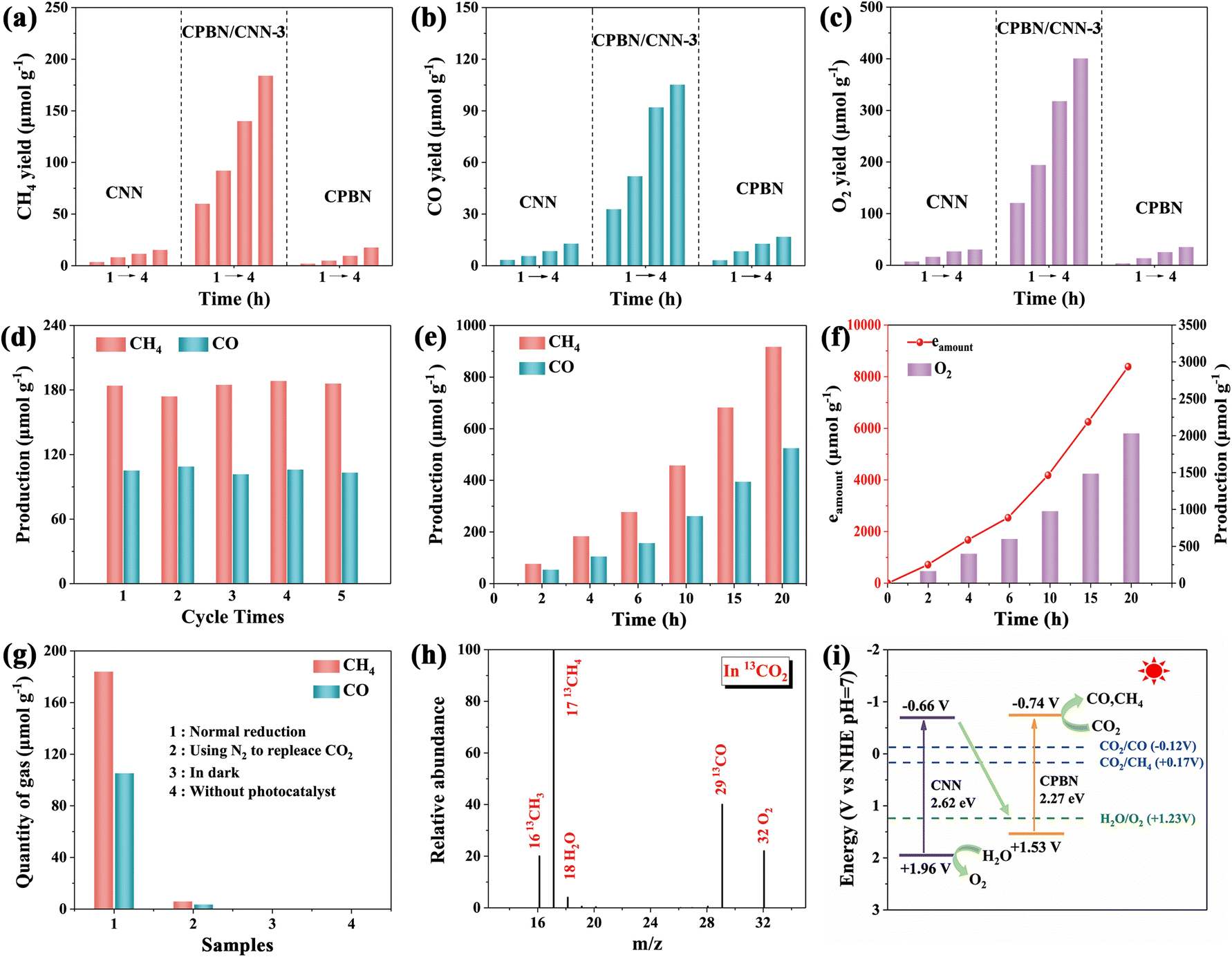 | ||
| Fig. 4 . CO2 photoreduction performance. (a) CH4, (b) CO and (c) O2 yields of the CNN, CPBN and CPBN/CNN-3 by recording every 1 h upon illumination for 4 h. (d and e) Long-term photocatalytic tests of CPBN/CNN-3. (f) Amounts of electron consumption (eamount) for the generation of CH4 and CO (left vertical axis) and the yield of O2 (right vertical axis) of CPBN/CNN-3. (g) Evolution of CH4 and CO under different reaction conditions. (h) GC-MS spectrum of the gas-phase products driven for CPBN/CNN-3 in the photocatalytic reduction of 13CO2. (i) Schematic diagram of the interfacial electron transfer of electrons and holes on g-C3N4 and CsPbBr3 nanosheets. | ||
In order to confirm the C and O source in the photocatalytic reaction, control photocatalytic experiments were carried out (Fig. 4g). CH4 and CO are not detected in the absence of light or catalysts, indicating that products only originated from photocatalytic process. By replacing CO2 with N2, only a small amount of product was detected, which should originate from the partial oxidation of ethyl acetate or organic ligands in CPBNs. The 13CO2 isotope trace experim-ent observed 13CH4 (m/z = 17), 13CO (m/z = 29) and 16O2 (m/z = 32) in the gas chromatography mass spectrometer spectrum (Fig. 4h). When H2O is replaced with H218O, 18O2 (m/z = 36) and 16O2 (m/z = 32) are observed, which originate from H218O or H216O (Fig. S14†). Additional experiments by replacing H2O with D2O shows that H2O is the proton source for CH4 as CD4 is not detected, which is attributed to the heavier atomic mass of D2O that weakened its reactivity (Fig. S15†). These results indicated that the CH4 and CO production is derived from CO2 reduction along with H2O oxidation into O2, in which the photogenerated electrons in the CPBNs participate in the reduction of CO2 molecules with the assistance of protons, while H2O is oxidized to O2 and protons by the holes in CNNs (Fig. 4i).
To deeply investigate the charge transfer mechanism and internal electric field, theoretical calculations based on density functional theory were performed. The work function of g-C3N4 (001) slab and CsPbBr3 (110) slab was estimated from the electrostatic potential of the material surface, which is an important parameter to investigate the electron transfer of heterojunctions. As shown in Fig. 5a and b, the work function of CsPbBr3 (110) slab was calculated as 2.91 eV similar to that of g-C3N4 (001) slab (5.68 eV). Therefore, when the CsPbBr3 (110) slab contacts the g-C3N4 (001) slab, the free electrons in CsPbBr3 with a high Fermi level will spontaneously transfer to g-C3N4 with a low Fermi level via the interface until achieving equilibrium. The charge difference based on the CsPbBr3/g-C3N4 heterojunctions verifies that the diffusion of electrons induces the charge redistribution at the interface, in which the interface near the CsPbBr3 side generates an electron depletion layer with a positive charge and the electron accumulation layer with a negative charge appears near the g-C3N4 side. As a result, the charge redistribution at the interface contributes to the IEF point from CsPbBr3 to g-C3N4, providing a strong drive force for promoting the separation and migration of photogenerated charges, which is consistent with XPS and UPS results (Fig. 5c). Subsequently, the electronic location function was employed to investigate the interaction between CO2 and the surface of photocatalysts. As depicted in Fig. 5d, the Pb and Br atoms in the CsPbBr3 (110) surface exhibit a strong electrostatic attraction toward C and O atoms in CO2, resulting in more variation in OCO bending than that in the g-C3N4 (100) surface, and further indicating that adsorbed CO2 is activated more easily in the CsPbBr3 (110) surface. The project density of states (PDOS) and crystal orbital Hamilton population (COHP) were calculated to evaluate the CO2 internal band interaction in the difference surface model. After interaction with CO2, CsPbBr3 and g-C3N4 show the fast adsorption of CO2, as the 1π and 7σ orbitals of CO2 shift downwards the Fermi level. Notably, for the CsPbBr3 (110) slab, the Pb p orbitals overlap the 2π* orbitals, indicating the favorable activation of CO2 molecules.56 Besides, a lower 2π* energy level of CO2 in the CsPbBr3 (110) surface demonstrates stronger CO2 adsorption and activation in the COHP spectrum (Fig. 5f). For CO adsorption, the 1π and 5σ orbitals of CsPbBr3 shift downwards the Fermi level as compared to g-C3N4. Meanwhile, the Pb p orbitals overlap the 5σ and 2π* orbitals, which is favorable for the interaction with CO* intermediates.57 Combined with the COHP changes of the C–O bond, it can be verified that the CsPbBr3 (110) surface is favorable for protonation of CO* intermediates to CH4.
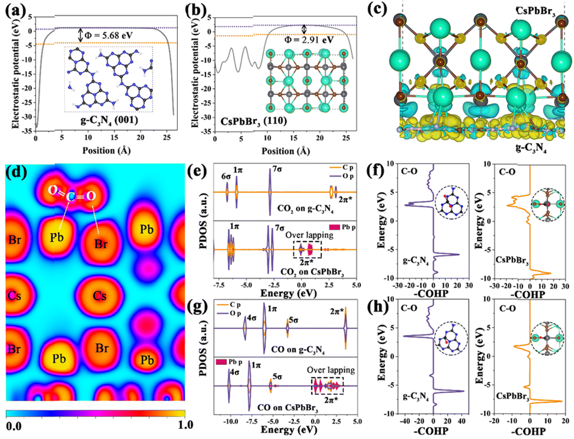 | ||
| Fig. 5 Electrostatic potentials of (a) g-C3N4 and (b) CsPbBr3. (c) Charge difference between distribution for the CsPbBr3/C3N4 heterojunction interface; the blue and yellow iso-surfaces stand for electron depletion and accumulation respectively. (d) Electron local function of CO2 adsorption on CsPbBr3/g-C3N4, DOS and COHP analysis in terms of adsorption for g-C3N4 and CsPbBr3 with CO2 (e and f) and CO (g and h) interaction. | ||
4. Conclusions
In summary, a direct Z-scheme 2D/2D heterojunction has been fabricated via assembling CsPbBr3 nanosheets (CPBNs) onto ultrathin g-C3N4 nanosheets (CNNs), realizing the enhanced photocatalytic performance toward synchronous CO2 reduction and H2O oxidation. Benefiting from appropriate band alignment and close interfacial contact, an effective Z-scheme charge transfer pathway was established between CPBNs and CNNs, promoting charge separation and ensuring high redox ability, which was confirmed by in situ XPS, UPS and TRPL characterizations. The theoretical calculations further verified that the p–p hybridization between Pb atoms and CO2 and CO intermediates enables the efficient activation of CO2 and weakens the binding strength of C–O bonds. Therefore, the CPBN/CNN heterojunctions exhibit a remarkable photocatalytic performance for reducing CO2 to CH4 (184.0 μmol g−1) and CO (105.2 μmol g−1) with H2O oxidation. We believe that this 2D/2D heterostructure may provide a new perspective for improving the photocatalytic performance of C3N4 and supply an important guidance for the design of photocatalytic overall reaction systems.Conflicts of interest
There are no conflicts to declare.Acknowledgements
This work was supported by the National Natural Science Foundation of China (52273264), Outstanding Youth Fund of Heilongjiang Province (JQ 2020B002). Guangxi Science and Technology Base and Talent Special Project NO. AD21075001.Notes and references
- X. X. Chang, T. Wang and J. L. Gong, Energy Environ. Sci., 2016, 9, 2177–2196 RSC.
- L. Ran, Z. W. Li, B. Ran, J. Q. Cao, Y. Zhao, T. Shao, Y. R. Song, M. K. H. Leung, L. C. Sun and J. G. Hou, J. Am. Chem. Soc., 2022, 144, 17097–17109 CrossRef CAS PubMed.
- J. J. Wang, S. Lin, N. Tian, T. Y. Ma, Y. H. Zhang and H. W. Huang, Adv. Funct. Mater., 2021, 31, 2008008 CrossRef CAS.
- J. W. Wang, L. Z. Qiao, H. D. Nie, H. H. Huang, Y. Li, S. Yao, M. Liu, Z. M. Zhang, Z. H. Kang and T. B. Lu, Nat. Commun., 2021, 12, 813 CrossRef CAS.
- Y. Shi, J. Li, C. Mao, S. Liu, X. Wang, X. Liu, S. Zhao, X. Liu, Y. Huang and L. Zhang, Nat. Commun., 2021, 12, 5923 CrossRef CAS.
- C. j. Wang, Y. L. Zhao, H. Xu, Y. F. Li, Y. C. Wei, J. Liu and Z. Zhao, Appl. Catal., B, 2020, 263, 118314 CrossRef CAS.
- H. Ge, Y. Kuwahara, K. Kusu and H. Yamashita, J. Mater. Chem. A, 2021, 9, 13898–13907 RSC.
- L. Romani, A. Speltini, C. N. Dibenedetto, A. Listorti, F. Ambrosio, E. Mosconi, A. Simbula, M. Saba, A. Profumo, P. Quadrelli, F. De Angelis and L. Malavasi, Adv. Funct. Mater., 2021, 31, 2104428 CrossRef CAS.
- X. Li, Y. Sun, J. Xu, Y. Shao, J. Wu, X. Xu, Y. Pan, H. Ju, J. Zhu and Y. Xie, Nat. Energy, 2019, 4, 690–699 CrossRef CAS.
- J. Wu, Y. Huang, W. Ye and Y. Li, Adv. Sci., 2017, 4, 1700194 CrossRef.
- J. Li, W. F. Pan, Q. Y. Liu, Z. Q. Chen, Z. J. Chen, X. Z. Feng and H. Chen, J. Am. Chem. Soc., 2021, 143, 6551–6559 CrossRef CAS PubMed.
- Y. N. Bo, C. Gao and Y. J. Xiong, Nanoscale, 2020, 12, 12196 RSC.
- H. Huang, B. Pradhan, J. Hofkens, M. B. J. Roeffaers and J. A. Steele, ACS Energy Lett., 2020, 5, 1107–1123 CrossRef CAS.
- Q. Liu, H. Cheng, T. Chen, T. W. B. Lo, Z. Xiang and F. Wang, Energy Environ. Sci., 2022, 15, 225–233 RSC.
- X. Jiao, K. Zheng, L. Liang, X. Li, Y. Sun and Y. Xie, Chem. Soc. Rev., 2020, 49, 6592–6604 RSC.
- S. Guo, Z. Deng, M. Li, B. Jiang, C. Tian, Q. Pan and H. Fu, Angew. Chem., Int. Ed., 2016, 55, 1830–1834 CrossRef CAS.
- C. Zhao, Q. Li, Y. Xie, L. Zhang, X. Xiao, D. Wang, Y. Jiao, C. A. Hurd Price, B. Jiang and J. Liu, J. Mater. Chem. A, 2020, 8, 305–312 RSC.
- B. Wu, L. Zhang, B. Jiang, Q. Li, C. Tian, Y. Xie, W. Li and H. Fu, Angew. Chem., Int. Ed., 2021, 60, 4815–4822 CrossRef CAS PubMed.
- X. Xiao, Z. Ruan, Q. Li, L. Zhang, H. Meng, Q. Zhang, H. Bao, B. Jiang, J. Zhou, C. Guo, X. Wang and H. Fu, Adv. Mater., 2022, 34, 2200612 CrossRef CAS PubMed.
- M. Zhu, S. Kim, M. Liang, M. Fujitsuka, J. Zhang, X. Wang and T. Majima, J. Am. Chem. Soc., 2017, 139, 13234–13242 CrossRef CAS PubMed.
- J. Liu, H. Q. Wang and M. Antonietti, Chem. Soc. Rev., 2016, 45, 2308–2326 RSC.
- X. Zhang, X. Xie, H. Wang, J. Zhang, B. Pan and Y. Xie, J. Am. Chem. Soc., 2013, 135, 18–21 CrossRef CAS PubMed.
- Q. Han, B. Wang, J. Gao, Z. Cheng, Y. Zhao, Z. Zhang and L. Qu, ACS Nano, 2016, 10, 2745–2751 CrossRef CAS.
- X. Zhang, P. J. Ma, C. Wang, L. Y. Gan, X. J. Chen, P. Zhang, Y. Wang, H. Li, L. H. Wang, X. Y. Zhou and K. Zheng, Energy Environ. Sci., 2022, 15, 830–842 RSC.
- Q. Li, L. M. Zhang, J. N. Liu, J. Zhou, Y. Q. Jiao, X. D. Xiao, C. Zhao, Y. Zhou, S. Ye and B. J. Jiang, Small, 2021, 17, 2006622 CrossRef CAS.
- X. Xiao, Y. Gao, L. Zhang, J. Zhang, Q. Zhang, Q. Li, H. Bao, J. Zhou, S. Miao, N. Chen, J. Wang, B. Jiang, C. Tian and H. Fu, Adv. Mater., 2020, 32, 2003082 CrossRef CAS.
- L. Shi, T. Wang, H. Zhang, K. Chang and J. Ye, Adv. Funct. Mater., 2015, 25, 5360–5367 CrossRef CAS.
- J. D. Hu, T. Y. Yang, X. G. Yang, J. F. Qu, Y. H. Cai and C. M. Li, Small, 2022, 18, 2105376 CrossRef CAS.
- Z. Z. Zhang, M. Y. Wang, Z. X. Chi, W. J. Li, H. Yu, N. Yang and H. B. Yu, Appl. Catal., B, 2022, 313, 121426 CrossRef CAS.
- S. Kumar, I. Hassan and M. Regue, et al. , J. Mater. Chem. A, 2021, 9, 12179–12187 RSC.
- J. Liang, D. Chen, X. Yao, K. Zhang, F. Qu, L. Qin, Y. Huang and J. Li, Small, 2020, 16, 1903398–1903417 CrossRef CAS PubMed.
- V. Malgras, S. Tominaka, J. W. Ryan, J. Henzie, T. Takei, K. Ohara and Y. Yamauchi, J. Am. Chem. Soc., 2016, 138, 13874–13881 CrossRef CAS.
- J. Zhang, G. Hodes, Z. Jin and S. Liu, Angew. Chem., Int. Ed., 2019, 58, 15596–15618 CrossRef CAS.
- L. Zhou, Y. F. Xu and B. X. Chen, et al. , Small, 2018, 14, 1703762 CrossRef.
- J. Sheng, Y. He, J. Li, C. Yuan, H. Huang, S. Wang, Y. Sun, Z. Wang and F. Dong, ACS Nano, 2020, 14, 13103–13114 CrossRef CAS PubMed.
- X. Wang, Y. Huang, J. Liao, Y. Jiang, L. Zhou, X. Zhang, H. Chen and D. Kuang, J. Am. Chem. Soc., 2019, 141, 13434–13441 CrossRef CAS PubMed.
- J. Hou, S. Cao, Y. Wu, Z. Gao, F. Liang, Y. Sun, Z. Lin and L. Sun, Chemistry, 2017, 23, 9481–9485 CrossRef CAS PubMed.
- H. J. Li, W. G. Tu, Y. Zhou and Z. G. Zou, Adv. Sci., 2016, 3, 1500389 CrossRef.
- L. Wang, X. Zheng, L. Chen, Y. Xiong and H. Xu, Angew. Chem., Int. Ed., 2018, 57, 3454–3458 CrossRef CAS PubMed.
- J. Wang, S. Lin, N. Tian, T. Ma, Y. Zhang and H. Huang, Adv. Funct. Mater., 2021, 31, 2008008 CrossRef CAS.
- N. Li, X. Chen, J. Wang, X. Liang, L. Ma, X. Jing, D. L. Chen and Z. Li, ACS Nano, 2022, 16, 3332–3340 CrossRef CAS.
- Q. M. Sun, J. J. Xu, F. F. Tao, W. Ye, C. Zhou, J. H. He and J. M. Lu, Angew. Chem., Int. Ed., 2022, 61, e202200872 CAS.
- Y. Jiang, H. Chen, J. Li, J. Liao, H. Zhang, X. Wang and D. Kuang, Adv. Funct. Mater., 2020, 30, 2004293 CrossRef CAS.
- F. Xu, K. Meng, B. Cheng, S. Wang, J. Xu and J. Yu, Nat. Commun., 2020, 11, 4613 CrossRef CAS PubMed.
- Y. Xiao, G. Tian, W. Li, Y. Xie, B. Jiang, C. Tian, D. Zhao and H. Fu, J. Am. Chem. Soc., 2019, 141, 2508–2515 CrossRef CAS PubMed.
- C. W. Ahn, P. H. Borse, J. H. Kim, J. Y. Kim, J. S. Jang, C.-R. Cho, J.-H. Yoon, B.-s. Lee, J.-S. Bae, H. G. Kim and J. S. Lee, Appl. Catal., B, 2018, 224, 804–809 CrossRef CAS.
- D. M. Zhao, Y. Q. Wang, C. L. Dong, Y. C. Huang, J. Chen, F. Xue, S. H. Shen and L. J. Guo, Nat. Energy, 2021, 6, 388–397 CrossRef CAS.
- M. Zhu, S. Kim, M. Liang, M. Fujitsuka, J. Zhang, X. Wang and T. Majima, J. Am. Chem. Soc., 2017, 139, 13234–13242 CrossRef CAS.
- J. D. Hu, D. Y. Chen, Z. Mo, N. J. Li, Q. F. Xu, H. Li, J. H. He, H. Xu and J. M. Lu, Angew. Chem., Int. Ed., 2019, 58, 2073–2077 CrossRef CAS.
- L. Yuan, K.-Q. Lu, F. Zhang, X. Fu and Y.-J. Xu, Appl. Catal., B, 2018, 237, 424–431 CrossRef CAS.
- Q. Xu, L. Zhang, B. Cheng, J. Fan and J. Yu, Chem, 2020, 6, 1543–1559 CAS.
- Q. Li, W. J. Feng, Y. Q. Liu, D. Z. Chen, Z. B. Wu and H. Q. Wang, J. Mater. Chem. A, 2022, 10, 15752 RSC.
- N. Li, X. Chen, J. Wang, X. Liang, L. Ma, X. Jing, D.-L. Chen and Z. Li, ACS Nano, 2022, 16, 3332–3340 CrossRef CAS PubMed.
- F. Chen, Z. Y. Ma, L. Q. Ye, T. Y. Ma, T. R. Zhang, Y. H. Zhang and H. W. Huang, Adv. Mater., 2020, 1908350 CrossRef CAS PubMed.
- Z. Z. Zhang, Y. H. Zhao, J. T. Shen, Z. W. Pan, Y. F. Guo, P. K. Wong and H. B. Yu, Appl. Catal., B, 2020, 269, 118774 CrossRef CAS.
- X. Y. Yue, L. Cheng, F. Li, J. J. Fan and Q. J. Xiang, Angew. Chem., Int. Ed., 2022, e202208414 CAS.
- G. Qian, W. Y. Lyu, X. Zhan, J. Y. Zhou, R. Q. Fang, F. L. Wang and Y. W. Li, Angew. Chem., Int. Ed., 2022, e202210576 CAS.
Footnote |
| † Electronic supplementary information (ESI) available. See DOI: https://doi.org/10.1039/d2ta07965h |
| This journal is © The Royal Society of Chemistry 2023 |