DOI:
10.1039/D3SM00316G
(Paper)
Soft Matter, 2023,
19, 7513-7527
Spontaneous flows and dynamics of full-integer topological defects in polar active matter†
Received
13th March 2023
, Accepted 20th July 2023
First published on 21st July 2023
Abstract
Polar active matter of self-propelled particles sustain spontaneous flows through the full-integer topological defects. We study theoretically the incompressible flow profiles around ±1 defects induced by polar and dipolar active forces. We show that dipolar forces induce vortical flows around the +1 defect, while the flow around the −1 defect has an 8-fold rotational symmetry. The vortical flow changes its chirality near the +1 defect core in the absence of the friction with a substrate. We show analytically that the flow induced by polar active forces is vortical near the +1 defect and is 4-fold symmetric near the −1 defect, while it becomes uniform in the far-field. For a pair of oppositely charged defects, this polar flow contributes to a mutual interaction force that depends only on the orientation of the defect pair relative to the background polarization, and that enhances defect pair annihilation. This is in contradiction with the effect of dipolar active forces which decay inversely proportional with the defect separation distance. As such, our analyses reveals a long-ranged mechanism for the pairwise interaction between topological defects in polar active matter.
1 Introduction
Active matter refers to non-equilibrium systems of interacting, self-propelled entities that consume energy from their surrounding in the form of persistent motion and their collective interactions lead to emergent, dynamical patterns, and self-sustained flows.1,2 Models of active matter are largely inspired by biological systems from bacterial suspensions1,2 and cell monolayers3,4 and down to subcellular active systems such as mixtures of cytoskeletal filaments and motor proteins.5–8 However, this also pertains to non-living active systems such as layers of vibrated granular matter, microrobots, or synthetic catalytic nanomotors.2,9
Several hydrodynamic models have been proposed to capture the macroscopic dynamics and emergent phenomena corresponding to a collection of active (self-propelled) particles with different symmetries and alignment interactions.2,10–12 The prototypical models are based on the analogy to liquid crystals formed by rod-like particles with polar or apolar symmetries in their alignment interactions. Active rods with only orientational alignment act as headless “shakers” and form apolar phases described by a slowly-varying director field ![[n with combining right harpoon above (vector)]](https://www.rsc.org/images/entities/i_char_006e_20d1.gif) which has head–tail (nematic) symmetry.1,2,13,14 By contrast, active rods that align their direction of motion tend to flock into polar systems that are described instead by a slowly-varying polar vector field
which has head–tail (nematic) symmetry.1,2,13,14 By contrast, active rods that align their direction of motion tend to flock into polar systems that are described instead by a slowly-varying polar vector field ![[p with combining right harpoon above (vector)]](https://www.rsc.org/images/entities/i_char_0070_20d1.gif) .10–12,15 Active rod-like particles generate persistent flows sustained by the active stress originating from extensile/contractile dipolar forces. On hydrodynamic scales, this active stress is proportional to the nematic Q tensor order parameter, i.e. σa = α0Q with a proportionality coefficient α0 as an effective activity parameter.2,16 Topological defects, innate to ordered systems with broken continuous symmetries, are also present in active systems. The interplay between active stresses and configurational distortions feeds into self-sustain flows and the proliferation of topological defects to generate chaotic flows also known as active turbulence.17–19
.10–12,15 Active rod-like particles generate persistent flows sustained by the active stress originating from extensile/contractile dipolar forces. On hydrodynamic scales, this active stress is proportional to the nematic Q tensor order parameter, i.e. σa = α0Q with a proportionality coefficient α0 as an effective activity parameter.2,16 Topological defects, innate to ordered systems with broken continuous symmetries, are also present in active systems. The interplay between active stresses and configurational distortions feeds into self-sustain flows and the proliferation of topological defects to generate chaotic flows also known as active turbulence.17–19
From the rotational symmetry modulo π of the Q tensor, it follows that the lowest energy orientational defects have a ±1/2 topological charge corresponding to ±π jump in the orientational phase around them. The +1/2 defects acquire a self-propulsion due to the net active flow passing through their cores.20,21 The stable, low-energy defects in polar active systems have instead ±1 topological charges corresponding to a 2π phase jumps around the defects. This is analogous to vortices in the XY-model of 2D ferromagnets.15,22
The bulk of recent studies have focused on the formation and characterization of half-integer nematic defects (see recent reviews23,24). This is in part due to the ubiquitous emergence of the nematic defects in a wide range of biological systems from subcellular filaments8,25 to bacterial colonies26,27 and assemblies of eukaryotic cells.28,29 This is despite the fact that several biological active entities, such as bacteria or eukaryotic cells, are endowed with a clear head–tail asymmetry and directional self-propulsion, which characterizes a polar order for these systems. Such a polar order at the scale of collective is apparent from flocking domains within bacterial colonies27 and eukaryotic cells.30 Nevertheless, because of the appearance of half-integer defects, at the coarse-grained level, these systems are often modelled as active nematics neglecting the polarity of the self-propelled particles. There have been proposed models that couple the evolution of polar and nematic order parameters31–33 to allow for the coexistence of both types of symmetries. Recently, in ref. 34, a hydrodynamic model was proposed for the coexistence of both nematic and polar alignment interactions in the polarization field , and was used to study different active turbulence regimes sustained by both half- and full-integer topological defects. In addition to dipolar (nematic) active forces, the model also includes a polar active force ![[f with combining right harpoon above (vector)]](https://www.rsc.org/images/entities/i_char_0066_20d1.gif) = αp, which describes the self-propulsion direction and is shown to suppress defect-laden active turbulence.35
= αp, which describes the self-propulsion direction and is shown to suppress defect-laden active turbulence.35
More recently, theoretical and experimental studies have revealed the importance of full-integer topological defects in cell assemblies. In particular, it is shown that positive full-integer defects formed due to collision of two nematic half-integer defects in fast-moving bacterial colonies can lead to the verticalization of bacteria and escape to the out-of-plane directions.27,36 Furthermore, positive full-integer defects induced by confinement of myoblast cells in circular geometries are shown to activate cell differentiation and formation of 3D helical structures.37 Full-integer defects are also observed in cell migrations on curved surfaces38,39 and during tissue morphogenesis.40 A corresponding theoretical analyses, in the limit of compressible flows inside the core region of defects in small confinements, have revealed the corresponding flow fields and force patterns, and shows how confinement-induced topological defects can be used to probe the material properties of the cell layers.41
In this paper, we carry out a theoretical analysis that reveals subtle cross-talks between polar and dipolar active forces in generating spontaneous incompressible flows around both ±1 defects. We theoretically predict spontaneous vortical flows induced by dipolar active forces around +1 defects which correspond to isotropic active stress and pressure fields. Interestingly, the competition between dipolar force and viscous force leads to a flow reversal close to the core of the +1 defect. This effect is also confirmed by numerical simulations of the full hydrodynamic model including additional passive stresses. However, it turns out the hydrodynamic screening induced by friction lifts up this flow reversal effect. By contrast, the −1 defects which have an innate 4-fold symmetry in the polarity field lead to 8-fold symmetries of the active flows induced by dipolar active forces. The same 8-fold symmetry is present also in the profile of the pressure field. We demonstrate that polar active force trigger a distinct active flow pattern characterised by uniform flow in the far-field of its source, i.e. ±1 defects. This is very different than the active flows sustained by dipolar forces which decay algebraically with distance. Polar active forces have a drastic effect on the mutual interactions between defects by promoting fast annihilation of defect pairs through non-local and non-reciprocal attraction forces. We show that this distance-independent mechanism of defect pair annihilation is responsible for the suppression of active turbulence by polar forces as recently reported in ref. 35.
The paper is organized as follows: we begin in Section 2 by introducing the flow equations within a minimal polar hydrodynamic model and derive the corresponding defect kinematic equations using Halperin–Mazenko formalism.42 The main analytical results on the active flow velocity induced around isolated ±1 are discussed in Section 3. We also compare the analytical predictions with direct numerical simulations and find very good agreement of the flow profiles around defects and the flow reversal pattern near the +1 defect cores. In Section 4, we discuss the polar active force and its effect on the defect kinematics. In particular, we consider the motion of a pair of oppositely charged full-integer defects under the polar active flows induced by each defect and demonstrate that polar active forces enhance the defect annihilation rate. In a recent study ref. 35, it was numerically evidenced that polar active forces suppress defect-laden active turbulence and tend to restore polar order. Here, we demonstrate theoretically that polar active forces have a net effect on the defect kinematics to promote defect pair binding and subsequent annihilation of defects of opposite topological charges. The final section provides a summary of the theoretical insights and concluding remarks.
2 Hydrodynamic model of polar active matter
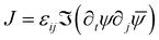
We consider the hydrodynamic model34 that describes the collective dynamics of self-propelled entities in terms of the evolution of the polar order parameter as given by| |  | (1) |
where γ is the rotational viscosity, λ is the flow-aligning parameter43 which aligns the order parameter with the shear rate tensor 2Eij = ∂juj + ∂jui, while the vorticity tensor is 2Ω = (∂iuj − ∂jui), and the free energy favoring the polar order is described as| |  | (2) |
Here, Kp is the isotropic elastic constant for distortions in the polarity field and A is the height of local energy barrier. The polarity is coupled with the flow field u which is described by the incompressible Stokes equations
| | (Γ − η∇3)![[u with combining right harpoon above (vector)]](https://www.rsc.org/images/entities/i_char_0075_20d1.gif) = α0∇·Q − ∇P, = α0∇·Q − ∇P, | (3) |
| | | ∇· = 0, | (4) |
where the active stress is proportional to the nematic tensor
with the proportionality constant given by activity parameter
α0. The incompressibility constraint determines the fluid pressure
P. The viscosity is set by
η while the friction with a substrate is introduced by the frictional drag
Γ.
44 Since we focus on theoretical derivations of the active flows induced by polar and dipolar forces, we hereby neglect the additional passive stresses which depend on the polarity and that are typically present in the Stokes equations simulated numerically.
We consider the dimensionless forms of these equations following the appropriate rescalings in units of length  and time τ = γ/A. The system is then controlled by two dimensionless parameters: the scale number ζ =
 ![[small script l]](https://www.rsc.org/images/entities/char_e146.gif) d/ξ is the ratio between the hydrodynamic dissipation length
d/ξ is the ratio between the hydrodynamic dissipation length  and the nematic coherence length ξ, and the rescaled activity
 ![[small alpha, Greek, tilde]](https://www.rsc.org/images/entities/i_char_e0dc.gif) 0 = α0τ/(ξ2) = α0γ/(Kp). Thus, the dimensionless flow equations read as
0 = α0τ/(ξ2) = α0γ/(Kp). Thus, the dimensionless flow equations read as
| | (1 − ζ2∇2) = ![[F with combining right harpoon above (vector)]](https://www.rsc.org/images/entities/i_char_0046_20d1.gif) a − ∇P, a − ∇P, | (5) |
| | | ∇2P = ∇·a | (6) |
where the dipolar active force induced by the active stress is
| |  | (7) |
For infinite systems, the flow velocity and pressure originated from dipolar active forces can be calculated from convolution integrals of the source terms and the corresponding Green's functions as
| |  | (8) |
and
| |  | (9) |
To derive analytical expressions, we evaluate the source term due to the active stress using the order parameter for an isolated point defect located at the origin and given by
(r,θ) = χ(r)[cos(qθ + ϕ)![[e with combining right harpoon above (vector)]](https://www.rsc.org/images/entities/i_char_0065_20d1.gif) x + sin(qθ + ϕ)y], x + sin(qθ + ϕ)y], |
where
θ = arctan(
y/
x) is the polar angle in a coordinate system centered at the defect position and
χ(
r) is the core function, where we assume that the core size is much smaller than any other length scales and set
χ(
r) = 1. The angle of the polar vector order parameter for an ideal defect is given by
Θ(
θ) =
qθ +
ϕ,
22 where
qθ is the singular part giving the winding number
q when performing the integral ∮d
Θ = 2π
q on a contour surrounding the defect and
ϕ is a constant, giving a baseline phase to the defect. For defects of charge
q ≠ +1 this constant sets the orientation of the defect and can be ignored since we can always transform to a system with
ϕ = 0 by a change of basis. When
q = +1 it is impossible to remove a non-zero
ϕ by changing the basis.
45 The +1 defects have polar symmetry,
i.e. 2π rotational invariance. The intrinsic phase
ϕ is important for distinguishing different types of positive defects:
ϕ = 0 corresponds to an aster and
ϕ = π/2 gives rise to a vortex, and any value in-between corresponds to a spiral defect. For a more intuitive depiction of this, we plot in
Fig. 1(a) and (c) the
field on the circumference of a circle centered at ±1 defects to show that
ϕ corresponds to the constant angle that
makes with the radial direction. For the negative defect one can define a polarisation from the line where
is pointing radially outward from the core, the angle of this polarisation is half of
ϕ. The different patterns of the
field around a ±1 defect are also illustrated in
Fig. 1(b) and (d).
 |
| | Fig. 1 Polarity field around the ±1 topological defects. (a) and (b) Show a +1 defect, while (c) and (d) illustrate a −1 defect. The drawings (a) and (c) show the plotted on a circle with the angle ϕ marked. This illustrates why ϕ can be set to zero by a change of basis for the −1 defect and not for the +1 defect. (b) and (d) Show the polarity fields around a +1 defect with ϕ = π/3 (spiral) and a −1 defect with ϕ = 0 respectively (changing ϕ rotates the negative defect). | |
We use the Halperin–Mazenko formalism46,47 for tracking topological defects as zeros of the polar order parameter to derive the corresponding equations of motion of defects from the evolution of the field similar the approach from ref. 42 to describe orientational defects in active nematic films. The basic idea is that since the ±1 defects are associated simultaneously with topological singularities in the orientation field and zero magnitude of the vector order parameter, we can track their position by Dirac delta functions centered at the zeros of the field. Hence, a configuration of well-separated defects punctuating the -field corresponds to a defect charge density field, which can be written equivalently either as a superposition of the delta functions associated with the topological singularities located in the physical space or as the zeros in the order parameter space,
| |  | (10) |
where
D is the determinant of the polarity distortion tensor ∇
,
i.e. D =
εij∂
ipx∂
jpy which can be expressed equivalently in the complex representation
ψ =
px +
ipy as 2
iD =
εij∂
i![[small psi, Greek, macron]](https://www.rsc.org/images/entities/i_char_e0d9.gif)
∂
jψ. The
D-field is zero in regions of uniform polar order and becomes nonzero where there are distortions in the orientation field. For configurations of well-separated defects punctuating a uniform polar order state, the
D field is zero everywhere except at the defect positions labeled by the index
n, where the topological charge
qn = ±1 is determined by the sign of
D. Thus, the
D field represents a non-singular charge density field.
It can be shown that the D-field follows the conservation law46
| | ∂tD + ∂i![[J with combining right harpoon above (vector)]](https://www.rsc.org/images/entities/i_char_004a_20d1.gif) i = 0, i = 0, | (11) |
with the current density
determined by the evolution of the polar order. Combining this with the conservation of topological charge density
ρ, we can derive a general expression for the defect velocity in terms of the
D and its current,
![[v with combining right harpoon above (vector)]](https://www.rsc.org/images/entities/i_char_0076_20d1.gif) n
n =
/
D|
![[r with combining right harpoon above (vector)]](https://www.rsc.org/images/entities/i_char_0072_20d1.gif) n
n.
42 In the complex representation, we parameterise the polarity field centered on the
n-th defect as
ψ =
ψne
iϕn, where
ϕn is the polarization induced by the
n-th defect and
ϕn is the background phase. Near the defect, the polarization vanishes linearly in magnitude where its phase becomes multivalued. This implies that
ψn = |
−
n|e
iθn, with
θn =
qn![[thin space (1/6-em)]](https://www.rsc.org/images/entities/char_2009.gif)
arctan[(
y −
yn)/(
x −
xn)] being the singular phase.
42,48 Within this approach, the general expression of the defect current density can be reduced to a closed expression for the defect velocity given by
| | | n = (n) + 2qn∇⊥ϕn|=n. | (12) |
Using the stationary phase approximation, i.e. that the constant (equilibrium) phase remains stationary when it is punctuated by moving defect singularities, we can further simplify the defect velocity and express it in terms of the net spontaneous flow and the forces induced by the other defects as42,49
| |  | (13) |
The topological defects interact through Coulomb-like forces, where like-signed defects repel, and opposite-signed defects attract each other. However, there are additional interactions through the flow field
which depends on the dipolar active forces. In the next section, we derive analytic expressions for this flow velocity and discuss its effect on the defect motion.
3 Active flow fields around ±1 topological defects
From the parameterization of the -field for a pointwise defect, we can evaluate the dipolar active force induced by an isolated defect with charge q = ±1 in an otherwise homogeneous polarity field with constant background orientation ϕ as| | 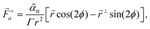 | (14) |
| |  | (15) |
where ⊥ = (y,−x), and R2ϕ is a matrix that rotates the vector by 2ϕ, and can be removed by a change of basis. Notice that the first term in +a is a source of gradient flow, which however is removed by pressure through the incompressibility condition. The second term proportional to sin(2ϕ) is related to a rotated gradient and induces a purely vortical flow.
We insert these forces into the integrals in eqn (8) and (9), and solve them as described in the Supplementary Material.50 The resulting expressions for the active flow velocity and pressure for a +1 defect reduce to
| |  | (16) |
| |  | (17) |
Here
L is a cutoff scale set by the system size. We have written the velocity field as a complex field defined as
u =
ux +
iuy, where
r and
θ are the polar coordinates centered at the defects position. We define the scaled radial coordinate as
![[r with combining circumflex]](https://www.rsc.org/images/entities/i_char_0072_0302.gif)
=
r/
ζ, which is the same as changing the length scale to the hydrodynamic dissipation length
d (see
Fig. 2, with the cutoff scale
L = 50). Notice that the pressure is isotropic and its gradient force cancels the radial component of the dipolar active force, thus no net pressure flow. Furthermore, the corresponding vorticity is also isotropic
| | 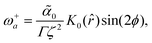 | (18) |
and is non-zero at the centre of the defect as evidenced also in
Fig. 2. This has important consequences for the stability of vortex, spiral, or aster shaped positive defects as discussed in detail in ref.
15. The sign of the global circulation is modulated by the character of the +1 defect through
ϕ.
 |
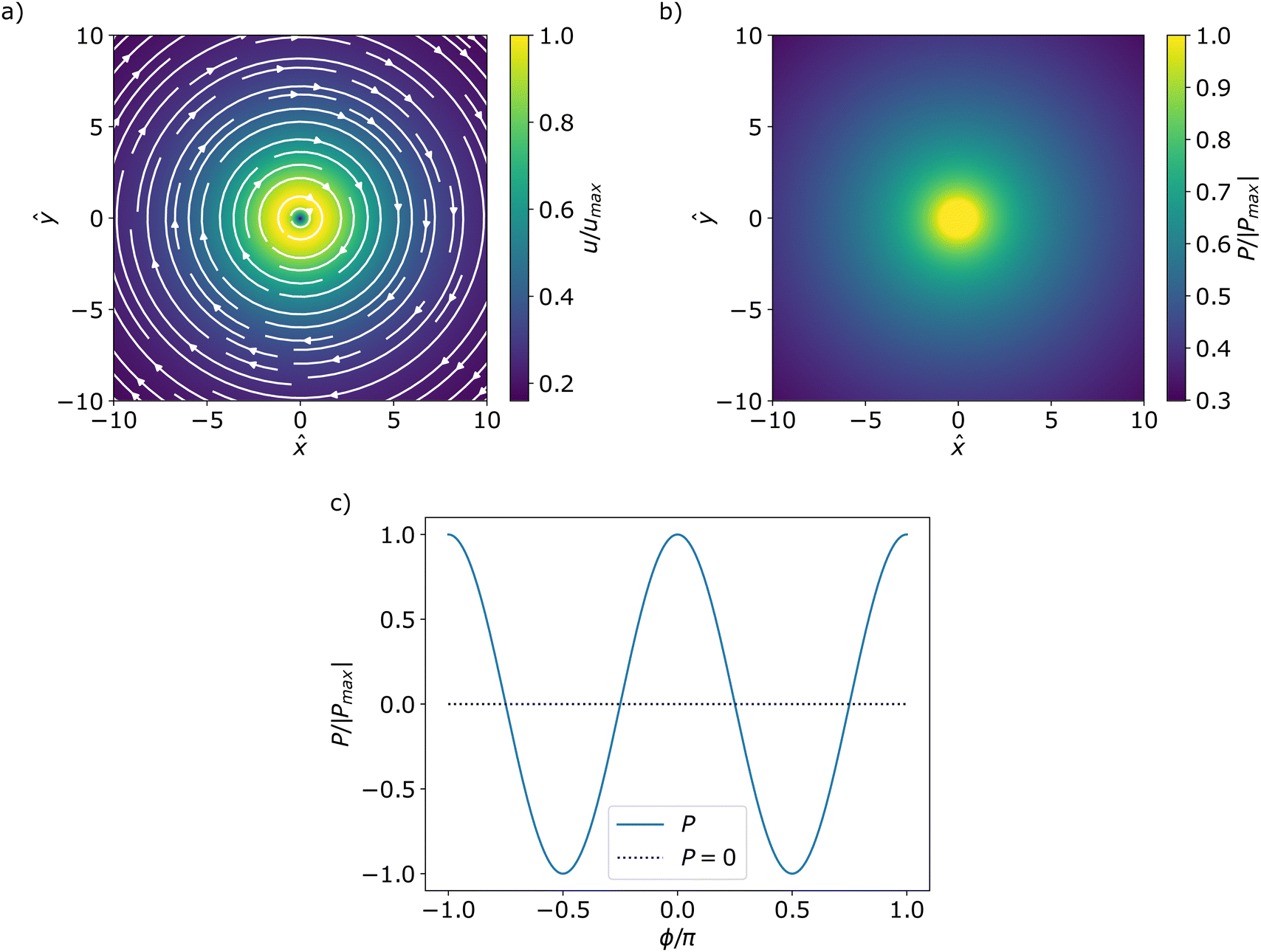
| | Fig. 2 Incompressible active flow streamlines (a) and corresponding pressure field (b) around an isolated +1 defect with sin(2ϕ) > 0 in an extensile (0 < 0) system. The colormap shows the magnitude of the velocity and pressure normalized by their maximum. Note that the pressure in the far-field diverges with the system size L. Since the pressure diverges at the centre the pressure inside the core r < 1 has been set to the value at r = 1. This is also the value that is used for the normalization. (c) Shows the normalised pressure, for an extensile system, at a fixed radius as a function of ϕ. Notice that for ϕ = ±π/4 + πn the pressure vanishes. | |
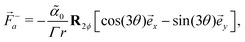
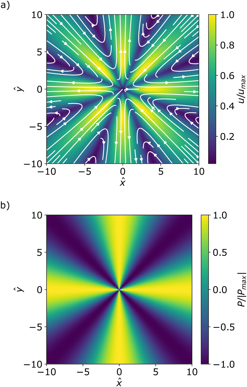
Similarly, we find analytical expressions for the active flow velocity, pressure and vorticity related to the −1 defect, which are written in a compact form as
| | 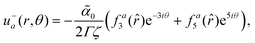 | (19) |
| |  | (20) |
| |  | (21) |
The functions
fa3,
fa5, and
faω giving the radial dependence of the velocity and vorticity are listed in the Appendix. This velocity and pressure fields are also plotted in
Fig. 3 showing that while the positive defect has closed streamlines also in an infinite system, the negative defect has an 8-fold symmetry of the vorticity, underlying a 4-fold symmetry of the polarity field around the defect. The streamlines do not close in an infinite system, but in confinement they might close due to boundary conditions or influence from other defects similarly to the vortices formed around ±1/2 defects in an active nematic.
21,51 It is important to note the distinctions of the analytical descriptions provided herein with a recent calculations of compressible flow fields inside circular confinements.
41 In the latter, the analyses is restricted to circular domains with radius smaller than the coherence length
R2 ≪
Kp/
A,
i.e. the limit where relaxation/penetration length in the free energy is larger than the system size. Those results are therefore in the opposite limit of the calculation performed here.
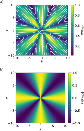 |
| | Fig. 3 Incompressible active flow streamlines (a) and corresponding pressure field (b) around an isolated −1 defect with ϕ = 0 in an extensile (0 < 0) system. The colormaps show the normalised magnitude of velocity (a) and pressure (b). | |
In addition to the characteristic flow fields, our closed form analytic descriptions provide an insight into the isotropic stress patterns, i.e., half of the trace of the stress tensor, around full-integer topological defects. Such isotropic stresses have been shown to be a determining factor for the biological functionality of nematic defects, where concentration of compressive stress around +1/2 defects was shown to lead to cell death and extrusion,28 while the tensile stresses around −1/2 defects has been shown to lead to spontaneous gap opening in epithelial cell layers.52 Similarly, we find distinct isotropic stress patterns around positive and negative full-integer defects: while around a negative (−1) defect alternating regions of tension and compression appear in a 4-fold symmetric pattern (Fig. 3b), a strong augmentation of compressive stress is observed at the core of positive +1 defects (Fig. 2b). We conjecture that such a concentrated compressive stress at +1 defects could contribute to the activation of mechanosensitive signals in cell layer and potentially be linked to the recent observation of the cellular differentiation at +1 defect cores in cartilage cells.53
3.1 Vortical flow reversal around +1 defect
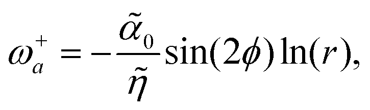
The results presented above provide closed-form analytical expressions for incompressible flows around full-integer topological defects in polar active matter. Interestingly, in the absence of friction (Γ = 0), we predict that the vortical active flow around the +1 defect changes chirality on a lengthscale comparable with the coherence length outside of the defect core, thus the flow reversal is a near-defect behavior.
Note that that zero friction is a singular limit and the resulting flow equations have no natural lengthscale. Thus the rescaling is done with an appropriate lengthscale coming from the free energy, such as the coherence length. In this limit, the active flow velocity can be derived (details in the ESI†) to be on this form
| | 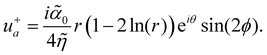 | (22) |
The corresponding vorticity acquires logarithmic dependence with the distance from the defect
| | 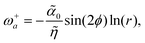 | (23) |
where
![[small eta, Greek, tilde]](https://www.rsc.org/images/entities/i_char_e110.gif)
=
η/
ξ2. We notice that the vorticity changes handedness for

(in coherence length), giving rise to two concentric, counter-rotating flows, as shown in
Fig. 4.
 |
| | Fig. 4 (a) Streamlines of the theoretical active flow around an isolated +1 defect for sin(2ϕ) > 0 for an extensive system and Γ = 0. The colormap shows the flow magnitude normalized by its largest value in the plotted domain. The change in color of the streamlines from white to black highlight the flow reversal at r ≈ 1.7. This is more apparent in (b) which is a cross section of the azimuthal velocity component along the positive x axis. The velocity changes sign when it crosses the zero line. | |
Notice also that the flow diverges at r → ∞ due to no screening lengthscale and at r → 0 without adding a core size regularization in the integral solutions. We predict that the flow reversal is a near defect core effect when the far-field boundary conditions generate an opposite torque and disappears in the presence of hydrodynamic screening effects. The Green functions correspond to the homogeneous Dirichlet boundary conditions in an infinite domain. The mathematical reason for this flow reversal is that the logarithmic Greens function changes sign when r < 1 in units of the coherence length, unlike the Bessel function K0 which maintains the same sign on lengthscales larger than the hydrodynamic screening length. The flow reversal on a lengthscale comparable with the core size is validated in numerical simulations and this suggests that mutual defect interactions are not important for this near-defect flow changes as long as defects are well-separated.
Similar flow reversal is also present in systems confined to circular domains that are small enough such that the energy scale can be treated as linearly dependent on the radial distance from the center of singularity χ(r) ∼ r in the entire domain.41 For such systems the flow reversal happens inside the core region.
3.2 Comparison with numerical simulations
Here we discuss the comparison of the analytical predictions of active flow induced by ±1 defects with those obtained from direct numerical simulations of the polarization evolution eqn (1) and (2) coupled with the Navier–Stokes equations| |  | (24) |
with the additional passive stresses σp = σvisp + σelp as defined in ref. 34 and 54, including the viscous stress σvisp = 2ηE, and the elastic stress 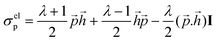 , where
 ![[h with combining right harpoon above (vector)]](https://www.rsc.org/images/entities/i_char_0068_20d1.gif) = ∂F/∂ is the molecular field.
= ∂F/∂ is the molecular field.
For numerical simulations, we use a hybrid lattice-Boltzmann method, combining finite-difference for the evolution of polarity and the lattice-Boltzmann method for that of velocity55 (more details in the Appendix). Using the same prescription as in ref. 35 for density and viscosity, i.e. ρ = 40 and η = 3.6, we ensure that the Reynolds number in the simulations remains negligible (Re ≪ 1)18,56 so that the dynamics of velocity virtually reduces to the incompressible Stokes equations eqn (3) and (4) considered here. We fix the viscosity ratio to η/γ = 3.6, micro to macro length scale to  (assuring that the coherence length
  is significantly smaller than the domain size L), and the flow alignment parameter to λ = 0.1. Dimensionless parameters in the simulations are defined similar to the theoretical parameters defined in Section 2.
Simulations were initialized with quiescent velocity field and noisy polar alignments close to the uniformly oriented state = x under periodic boundary conditions, on square domains of linear dimension L = 256. We consider sufficiently large values of the activity parameter 0 = ±1 such that topological defects to form spontaneously.35 For each simulation, we average the individual flow profiles in the vicinity of each defect over an ensemble of defects (ranging from ≃102 to ≃103). Because every defect has its own orientation, we have to carefully reorient the defects and the flows as described below.
We define the orientation of −1 defects from the surrounding polarization field . Given the 4-fold symmetry of the −1 defect (see Fig. 1(d)), we search for the two principal axes along which the vector points inwards and outwards, respectively, and rotate the local fields so the principal axes align.
For +1 defects, the baseline (intrinsic) phase ϕ plays an important role in distinguishes among vortices, asters and spirals and their orientation (see Fig. 1). We ensemble-average the vortical flow profile for these different types of +1 defects. For this, we identify the flow chirality of a +1 defect, by computing the sign of the circulation  along a contour C centered on the defect and with a radius smaller than the lengthscale of the flow reversal. For defects with clockwise flow chirality
  the local polarization and velocity profiles are reversed, while for those with counterclockwise flow chirality, the fields are kept with the same orientation, so that all fields are consistently averaged.
The numerical results of the average polarization and flow around aster-like and vortex-like defects are shown in Fig. 5, and around −1 defects are presented in Fig. 6. For both types of defects, the average polarization (right panels in Fig. 5 and 6) has the same rotational symmetries as those corresponding to the polarity director in Fig. 1. However, we also notice that the magnitude of the average polarization varies with the distance to the defect and localises into different patterns, i.e. a halo around the +1 defect as in Fig. 5 and a “cross”-like pattern for the −1 defect as in Fig. 6. This cross pattern aligns with the principal axes of the 4-fold polarity director for contractile systems (![[small alpha, Greek, macron]](https://www.rsc.org/images/entities/i_char_e0c2.gif) 0 > 0) and is rotated by π/4 for extensile systems (0 < 0) following the inward/outward flow directions. The average flow profile around a −1 defect has the 8-fold rotational symmetry as theoretically predicted for an isolated defect and appears both for extensile and contractile systems as shown in Fig. 6.
0 > 0) and is rotated by π/4 for extensile systems (0 < 0) following the inward/outward flow directions. The average flow profile around a −1 defect has the 8-fold rotational symmetry as theoretically predicted for an isolated defect and appears both for extensile and contractile systems as shown in Fig. 6.
 |
| | Fig. 5 Numerical average polarization and velocity profile around representative +1 aster-like (a) and (b) and vortex-like defects (c) and (d). Colormaps are scaled by the maximum magnitude in polarization and flow velocity, respectively. Averages are computed for ensembles of ≃400 defects as discussed in the Appendix (Fig. 11). Similar average profiles for lower activity are shown in Fig. 12. | |
 |
| | Fig. 6 Numerical average of the polarization and velocity fields around −1 defects, for various activities 0. Colormaps are scaled by the maximum magnitude in polarization and flow velocity, respectively. For 0 = ±1, averages are computed from the same simulations as for +1 defects in Fig. 5, but for a larger ensemble of ≃1000 defects, since all −1 defects are of the same type. For the lower activity 0 = ±0.4, averages are computed for smaller ensembles of ≃100 defects. | |
We now discuss the numerical results on the average vortical flows generated by aster-like and vortex-like defects in relation to our theoretical prediction (Fig. 2 and 4). As shown in Fig. 5, we see the predicted flow reversal emerges robustly on the ensemble-average profiles. The counterclockwise flow direction close to the defect is a result of our averaging procedure. Given that the vortical flow reverses its chirality near the defect cores on a statistical level as theoretically predicted for an isolated defect suggests that collective defect interactions are not crucial for this effect.
3.3 Defect pair interaction modulated by dipolar active forces
As seen in the above section, the dipolar active force does not lead to any defect self-propulsion for isolated ±1 defects in an infinite domain. We now consider a pair of ±1 defects and show that the dipolar active force leads to an interaction between them through the active flow. For analytic tractability, we consider the friction-dominated regime Γ ≫ η and set the viscosity to zero, d → 0. The defect velocity is calculated using the methods from ref. 42 (see ref. 50 for details) and is given by| |  | (25) |
| |  | (26) |
for the +1 defect and −1 defect, respectively. Here Λ is a regularising lower cut-off corresponding to the finite defect core due to the divergent pressure at the +1 defect. R is the distance between the defects, φ is the angle of ![[R with combining right harpoon above (vector)]](https://www.rsc.org/images/entities/i_char_0052_20d1.gif) = − − +. ϕ is the uniform background orientation field. This effective interaction induced by dipolar active forces decays inversely proportional with the distance between defects similar to the Coulomb-like force induced by the phase gradients alone. However, these interactions are anisotropic since they depend on the orientation of the background polarization as well as the orientation of the defect pair.
= − − +. ϕ is the uniform background orientation field. This effective interaction induced by dipolar active forces decays inversely proportional with the distance between defects similar to the Coulomb-like force induced by the phase gradients alone. However, these interactions are anisotropic since they depend on the orientation of the background polarization as well as the orientation of the defect pair.
4 The effect of polar active forces
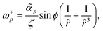
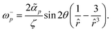
Next, we also include the polar active force in the flow equations eqn (5) and study its contribution to the flow velocity up and pressure Pp. In dimensionless units, the polar active force iswhere p = αpτ/(ξΓ) is a rescaled parameter that measures the strength of polar active forces relative the frictional drag. We consider αp > 0 corresponding to polar particles moving in the direction of their head. The corresponding flow velocity and pressure fields can now be written compactly as (see details in SM50)| | u+p(,θ) = ipeiθ![[thin space (1/6-em)]](https://www.rsc.org/images/entities/i_char_2009.gif) sin(ϕ)fp1(), sin(ϕ)fp1(), | (28) |
| | | P+p(r,θ) = prcos(ϕ), | (29) |
| |  | (30) |
| |  | (31) |
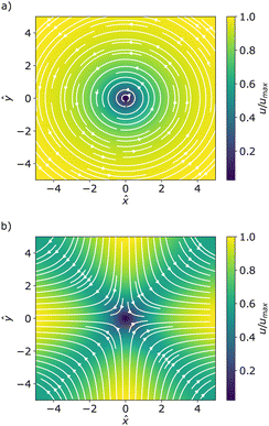
for the positive and the negative defect respectively. The velocity profiles are plotted in the Fig. 7 while the functions f1 and f3 are plotted in Fig. 8 together with their asymptotic values. It is straightforward to show that both f1 and f3 tend to zero at the defect origin, thus the polar active forces do not contribute to defect self-induced motility. It is important to note that the flow induced by polar active forces around the +1 defect is proportional to sin(ϕ), instead of the sin(2ϕ) dependence that was found for the flow induced by dipolar active forces eqn (16). This means that while the polar active forces do not produce any flow around an ideal aster (ϕ = 0), there will be a polar activity-induced flow around an ideal vortex (ϕ = π/2). Furthermore, eqn (29) shows that the pressure is proportional to the radial distance ∼r, indicating that, in the absence of any far-field screenings from other defects, the pressure can become quite large. This is related to the flow induced by polar active forces being constant in magnitude in the fare-field, as illustrated in Fig. 8, or by explicitly writing the asymptotic limits| | 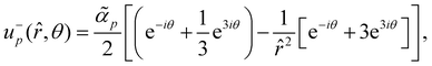 | (32) |
| |  | (33) |
for the negative and positive defect, respectively. As we will show explicitly for a pair of defects in the next section, eqn (32) and (33), together with eqn (13), indicate that there are strong interactions between defects regardless of the distance between them.
 |
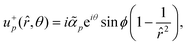
| | Fig. 7 Velocity streamlines due to polar active forces for (a) the positive defect (vortex flow) and (b) the negative defect (saddle-point flow). Colormap represents the magnitude of the velocity field normalized by its maximum value. | |
 |
| | Fig. 8 Plot of the functions (blue, whole lines) fp1 (a) and fp3 (b) against their asymptotic limits (black, doted lines) as given in eqn (32) and (33). Note that the functions asymptotically approach to non-zero values in the far-field. | |
From the closed form formulas of the flow velocity around the defects, the far-field vorticity induced by the +1 defect can be calculated as
| |  | (34) |
and, for the −1 defect, this is
| |  | (35) |
Interestingly the vorticity of the +1 defect is independent on the baseline/intrinsic angle
θ, which is also true in the near-field, because we can write the velocity field in the form
=
⊥f(
r). As such, close to the defect center the vorticity of the negative defect vanishes at the center, while the positive defects has a finite vorticity
| | 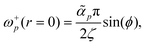 | (36) |
indicating that the +1 defect acquire a rotational motion in addition to their translational motion.
4.1 Defect-pair interaction in friction-dominated system
Taking again the analytically tractable limit of zero viscosity, we can find the velocity induced by polar active forces for a pair of oppositely-charged defects following the approach from Section 3.3. The flow velocities in the centre of the ±1 defects reduce to| |  | (37) |
| | 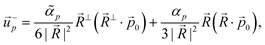 | (38) |
where = − − + is the separation vector between the negative defect and the positive one, and 0 = cos(ϕ)x + sin(ϕ)− is the uniform background polarity. Interestingly, the polar active forces induce non-reciprocal and non-local mutual interactions that depend only on the orientation of relative to ϕ, independent of the separation distance R between the defects. This suggests a truly long-ranged interaction between oppositely-charged defects in the presence of polar active forces.
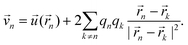
Furthermore, the −1 defect tends to move towards/away from + 1 depending on the orientation angle of with respect to . Both defects move perpendicular to but at different rates inducing the pair to rotate. We can see this behavior more clearly by looking at the defect pair velocity under polar active forces alone,  given by
| |  | (39) |
where the first term (‖
) is an attraction/repulsion force between the defects, while the second term (⊥
) rotates the defect pair. The rotation is zero, when the defect pair aligns with the background polarization in either directions (
‖
0). We show in SM.
50 that the defect pair rotates until annihilation, unless
is initially parallel to
0. For initial orientations where
·
0 > 1, the defects first move a part while re-orientating such that they attract each other. Namely, as long as
⊥·
0 ≠ 0, the separation vector
will rotate until
·
0 becomes negative and the defects move toward each other (see SM
50 for the derivation). The rate of defect annihilation is thus dependent on the initial orientation. This shows that the polar active force leads to pair annihilation of oppositely-charged defects to promote large-scale polar order.
To check this dynamics numerically, we compare the pair trajectory determined by eqn (13) with that predicted by the full hydrodynamic model from integrating eqn (1), (3) and (4) with the same initial configuration. The initial uniform polarisation = y is seeded with a defect pair in the x-direction, i.e. − = −20y and + = −20x, such that ⊥0 at t = 0. The model parameters are set to p = 0.5, 0 = 0, λ = 0 and ζ2 = 0.01. The hydrodynamic equations are solved with periodic boundary conditions in a domain 256 × 256 with a spatial discretisation Δ = 0.5, using spectral methods and an exponential time differentiation scheme.57 Under the polar active force, the separation vector rotates relative to 0, and this changes the shape of the +1 defect from an initial vortex to an aster at the annihilation time. This effect is lost in the absence of polar active forces, i.e. at p = 0 (see animations of the defect pair annihilation in ref. 50).
The two trajectories are shown in Fig. 9(a) and agree very well for large R = || in consistency with the pointwise approximation. It also shows that polar active forces increase the annihilation rate. This is further evidenced in Fig. 9(b) where we compare the evolution of the separation distance R(t) when the two defects interact through the Coulomb-like forces with or without the presence of polar active forces. At p = 0, R(t) decreases in the far-field as  (t0 being the annihilation time) due to the 1/R interaction forces. However, for p ≠ 0, the annihilation timescale is greatly reduced and the deviations from the
  behavior arise due the non-local and non-reciprocal attraction force. The rotation rate is also contributing to aligning the defects to increase the attraction between the defects.
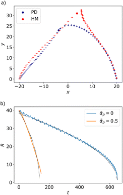 |
| | Fig. 9 (a) Phase portraits of the defect pair trajectory obtained from (blue) the kinematics of point defects (PD) from eqn (13), and (red) by direct simulation of the hydrodynamic model (HM) with identical initial condition of the defect pair at ± = ±20x with the homogeneous background polarization being 0 = y. The +1 defect is marked by +, the −1 by −. p = 0.5, 0 = 0, λ = 0 and ζ2 = 0.01. (b) Distance R between a defect pair as a function of time for Coulomb-like interactions only (blue curve) and in the presence of polar active forces (orange curve). The black doted lines are fitting curves with the  found by linear regression on R2. found by linear regression on R2. | |
5 Discussion/conclusion
In summary, we present theoretical derivations of incompressible flow fields and dynamics of ±1 defects under dipolar and polar active forces. These active forces do not endow the full-integer defects with any self-propulsion, as expected from the symmetry of the defects. However, the +1 defect acquires a non-zero active torque due to both polar and dipolar active forces. We show that the strength of this spin is dependent on whether the defect is a vortex, aster or spiral. In the absence of hydrodynamic screening due to friction, the vortical active flow around a +1 vortex changes sign on a length scale set by the coherence length as observed in numerical simulations and predicted analytically. For both defects, the dipolar active force contribution to the flow field vanishes with 1/r in the defect far-field, whereas the polar active force contribution approach a constant value. Remarkably, polar active forces mediate mutual interaction between oppositely-charged defect pairs in a manner that renders defect-defect interactions independent of the distance between the defect pair. We have shown that, under these polar active forces, a pair of oppositely-charged defects rotates to align with the background polarization field, while the negative defect chases the positive one until annihilation. The rate of annihilation is greatly enhanced by polar active forces, and this is the main underlying mechanism for the suppression of defect-laden active turbulence in polar active matter as reported numerically in ref. 35. This effect of polar active forces has been studied so far for flat surfaces. It would be interesting to explore this effect further for curved surfaces where additional topological constraints are present.24,58
Author contributions
J. Rø contributed with analytical derivations, numerical simulations, visualisation and data analysis. J. Re contributed with lattice-Boltzmann simulations, visualisation and data analysis. A. D. and L. A. formulated the project and contributed with supervision. A. D. provided computational resources. L. A. checked the analytical calculations. All authors contributed with drafting and writing the manuscript.
Conflicts of interest
There are no conflicts to declare.
Appendices
A1. Analytical expression of the functions defining the active flow fields
Here we write down the radially-dependent functions associated with the flow fields induced by polar and dipolar active forces. Derivation details are found in the SM.50 The radial functions for the dipolar active flow velocity are:| |  | (40) |
| |  | (41) |
The radial function for the corresponding vorticity field| |  | (42) |
The radial functions for the polar active flow velocity are:| |  | (43) |
and| |  | (44) |
Where ψ(0) is the digamma function. The coefficients of the infinite power series are| | 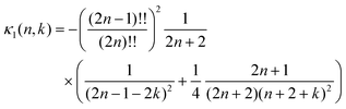 | (45) |
| | 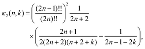 | (46) |
| | 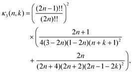 | (47) |
| | 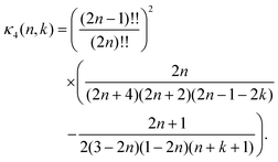 | (48) |
Note that when summing over n the coefficients κ4(n,k) tends to zero for any k. The infinite series are convergent, but slowly.
A2. Details on the numerical simulations
Numerical and modeling framework.
We solve the hydrodynamic model eqn (1) and (2) using a hybrid lattice-Boltzmann and finite difference method34,35,55 with periodic boundary conditions on square domains L × L of size L = 256. All simulations are run for model parameters set to Kp = 0.04, A = 0.01, γ = 1, λ = 0.1. This fixes the rescaling units, i.e. the nematic coherence length  and a characteristic time τ = γ/A = 100. We also fix the shear viscosity such that η/γ = 3.6, and the density to ρ = 40, thus ensuring that the Reynolds number in the simulation remains negligible (Re ≪ 1)18,56 and that the dynamics of velocity virtually reduces to the incompressible Stokes equations eqn (3) and (4) considered here. We then run simulations in the frictionless regime (Γ = 0), for four different values of activity, namely α0 ∈ {−1, −0.4, +0.4, +1}. In the discretisation scheme, we use the space unit Δx = 1 and time increment Δt = 1 for the set values of the model parameters.
Simulations were initialized with a quiescent velocity field and noisy, but reproducible polar alignments close to the uniformly oriented state = x, using know random seeds. To collect the individual flow and polarity fields for the ensemble averages, we save a 100 frames with fixed sampling time ns = 200, excluding the first 40 frames to discard early transients from the analysis. In Fig. 10, we illustrate the flow and polarization pattern around individual defects. The pattern of the polarization field (right panels) is aster-like (top) or vortex-like (bottom). We notice that the individual flow profile (left panels) is highly fluctuating while the vortical flow pattern emerges upon averaging out these fluctuations. We identify the type of the topological defect by the circulation of the polarization around the defect as illustrated in Fig. 11(a) and plot them in the phase space of the polarization vector corresponding to the unit disk D1 as shown in panel (b). Panels (c) and (d) represent the distributions of the +1 defects from the two of our simulations with 0 = ±1 showing that for extensile systems (0 < 0) most defects are vortex-like, while for contractile ones (0 > 0) there are mostly aster-like defects. We group the defects accordingly to compute the average fields shown in Fig. 5, after assessing the flow chirality as described in the main text. A similar analysis is carried out for smaller activity 0 = ±0.4 and shown in Fig. 12.
 |
| | Fig. 10 Velocity and polarisation fields in the vicinity of individual (+1) defects for 0 = +1. | |
 |
| | Fig. 11 Distribution of +1 defects in the phase space of polarization given by the D1 disk. | |
 |
| | Fig. 12 Analysis of the flow and polarization profile around +1 defects for 0 = ±0.4. | |
Simulation platform.
We ran all our simulations on Copenhagen University HPC (High-Performance-Computing) cluster, using the collaborative MASS (Many Active Systems Simulations) program, on which several labs in Europe actively collaborate. This program takes a model definition as an input, under the form of a C++ file, along with a runcard (.dat file) specifying the values to assign to the different parameters.
Acknowledgements
J. Rø and L. A. acknowledge support from the Research Council of Norway through the Center of Excellence funding scheme, Project No. 262644 (PoreLab). A. D. acknowledges funding from the Novo Nordisk Foundation (grant No. NNF18SA0035142 and NERD grant No. NNF21OC0068687), Villum Fonden Grant no. 29476, and the European Union via the ERC-Starting Grant PhysCoMeT. Views and opinions expressed are however those of the authors only and do not necessarily reflect those of the European Union or the European Research Council. Neither the European Union nor the granting authority can be held responsible for them.
Notes and references
- A. Doostmohammadi, J. Ignés-Mullol, J. M. Yeomans and F. Sagués, Nat. Commun., 2018, 9, 1–13 CrossRef CAS PubMed.
- M. C. Marchetti, J.-F. Joanny, S. Ramaswamy, T. B. Liverpool, J. Prost, M. Rao and R. A. Simha, Rev. Mod. Phys., 2013, 85, 1143 CrossRef CAS.
- C. Blanch-Mercader, V. Yashunsky, S. Garcia, G. Duclos, L. Giomi and P. Silberzan, Phys. Rev. Lett., 2018, 120, 208101 CrossRef CAS PubMed.
- S.-Z. Lin, W.-Y. Zhang, D. Bi, B. Li and X.-Q. Feng, Commun. Phys., 2021, 4, 1–9 CrossRef.
- T. Sanchez, D. T. Chen, S. J. DeCamp, M. Heymann and Z. Dogic, Nature, 2012, 491, 431–434 CrossRef CAS PubMed.
- P. Guillamat, J. Ignés-Mullol and F. Sagués, Nat. Commun., 2017, 8, 1–8 CrossRef CAS PubMed.
- D. Needleman and Z. Dogic, Nat. Rev. Mater., 2017, 2, 17048 CrossRef CAS.
- N. Kumar, R. Zhang, J. J. de Pablo and M. L. Gardel, Sci. Adv., 2018, 4, eaat7779 CrossRef CAS PubMed.
- A. Kudrolli, G. Lumay, D. Volfson and L. S. Tsimring, Phys. Rev. Lett., 2008, 100, 058001 CrossRef PubMed.
- K. Kruse, J.-F. Joanny, F. Jülicher, J. Prost and K. Sekimoto, Eur. Phys. J. E: Soft Matter Biol. Phys., 2005, 16, 5–16 CrossRef CAS.
- J. Toner and Y. Tu, Phys. Rev. Lett., 1995, 75, 4326 CrossRef CAS PubMed.
- F. Juelicher, K. Kruse, J. Prost and J.-F. Joanny, Phys. Rep., 2007, 449, 3–28 CrossRef CAS.
- L. Giomi, M. J. Bowick, X. Ma and M. C. Marchetti, Phys. Rev. Lett., 2013, 110, 228101 CrossRef PubMed.
- S. Ramaswamy, R. A. Simha and J. Toner, Europhys. Lett., 2003, 62, 196 CrossRef CAS.
- K. Kruse, J.-F. Joanny, F. Jülicher, J. Prost and K. Sekimoto, Phys. Rev. Lett., 2004, 92, 078101 CrossRef CAS PubMed.
- R. A. Simha and S. Ramaswamy, Phys. Rev. Lett., 2002, 89, 058101 CrossRef.
- S. P. Thampi, R. Golestanian and J. M. Yeomans, Philos. Trans. R. Soc., A, 2014, 372, 20130366 CrossRef.
- A. Doostmohammadi, T. N. Shendruk, K. Thijssen and J. M. Yeomans, Nat. Commun., 2017, 8, 1–7 CrossRef PubMed.
- S. Chandragiri, A. Doostmohammadi, J. M. Yeomans and S. P. Thampi, Phys. Rev. Lett., 2020, 125, 148002 CrossRef CAS PubMed.
- L. Giomi, M. J. Bowick, X. Ma and M. C. Marchetti, Phys. Rev. Lett., 2013, 110, 228101 CrossRef PubMed.
- J. Rønning, C. M. Marchetti, M. J. Bowick and L. Angheluta, Proc. R. Soc., A, 2022, 478, 20210879 CrossRef PubMed.
-
P. M. Chaikin and T. C. Lubensky, Frontmatter, Cambridge University Press, 1995, pp. i–vi Search PubMed.
- A. Doostmohammadi and B. Ladoux, Trends Cell Biol., 2021, 32(2), 140–150 CrossRef PubMed.
- S. Shankar, A. Souslov, M. J. Bowick, M. C. Marchetti and V. Vitelli, Nat. Rev. Phys., 2022, 4, 380–398 CrossRef.
- S. J. DeCamp, G. S. Redner, A. Baskaran, M. F. Hagan and Z. Dogic, Nat. Mater., 2015, 14, 1110–1115 CrossRef CAS.
- G. Duclos, C. Blanch-Mercader, V. Yashunsky, G. Salbreux, J.-F. Joanny, J. Prost and P. Silberzan, Nat. Phys., 2018, 14, 728–732 Search PubMed.
- O. J. Meacock, A. Doostmohammadi, K. R. Foster, J. M. Yeomans and W. M. Durham, Nat. Phys., 2021, 17, 205–210 Search PubMed.
- T. B. Saw, A. Doostmohammadi, V. Nier, L. Kocgozlu, S. Thampi, Y. Toyama, P. Marcq, C. T. Lim, J. M. Yeomans and B. Ladoux, Nature, 2017, 544, 212–216 CrossRef CAS.
- G. Duclos, C. Erlenkämper, J.-F. Joanny and P. Silberzan, Nat. Phys., 2017, 13, 58–62 Search PubMed.
- C. Malinverno, S. Corallino, F. Giavazzi, M. Bergert, Q. Li, M. Leoni, A. Disanza, E. Frittoli, A. Oldani and E. Martini,
et al.
, Nat. Mater., 2017, 16, 587–596 CrossRef CAS PubMed.
- A. Baskaran and M. C. Marchetti, Phys. Rev. E, 2008, 77, 011920 CrossRef PubMed.
- A. Baskaran and M. C. Marchetti, J. Stat. Mech.: Theory Exp., 2010, 2010, P04019 Search PubMed.
- A. Baskaran and M. C. Marchetti, Eur. Phys. J. E: Soft Matter Biol. Phys., 2012, 35, 1–8 CrossRef PubMed.
- A. Amiri, R. Mueller and A. Doostmohammadi, J. Phys. A: Math. Theor., 2022, 55, 094002 CrossRef.
- B. H. Andersen, J. Renaud, J. Rønning, L. Angheluta and A. Doostmohammadi, Phys. Rev. Fluids, 2023, 8, 063101 CrossRef.
- A. Ardaševa and A. Doostmohammadi, Nat. Rev. Phys., 2022, 4, 354–356 CrossRef.
- P. Guillamat, C. Blanch-Mercader, G. Pernollet, K. Kruse and A. Roux, Nat. Mater., 2022, 21, 588–597 CrossRef CAS PubMed.
- T. Brandstätter, D. B. Brückner, Y. L. Han, R. Alert, M. Guo and C. P. Broedersz, Nat. Commun., 2023, 14, 1643 CrossRef PubMed.
-
T. H. Tan, A. Amiri, I. Seijo-Barandiarán, M. F. Staddon, A. Materne, S. Tomas, C. Duclut, M. Popovic, A. Grapin-Botton and F. Jülicher, bioRxiv, 2022, preprint, DOI:10.1101/2022.09.29.510101.
- Y. Maroudas-Sacks, L. Garion, L. Shani-Zerbib, A. Livshits, E. Braun and K. Keren, Nat. Phys., 2021, 17, 251–259 Search PubMed.
- C. Blanch-Mercader, P. Guillamat, A. Roux and K. Kruse, Phys. Rev. E, 2021, 103, 012405 CrossRef CAS PubMed.
- L. Angheluta, Z. Chen, M. C. Marchetti and M. J. Bowck, New J. Phys., 2021, 23, 033009 CrossRef CAS.
- S. Chandragiri, A. Doostmohammadi, J. M. Yeomans and S. P. Thampi, Soft Matter, 2019, 15, 1597–1604 RSC.
- A. Doostmohammadi, M. F. Adamer, S. P. Thampi and J. M. Yeomans, Nat. Commun., 2016, 7, 1–9 Search PubMed.
- X. Tang and J. V. Selinger, Soft Matter, 2017, 13, 5481–5490 RSC.
- G. F. Mazenko, Phys. Rev. Lett., 1997, 78, 401 CrossRef CAS.
-
B. Halperin, proceedings of Les Houches, Session XXXV 1980 NATOASI, ed. R. Balian, M. Kléman and J.-P.Poirier, published in Physics of Defects, 1981 Search PubMed.
-
L. M. Pismen
et al.
, Vortices in nonlinear fields: From liquid crystals to superfluids, from non-equilibrium patterns to cosmic strings, Oxford University Press, 1999, vol. 100 Search PubMed.
-
F. Vafa, M. J. Bowick, M. C. Marchetti and B. I. Shraiman, 2020, arXiv:2007.02947.
- ESI, https://github.com/jonasron/SM_Flowfield_Polar.
- L. Giomi, M. J. Bowick, P. Mishra, R. Sknepnek and M. Cristina Marchetti, Philos. Trans. R. Soc., A, 2014, 372, 20130365 CrossRef PubMed.
- S. Sonam, L. Balasubramaniam, S.-Z. Lin, Y. M. Y. Ivan, I. Pi-Jaumà, C. Jebane, M. Karnat, Y. Toyama, P. Marcq and J. Prost,
et al.
, Nat. Phys., 2022, 1–10 Search PubMed.
-
E. Makhija, Y. Zheng, J. Wang, H. R. Leong, R. B. Othman, E. X. Ng, E. H. Lee, L. Tucker-Kellogg, Y. H. Lee and H. Yuet al., bioRxiv, 2022.
- J. Prost, F. Jülicher and J. F. Joanny, Nat. Phys., 2015, 11, 111–117 Search PubMed.
- D. Marenduzzo, E. Orlandini, M. E. Cates and J. M. Yeomans, Phys. Rev. E: Stat., Nonlinear, Soft Matter Phys., 2007, 76, 031921 CrossRef CAS PubMed.
- S. P. Thampi, R. Golestanian and J. M. Yeomans, EPL, 2014, 105, 18001 CrossRef.
- S. M. Cox and P. C. Matthews, J. Comput. Phys., 2002, 176, 430–455 CrossRef CAS.
- F. C. Keber, E. Loiseau, T. Sanchez, S. J. DeCamp, L. Giomi, M. J. Bowick, M. C. Marchetti, Z. Dogic and A. R. Bausch, Science, 2014, 345, 1135–1139 CrossRef CAS PubMed.
|
| This journal is © The Royal Society of Chemistry 2023 |
Click here to see how this site uses Cookies. View our privacy policy here. 
 Open Access Article
 This Open Access Article is licensed under a
  a,
Julian
Renaud
bc,
Amin
Doostmohammadi
a,
Julian
Renaud
bc,
Amin
Doostmohammadi


 with the proportionality constant given by activity parameter α0. The incompressibility constraint determines the fluid pressure P. The viscosity is set by η while the friction with a substrate is introduced by the frictional drag Γ.44 Since we focus on theoretical derivations of the active flows induced by polar and dipolar forces, we hereby neglect the additional passive stresses which depend on the polarity and that are typically present in the Stokes equations simulated numerically.
 and time τ = γ/A. The system is then controlled by two dimensionless parameters: the scale number ζ =
  and the nematic coherence length ξ, and the rescaled activity


 determined by the evolution of the polar order. Combining this with the conservation of topological charge density ρ, we can derive a general expression for the defect velocity in terms of the D and its current,


 (in coherence length), giving rise to two concentric, counter-rotating flows, as shown in Fig. 4.


 , where
  (assuring that the coherence length
 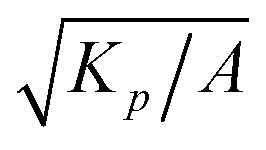 is significantly smaller than the domain size L), and the flow alignment parameter to λ = 0.1. Dimensionless parameters in the simulations are defined similar to the theoretical parameters defined in Section 2.
 along a contour C centered on the defect and with a radius smaller than the lengthscale of the flow reversal. For defects with clockwise flow chirality
  the local polarization and velocity profiles are reversed, while for those with counterclockwise flow chirality, the fields are kept with the same orientation, so that all fields are consistently averaged.


 given by
 (t0 being the annihilation time) due to the 1/R interaction forces. However, for
  behavior arise due the non-local and non-reciprocal attraction force. The rotation rate is also contributing to aligning the defects to increase the attraction between the defects.
 found by linear regression on R2.


 and a characteristic time τ = γ/A = 100. We also fix the shear viscosity such that η/γ = 3.6, and the density to ρ = 40, thus ensuring that the Reynolds number in the simulation remains negligible (Re ≪ 1)18,56 and that the dynamics of velocity virtually reduces to the incompressible Stokes equations eqn (3) and (4) considered here. We then run simulations in the frictionless regime (Γ = 0), for four different values of activity, namely α0 ∈ {−1, −0.4, +0.4, +1}. In the discretisation scheme, we use the space unit Δx = 1 and time increment Δt = 1 for the set values of the model parameters.