
 Open Access Article
 This Open Access Article is licensed under a
 Creative Commons Attribution 3.0 Unported Licence
Impact of a suspension drop onto a hot substrate: diminution of splash and prevention of film boiling
Marija
Gajevic Joksimovic
 *,
J. Benedikt
Schmidt
,
Ilia V.
Roisman
,
Cameron
Tropea
and
Jeanette
Hussong
*,
J. Benedikt
Schmidt
,
Ilia V.
Roisman
,
Cameron
Tropea
and
Jeanette
Hussong
Institute for Fluid Mechanics and Aerodynamics, Technische Universität Darmstadt, Darmstadt, Germany. E-mail: gajevic-joksimovic@sla.tu.darmstadt.de
First published on 23rd January 2023
Abstract
In the present study, the effect of graphite lubricant additives on the dynamics of a single drop impact onto a heated surface has been investigated in the nucleate boiling and thermal atomization regimes. In the nucleate boiling regime the drop impact is accompanied by the nucleation and expansion of multiple vapor bubbles. The drop residence time at the substrate is determined by the time of its mass loss due to splash and evaporation. At higher temperatures, above the Leidenfrost point, impact may lead to drop rebound. In this experimental and theoretical study the effect of additives on the outcome of drop impact, in particular, the addition of solid graphite particles, is investigated. The residence time of the drop has been measured for various initial drop temperatures and suspension concentrations. The addition of the particles leads to some increase of the residence time, while its dependence on the substrate temperature follows the scaling relation obtained in the theory. Moreover, the presence of the particles in the drop leads to suppression of splash and a significant increase of the drop rebound temperature, which is often associated with the Leidenfrost point. These effects are caused by the properties of the deposited layer, and pinning of the contact line of the entire drop and of each vapor bubble, preventing bubble coalescence and drop rebound. The phenomena are also explained by a significant increase of the liquid viscosity caused by the evaporation of the bulk liquid at high wall temperatures.
1 Introduction
Spray cooling represents a high performance technology used over a broad range of industrial applications such as die forging, hot mill rolling, cooling of powerful electronics, etc. An extensive overview of spray cooling technology can be found in literature.1–6 Often the sprayed fluid is a multi-component mixture of water and lubricants and performs not only a role in cooling, but also in lubrication, for example in cooling of dies or mechanical parts in the forging industry.In order to simplify physical modeling of the associated thermal-hydraulic phenomena, a spray can be approximated as an aggregate of individual dispersed droplets, which means that mechanisms governing the impact of individual drops onto a heated surface need to be well understood to understand the overall process.
Numerous phenomena accompanying the impact of a pure water drop onto a hot substrate have already been scrutinized in the literature,7–11 including boiling regimes (e.g. single phase boiling, nucleate boiling, transitional boiling and film boiling) and different impact outcomes (e.g. deposition, rebound, breakup). The outcome of a drop impact onto a hot surface12,13 differs greatly for different parameters, such as drop diameter and impact velocity, substrate temperature, as well as the fluid properties and the surface wettability. To characterize such impacts, some additional parameters are frequently measured and observed, in particular the residence time of the drop on the substrate.14
When a distilled water drop impacts onto a solid substrate in the isothermal case, it creates a radially spreading thin liquid film, i.e. a lamella. The lamella is bounded by a rim, formed by surface tension and viscous forces. If the substrate is partially non-wettable, capillary forces acting on the rim initiate its receding motion.15 If the substrate is heated, the dynamics of the drop spreading and receding is influenced significantly by various thermodynamic effects, which depend on the initial substrate temperature and its thermal properties.8,16 These effects include:
• vigorous bubble formation due to the heterogeneous nucleation at the substrate within the nucleate boiling regime, as shown in Fig. 1(a);
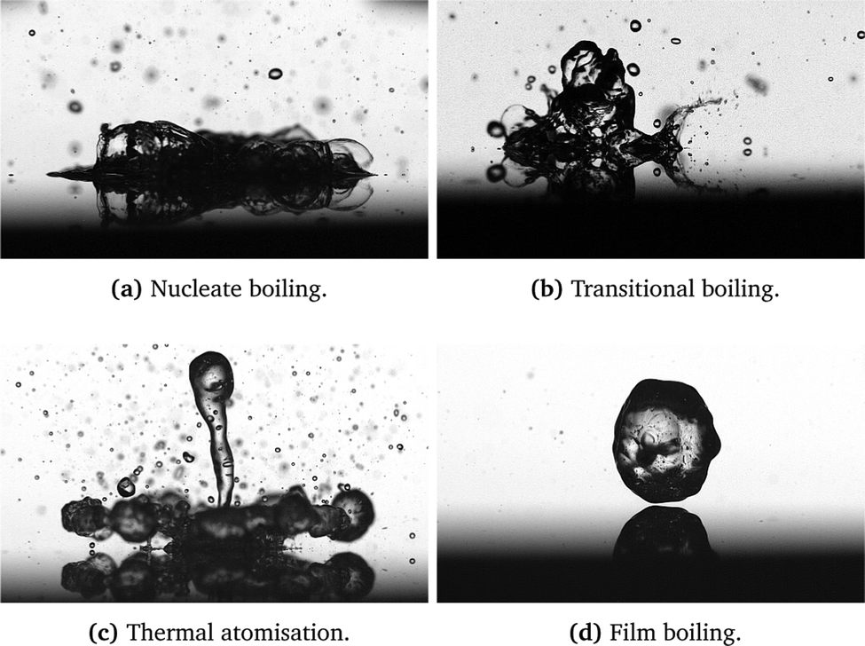 | ||
| Fig. 1 Typical regimes observed for an impact of a distilled water drop onto a hot substrate. The impact parameters are d0 = 2.3 mm, impact velocity U0 = 1 m s−1 at various initial wall temperatures, respectively – (a) 170 °C, (b) 240 °C, (c) 340 °C, and (d) 420 °C. | ||
• at higher temperatures, the relative area covered by the bubbles increases and, under certain conditions, leads to the percolation of vapor channels17,18 in the transition boiling regime (Fig. 1b);
• at even higher temperatures boiling occurs at the interface of a thin vapor layer within the film boiling regime, leading to drop rebound, as shown in Fig. 1(d);5,19–22
• at high impact velocities a strong liquid overheating leads to the liquid film breakup by the vapor flow in the thermal atomization regime, shown exemplary in Fig. 1(c).23–25
The influence of additional components such as lubricants and/or other additives on the drop impact outcome, heat flux regimes and residence time still remains largely unknown, although some work is available on drop impact of a variety of compound drops26 as well as about the impact on lubricated and coated surfaces.27,28 Splashing of binary drops, such as particle dispersions29, as well as numerous effects which occur during the heat transfer between the heated substrate and impacting drop21,30 were studied intensively for different experimental system configurations.
In some cases, the presence of an additional phase in a liquid drop can lead to a significant change in the drop outcome. For example,31,32 the presence of small impurities or gasification of the liquid can lead to micro explosions in the drop during its spreading on a hot substrate. However, the mechanisms of boiling in a suspension drop are completely different. This matter will be discussed in detail in this manuscript.
It is important to determine possible mechanisms and factors influencing the thermodynamic and hydrodynamic phenomena accompanying the impact of a suspension drop onto a heated substrate. Among these factors are:
• change of the effective thermodynamic and mechanical properties of the liquid;
• the formation of a deposited layer of solid particles;
• accumulation of particles at the surface of the expanding bubble;
• dynamic effects of particles influencing bubble stability, accumulation in thin films and their breakup.
These phenomena are shown schematically in Fig. 2. The effects of the effective thermal and material properties of the liquids do not explicitly lead to new physical phenomena. Nevertheless, the addition of particles leads to a significant change of the liquid viscosity, surface tension, thermal diffusivity and conductivity as well as other relevant thermal properties. The liquid properties have to be measured for different concentrations of the solid phase. In the present case, the addition of lubricants does not significantly change these properties.
 | ||
| Fig. 2 Assumed phenomena associated with the particulate phase in a suspension drop on a hot substrate, which potentially influence the thermodynamic and hydrodynamic phenomena in the drop. | ||
A deposited solid layer is formed at the wetted part of the substrate due to the local liquid evaporation, which leads to the accretion of the particulate phase from the suspension. At wall temperatures not exceeding the limit for the drop boiling, whilst the drop slowly evaporates, the deposition occurs mainly near the receding contact line, leading to the formation of coffee stain patterns.33–35 At higher temperatures, corresponding to the nucleate boiling regime, the contact lines are formed by each of the multiple vapor bubbles. The particles are deposited randomly on the substrate. The deposited layer can potentially influence the heat transfer, as analyzed in Section 3.2.
Moreover, particles can also accumulate at the surfaces of the expanding vapor bubbles. The process of particle accumulation can be influenced by particle diffusion and by the propagation of the bubble interface in the liquid region due to evaporation. Two main values characterize the dynamics of the particles in suspension. One is the Stokes number, defined as
 | (1) |
The next dimensionless number characterizing the importance of particle diffusion is the Péclet number
 | (2) |
Correspondingly, in the cases Stk ≪ 1 and Pe ≫ 1, particle accumulation leads to the creation of a crust. Such crusts are often observed after drying a suspension drop.38–41
When the bubble height is comparable with the drop height, the particles are collected in a thin liquid film, which becomes thinner as the bubble continues to expand. The breakup of these films leads to a splash, characterized by the generation of small secondary drops, which are visible in Fig. 1(a) and (b), or in Fig. 4(i)–(l). The presence of the particles can significantly influence the dynamics of the thin liquid films, especially if the film thickness is similar to the particle size. In many cases, the presence of the particles initiates an early film breakup, which leads to larger drops but to a less intense splash, as shown in Fig. 4(e)–(h) or Fig. 4(a)–(d). These well-known phenomena govern the principle of anti-foam properties of some suspensions.42–44
The main objective of the present experimental study is the examination of the influence of graphite based industrial lubricants on the drop residence time and drop impact regimes during the interaction between graphite-water drops with a heated substrate. The scope of the experimental research also encompasses the impact of a deposited layer of graphite particles on drop boiling. Special attention was given to the nucleate boiling regime, where comparisons were drawn with an existing residence time model for pure water. The experiments were performed for different volume concentrations of lubricants and surface temperatures, thus covering all the above-mentioned outcome regimes. Finally, we show that the residence time of the lubricant containing drop is proportional to the corresponding time of the pure liquid, which indicates that generally the dynamics of drop impact is very similar. However, the residence time monotonically increases with the lubricant concentration. This effect can be explained by the influence of the dispersed phase on the effective thermal properties of the liquids and by the formation of a deposited layer of the solid particles of the lubricant, which influences the magnitude of heat transfer.
2 Experimental methods
2.1 Configuration of experimental setup
The experimental setup is designed to observe and characterize the impact of a single drop onto a heated surface. A schematic representation of the setup is shown in Fig. 3(a), comprising a heating system with a temperature controller (2) and a replaceable impact surface (1); the drop generation system (3); an observation system (4) with a high-speed camera with LED illumination and diffuser plate; and a computer unit (5) for data acquisition and control of the experimental flow. | ||
| Fig. 3 Schematic representation of experimental facility. | ||
The heating system consists of a replaceable impact target and a heated aluminum cylinder. The impact target is a stainless steel (type 1.4841) cylinder with a diameter of 50.8 mm and height of 20 mm. The impact surface of the target is mirror polished, with an average roughness of 0.05 μm. The impact target is embedded in a heated coaxial aluminum cylinder, equipped with a 315 W cartridge heater (hotset hotrod HHP) to achieve the desired temperature of the impact surface. Additionally, ceramic insulation material (C610) is used to insulate the side walls.
The temperature of the stainless steel impact surface is controlled by a PID thermo-controller (HOTSET c448), together with a type-J thermocouple placed 0.5 mm below the upper surface. A more detailed sectional view of the heating system can be seen in Fig. 3(b). Given the high thermal conductivity of the target material, the temperature difference between the thermocouple and the impact surface can be neglected and the surface temperature can be approximated to be equal to the measured substrate temperature provided by the thermocouple.
Drops are generated with a syringe pump (World Precision Instruments) and a blunt hypodermic needle (Braun Sterican). The desired diameter of the drop can be selected by the displacement of the syringe. The position of the needle can be changed above the impact surface using a linear motor, thus achieving different impact velocities of the falling drops.
A CMOS high-speed camera (Vision Research Phantom V12.1), with a maximum resolution of 1280 × 800 pixels at 6242 fps, is used to record side-view images and videos of the drop impact. An image based auto trigger engages when the droplet arrives in the proximity of the target. The high-speed camera is additionally equipped with a 60 mm macro lens (Nikon AF NIKKOR 1:2.8 D) and spacer rings (Nikon PK).
An LED spotlight (Veritas miniConstellation 120C28) with a power of 120 W is used for illumination. The illumination is placed behind the drop (and directed co-linear with the high-speed camera) resulting in shadowgraphy imaging. A diffuser plate with a diffusion angle of 30° is placed between the LED illumination and the impact zone of the drop in order to achieve more uniform illumination of the falling drop.
2.2 Preparation and properties of the suspensions
As a base for the preparation of the suspensions, the industrial lubricant LUBRODAL F10545 is used, which is produced by the company Fuchs LUBRITECH. The lubricant LUBRODAL F10545 can be described as a water-miscible graphite dispersion, supplied as a concentrate. In the industry, it is mostly used for cooling and lubrication during hot-die forging as well as in various forming operations. The solid particles of layered graphite in suspension range in size from 5 to 20 μm. In order to stabilize the suspension and aid the spreading and formation of the adherent lubricant films on the die surface, organic and inorganic components (surfactants and binders) are present in the lubricant concentrate as well. The exact components present in the concentrate are: silicic acid sodium salt 1.00% – <5.00%, morpholin derivative 0.10% – <0.60%, and pyrithione, sodium salt 0.001% – <1.00%; all concentrations are given in percent by weight. Prior to the experiment, and following the dilution of lubricant with water, the concentration of the additional components decreases further, leaving solid graphite particles as a dominant influencing factor.Suspensions of different volume concentrations are prepared by mixing the concentrate with distilled water. In this study, the volumetric concentrations of the suspensions range from φ = 1.43% to φ = 4.3%. In most industrial applications, the maximum solid particle concentration of φ = 4.3% is defined as the upper limit. The lower limit φ = 1.43% in this study corresponds to the smallest ratio of the solid particles at which some effects of the particles on the drop impact dynamics have been identified.
Since the concentration of the solid particles is small, it is expected that most of the thermal properties are similar to that of water. The boiling temperature of the mixture is Tsat= 100 °C. The viscosity of a dilute suspension can be estimated using the approximation,47 which generalizes the well known Einstein formula48
 | (3) |
This estimation yields a maximum increase of the effective viscosity of 12% for the suspensions with the highest concentrations. The effect of the solid particles on the viscosity of the suspension can also be represented in terms of the Ohnesorge number:
 | (4) |
The surface tension of the different suspensions has been measured at room temperature. It depends slightly on the suspension concentration. The surface tension of the suspensions is σ = 71.19 mN m−1 for φ = 1.43%, σ = 70.48 mN m−1 for φ = 2.57% and σ = 68.88 mN m−1 for φ = 4.3%.
3 Suspension drop impact onto a hot substrate: nucleate boiling regime
3.1 Observations of impact: diminution of splash by solid particles
The observed hydrodynamic regimes of suspension drop impact onto a hot substrate are qualitatively similar to the regimes of drop impact of pure, one component liquids, shown exemplary in Fig. 1, with some slightly different effects attributed to the suspension drop impact. It should be noted that a solid layer of particles is deposited after each drop impact. Therefore, in order to investigate a suspension drop impact onto a clean substrate, the deposited layer was removed before each single drop impact experiment, thus achieving good repeatability of experiments. Removal of the deposited layer was achieved using the following steps. First, the surface was cleaned with distilled water. Afterward, it was polished with a mirror polishing paste, reaching an average roughness of 0.05 μm for the impact surface. Subsequently, the target was cleaned with isopropanol alcohol to remove polish residuals.In Fig. 4 examples of a drop impact of distilled water as well as suspensions of φ = 1.43% and φ = 4.3% onto a substrate with Tw0 = 150 °C are shown. In all three cases, the impact is governed by nucleate boiling. However, the phenomenon is significantly different in each case. Drop impact of distilled water is accompanied by an intensive generation of fine secondary drops, appearing after 81 ms (see Fig. 4b), and several bubbles of the sizes exceeding the height of the drop. Addition of a very small amount of solid particles leads to a significant time delay of splash inception. For the suspension of φ = 1.43%, shown in Fig. 4(g), the splash has been observed after 300 ms and the size of the secondary drops is much larger in comparison with distilled water. For higher suspension concentration, φ = 4.3%, the splash is almost completely suppressed. Only a few relatively large secondary drops have been observed in Fig. 4(i)–(l).
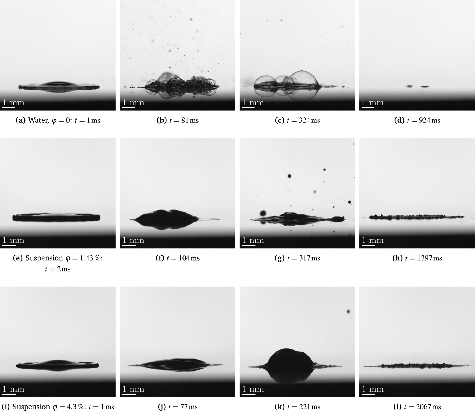 | ||
| Fig. 4 Drop impact in the nucleate boiling regime. Effect of the suspension concentration, φ = 0 (distilled water) (a–d), φ = 1.43% (e–h) and φ = 4.3% (i–l) on the drop splash and evaporation. The initial substrate temperature Tw0 = 150 °C, drop diameter d0 = 2.3 mm and impact velocity U0 = 1.7 m s−1 are the same for all the cases. The corresponding videos are available on Zenodo.46 | ||
In order to better understand the main mechanisms that lead to splashing, the boiling of the distilled water drop shown in Fig. 5 is compared with the observations of the boiling in the suspension drop in Fig. 6. Splashing of a liquid drop during the nucleate boiling regime occurs due to the breakup of the thin film domes formed by an expanding vapor bubble when the bubble size is much larger than the thickness of the liquid layer at the substrate. The breakup process of the dome,49,50 shown in Fig. 5, includes the dome growth and spontaneous perforation by a hole, (Fig. 5b). The Taylor rim,51 which propagates toward the liquid film, surrounds this hole. The rapid hole expansion is caused by rim propagation. Moreover, the rim itself is unsteady, as can be seen in Fig. 5(c). The rim instability leads to the formation of many finger-like jets, which break up into a number of fine secondary drops of the size comparable with the film thickness of the dome.
 | ||
| Fig. 5 Impact and splash of a distilled water drop in the nucleate boiling regime. A typical behavior of a single dome formed from a growing vapor bubble. Its expansion (a), spontaneous hole formation (b), bounded by an unstable rim (c), breakup and collapse (d). The impact parameters correspond to the case shown in Fig. 4(a)–(d). | ||
 | ||
| Fig. 6 Impact and splash of a suspension drop in the nucleate boiling regime, φ = 1.43%. A typical behavior of a single dome leading to the pinch-off of the secondary drops: dome formation and growth (a), unstable dome receding, leading to the formation of a finger-like jet (b), jet propagation and emergence of the jet instabilities (c), leading to the pinch-off of the secondary drops (d). The impact parameters correspond to the case shown in Fig. 4(e)–(h). | ||
A typical behavior of a single dome during nucleate boiling of a suspension drop is shown in Fig. 6. The dome grows due to the evaporation of the water from the suspension. The concentration of the particles thus also grows, leading to a significant increase of the viscosity of the liquid film forming the dome. At some instant, the dome starts to recede. This stage is unstable and leads to the emergence of a jet. Finally, the dome collapses while several secondary drops appear after the jet breakup. In the case of suspensions, the diameter of largest secondary drops observed is about 200 μm, whereas in the case of distilled water, the diameter of largest secondary drops observed is around 100 μm.
3.2 Nucleate boiling regime: particles deposition and heat transfer
 | (5) |
 | ||
| Fig. 7 Main phenomena accompanying the impact of a liquid drop onto a hot substrate in the nucleate boiling regime. | ||
The inviscid solution is valid only for the stage when the lamella is much thicker than the thickness of the viscous boundary layer formed at the substrate immediately after impact. The exact similarity solutions of the Navier–Stokes equations for viscous flow in the spreading drop are obtained for axisymmetric drop spreading,55 as well as for a three-dimensional case associated with the oblique drop impact.56 The evolution of a uniform thickness of the viscous boundary layer is predicted in the form  . The predictions55 for the flow in the viscous boundary layer over the duration of the spreading phase and for the residual lamella thickness agree well with direct numerical simulations and with the experimental data.54,57
If the initial temperatures of the drop and the substrate differ, the heat transfer is governed by heat conduction in a thin thermal boundary layer in the substrate and by convection and conduction in a thermal boundary layer in the spreading lamella. The exact similarity solution56 for this heat transfer problem satisfies the condition of the continuity of the temperature and of the heat flux at the substrate interface. The predicted thicknesses of the thermal boundary layers in the drop and in the substrate are respectively  and
and  , where α denotes the thermal diffusivity of the corresponding material. The thickness of the thermal boundary layer is much smaller than the spreading diameter of the drop. The ratio of the total heat flux in the substrate in the radial direction and the heat flux at the wetted interface in the axial direction is of the same order as the ratio of the corresponding areas, ∼hαs/Dspreading ≪ 1.
In our experiments, the spreading diameter is approximately Dspreading ≈ 5 mm. The thermal diffusivity of metals is αs ∼ 10−5 m2 s−1. The thickness of the thermal boundary layer 1 second after impact is therefore hαs ∼ 3 mm. Therefore, for all cases when the drop residence time is smaller than 1 second, the heat transfer is dominated by heat conduction in a thin thermal boundary layer, since for them ∼hαs/Dspreading ≪ 1. Most of the experiments in this study satisfy this condition.
The theoretical predictions based on the similarity solution for the heat flux56 agree very well with direct numerical computations of heat transfer in a spreading drop.58–60
This result is very important for the current study, which indicates that the heat transfer problem in the substrate and in the liquid drop can be solved using a simplified one-dimensional approach. Moreover, a similar one-dimensional approach is used to treat theoretically the problems influenced by phase change, for example to predict the thickness of a ice layer61 after impact of a supercooled drop onto an ice substrate, or to estimate the heat transfer associated with drop or spray impact onto a hot substrate in the nucleate boiling and film boiling regimes.6,7,14
At some instant, when the time after impact exceeds the bubble waiting time,62 numerous vapor bubbles appear at the wetted substrate interface. This phenomenon is shown schematically in Fig. 7(c). The temperature at the interface of an evaporating bubble is equal to the saturation temperature of the liquid. It is shown that the temperature of the liquid solid interface also quickly approaches the saturation point.6,7 This condition determines the thermal boundary conditions for the heat transfer problem in the substrate and significantly simplifies the problem modeling.
Formation and growth of vapor bubbles, observed during nucleate boiling regime, indicates that the surrounding liquid in the vicinity of the substrate is slightly superheated. Each bubble evaporates at its interface, where the temperature is close to the saturation temperature. Liquid evaporation at the bubble surface leads to the continuous reduction of the liquid content in the suspension, and correspondingly to the increase of the concentration of the solid phase. Therefore, the viscosity of the suspension increases due to the liquid phase evaporation. This viscosity rise is the main reason for the reduction of the rate of splashing for suspension drops in comparison with the splash of pure one-component liquid drops.
The second phenomenon is associated with the nucleation of a vapor bubble and its fast expansion leading to the dewetting motion of the contact line, formed at the substrate by each bubble. The particle deposition in the vicinity of the moving contact line is known as coffee-ring effect.33,63,64 The evaporation of multiple vapor bubbles at the substrate thus leads to the formation of a porous solid particulate layer, as shown schematically in Fig. 7(e).
It is important to clarify whether the scaling for the drop residence time, required for its complete evaporation at the substrate, developed for pure liquids,7 is still applicable for the modeling of heat transfer and evaporation of multiphase drops.
In the next section, a one-dimensional model for heat transfer in the substrate and for the particle deposition is developed, which is based on the above-mentioned simplified theoretical approach.
 | ||
| Fig. 8 Heat transfer in a substrate, liquid drop and in a deposited layer of the particles from the suspension. | ||
In order to evaluate the influence of the deposited particles on the heat transfer during drop evaporation and on the scale for the characteristic residence time of this drop in the nucleate boiling regime, a one-dimensional model is developed in this study. The model is valid only in the cases when the thickness of the deposited layer hp and the thickness of the thermal boundary layer in the substrate are both much smaller than the spreading diameter of the drop.
The ratio of the thickness of thermal boundary layer to the spreading diameter and its relevance to the validity of the simplified one-dimensional approach to the thermal problem have been discussed in Section 3.2.1.
The smallness of the thickness of the deposited layer in comparison with the drop spreading diameter is evident for the suspensions considered in this study. This is ensured by the small values of the volumetric concentrations of the particulate phase φ ≪ 1. The measured residual thickness of the deposited layer is ∼10−4 m, as shown in Fig. 9, while the spreading diameter is ∼10−2 m. Moreover, the average thickness of the deposited layer in Fig. 9 is almost uniform, it almost does not depend on the radial coordinate, except in close vicinity to the spot edge. This result supports the simplified assumption of the mainly one-dimensional heat transfer at the substrate.
 | ||
| Fig. 9 Confocal microscope images of the deposited layer after suspension drop (φ = 4.3%) impact onto a hot substrate. The parameters of impact correspond to the case shown in Fig. 4(i)–(l). | ||
The one-dimensional heat equation in each solid region is given as
 | (6) |
The heat equation has to be solved using the boundary conditions
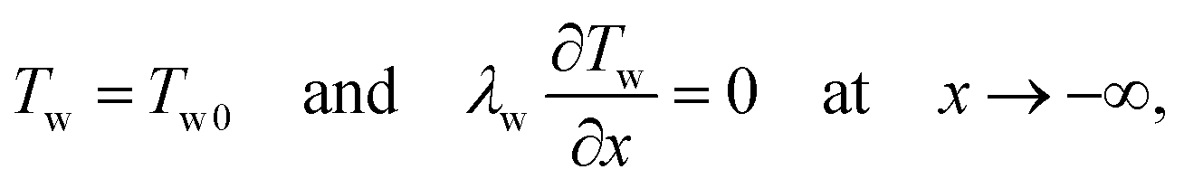 | (7) |
 | (8) |
| Tp = Tpi at x = hp(t), | (9) |
The surface of the deposited layer experiences nucleation and expansion of the vapor bubbles, as shown schematically in the sketch in Fig. 8. It has been shown already in the analysis of the nucleate boiling of pure liquids7 that the temperature Tpi of the wetted interface of the solid deposited layer lies rather close to the saturation temperature Tsat
| Tpi ≈ Tsat. | (10) |
Next, the deposition rate of the particles is governed by the evaporation rate of the liquid ṁev
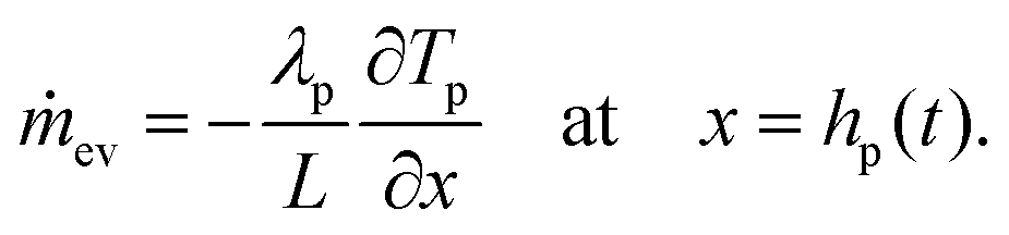 | (11) |
 | (12) |
The similarity solution of system of equations (6) is found in the form
 | (13) |
 | (14) |
 | (15) |
 | (16) |
The dimensionless thickness of the deposited layer H is the root of a transcendental equation
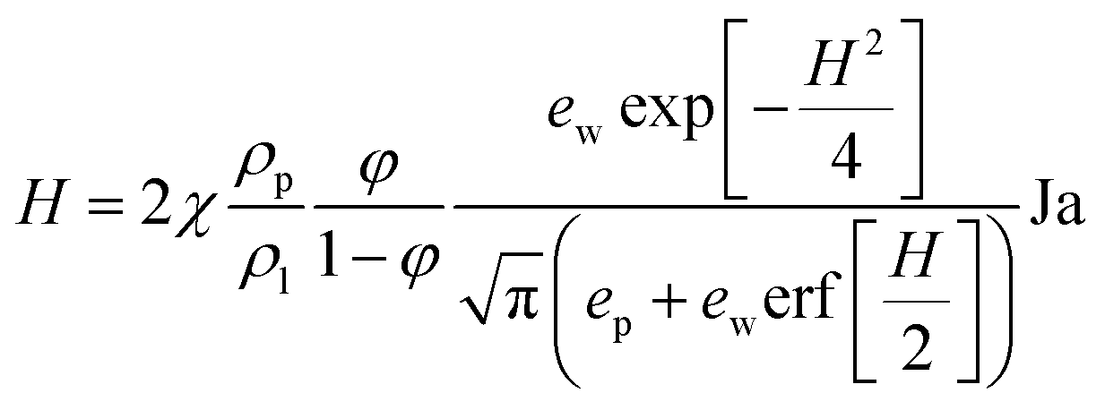 | (17) |
 | (18) |
The heat flux ![[q with combining dot above]](https://www.rsc.org/images/entities/i_char_0071_0307.gif) p at the interface of the deposited particle layer is expressed as
p at the interface of the deposited particle layer is expressed as
 | (19) |
 | (20) |
A topographical layer and a 3D image of a deposited solid layer obtained after the impact of a suspension drop and its evaporation in the nucleate boiling regime is shown in Fig. 9. The deposited layer is a highly porous medium of varying height. The circular particle free dark regions in the upper graph in Fig. 9 most probably correspond to the positions of the bubbles. The measured relative area of the particle free surface is ε0 = 0.42.
The measured apparent area-averaged layer thickness is hexp = 50.80 μm. This thickness is significantly larger than the theoretically predicted volume averaged thickness hp of the layer. The difference is explained by the porosity of the layer. This porosity can be roughly approximated by the φspheres ≈ 0.4 of randomly close packing of hard spheres.67–69 The theoretically predicted average thickness of the porous deposited layer is therefore hp/(1 − φspheres) ≈ 42.0 μm. This value is of the same order as the measured value hexp.
An attentive reader may wonder why the apparent layer shown in Fig. 9 looks much thicker. This impression is caused by the presence of ∼200 μm high coffee-rings around the particle free holes produced by the vapor bubbles.
3.3 Residence time of a suspension drop
The expression (19) forp can be linearized using the value of the dimensionless thickness of the deposited layer H as a small parameter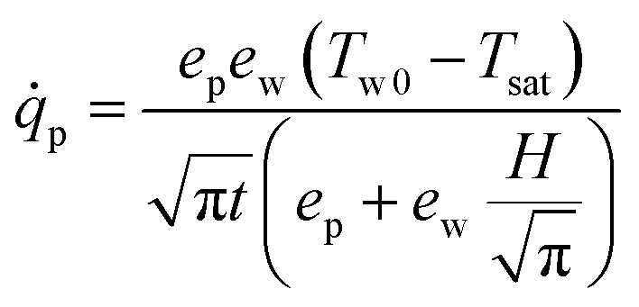 | (21) |
| ΔTw = Tw0 − Tsat | (22) |
 | (23) |
 | (24) |
In this study a simplified form of this equation will be used for convenience
 | (25) |
In order to characterize the influence of the dispersed solid phase on the suspension drop impact, the residence time is measured. Results for the range of the wall overheat temperatures are presented in Fig. 10 in comparison with the measurements of the residence time for distilled water drops. Values of corresponding Reynolds numbers for obtained data vary from 2814–3059 where Re = 2814 corresponds to the largest suspension concentration φ = 4.3%, while Re = 3059 corresponds to the distilled water case. The range of Weber numbers is, accordingly, We = 60–56.
 | ||
| Fig. 10 The residence time of the impacting drop as a function of the substrate overheat temperature for various suspension concentrations in comparison with the theoretical predictions (25). Drop diameter d0 = 2.3 mm and impact velocity U0 = 1.33 m s−1 are the same for all the cases. | ||
Nucleate boiling has been observed in the range of the wall temperatures, corresponding to ΔTw = Tw0 − Tsat from 50 °C to 100 °C. The data for water and for suspensions follow the predicted values from eqn (25) scaling tr ∼ ΔTw−2. Moreover, the validity of the expression for the residence time (25) has been examined by the measurement of the residence time of a distilled water drop onto a solid deposited layer formed by a suspension drop impact on the nucleate boiling regime. Such deposited layers formed at the substrate after impact can be seen in Fig. 4(h) and (l). The difference of the measured residence time of a distilled water drop impacting onto a clean substrate and onto a deposited layer is only minor. This result supports the estimation of the negligibly small contribution of the effect of the deposited particles on heat transfer in the nucleate boiling regime.
As shown in Fig. 10, the values of the residence times of suspension drops increase for higher suspension concentrations at smaller wall overheats up to 170 °C. On the other hand, the time decrease of the residence time for the suspensions of lower concentrations or pure distilled water can be attributed to the higher mass of the secondary drops. For higher suspension concentrations, φ = 2.57% and φ = 4.3% the residence time change is only minor. This means that the mass of the secondary drops is negligibly small in comparison to the initial drop mass. Therefore, the heat from the wall goes completely toward the drop evaporation and is not influenced by splash.
The variation of the residence time in the expression (25) can be implemented through adjustment of the dimensionless parameter kw. The dependence of kw on the volume concentration of the solid particles in the suspension is shown in Fig. 11. For smaller values of φ the constant kw approaches the value kw = 1.9, determined for water. For larger suspension concentrations, the value of the constant approaches the limiting nearly constant value kw ≈ 1.5, corresponding to the case when the splash is completely suppressed.
 | ||
| Fig. 11 Dependence of the dimensionless empirical constant kw, defined in eqn (25), on the solid phase volume concentration φ in the suspension. The error bars represent one standard deviation. | ||
4 Higher wall temperatures: film boiling and thermal atomization
In the range of wall overheat ΔTw = 100–170 °C, experimental data for residence time, shown in Fig. 10, deviate noticeably from the theoretical model for the nucleate boiling. This deviation is attributed to the apparent drop foaming and reduction of the wetted contact area with the substrate, associated with the transition boiling regime. In this regime, the residence time of the mixture drops is much longer in comparison with pure water drops.Above the wall temperature corresponding to ΔTw ≈ 170 °C, a termination of the transition boiling regime occurs, and all curves fall to a lower plateau, approximately at the wall overheat ΔTw ≈ 200 °C. Several examples of a drop impact onto a solid substrate initially heated to the temperature Tw = 420 °C are shown in Fig. 12 for various suspension concentrations. At this temperature, the drop impact of distilled water leads to a total drop rebound, caused by the film boiling phenomenon. This case is shown in Fig. 12(a)–(d). Interestingly, even very small concentrations of suspension particles cause a completely different drop behavior.
 | ||
| Fig. 12 Drop impact onto a hot substrate initially heated to the temperature Tw0 = 420 °C. Effect of the suspension concentration, φ = 0 (distilled water) (a–d), φ = 1.43% (e–h) and φ = 4.3% (i–l) on the regime of drop impact. The initial drop diameter d0 = 2.3 mm and impact velocity U0 = 1.7 m s−1 are the same for all the cases. The corresponding videos are available on Zenodo.46 | ||
4.1 Mechanisms of thermal rebound of a one-component liquid drop
Before starting a discussion on the different behavior of suspension drops, let us describe the mechanisms of rebound of pure liquid. The accompanied phenomena, often wrongly associated with the film boiling regime, are described in detail in the recent experimental and theoretical study.17 This regime includes some phenomena typical to the nucleate boiling regime and to the film boiling regime. It is characterized by the drop rebound.The duration of the drop spreading is determined by the time required for the expansion of the viscous boundary layer to the thickness of the radially spreading lamella.55 In the nucleate boiling regime, the spreading is influenced by the generation of multiple vapor bubbles. It is obvious that the intensity of evaporation increases with the initial substrate temperature. If the nucleation sites are distributed at the substrate and in time randomly, there is a probability of their coalescence. Under some conditions, at the percolation threshold, the bubble clusters form continuous vapor channels. This changes the character of the flow.
Comparison of the drop spreading time and the time required for bubble percolation, leading to the formation of the vapor channels at the substrate surface, allows to estimate the temperature at which the drop rebounds from the substrate after its spreading and receding.17 The estimated temperatures for the drop rebound
 | (26) |
It is important to note that the temperature Trebound is much smaller than the temperature associated with the inception of the film boiling regime. The rebound occurs despite the drop contact with the substrate.
4.2 Rebound suppression by a particulate phase
The contact of a suspension drop with a hot substrate initiates a very strong local heat flux, violent evaporation and formation of the vapor flow, accelerating the particles. This flow leads to the ejection of the multiple jets emerging at the early stages of drop impact, seen in Fig. 12(f) or (j). This is highly analogous to thermal atomization of one-component liquid drops,23 when the impact velocity is so high that it ensures the contact of the liquid and the substrate even at very high temperatures, and where such jetting phenomenon has not been observed. The jets appear only for suspension drops.Moreover, further suspension drop behavior on the hot substrate is very similar to the thermal atomization regime of a one-component liquid.23 This regime is characterized by the generation of a dense uprising flow of fine secondary drops and the drop levitation before receding. This phenomenon is associated with the contact of the liquid and very hot substrate, promoted by the high impact velocity of the drop. However, in the case of suspension drops, the drop rebound is prevented even at relatively low impact velocities.
This behavior can be explained by several factors. First is the pinning of the vapor bubbles due to the coffee rings, shown in Fig. 9. These rings ensure the constant position for the bubble nucleation, since the corresponding spots are particle free. Therefore, the deposited layer prevents bubble coalescence and their percolation, which would allow drop rebound. The mechanism is analogous to the inverse Leidenfrost effect achieved by coating the solid substrate with a porous nano-fiber mat.30
To examine this hypothesis, experiments have been performed using a distilled drop impact onto a heated substrate coated by a porous layer of solid particles, deposited by a preliminary impact of a suspension drop. The presence of the deposited layer on the substrate indeed cause the jetting and thermal atomization at Tw = 420 °C while the impact onto a clean substrate leads to complete drop rebound.
The second reason for the suppression of the drop rebound is the significant increase of the liquid viscosity due to the evaporation of the bulk liquid of the drop. Correspondingly, the critical temperature for the drop rebound increases, as predicted by eqn (26).
5 Conclusions
The impact of a suspension drop onto a heated substrate, leading to the drop boiling in different thermodynamic and hydrodynamic regimes, has been studied. The maximum temperature of the substrate was 420 °C. The presence of solid particles in the liquid suspension does not lead to a significant change of the effective material properties. Nevertheless, the particles in suspension significantly affect the impact outcome.A diminution and almost complete suppression of the drop splash in the nucleate boiling regime has been observed, caused probably by particle deposition at the interfaces of the expanding bubbles. The reduced mass loss due to splash leads to a slight increase of the residence time of the suspension drops. The residence time in the nucleate boiling regime is proportional to ΔTw−2, predicted by the self-similar theoretical solution of the heat transfer and particle deposition phenomenon.
Furthermore, the presence of the particles leads to suppression of the drop rebound and film boiling regime. Instead, a thermal atomization regime is observed, even for suspensions with relatively small concentrations of the dispersed particulate phase, such as φ = 1.43% or even less. This effect is caused by drop contact line pinning by the deposited layer of the solid particles from the suspension. The deposited layer prevents also the percolation of the bubbles and thus suppresses the drop thermal rebound, even at relatively high substrate temperatures at which a one-component drop exhibits full rebound.
The results of this study will be useful for the modeling of the formation of the lubricating layer of deposited particles by cooling sprays, required for predictions of the evolution of its thickness and uniformity. Moreover, a significant influence is expected on the values of the Leidenfrost points of spray cooling if low concentration suspensions are used as cooling liquid.
Author contributions
C. T. and I. V. R. conceived the project. M. G. J. performed the single drop experiments with suspensions. J. B. S. performed the single drop experiments with distilled water. J. H. and C. T. were responsible for the scientific coordination of the project. I. V. R. developed theoretical description of the problem. All authors performed the data analysis and participated in writing the manuscript.Conflicts of interest
There are no conflicts to declare.Acknowledgements
The authors gratefully acknowledge financial support from the Deutsche Forschungsgemeinschaft (DFG) in the framework of SFB-TRR 75 (TP T02, project number 84292822).Notes and references
- S.-J. Chen and A. A. Tseng, Int. J. Heat Fluid Flow, 1992, 13, 358–369 CrossRef CAS.
- W.-L. Cheng, W.-W. Zhang, H. Chen and L. Hu, Renewable Sustainable Energy Rev., 2016, 55, 614–628 CrossRef CAS.
- A. Lefebvre and V. Mcdonell, Atomization and Sprays, CRC press, 2nd edn, 2017 Search PubMed.
- G. Liang and I. Mudawar, Int. J. Heat Mass Transfer, 2017, 115, 1174–1205 CrossRef CAS.
- G. Liang and I. Mudawar, Int. J. Heat Mass Transfer, 2017, 115, 1206–1222 CrossRef CAS.
- F. Tenzer, I. V. Roisman and C. Tropea, J. Fluid Mech., 2019, 881, 84–103 CrossRef CAS.
- J. Breitenbach, I. V. Roisman and C. Tropea, Phys. Rev. Fluids, 2017, 2, 074301 CrossRef.
- J. Breitenbach, I. V. Roisman and C. Tropea, Exp. Fluids, 2018, 59, 1–21 CrossRef.
- A. L. Yarin, I. V. Roisman and C. Tropea, Collision phenomena in liquids and solids, Cambridge University Press, 2017 Search PubMed.
- A. L. Yarin, Annu. Rev. Fluid Mech., 2005, 38, 159–192 CrossRef.
- S. Batzdorf, S. Fischer, T. Gambaryan-Roisman and P. Stephan, Int. J. Heat Mass Transfer, 2013, 61, 605–614 CrossRef.
- R. Rioboo, M. Marengo and C. Tropea, Atomization Sprays, 2001, 11, 155–166 CAS.
- M. Marengo, C. Antonini, I. V. Roisman and C. Tropea, Curr. Opin. Colloid Interface Sci., 2011, 16, 292–302 CrossRef CAS.
- J. Breitenbach, I. V. Roisman and C. Tropea, Int. J. Heat Mass Transfer, 2017, 110, 34–42 CrossRef.
- I. V. Roisman, R. Rioboo and C. Tropea, Proc. R. Soc. London, Ser. A, 2002, 458, 1411–1430 CrossRef CAS.
- J. Bernardin, C. Stebbins and I. Mudawar, Int. J. Heat Mass Transfer, 1997, 40, 247–267 CrossRef.
- J. B. Schmidt, J. Hofmann, F. M. Tenzer, J. Breitenbach, C. Tropea and I. V. Roisman, Commun. Phys., 2021, 4, 1–8 CrossRef.
- P. Chantelot and D. Lohse, Phys. Rev. Lett., 2021, 127, 124502 CrossRef CAS PubMed.
- T. Tran, H. J. Staat, A. Prosperetti, C. Sun and D. Lohse, Phys. Rev. Lett., 2012, 108, 036101 CrossRef PubMed.
- J. Breitenbach, I. V. Roisman and C. Tropea, Int. J. Heat Mass Transfer, 2017, 110, 34–42 CrossRef.
- M. Piskunov, J. Breitenbach, J. Schmidt, P. Strizhak, C. Tropea and I. Roisman, Int. J. Heat Mass Transfer, 2021, 165, 120672 CrossRef CAS.
- G. Castanet, W. Chaze, O. Caballina, R. Collignon and F. Lemoine, Phys. Fluids, 2018, 30, 122109 CrossRef.
- I. V. Roisman, J. Breitenbach and C. Tropea, J. Fluid Mech., 2018, 842, 87–101 CrossRef CAS.
- P. Emerson, J. Crockett and D. Maynes, Int. J. Heat Mass Transfer, 2021, 164, 120559 CrossRef CAS.
- M. Chen, D. Chen, Y. Liu, H. Liu and H. Liu, Int. J. Heat Mass Transfer, 2022, 185, 122412 CrossRef CAS.
- N. Blanken, M. S. Saleem, M.-J. Thoraval and C. Antonini, Curr. Opin. Colloid Interface Sci., 2021, 51, 101389 CrossRef CAS.
- M. Y. Pack, H. W. Hu, D. I. Kim, Z. Zheng, H. A. Stone and Y. Sun, Soft Matter, 2017, 13(12), 2402–2409 RSC.
- E. Esmaili, Z.-Y. Chen, A. Pandey, S. Kim, S. Lee and S. Jung, Appl. Phys. Lett., 2021, 119, 174103 CrossRef CAS.
- M.-J. Thoraval, J. Schubert, S. Karpitschka, M. Chanana, F. Boyer, E. Sandoval-Naval, J. Dijksman, J. Snoeijer and D. Lohse, Soft Matter, 2021, 17(20), 5116–5121 RSC.
- C. M. Weickgenannt, Y. Zhang, S. Sinha-Ray, I. V. Roisman, T. Gambaryan-Roisman, C. Tropea and A. L. Yarin, Physical review. E, Statistical, nonlinear, and soft matter physics, 2011, 84(3 Pt 2), 036310 CrossRef PubMed.
- L. Sijia, V. Mathai, Y. Wang, B. Sobac, P. Colinet, D. Lohse and C. Sun, Sci. Adv., 2019, 5, eaav8081 CrossRef PubMed.
- S. Lyu, H. Tan, Y. Wakata, X. Yang, C. K. Law, D. Lohse and C. Sun, Proc. Natl. Acad. Sci. U. S. A., 2021, 118, e2016107118 CrossRef CAS PubMed.
- R. D. Deegan, O. Bakajin, T. F. Dupont, G. Huber, S. R. Nagel and T. A. Witten, Nature, 1997, 389, 827–829 CrossRef CAS.
- A. G. Marin, H. Gelderblom, D. Lohse and J. H. Snoeijer, Phys. Rev. Lett., 2011, 107, 085502 CrossRef PubMed.
- H. B. Eral, D. M. Augustine, M. H. Duits and F. Mugele, Soft Matter, 2011, 7, 4954–4958 RSC.
- A. Einstein, Z. Elektrochem. Angew. Phys. Chem., 1908, 14, 235–239 CrossRef.
- A. L. Kholodenko and J. F. Douglas, Phys. Rev. E: Stat. Phys., Plasmas, Fluids, Relat. Interdiscip. Top., 1995, 51, 1081 CrossRef CAS PubMed.
- S. Maenosono, C. Dushkin, S. Saita and Y. Yamaguchi, Langmuir, 1999, 15, 957–965 CrossRef CAS.
- A. Yarin, G. Brenn, O. Kastner and C. Tropea, Phys. Fluids, 2002, 14, 2289–2298 CrossRef CAS.
- M. Mezhericher, A. Levy and I. Borde, Drying Technol., 2010, 28, 278–293 CrossRef CAS.
- N. Fu, M. W. Woo and X. D. Chen, Drying Technol., 2012, 30, 1771–1785 CrossRef.
- G. C. Frye and J. C. Berg, J. Colloid Interface Sci., 1989, 127, 222–238 CrossRef CAS.
- R. Aveyard and J. H. Clint, Faraday Trans., 1995, 91, 2681 RSC.
- P. R. Garrett, The Science of Defoaming: Theory, Experiment and Applications, CRC Press, 2016 Search PubMed.
- F. Lubritech, Lubrodal F105, https://www.fuchs.com/lubritech/en/product/product/118075-lubrodal-f-105/, 2021.
- M. Gajevic Joksimovic, J. B. Schmidt, I. V. Roisman, C. Tropea and J. Hussong, Electronic Supplementary Information: Impact of a suspension drop onto a hot substrate: diminution of splash and prevention of film boiling, Zenodo, 2022 DOI:10.5281/zenodo.6948527.
- G. Batchelor and J. Green, J. Fluid Mech., 1972, 56, 401–427 CrossRef.
- A. Einstein, Ann. Phys., 1906, 19, 230–247 Search PubMed.
- H. Lhuissier and E. Villermaux, J. Fluid Mech., 2012, 696, 5–44 CrossRef CAS.
- L. Opfer, I. V. Roisman, J. Venzmer, M. Klostermann and C. Tropea, Phys. Rev. E: Stat., Nonlinear, Soft Matter Phys., 2014, 89, 013023 CrossRef CAS PubMed.
- G. I. Taylor, Proc. R. Soc. London, Ser. A, 1959, 253, 296–312 Search PubMed.
- A. L. Yarin and D. A. Weiss, J. Fluid Mech., 1995, 283, 141–173 CrossRef CAS.
- I. V. Roisman, E. Berberović and C. Tropea, Phys. Fluids, 2009, 21, 052103 CrossRef.
- S. Bakshi, I. V. Roisman and C. Tropea, Phys. Fluids, 2007, 19, 032102 CrossRef.
- I. V. Roisman, Phys. Fluids, 2009, 21, 052104 CrossRef.
- I. V. Roisman, J. Fluid Mech., 2010, 656, 189–204 CrossRef CAS.
- J. Eggers, M. A. Fontelos, C. Josserand and S. Zaleski, Phys. Fluids, 2010, 22, 062101 CrossRef.
- E. Berberović, I. V. Roisman, S. Jakirlić and C. Tropea, Int. J. Heat Fluid Flow, 2011, 32, 785–795 CrossRef.
- M. Schremb, S. Borchert, E. Berberovic, S. Jakirlic, I. V. Roisman and C. Tropea, Int. J. Heat Mass Transfer, 2017, 109, 971–980 CrossRef.
- S. Batzdorf, J. Breitenbach, C. Schlawitschek, I. V. Roisman, C. Tropea, P. Stephan and T. Gambaryan-Roisman, Int. J. Heat Mass Transfer, 2017, 113, 898–907 CrossRef CAS.
- M. Schremb, I. V. Roisman and C. Tropea, J. Fluid Mech., 2018, 835, 1087–1107 CrossRef.
- V. P. Carey, Liquid-vapor phase-change phenomena: an introduction to the thermophysics of vaporization and condensation processes in heat transfer equipment, CRC Press, 2020 Search PubMed.
- N. D. Denkov, O. D. Velev, P. Kralchevsky, I. Ivanov, H. Yoshimura and K. Nagayama, Nature, 1993, 361, 26 CrossRef.
- P. J. Yunker, T. Still, M. A. Lohr and A. Yodh, Nature, 2011, 476, 308–311 CrossRef CAS PubMed.
- I. Roisman, J. Fluid Mech., 2010, 656, 189–204 CrossRef CAS.
- T. Pavlov, L. Vlahovic, D. Staicu, R. Konings, M. Wenman, P. Van Uffelen and R. Grimes, Thermochim. Acta, 2017, 652, 39–52 CrossRef CAS.
- G. D. Scott and D. M. Kilgour, J. Phys. D: Appl. Phys., 1969, 2, 863 CrossRef.
- J. G. Berryman, Phys. Rev. A: At., Mol., Opt. Phys., 1983, 27, 1053 CrossRef CAS.
- D. Coelho, J.-F. Thovert and P. M. Adler, Phys. Rev. E: Stat. Phys., Plasmas, Fluids, Relat. Interdiscip. Top., 1997, 55, 1959 CrossRef CAS.
- M. Abu-Zaid, Heat Mass Transfer, 2004, 40, 737–741 CAS.
- I. Buchmüller, PhD thesis, Technische Universität Darmstadt, Darmstadt, Germany, 2014.
- M. Itaru and M. Kunihide, Int. J. Heat Mass Transfer, 1978, 21, 605–613 CrossRef.
- P. Tartarini, G. Lorenzini and M. Randi, Heat Mass Transfer, 1999, 34, 437–447 CrossRef CAS.
| This journal is © The Royal Society of Chemistry 2023 |