
Packing and emergence of the ordering of rods in a spherical monolayer†
Dharanish
Rajendra
 a,
Jaydeep
Mandal
a,
Yashodhan
Hatwalne
b and
Prabal K.
Maiti
*a
a,
Jaydeep
Mandal
a,
Yashodhan
Hatwalne
b and
Prabal K.
Maiti
*a
aCentre for Condensed Matter Theory, Department of Physics, Indian Institute of Science, Bengaluru 560012, India. E-mail: maiti@iisc.ac.in
bRaman Research Institute, Bengaluru 560080, India
First published on 7th December 2022
Abstract
Spatially ordered systems confined to surfaces such as spheres exhibit interesting topological structures because of curvature induced frustration in orientational and translational order. The study of these structures is important for investigating the interplay between the geometry, topology, and elasticity, and for their potential applications in materials science, such as engineering directionally binding particles. In this work, we numerically simulate a spherical monolayer of soft repulsive spherocylinders (SRSs) and study the packing of rods and their ordering transition as a function of the packing fraction. In the model that we study, the centers of mass of the spherocylinders (situated at their geometric centers) are constrained to move on a spherical surface. The spherocylinders are free to rotate about any axis that passes through their respective centers of mass. We show that, up to moderate packing fractions, a two dimensional liquid crystalline phase is formed whose orientational ordering increases continuously with increasing density. This monolayer of orientationally ordered SRS particles at medium densities resembles a hedgehog—long axes of the SRS particles are aligned along the local normal to the sphere. At higher packing fractions, the system undergoes a transition to the solid phase, which is riddled with topological point defects (disclinations) and grain boundaries that divide the whole surface into several domains.
1 Introduction
The statistical mechanics of rod-like particles has been an important problem ever since Onsager developed the theory for (three dimensional) isotropic–nematic liquid crystalline (IN) phase transition in a system of hard rods.1 Since then, a number of studies have investigated the different phases and phase transitions for hard and soft rods.2–10 Bolhuis and Frenkel2 have extensively studied the phases of hard rods in bulk and showed that the phases and phase boundaries vary depending on the shape anisotropy A = L/D (D and L are the diameter and core length of the rod, respectively). Cuetos and Martinez-Haya3 have studied the effect of temperature on the phase diagram by using the mapping equation between soft and hard rods and observed triple points between different phases. Bates and Frenkel4 have simulated hard rods on a 2D plane, and showed that for A ≥ 6, there is a nematic phase with algebraically decaying orientational correlation, whereas, for small shape anisotropies, there is an isotropic phase with strong local positional and orientational correlation. External fields can also introduce novel phases in systems of soft polarizable spherocylinders.11 Furthermore, Dussi et al.12 have simulated different single component systems with particles of different shapes, and showed that depending on the system size, a prolate columnar phase appears in the system. But this columnar phase is mechanically unstable as the system size is increased. This phenomenon is quite general in the sense that it is observed for all the different particle shapes. The study of phases is not only limited to single component systems of hard and soft rods. Experimental and simulation studies have also been carried out for a binary mixture of particles,13–17 In general, the study of liquid crystals is quite extensive.18–22In recent years, the study of two dimensional nematic order on curved surfaces (such as spheres) has gained impetus because of possible experimental realizations of systems such as colloidosomes in which a spherical shell of colloids is constrained on a spherical emulsion droplet.23,24 Microfluidics has also been successfully used to constrain colloidal rods to lie tangent to the spherical surface.25 Curvature driven dynamics also play an important role in different biological processes26–28 as well as in different properties of colloidal systems.29–31 Three dimensional uniaxial nematics are orientationally ordered fluids, and can be characterized by the three component unit director ![[n with combining circumflex]](https://www.rsc.org/images/entities/b_char_006e_0302.gif) = (nx(x,y,z),ny(x,y,z),nz(x,y,z)), whereas the unit director of two dimensional nematics in a plane has two components: = (nx(x,y),ny(x,y)). On a curved surface such as a sphere, the two dimensional nematic director lies in the local tangent plane to the sphere. However, any such vector or director field on the sphere is frustrated because of the intrinsic (Gaussian) curvature of the sphere. As is well known, a hairy ball cannot be combed flat without creating vortices of total strength 2, or at least one hair whorl or a single vortex.32,33 In condensed matter physics these topological point defects are called disclinations.18 Surrounding the disclination point (eye of the vortex), very large orientational deformations are present, destroying the orientational order. Disclinations are characterized by their index and have “molten” core regions of finite extent encompassing the disclination point. Because of the rich variety of configurations shown by such systems, various numerical studies have also been carried out to analyze the structures and defects. Lubensky and Prost34 have theorized that the director configuration of nematics on spherical surfaces would have four +1/2 disclinations, which has been verified in the numerical study of Bates.35 Interestingly, the arrangement of the defect configuration for nematic liquid crystals on spherical surfaces is observed to alter with elastic anisotropy.36,37 The change in elastic anisotropy can be realized by a change in the temperature of the system38 and other system environmental conditions. Along with the defects, numerical studies have also revealed various textures (director fields) for systems in which the rods lie tangent to spherical surfaces.39,40
= (nx(x,y,z),ny(x,y,z),nz(x,y,z)), whereas the unit director of two dimensional nematics in a plane has two components: = (nx(x,y),ny(x,y)). On a curved surface such as a sphere, the two dimensional nematic director lies in the local tangent plane to the sphere. However, any such vector or director field on the sphere is frustrated because of the intrinsic (Gaussian) curvature of the sphere. As is well known, a hairy ball cannot be combed flat without creating vortices of total strength 2, or at least one hair whorl or a single vortex.32,33 In condensed matter physics these topological point defects are called disclinations.18 Surrounding the disclination point (eye of the vortex), very large orientational deformations are present, destroying the orientational order. Disclinations are characterized by their index and have “molten” core regions of finite extent encompassing the disclination point. Because of the rich variety of configurations shown by such systems, various numerical studies have also been carried out to analyze the structures and defects. Lubensky and Prost34 have theorized that the director configuration of nematics on spherical surfaces would have four +1/2 disclinations, which has been verified in the numerical study of Bates.35 Interestingly, the arrangement of the defect configuration for nematic liquid crystals on spherical surfaces is observed to alter with elastic anisotropy.36,37 The change in elastic anisotropy can be realized by a change in the temperature of the system38 and other system environmental conditions. Along with the defects, numerical studies have also revealed various textures (director fields) for systems in which the rods lie tangent to spherical surfaces.39,40
Disclination cores on spherical particles such as micron-sized colloidal particles coated with liquid crystals can be functionalized to create “superatoms” with directional bonds.41 This opened up new possibilities for the self-assembly of superatoms by linking across functionalized groups (including biomolecules such as DNA) and the development of atomic chemistry at micron scales. Thin nematic shells consisting of a nematic drop containing a smaller aqueous drop have been obtained in double emulsions.42 These can be engineered to imitate sp, sp2, and sp3 geometries of carbon bonds.43 Deformable vesicles with orientational order can form facets. These fascinating properties have led to rapid advances in theoretical and experimental studies such as the functionalization of the inevitable defect structure of a nematic on a sphere.44,45
In recent years a new branch of colloidal science called “topological colloids” has emerged. When introduced into a nematic liquid crystal, topological colloids induce three dimensional director fields and topological defects dictated by colloidal topology. This lays the groundwork for new applications of colloids, such as topological memory devices, etc., and the experimental study of low dimensional topology.46–50
In this work, we focus on the phases and structural transitions between them, and on the topological defects in a spherical monolayer of SRS particles. The rods lie within a spherical shell of inner and outer radii (R − (L + D)/2) and (R + (L + D)/2), respectively, where R is the radius of the sphere on which the center of masses of the rods is constrained to lie, and D and L are the diameter and core length of the rod.
At a low packing fraction (η ≲ 0.35) (see Section 2 for the definition of packing fraction η), the system is weakly orientationally ordered with nematic and radial order parameters (see Section 2 eqn (5) and (6) for definition) taking small values (Fig. 1A). At medium densities (η ∼ 0.35–0.65), it adopts an orientationally ordered configuration with the rods all aligned with the local radial direction (Fig. 1B). At medium densities, the nematic and radial order parameters take values up to 0.8 and 1, respectively. This phase does not have positional ordering, and therefore, we characterize it as a radially oriented, two dimensional liquid crystalline phase. We note that in contrast to two dimensional nematics, the liquid crystalline phase described above has a three component director on a two dimensional spherical surface. Moreover, the ground state configuration of this phase is disclination free, as the hairy ball theorem is not applicable to it—the director is everywhere normal to the spherical surface. The orientationally ordered sphere itself is the core of a surface (two dimensional) topological defect called an index 2 hedgehog.51 Spheres with this structure are called hedgehog particles.52
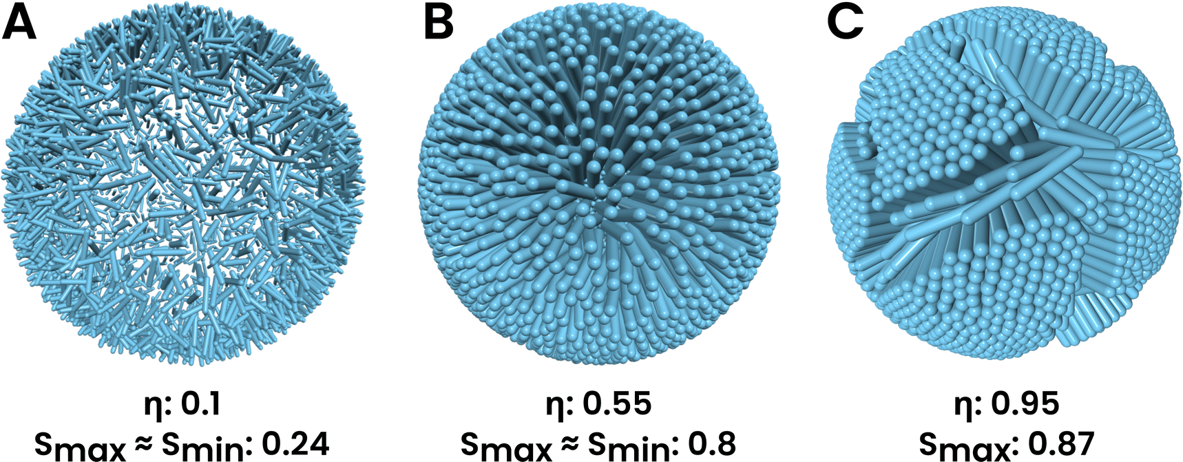 | ||
| Fig. 1 Different phases seen in the system: (A) the system shows a weakly nematic structure, where particles have a very small orientational correlation, but they show a preferred direction because of the presence of spherical confinement, which is the radially outward direction on the sphere, (B) highly orientationally ordered LC phase at medium packing fractions, where particles are directed radially outwards, (C) solid phase that occurs at high packing fractions and has multiple domains of high ordering separated by defect lines of low ordering. The ordering in the fluid phase increases with an increase in packing fraction. All simulations were done for A = 5. η = aρ is the packing fraction (a,ρ are the cross-sectional area of spherocylinders and surface density, respectively) and S is the nematic order parameter. | ||
The solid phase occurs at high packing fractions (η ≳ 0.65) (Fig. 1C) and shows a high degree of positional and orientational ordering. However, the ordering is not uniform across the surface of the sphere, and there exist domains of high crystalline ordering separated by line defects with low or no ordering.
The rest of the paper is organized as follows. In Section 2, we describe the model, the interaction potential, the constraints used, and the simulation details. In Section 3, we highlight the main results—the properties of the different phases, the nature of phase transitions between them, and their dependence on shape anisotropy and the topological defects in the solid phase. In Section 4, we discuss the results and their interpretations and implications, and conclude with possible future directions for this work.
2 Model and simulation details
The system we study is a collection of soft repulsive spherocylinders (right circular cylinders with hemispherical end caps), each having mass m. The length of the cylinder (or the core of the spherocylinder) is L, and the diameter of the hemispheres and the cylinder is D. Note that the total length of the spherocylinder would be L + D. The shape anisotropy of such a molecule is A = L/D. When A = 0, the spherocylinder would become a sphere. The aspect ratio, the ratio of total length to width, is A + 1. These SRS particles interact with each other with a generalization of the Weeks–Chandler–Anderson potential53 to non-spherical particles, in which the force acts along the line of shortest distance54 between the cores of the spherocylinders, as opposed to between the line joining their centers. This interaction potential is given as follows: | (1) |
|![[r with combining right harpoon above (vector)]](https://www.rsc.org/images/entities/b_char_0072_20d1.gif) | = R, | = R, | (2) |
![[v with combining right harpoon above (vector)]](https://www.rsc.org/images/entities/b_char_0076_20d1.gif) i·i = 0, i·i = 0, | (3) |
i and i are the center of mass position and velocity of the ith spherocylinder and the origin of the coordinate system is at the center of the sphere. The constraints are applied to each ith spherocylinder.
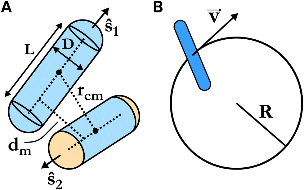 | ||
| Fig. 2 (A) Schematic diagram of the interaction between two SRS particles. The dashed line segment between the centers of the two hemispherical end caps on each SRS is called the core. ŝ1 and ŝ2 are the orientations of the two SRSs, respectively. rcm is the distance between the center of mass of the two SRSs while dm is the shortest distance between the cores. The force between these two particles depends on dm and acts along the shortest line segment between the two cores. The schematics apply to all pairs of particles. (B) Schematic of the spherical shell constraint on the SRSs. The center of mass lies on the surface of the sphere, while its translational velocities are tangential to the surface. | ||
We performed molecular dynamics (MD) simulations of this system in the constant number–volume–temperature (NVT) ensemble. We use the velocity Verlet integration algorithm55 to update the positions and velocities and an adaptation of the RATTLE algorithm56 to enforce the constraints. All quantities, thermodynamic and structural, are scaled by the system parameters ε and D and calculated in reduced units: temperature T* = kBT/ε, pressure P* = aP/(kBT), packing fraction η = aρ, where ρ = N/V is the density, N is the number of particles, V = 4πR2 is the surface area and a = πD2/4 is the cross-sectional area of the spherocylinder. In our calculations, we take kB = 1 and measure time in units of D(m/ε)1/2. The temperature of the system was maintained using a Berendsen thermostat57 with a temperature coupling time of τT = 0.05 for smaller densities and down to τT = 0.01 for larger densities.
Because of the constraint eqn (2), the translational degrees of freedom for the particles is 2. Therefore, pressure is calculated as:
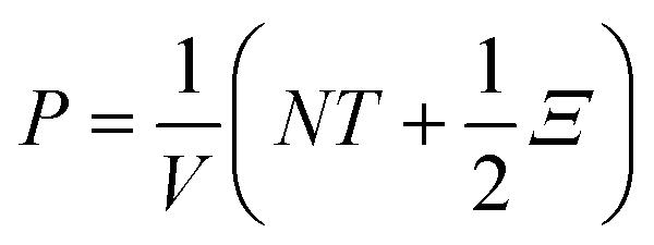 | (4) |
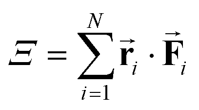 is the virial and
 ![[F with combining right harpoon above (vector)]](https://www.rsc.org/images/entities/b_char_0046_20d1.gif) i is the force acting on the ith particle due to interaction with all other particles. We prepared the initial state of the system with all particles evenly distributed on the surface of the sphere and having a coordination number of 6, with the use of a Fibonacci sphere construction.58 Initially, all particle orientations (ŝ) are along the outward normal to the surface. The translational and rotational velocities are given random values in accordance with the constraints. We performed the simulations for a system size of N = 2500 particles and shape anisotropy A = 5. After setting up the initial state, we run the simulation at T* = 5 for 4 × 10⁵ timesteps to equilibrate the system. Following this, we simulated the system for another 4 × 10⁵ timesteps while calculating and averaging the thermodynamic and structural quantities. We use an integration timestep of δt = 0.001 throughout the simulations. We simulate the system for a range of packing fractions (η) from 0.95 to 0.1. The shape anisotropy A = 5 and temperature T* = 5 were chosen such that the unconstrained 3D system would show all phases – isotropic, nematic, smectic A, and crystal – in this range of packing fractions.3,59 Therefore, working with these values will help us understand the effect of spherical constraints on the different phases as compared to 3 dimensional systems. We changed the packing fraction after each stage of the simulation process (equilibration and measurement) by changing the radius of the constraining sphere by an appropriate amount. Note that the system is not re-initialized after each state point simulation, and the end state of the previous stage becomes the starting point for the equilibration of the next stage. The equilibration is sufficiently long for the system to settle into its new steady state and not have any memory of the previous state. To check for finite size effects, if any, we have also performed simulations for a system size of N = 25
i is the force acting on the ith particle due to interaction with all other particles. We prepared the initial state of the system with all particles evenly distributed on the surface of the sphere and having a coordination number of 6, with the use of a Fibonacci sphere construction.58 Initially, all particle orientations (ŝ) are along the outward normal to the surface. The translational and rotational velocities are given random values in accordance with the constraints. We performed the simulations for a system size of N = 2500 particles and shape anisotropy A = 5. After setting up the initial state, we run the simulation at T* = 5 for 4 × 10⁵ timesteps to equilibrate the system. Following this, we simulated the system for another 4 × 10⁵ timesteps while calculating and averaging the thermodynamic and structural quantities. We use an integration timestep of δt = 0.001 throughout the simulations. We simulate the system for a range of packing fractions (η) from 0.95 to 0.1. The shape anisotropy A = 5 and temperature T* = 5 were chosen such that the unconstrained 3D system would show all phases – isotropic, nematic, smectic A, and crystal – in this range of packing fractions.3,59 Therefore, working with these values will help us understand the effect of spherical constraints on the different phases as compared to 3 dimensional systems. We changed the packing fraction after each stage of the simulation process (equilibration and measurement) by changing the radius of the constraining sphere by an appropriate amount. Note that the system is not re-initialized after each state point simulation, and the end state of the previous stage becomes the starting point for the equilibration of the next stage. The equilibration is sufficiently long for the system to settle into its new steady state and not have any memory of the previous state. To check for finite size effects, if any, we have also performed simulations for a system size of N = 25![[thin space (1/6-em)]](https://www.rsc.org/images/entities/char_2009.gif) 000.
000.
The ordering transitions are determined by calculating the nematic order parameter and the radial order parameter. The tensor order parameter is a traceless symmetric tensor Q defined as:
 | (5) |
![[n with combining right harpoon above (vector)]](https://www.rsc.org/images/entities/b_char_006e_20d1.gif) is the director of the ordered phase. In highly ordered states, S ≈ 1 and in highly disordered states, S ≈ 0. The radial order parameter quantifies how well the particles are aligned along their local radial direction and is defined as follows:
is the director of the ordered phase. In highly ordered states, S ≈ 1 and in highly disordered states, S ≈ 0. The radial order parameter quantifies how well the particles are aligned along their local radial direction and is defined as follows: | (6) |
Since the system in consideration has a spherical geometry, the nematic and radial order parameters can vary as a function of the position on the sphere. Therefore, we divide the system into 20 equally sized and shaped regions and calculate the order parameter for each of them separately. These 20 regions are the faces of an inscribed spherical icosahedron.
The orientational ordering is also quantified with the orientational correlation of the particles, which is a function of the geodesic angle θ, i.e. the angle subtended by the lines joining the center of the constraining sphere to two points on its surface. It is calculated as:
 | (7) |
 | (8) |
The positional ordering is also quantified with the use of the structure factor S(![[q with combining right harpoon above (vector)]](https://www.rsc.org/images/entities/b_char_0071_20d1.gif) ) defined as follows:
) defined as follows:
 | (9) |
3 Results
Below, we individually discuss the properties of each of the different phases observed in the system. The results and values reported here are for the simulation of a system with A = 5.0, T* = 5.0, and N = 2500, unless otherwise stated.3.1 Fluid phases
At very low packing fractions (η ≲ 0.35), the pressure of the system is small (Fig. 3A) and it exhibits a liquid crystalline fluid phase in which there is no positional order but very weak orientational order (Fig. 1A). The lack of positional order can be inferred from the radial distribution function g(θ) in Fig. 4A, which rises rapidly to 1 and saturates. The structure factor (Fig. 5A) for η ≤ 0.64 also does not show any peaks other than the central q = 0 peak, confirming the absence of positional ordering (see Fig. S1 in the ESI† for a structure factor for η = 0.3). The weak orientational ordering can be inferred from the nematic order parameter in Fig. 3B, the radial order parameter in Fig. 3C and the orientational correlation in Fig. 4B. The orientational correlation sharply decays to near 0 as θ increases from 0, and the nematic and radial order parameters take low values. We observe that the orientational ordering increases with the packing fraction. | ||
| Fig. 3 (A) Equation of state of the system, reduced pressure P* vs. packing fraction η of a system of 2500 particles with A = 5, with both compression and expansion simulation schemes. (B) Nematic order parameters S and (C) radial order parameter Sr as a function η for the same system and simulation schemes. The minimum and maximum are calculated over the 20 regions of the spherical surface. The closeness of the minimum and maximum indicates the degree of homogenous ordering across the system. A large difference between the maximum and minimum of the order parameters indicates inhomogeneous ordering. The high (maximum) values of S at high η indicate the appearance of crystalline domains, whereas the minimum values appear due to the defect lines that separate the two domains. Therefore, the disagreement between the line of maximum and minimum of the nematic order parameter is also an indicator of the appearance of the solid phase. Both plots are with T* = 5, A = 5, and N = 2500. | ||
 | ||
| Fig. 4 (A) Radial distribution function g(θ) as a function of the geodesic angle θ for low to medium packing fractions. At low packing fractions (η ≲ 0.35), there is no structuring at all. But at medium packing fractions (η ∼ 0.35–0.65), it shows short ranged spatial ordering and structure. (B) The orientational correlation OC(θ) as a function of the geodesic angle θ for the same range of packing fractions. At low packing fractions, the orientations are weakly correlated. At medium packing fractions, the sinusoidal orientational correlation shows that the particles are radially oriented. | ||
At medium packing fractions (η ∼ 0.35–0.65), there is an emergence of substantial orientational ordering. This can be inferred from the nematic and radial order parameters taking values of ∼0.8 and ∼1, respectively (Fig. 3B and C). The orientational ordering can also be understood from the form of orientational correlation which tends to a sinusoidal-like curve as the packing fraction increases. Such a curve indicates that, on average, the particles are aligned along the local radial direction. The structure factor (Fig. 5A) clearly shows that there is no positional ordering established in these packing fractions (η ∼ 0.35–0.65). The maximum and the minimum values of the nematic order parameter over the regions match closely, indicating homogeneity in the orientational ordering across the spherical monolayer. Therefore, we term this phase as a radially oriented two-dimensional liquid crystal (2D LC).
The istropic–nematic transition of SRSs and hard spherocylinders (HSCs) in 3D cases is of first order,2,60,61 where the equation of state changes discontinuously at phase transition points. To study the finite size effect for the system, we have performed simulations of a system of size N = 25000 i.e. 10 times the size of the initial system which we were studying. In this case also, we see the existence of the liquid crystalline phase at low to medium densities. Interestingly, this system does not show the deviation of the maximum and minimum values of the nematic or radial order parameter within the calculated range of densities. To determine the nature of the phase transitions, we have also performed the simulations for a system of size N = 2500 with both expanding and contracting schemes. That is, the system is simulated for each state point and then expanded to cover a range of packing fractions (η: 0.95–0.1) Following the simulation of the lowest packing fraction (η = 0.1) state point, the system is then compressed to cover the same range in the reverse direction. The equation of state and order parameters of this simulation scheme are shown in Fig. 3. If the transition is discontinuous, we expect to see a difference in the expansion and compression curves, like a hysteresis curve. However, in both these plots, we see that for a range of low (η ≲ 0.35) to medium packing fractions (η ∼ 0.35–0.65), the curve obtained by compression exactly follows the curve obtained by expansion. The disagreement that is seen at higher packing fractions is due to the liquid crystal–solid phase transition.
 | ||
| Fig. 5 Emergence of positional ordering in the solid phase. (A) Structure factor of a region in the nematic phase just below the phase transition point and it shows no long-range ordering. (B–D) Structure factors of a representative domain in the solid phase. As the packing fraction increases into the solid phase (η ≳ 0.65), the range of ordering also increases, indicated by the number of bright points in the plot. Before calculation of these structure factors, the region was first transformed such that its center of mass coincides with the origin and then flattened onto the xy plane. | ||
3.2 The solid phase
The solid phase occurs at high packing fractions (η ≳ 0.65), and shows high positional and orientational ordering within crystalline domains (Fig. 1C). These domains are separated by line defects having low or no order. To determine the nature of packing in the domains of the solid phase, we performed structure factor calculations on a representative domain of the state of the system for a range of packing fractions. Fig. 5 shows the emergence of well-set translational ordering as the packing fraction is increased, as understood by the increasing number of rings in the plot. The structure factor (Fig. 5) shows that the domains are crystalline in nature with hexagonal packing of the particles.The phase transition from a 2D LC phase to a solid phase is a first-order transition, as indicated by the disagreement or hysteresis in the equation of state during the expansion and compression simulation regimes (Fig. 3A). For sufficiently high shape anisotropy, the phase transition from 2D LC to solid is also identified by the deviation of the maximum and minimum values of the order parameters across the spherical monolayer (Fig. 3B and C). The LC to solid phase transition point depends on anisotropy A and temperature T*. The phase transition also depends on the number of particles N due to the finite-sized nature of the system. For an anisotropy of A = 5, a temperature of T* = 5, and a system size of N = 2500, the transition point occurs at η ∼ 0.66 and P* ∼ 16.094.
3.3 Topological defects in the solid phase
The defects in solids are known to exist in grain boundaries or at the edges of grains. These kinds of defects exist only in polycrystalline solids and are generally absent in monocrystalline solids at low temperatures. However, in a spherical shell, it is impossible to have a defect-free crystal due to its positive Gaussian curvature. 2D positional ordering is incompatible with surfaces having the Gaussian curvature and is frustrated due to the well-known Euler's theorem of topology as well as the fact that straight lines (geodesics) on spheres are not parallel.62–64 In fact, in the limit L/D → 0, i.e. for spherical particles, experimental observations have confirmed the formation of 12 isolated ‘seas’ of defects, compatible with icosahedron symmetry on the surface of the sphere.65 For the cases of spherocylinders, it is due to the line defects that crystalline domains of high positional and orientational order can exist in the spherical shell i.e. some particles move out of the way to form line defects which allows the other particles to come closer and form tighter packing in a domain. At small system sizes and high spherical curvatures, the line defects consist of particles that are oriented at a large angle from the directors of the neighboring crystal domains and are nearly parallel to the surface of the constraining sphere (Fig. 6A). Therefore, the deviation of the maximum and minimum of the nematic order parameter of the regions implies the existence of a solid phase; however, the converse need not be true. In addition to these orientational line defects, there also exist disclinations (defects along the edges of the domains which have a coordination number other than six) (Fig. 6A). Furthermore, there also exist point defects in the interior of domains. These are dislocations due to which one particle has a higher coordination number and another particle has a lower coordination number compared to their neighbors (Fig. 6A). However, at very large system sizes, the line defects are of a different nature. The orientational defects no longer occur. The defect lines separating domains consist only of positional dislocation defects (Fig. 6B). This occurs because the low curvature at high system sizes causes less frustration in the ordering of the particles and it can better accommodate crystalline packing. We also observe the appearance of grain boundary scars that appear and terminate within the spherical surface itself (Fig. 6B). Interestingly, one more important ratio for our system is L/R, which has an implication on the splay strain of the system. When L/R is large, the splay strain for the particles is large, and the tail ends of the rods feel strong repulsive forces inside the sphere, which results in the formation of orientational defects. But as we reduce the value of L/R, the splay strain decreases, and the rods can be accommodated on the sphere without the formation of orientational defects. This is also seen in Fig. 6A and B. At constant high packing fractions, as N increases, R also increases, decreasing the splay strain, and resulting in the absence of orientational defects. Therefore, increasing the number of particles to N = 25000 not only confirms the absence of isotropic phase66 but also the effect of the splay strain of the system. It demonstrates the importance of the dimensionless ratio L/R. In the limit of infinite system size, the curvature tends to zero, and the system becomes an unconstrained 2D system in which there can be perfect crystallinity.
 | ||
| Fig. 6 Defects seen in the solid phase of the system at two different system sizes (A) N = 2500 particles and (B) N = 25000 particles, with A = 5. The particles are colored based on the coordination number (CN) and defect type. Both systems show large regions with a coordination number of 6, separated by defect lines, albeit of different types. The defect lines in the smaller system are formed by orientational defects and disclinations, while that of the larger system is formed by dislocation defects. They also form grain boundary scars. | ||
3.4 Other shape anisotropies
The phases of a system of a soft monolayer67,68 of spherocylinders naturally depend on the shape anisotropy of the rods in addition to the temperature, density, and curvature of the constraining sphere. So far, we have looked at systems at a constant temperature of T* = 5, and constant shape anisotropy of A = L/D = 5 at varying packing fractions. To understand the dependence of the phases on the shape anisotropy, we have also simulated the system over the same range of packing fractions for various other shape anisotropies (A: 3–7).We observe that the phase transition from 2D LC to solid occurs at lower packing fractions as the shape anisotropy is increased, as shown by the decreasing curve in Fig. 7 (LC–solid). For example, for A = 4, the transition occurs for a packing fraction of ∼0.71. In contrast, for A = 7, the transition occurs at a packing fraction of ∼0.49. This is expected because when the shape anisotropy increases, the tail end of the rods in the interior of the constraining sphere interacts at closer distances and experiences stronger repulsive forces. Due to this, the orientational defect lines would form at a lower packing fraction. This is the effect of the topological constraint. For bulk 3D cases, the critical density for the smectic to crystalline phase transition does not show similar dependence on the shape anisotropy of the particles. (Fig. 7 Bulk Sm–K). In 3D bulk, the smectic to crystalline transition is mainly controlled by the packing fraction or density. Interestingly, the 2D LC–solid phase transition packing fraction shows a similar decreasing behavior as the 3D bulk isotropic to nematic transition density.
 | ||
| Fig. 7 The shape anisotropy dependence of the packing fraction at the phase boundary η* for the transition from the 2D liquid crystal to a solid (LC–solid) for a spherical monolayer. Also shown for are the 3D bulk transitions, namely isotropic–nematic (I–N), nematic–smectic (N–Sm) and smectic–crystal (Sm–K). The packing fraction for SRSs in bulk 3D is defined as η = vhscρ, where ρ = N/V, vhsc = πD2(D/6 + L/4). The data for the bulk transitions are taken from Cuetos and Martinez-Haya.3 All transition packing fractions shown here are for melting from the phase with higher order to the phase with lower order. | ||
Below a certain critical shape anisotropy Ac, orientational defects are no longer observed, and the LC–solid transition becomes continuous. This can be seen in Fig. 8 (also see Fig. S3 in the ESI†), which shows that for A = 3, the maximum and minimum nematic and radial order parameter lines match each other throughout, while for A = 4, they deviate at high packing fractions. However, other defects, namely disclinations, still exist due to the curvature of the sphere. The homogeneity of the nematic order parameter for A = 3 indicates that there are no particles with large orientational deviations from their neighbors. This implies the absence of orientational defects. The continuous nature of the LC–solid transition is seen from the absence of any disagreement or hysteresis in the equation of state during compression and expansion for A = 3 (Fig. S4 in the ESI†). However, there is a disagreement between the compression and expansion equations of state curves for A = 4. There is also a gradual emergence of short-ranged hexagonal positional order with increasing packing fraction for A = 3 even without any discontinuity in the equation of state (Fig. S5 in the ESI†).
 | ||
| Fig. 8 Nematic order parameter S as a function of the packing fraction η for (A) shape anisotropy, A = 3, and (B) A = 4. Both are calculated for systems with T* = 5 and N = 2500. For A = 3, there is no large difference between the maximum and minimum values of the order parameters during the liquid crystal to solid phase transition while there is a large difference in the case of A = 4. This indicates that there is indeed a critical shape anisotropy 3 < Ac < 4 below which the LC–solid transition is continuous. | ||
Both of these facts indicate that for T* = 5 and N = 2500, 3 < Ac < 4. After further study, we find that the critical shape anisotropy lies in the interval Ac ∈ (3.47, 3.487). Below the critical shape anisotropy, the rods do not experience sufficient repulsive interactions at their tail ends in the interior of the sphere. Due to this, all of the rods can be accommodated in a radially aligned configuration and there is no need for orientational defects to arise. And therefore, there is no large difference in the maximum and minimum values of the nematic order parameter such as that seen above the critical shape anisotropy. Furthermore, below Ac, the appearance of the solid phase is no longer synonymous with the appearance of orientational defects and a deviation in the maximum and minimum of the order parameters.
We note that for shape anisotropy values lower than the critical value (A < Ac), orientational defects, and hence a heterogeneity in the order, may appear only if the packing fraction is extremely high (>1). However, such high packing fractions also result in extremely high pressures due to the sharply increasing pressure as a function of the packing fraction (Fig. 3A). Therefore, we limit our study to reasonable packing fractions in the range of 0–1. Moreover, in the limit that A = L/D → 0, the spherocylinder reduces to a simple sphere. In this limit, orientational defects are not possible even at arbitrarily large packing fractions. Additionally, for hard spheres on the surface of a sphere, the fluid–solid transition is a continuous one;69,70 the continuous nature of the LC–solid transition below Ac is consistent with this.
At medium packing fractions (η ∼ 0.35–0.65), since the particle orientation is almost normal to the surface of the sphere, the shape of the projection of the rods on the spherical surface is like a disk. Therefore, it would be of interest to compare the results of melting of disk-like particles in 2 dimensions. Simulation studies show that the melting of hard disks in two dimensions undergoes two different transitions, a liquid to hexatic first-order transition and a hexatic to solid continuous transition.71 The liquid-hexatic co-existence is shown to occur near the packing fraction η ∼ 0.71.68 For soft disks, the nature of the transitions can alter depending on the strength of the potential.72 In contrast, the LC–solid transition for spherocylinders in a spherical monolayer does depend on the shape anisotropy of the particles.
In 3D bulk, the presence of the nematic phase depends on the shape anisotropy and may not be observed below the minimum shape anisotropy.3 This is also seen in a system consisting of a mixture of active and passive spherocylinders, in which the presence of the nematic phase depends on the shape anisotropy and the relative activity.73 However, we observe a 2D LC phase for all values of A that we considered in our simulations. i.e. A = 3–7.
4 Conclusions
In this work, we have studied the phase behavior of soft spherocylinders whose centers of masses are constrained to move on the surface of a sphere. We showed that the isotropic phase is absent for such a system of a monolayer of SRS particles and the orientational ordering of the system increases continuously as density is increased. The LC phase at medium densities shows a hedgehog-particle-like structure where the rods are aligned normally to the surface of the sphere. At even higher packing fractions, there appears a solid phase consisting of crystalline domains of high orientational and hexagonal close packing, separated by defect lines. We show that the transition from a 2D liquid crystal to a solid is a first-order phase transition. This phase transition from a liquid crystal to a solid depends not only on the temperature and density of the system, but also on the curvature of the constraining spherical surface and the shape anisotropy of the rods. Keeping the other variables at a fixed value, there appears a critical value of the shape anisotropy below which the LC–solid phase transition is continuous, and orientational defects can no longer be observed. We also found that the LC–solid phase transition density (packing fraction) decreases with increasing shape anisotropy of the particles, similar to the case of isotropic–nematic transition in 3D bulk. We observed various point and line defects in the solid phase, which appear due to the curved geometry of the sphere. Interestingly, the point defects can have coordination numbers of not only 5 and 7 (which is the case for spherical particles on a spherical surface74) but also 4 and 8. For small system sizes with high curvatures of the constraining sphere, orientational defects and disclinations appear, whereas for large system sizes with low curvatures, we see dislocations and grain boundary scars emerging in the system.So far, there have been several studies to understand the system of colloidal rod-like particles constrained to move tangent to the surface of a sphere.38,42,44 While Chen et al.25 have studied substantially more complex systems of spherically constrained rod-like particles, experiments with particles free to rotate, such as in our system, would be very insightful and beneficial to the field. Such experiments, with control on the density of particles on the sphere, will tell us how such a system would behave in the real world.
We see several theoretical and computational future directions of this work involving the examination of phase behaviors of similar but modified systems. Constraining rods on other manifolds such as ellipsoids or toroids could give rise to distinct phases and defect structures due to the different properties of the manifolds. Chiral particles in 3D bulk show twist deformation and cholesteric phases,75,76 but such particles in 2D cannot show twist, and hence cholesteric phases are absent. However, if they are constrained in a spherical shell like in this work, they may be able to twist and show cholesteric phases. Spherocylinders in bulk show a nematic phase for packing fractions in the range of ∼0.5–0.659,60 and more ordered smectic and crystal phases at higher packing fractions. This system of a spherical monolayer of spherocylinders also shows a liquid crystalline phase around the same range of packing fractions. Therefore, it might be possible for a constrained spherical shell of spherocylinders in the ordered phase to exist in the bulk of unconstrained spherocylinders. In such a system the bulk particles close to the sphere will try to align with the local spherical director and particles far away try to be parallel. The transition from one to another is formed by defects and should be studied in detail. A system of active rods on such constraining manifolds, in which the non-equilibrium behavior of a mixture of active and passive rods on a spherical geometry may give rise to novel structures and phase separations. Our future plan involves the study of such systems.
Conflicts of interest
There are no conflicts to declare.Acknowledgements
DR thanks KVPY, DST, India, for a scholarship. JM thanks MHRD, India, for a fellowship. PKM thanks DST, India, for financial support and SERB, India (IPA/2020/000034), and DAE, India, for funding and computational support. We would also like to thank Prof. Sriram Ramaswamy for the insightful discussions.References
- L. Onsager, Ann. N. Y. Acad. Sci., 1949, 51, 627–659 CrossRef CAS.
- P. Bolhuis and D. Frenkel, J. Chem. Phys., 1997, 106, 666–687 CrossRef CAS.
- A. Cuetos and B. Martinez-Haya, Mol. Phys., 2015, 113, 1137–1144 CrossRef CAS.
- M. A. Bates and D. Frenkel, J. Chem. Phys., 2000, 112, 10034–10041 CrossRef CAS.
- M. S. Al-Barwani and M. P. Allen, Phys. Rev. E: Stat., Nonlinear, Soft Matter Phys., 2000, 62, 6706 CrossRef CAS.
- A. Cuetos, B. Martinez-Haya, S. Lago and L. Rull, Phys. Rev. E: Stat., Nonlinear, Soft Matter Phys., 2003, 68, 011704 CrossRef CAS.
- B. Martnez-Haya and A. Cuetos, J. Phys. Chem. B, 2007, 111, 8150–8157 CrossRef.
- M. Marechal, A. Cuetos, B. Martnez-Haya and M. Dijkstra, J. Chem. Phys., 2011, 134, 094501 CrossRef.
- R. van Roij, P. Bolhuis, B. Mulder and D. Frenkel, Phys. Rev. E: Stat., Nonlinear, Soft Matter Phys., 1995, 52, R1277 CrossRef CAS PubMed.
- D. J. Earl, J. Ilnytskyi and M. R. Wilson, Mol. Phys., 2001, 99, 1719–1726 CrossRef CAS.
- M. Rotunno, T. Bellini, Y. Lansac and M. A. Glaser, J. Chem. Phys., 2004, 121, 5541–5549 CrossRef CAS.
- S. Dussi, M. Chiappini and M. Dijkstra, Mol. Phys., 2018, 116, 2792–2805 CrossRef CAS.
- M. Adams, Z. Dogic, S. L. Keller and S. Fraden, Nature, 1998, 393, 349–352 CrossRef CAS.
- R. van Roij, B. Mulder and M. Dijkstra, Phys. A, 1998, 261, 374–390 CrossRef CAS.
- H. E. Bakker, S. Dussi, B. L. Droste, T. H. Besseling, C. L. Kennedy, E. I. Wiegant, B. Liu, A. Imhof, M. Dijkstra and A. van Blaaderen, Soft Matter, 2016, 12, 9238–9245 RSC.
- S. Dussi and M. Dijkstra, Nat. Commun., 2016, 7, 1–10 Search PubMed.
- S. Dussi, N. Tasios, T. Drwenski, R. Van Roij and M. Dijkstra, Phys. Rev. Lett., 2018, 120, 177801 CrossRef CAS.
- P.-G. De Gennes and J. Prost, The physics of liquid crystals, Oxford University Press, 1993 Search PubMed.
- S. C. McGrother, D. C. Williamson and G. Jackson, J. Chem. Phys., 1996, 104, 6755–6771 CrossRef CAS.
- P. K. Maiti, Y. Lansac, M. A. Glaser and N. A. Clark, Phys. Rev. Lett., 2002, 88, 065504 CrossRef.
- Y. Lansac, P. K. Maiti, N. A. Clark and M. A. Glaser, Phys. Rev. E: Stat., Nonlinear, Soft Matter Phys., 2003, 67, 011703 CrossRef.
- A. Patti and A. Cuetos, Phys. Rev. E: Stat., Nonlinear, Soft Matter Phys., 2012, 86, 011403 CrossRef.
- V. N. Manoharan, Solid State Commun., 2006, 139, 557–561 CrossRef CAS.
- D. Lee and D. A. Weitz, Adv. Mater., 2008, 20, 3498–3503 CrossRef CAS.
- H.-Q. Chen, X.-Y. Wang, H. K. Bisoyi, L.-J. Chen and Q. Li, Langmuir, 2021, 37, 3789–3807 CrossRef CAS.
- J. M. Collinson, L. Morris, A. I. Reid, T. Ramaesh, M. A. Keighren, J. H. Flockhart, R. E. Hill, S.-S. Tan, K. Ramaesh and B. Dhillon, et al. , Dev. Dyn., 2002, 224, 432–440 CrossRef.
- P. J. Keller, A. D. Schmidt, J. Wittbrodt and E. H. Stelzer, Science, 2008, 322, 1065–1069 CrossRef CAS PubMed.
- L. Janssen, A. Kaiser and H. Löwen, Sci. Rep., 2017, 7, 1–13 CrossRef CAS.
- J. O. Law, A. G. Wong, H. Kusumaatmaja and M. A. Miller, Mol. Phys., 2018, 116, 3008–3019 CrossRef CAS.
- J. O. Law, J. M. Dean, M. A. Miller and H. Kusumaatmaja, Soft Matter, 2020, 16, 8069–8077 RSC.
- S. A. Akram, A. Behera, P. Sharma and A. Sain, Soft Matter, 2020, 16, 10310–10319 RSC.
- H. Poincaré, J. Math. Pures Appl., 1885, 4, 167–244 Search PubMed.
- L. Brouwer, Math Ann., 1912, 71, 97–115 CrossRef.
- T. Lubensky and J. Prost, J. Phys. II, 1992, 2, 371 CrossRef CAS.
- M. A. Bates, J. Chem. Phys., 2008, 128, 104707 CrossRef PubMed.
- S. Dhakal, F. J. Solis and M. O. De La Cruz, Phys. Rev. E: Stat., Nonlinear, Soft Matter Phys., 2012, 86, 011709 CrossRef.
- H. Shin, M. J. Bowick and X. Xing, Phys. Rev. Lett., 2008, 101, 037802 CrossRef PubMed.
- T. Lopez-Leon, A. Fernandez-Nieves, M. Nobili and C. Blanc, Phys. Rev. Lett., 2011, 106, 247802 CrossRef.
- F. Smallenburg and H. Löwen, J. Chem. Phys., 2016, 144, 164903 CrossRef.
- E. Allahyarov, A. Voigt and H. Löwen, Soft Matter, 2017, 13, 8120–8135 RSC.
- G. A. DeVries, M. Brunnbauer, Y. Hu, A. M. Jackson, B. Long, B. T. Neltner, O. Uzun, B. H. Wunsch and F. Stellacci, Science, 2007, 315, 358–361 CrossRef CAS.
- A. Fernández-Nieves, V. Vitelli, A. S. Utada, D. R. Link, M. Márquez, D. R. Nelson and D. A. Weitz, Phys. Rev. Lett., 2007, 99, 157801 CrossRef.
- D. R. Nelson, Nano Lett., 2002, 2, 1125–1129 CrossRef CAS.
- S. Zhou, J. Fan, S. S. Datta, M. Guo, X. Guo and D. A. Weitz, Adv. Funct. Mater., 2013, 23, 5925–5929 CrossRef CAS.
- T. Lopez-Leon, V. Koning, K. Devaiah, V. Vitelli and A. Fernandez-Nieves, Nat. Phys., 2011, 7, 391–394 Search PubMed.
- P. Poulin, H. Stark, T. Lubensky and D. Weitz, Science, 1997, 275, 1770–1773 CrossRef CAS PubMed.
- I. Musevic, M. Skarabot, U. Tkalec, M. Ravnik and S. Zumer, Science, 2006, 313, 954–958 CrossRef CAS.
- Q. Liu, B. Senyuk, M. Tasinkevych and I. I. Smalyukh, Proc. Natl. Acad. Sci. U. S. A., 2013, 110, 9231–9236 CrossRef CAS.
- B. Senyuk, Q. Liu, S. He, R. D. Kamien, R. B. Kusner, T. C. Lubensky and I. I. Smalyukh, Nature, 2013, 493, 200–205 CrossRef CAS.
- A. Nych, U. Ognysta, M. Škarabot, M. Ravnik, S. Žumer and I. Muševič, Nat. Commun., 2013, 4, 1–8 Search PubMed.
- P. M. Chaikin, T. C. Lubensky and T. A. Witten, Principles of condensed matter physics, Cambridge university press Cambridge, 1995, vol. 10 Search PubMed.
- J. H. Bahng, B. Yeom, Y. Wang, S. O. Tung, J. D. Hoff and N. Kotov, Nature, 2015, 517, 596–599 CrossRef CAS PubMed.
- J. D. Weeks, D. Chandler and H. C. Andersen, J. Chem. Phys., 1971, 54, 5237–5247 CrossRef CAS.
- C. Vega and S. Lago, Comput. Chem., 1994, 18, 55–59 CrossRef CAS.
- W. C. Swope, H. C. Andersen, P. H. Berens and K. R. Wilson, J. Chem. Phys., 1982, 76, 637–649 CrossRef CAS.
- H. C. Andersen, J. Comput. Phys., 1983, 52, 24–34 CrossRef CAS.
- H. J. Berendsen, J. v Postma, W. F. Van Gunsteren, A. DiNola and J. R. Haak, J. Chem. Phys., 1984, 81, 3684–3690 CrossRef CAS.
- R. Swinbank and R. James Purser, Q. J. R. Meteorol. Soc., 2006, 132, 1769–1793 CrossRef.
- J. Chattopadhyay, S. Pannir-Sivajothi, K. Varma, S. Ramaswamy, C. Dasgupta and P. K. Maiti, Phys. Rev. E, 2021, 104, 054610 CrossRef CAS.
- A. Cuetos, B. Martnez-Haya, L. Rull and S. Lago, J. Chem. Phys., 2002, 117, 2934–2946 CrossRef CAS.
- A. Cuetos, B. Martinez-Haya, S. Lago and L. Rull, J. Phys. Chem. B, 2005, 109, 13729–13736 CrossRef CAS.
- J.-F. Sadoc and R. Mosseri, Geometrical frustration, 1999 Search PubMed.
- M. J. Bowick and L. Giomi, Adv. Phys., 2009, 58, 449–563 CrossRef CAS.
- G. M. Grason, J. Chem. Phys., 2016, 145, 110901 CrossRef.
- R. E. Guerra, C. P. Kelleher, A. D. Hollingsworth and P. M. Chaikin, Nature, 2018, 554, 346–350 CrossRef CAS.
- P. Siders, Mol. Phys., 1989, 68, 1001–1013 CrossRef CAS.
- Y. Martnez-Ratón, S. Varga and E. Velasco, J. Chem. Phys., 2014, 140, 204906 CrossRef.
- S. Varga, Y. Martnez-Ratón, E. Velasco, G. Bautista-Carbajal and G. Odriozola, Phys. Chem. Chem. Phys., 2016, 18, 4547–4556 RSC.
- S. P. Giarritta, M. Ferrario and P. Giaquinta, Phys. A, 1992, 187, 456–474 CrossRef.
- A. Pérez-Garrido and M. Moore, Phys. Rev. B: Condens. Matter Mater. Phys., 1998, 58, 9677 CrossRef.
- E. P. Bernard and W. Krauth, Phys. Rev. Lett., 2011, 107, 155704 CrossRef PubMed.
- S. C. Kapfer and W. Krauth, Phys. Rev. Lett., 2015, 114, 035702 CrossRef.
- J. Chattopadhyay, S. Ramaswamy, C. Dasgupta and P. K. Maiti, Two-temperature activity induces liquid-crystal phases inaccessible in equilibrium, arXiv, 2022, preprint, arXiv:2205.00667 DOI:10.48550/ARXIV.2205.00667.
- J.-P. Vest, G. Tarjus and P. Viot, Mol. Phys., 2014, 112, 1330–1335 CrossRef CAS.
- R. D. Kamien and J. V. Selinger, J. Phys.: Condens. Matter, 2001, 13, R1 CrossRef CAS.
- I. Dierking, Symmetry, 2014, 6, 444–472 CrossRef.
Footnote |
| † Electronic supplementary information (ESI) available. See DOI: https://doi.org/10.1039/d2sm00799a |
| This journal is © The Royal Society of Chemistry 2023 |