
Nanosized NiFeSe2/NiCo2O4 hierarchical arrays on Ni foam as an advanced electrocatalyst for hydrogen generation†
Mahboubeh
Tasviri
 *a,
Sahar
Shekarabi
a,
Davood
Taherinia
*b and
Mohammad Amin
Zare Pour
a
*a,
Sahar
Shekarabi
a,
Davood
Taherinia
*b and
Mohammad Amin
Zare Pour
a
aDepartment of Physical Chemistry, Faculty of Chemistry and Petroleum Sciences, Shahid Beheshti University, Tehran, Iran. E-mail: m_tasviri@sbu.ac.ir
bDepartment of Chemistry, Sharif University of Technology, Tehran, Iran. E-mail: taherinia@sharif.edu
First published on 16th November 2022
Abstract
The rational design of composite catalysts is critically essential for electrochemical water splitting. Here, we report on a novel hierarchical composite that comprises NiFeSe2 nanoparticles and NiCo2O4 nanoflakes supported on nickel foam (NF) as an efficient electrocatalyst for the hydrogen evolution reaction (HER). The conjunction of the NiFeSe2 nanoparticles and NiCo2O4 nanoflakes introduces a new synergistic effect for the HER, resulting in an improved NiCo2O4 catalyst. The as-prepared NiFeSe2/NiCo2O4/NF electrode exhibited an enhanced HER activity, with a low overpotential of 83 mV at a current density of 10 mA cm−2, a low Tafel slope of 45 mV dec−1, and an excellent long-term electrochemical stability in alkaline media. This hierarchical architecture is instrumental in exposing the catalytically active sites, boosting mass transport, and speeding up the release of generated hydrogen bubbles from the electrode surface. This research offers a promising way for the electrocatalytic performance of the catalysts toward large-scale water splitting.
1 Introduction
The increasing demand for energy which results in the wide use of fossil fuels has driven tremendous effort to find an environmentally friendly and renewable energy source. Hydrogen fuel has attracted considerable attention because of its high energy density and its production from renewable sources.1–4 There have been various conventional pathways for producing hydrogen, including steam reforming and partial oxidation. However, these methods require technologically demanding operational conditions and also require non-renewable fossil fuels as feedstock.5–7 Generating clean energy through electro/photo-catalytic methods has been one of the top priorities for the scientific community in recent decades. In this regard, electrochemical water splitting is a promising green technology for generating hydrogen from water.1,8,9Although the kinetics of electrochemical water splitting in an alkaline medium is slow, it is one of the most efficient and promising methods to achieve sustainable hydrogen production, and more research is being conducted to improve it. Water splitting is divided into two half-reactions: the hydrogen evolution reaction (HER) and the oxygen evolution reaction (OER).10,11
From the viewpoint of catalyst design for the HER, all approaches for material engineering applied to catalysts should aim to enhance the reaction kinetics through various paths, including depressing the water dissociation barrier, optimizing the catalyst–H interaction, and increasing the number of active sites. Several practical approaches can achieve this goal in material manufacturing, including dual-site and electronic structure engineering.12,13 Such design strategies are aimed at not only promoting the interaction between the active sites and particular intermediates, but also at reducing the overall energy barrier of the reaction.
Although precious/noble metal-based (e.g., Pt and Pd) materials exhibit great electrocatalytic activity in the HER due to their low overpotentials, high exchange current densities, and outstanding stability, their scarcity and high cost severely restrict their use for large-scale applications. Thus, it is necessary to design a low-cost, robust, efficient, and earth-abundant electrocatalyst.
Over the past few decades, the emergence of new synthesis techniques has led to the rapid development of earth-abundant and cost-effective transition metal dichalcogenides, chalcogenides, nitrides, selenides, and phosphides with various morphologies.14–18 It has been shown that many transition metal-based materials exhibit appropriate interaction with H.14–16
Extensive research on various electrocatalysts for the HER has shown transition metal oxides (TMOs) to be highly efficient catalysts. This is accomplished by using different TM-based materials to improve their electrocatalytic performance by synthesizing heterostructures on a porous 3D substrate, such as nickel foam (NF). In particular, TMOs with spinel structures have been thoroughly studied; they have shown promising performance as electrode materials for H2 generation because of their several desirable features, such as controllable synthesis methods, good electron conductivity, minimal toxicity, rich redox chemistry, stability, relative abundance and low-cost.18–20
As a significant member of the TMOs, NiCo2O4, a multiple oxidation state ternary metal oxide, has displayed promise when employed in batteries and supercapacitors. Exceptional features like controllable structures, high conductivity, and a large density of electrochemically active sites impart superior electrocatalytic activity to NiCo2O4.19,21–25 However, the utilization of NiCo2O4 as a bifunctional electrocatalyst in water splitting has been rarely reported.26–28
Furthermore, several studies have shown that well-arranged microstructures of Ni-based selenides are highly active and stable catalysts for the HER and OER.26 Moreover, Lu and Smith revealed that iron incorporation increases the active site numbers in nickel-based compounds in general, promoting electrocatalytic activities.29,30 Wang et al. reported that compared to Ni-based nanosheet precursors, NiFe-based nanosheet precursors, and porous NiSe2 nanosheets, porous (Ni0.75Fe0.25)Se2 nanosheets exhibit superior electrocatalytic activity due to their porous nanostructure and good electronic conductivity.31,32
In the present investigation, we report on the design of a bifunctional system based on the NiCo2O4 nanoflakes and NiFeSe2 nanoparticles on NF to take advantage of the distinctive properties of NiCo2O4 and desired features of NiFeSe2. First, the spinel-based NiCo2O4 nanoflakes were synthesized using a typical hydrothermal method, and then NiFeSe2 was obtained with the aid of a general solvothermal process and direct selenization. The hierarchal NiFeSe2/NiCo2O4/NF electrode exhibited excellent HER activity, with a low overpotential of 83 mV at a current density of 10 mA cm−2 and a low Tafel slope of 45 mV dec−1. This electrode also maintained excellent stability during an 8 h measurement period in an alkaline medium. The performance of the NiFeSe2/NiCo2O4/NF electrode can be attributed to the synergistic effect resulting from the combination of the said materials, which resulted in good electronic conductivity and a large electrochemically active surface area.
2 Experimental
2.1. Materials
Ni(NO3)2·6H2O, Co(NO3)2·6H2O, selenium powder, and KOH were purchased from Sigma-Aldrich. CO(NH2)2, NH4F, hydrazine, dimethylformamide (DMF), ethylene glycol (EG), and Fe(NO3)2·6H2O were purchased from Merck. All chemicals were used as received without further purification.Ni foam (NF) was purchased from Nanosize Company, Iran. NF substrates (0.75 cm × 0.5 cm rectangles with a thickness of 0.3 mm) were treated with HCl 12 M for 5 min, rinsed with extra amounts of deionized (DI) water and ethanol, and dried by purging with nitrogen at room temperature before use.
2.2. Preparation of NiCo2O4/NF
As schematically shown in Fig. 1A, NiCo2O4/NF was prepared by a one-step hydrothermal process. In a typical synthesis, 1.7 × 10⁻² mmol of Ni(NO3)2·6H2O, 6.6 × 10⁻² mmol of Co(NO3)2·6H2O, 3.0 × 10⁻² mmol of NH4F, and 7.5 × 10⁻² mmol of CO(NH2)2 were dissolved in 100 mL DI water and sonicated for 10 min at room temperature. Then, the solution was transferred into a 100 mL Teflon-lined steel autoclave, and an NF substrate was vertically immersed into the solution. After that, the mixture was hydrothermally treated at 120 °C for 5 h. The as-prepared sample was thoroughly rinsed with DI water and ethanol and dried at room temperature. Finally, the sample was annealed at 350 °C in a nitrogen atmosphere for 2 h with a heating rate of 1 °C min−1 to crystallize the coated NiCo2O4 film.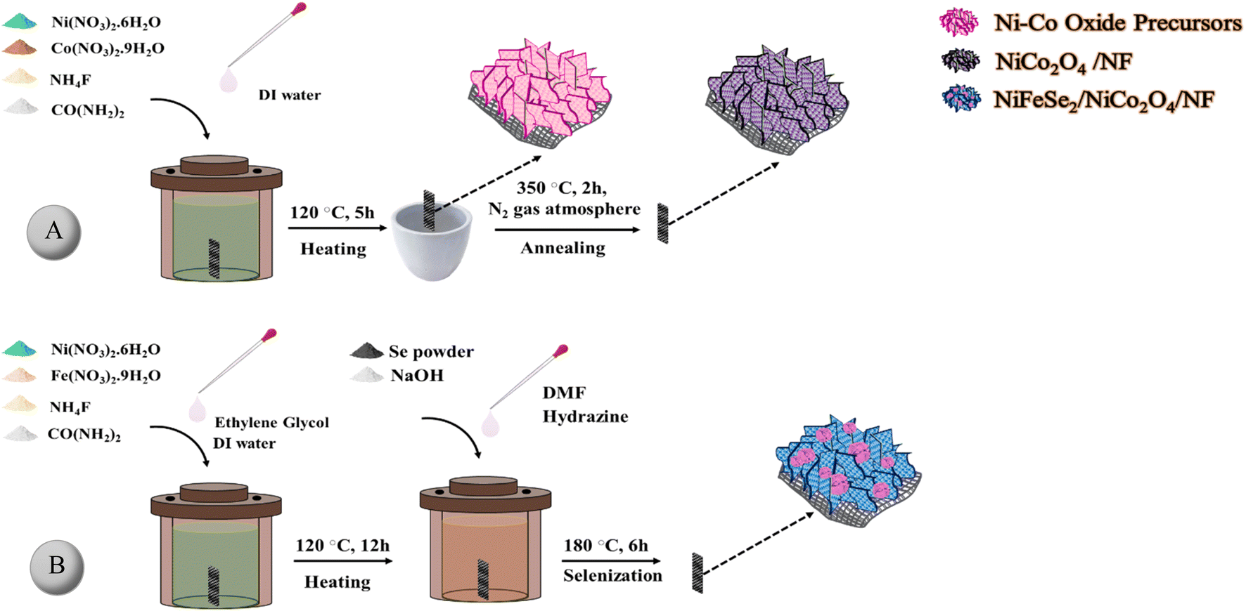 | ||
| Fig. 1 Schematic illustration of the preparation of (A) NiCo2O4/NF and (B) NiFeSe2/NiCo2O4/NF samples. | ||
2.3. Preparation of NiFeSe2/NiCo2O4/NF
A two-step reductive solvothermal process was used to prepare the NiFeSe2 layer (Fig. 1B). In the first stage, nickel–iron layered double hydroxide (NiFe-LDH) was synthesized by the solvothermal method, and then in the second stage, NiFeSe2 was prepared via a solvothermal selenization treatment. In a typical synthesis, 1.5 mmol of Ni(NO3)2·6H2O, 0.5 mmol of Fe(NO3)3·9H2O, 8 mmol of NH4F, and 12 mmol of CO(NH2)2 were dissolved in 48 mL of DI water. Then, after stirring for 20 min to form a clear solution, 24 mL of EG was added to the solution. After 15 min, the mixture was transferred into a 100 mL Teflon-lined autoclave. Then, a NiCo2O4-modified NF substrate was immersed into the autoclave and heated at 120 °C for 12 h. After cooling to room temperature, it was thoroughly washed with DI water and ethanol. Subsequently, the selenization step was performed to generate NiFeSe2/NiCo2O4/NF as follows: the as-prepared NF coated with NiFe-LDH was placed in a 100 mL autoclave containing 9.75 mmol Se, 19.50 mmol NaOH, 0.360 mL hydrazine, and 65 mL DMF and maintained at 180 °C for 6 h. After cooling down naturally to ambient temperature, the substrate was washed with DI water and ethanol several times and was dried at room temperature.33,342.4. Characterization of the as-synthesized materials
X-ray diffraction (XRD) patterns of the as-synthesized materials were collected at room temperature on a Philips X'pert X-ray diffractometer with Cu Kα radiation (λ = 0.154060 nm). The morphology and composition of the samples were examined using a field emission scanning electron microscope (FE-SEM, TESCAN MIRA3) equipped with an energy dispersive X-ray (EDX) analyzer. Transmission electron microscopy (TEM, Philips EM 208S) was employed to characterize the structures of the samples. X-ray photoelectron spectroscopy (XPS) spectra were recorded on an electron spectrometer (Bes Tec, Germany) exploiting an Mg Kα anode X-ray source (hν = 1253.6 eV).2.5. Electrochemical measurements
Electrochemical measurements were conducted at room temperature using a PARSTAT 273A electrochemical workstation (Princeton Applied Research, USA) in a typical three-electrode glass cell filled with N2-purged 1.0 M KOH solution. The as-prepared electrocatalyst-modified NF was used as the working electrode, a Pt wire was used as the counter electrode, and the cell was referenced to an Ag/AgCl electrode.The ohmic drop due to the uncompensated resistance of the system was corrected using the positive feedback method built into the potentiostat. All potentials were transformed into those relative to the reversible hydrogen electrode (RHE) according to the Nernst equation: ERHE = (EAg/AgCl + 0.197) + 0.059 pH. The actual amount of H2 gas produced over the NiFeSe2/NiCo2O4/NF electrode at a constant current of −70 mA was measured in a sealed H-type cell by the water displacement method.
3 Results and discussion
3.1. Materials characterization
To investigate the crystalline phase of the samples, XRD analysis was carried out. As depicted in Fig. 2A and B, the diffraction peaks at 18.9°, 31.1°, 36.7°, 44.6°, 55.4°, 59.1°, 64.9°, and 77.6° correspond to (111), (220), (311), (400), (422), (511), (440), and (533) crystal planes of NiCo2O4 (JCPDS no. 20-0781), respectively. For NiFeSe2/NF, the characteristic peaks at 30.04°, 33.1°, 36.3°, 42.6°, 49.8°, 51.5°, 57.6°, 61.4°, and 76.2° can be well ascribed to the (200), (210), (211), (220), (311), (023), (321), (400), and (421) crystal planes of NiSe2 with a pyrite structure (JCPDS no. 88-1711), respectively. Although some of the peaks of the samples overlap with the corresponding peaks of Ni foam, three diffraction peaks of the NF at 44.5°, 51.8° and 76.4°, are obvious.35 The almost complete similarity between the XRD pattern of NiFeSe2/NF and that of pristine NiSe2 indicates that Fe atoms were incorporated into the lattice without changing the crystal structure of NiSe2. For NiFeSe2/NiCo2O4/NF, the XRD pattern consists of the diffraction peaks of both NiCo2O4/NF and NiFeSe2/NF as represented in Fig. S1C.† | ||
| Fig. 2 XRD patterns of (A) NiCo2O4/NF and (B) NiFeSe2/NF. | ||
The morphologies of the as-prepared materials were characterized by FE-SEM. As shown in Fig. 3A, the porous structure of NF (with an average pore size of about 220 μm) is clearly observed. The high porosity of NF greatly facilitates the mass transfer of hydroxide ions.36,37
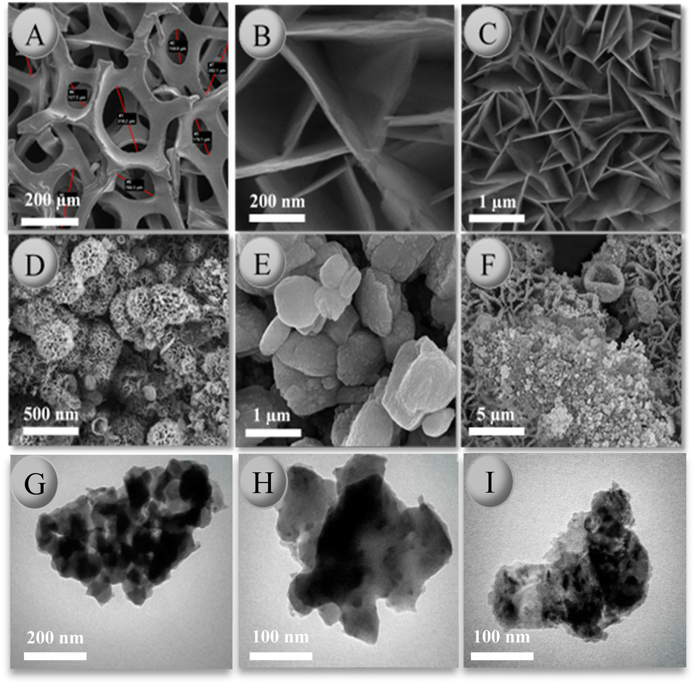 | ||
| Fig. 3 FE-SEM images of: (A) nickel foam (B and C) NiCo2O4 nanoflakes grown on NF (NiCo2O4/NF), (D–F) NiFeSe2 nanoparticles grown on NiCo2O4/NF (NiFeSe2/NiCo2O4/NF), and (G–I) TEM images of NiFeSe2 nanoparticles grown on NiCo2O4/NF (NiFeSe2/NiCo2O4/NF). | ||
According to Fig. 3B and C, the synthesized NiCo2O4 displays nanoflake morphology with a dimension of about 10–20 nm thick and 400–500 nm long. Moreover, as shown, the surface of the NF is homogeneously covered with NiCo2O4 nanoflakes. High magnification of NiCo2O4 nanosheets shows that the nanosheets are interconnected to each other. This feature not only offers a large number of active sites but also increases the charge transfer, which speeds up the kinetics of the reaction. Fig. 3D and E demonstrate the morphologies of NiFeSe2. They confirm the presence of NiFeSe2 nanoparticles attached to as-prepared NiCo2O4 nanoflakes on Ni-foam, resulting in the formation of the NiFeSe2/NiCo2O4/NF heterostructure. According to Fig. 3F, there is no noticeable change in the morphology of the as-prepared NiCo2O4 nanoflakes after synthesizing the second layer.
The TEM technique was employed for further characterization of the nanocomposite. Fig. 3G–I show the TEM images of NiFeSe2/NiCo2O4/NF. Combined with SEM, TEM results confirm that the NiFeSe2/NiCo2O4/NF is a heterostructure material comprising two phases, enhancing the transfer efficiency of charge carriers.
The EDX spectra of NiCo2O4/NF and NiFeSe2/NiCo2O4/NF are depicted in Fig. 4A and B, respectively. From these spectra, the presence of Ni, Co, and O elements in NiCo2O4/NF and Ni, Fe, Se, Co, and O elements in NiFeSe2/NiCo2O4/NF can be easily seen, which further confirms the successful preparation of the two materials. In addition, the distribution of elements was examined by EDX elemental mapping. As shown in Fig. 4A and B, elements are uniformly distributed in the as-prepared materials, indicating that no aggregation took place during the synthesis.
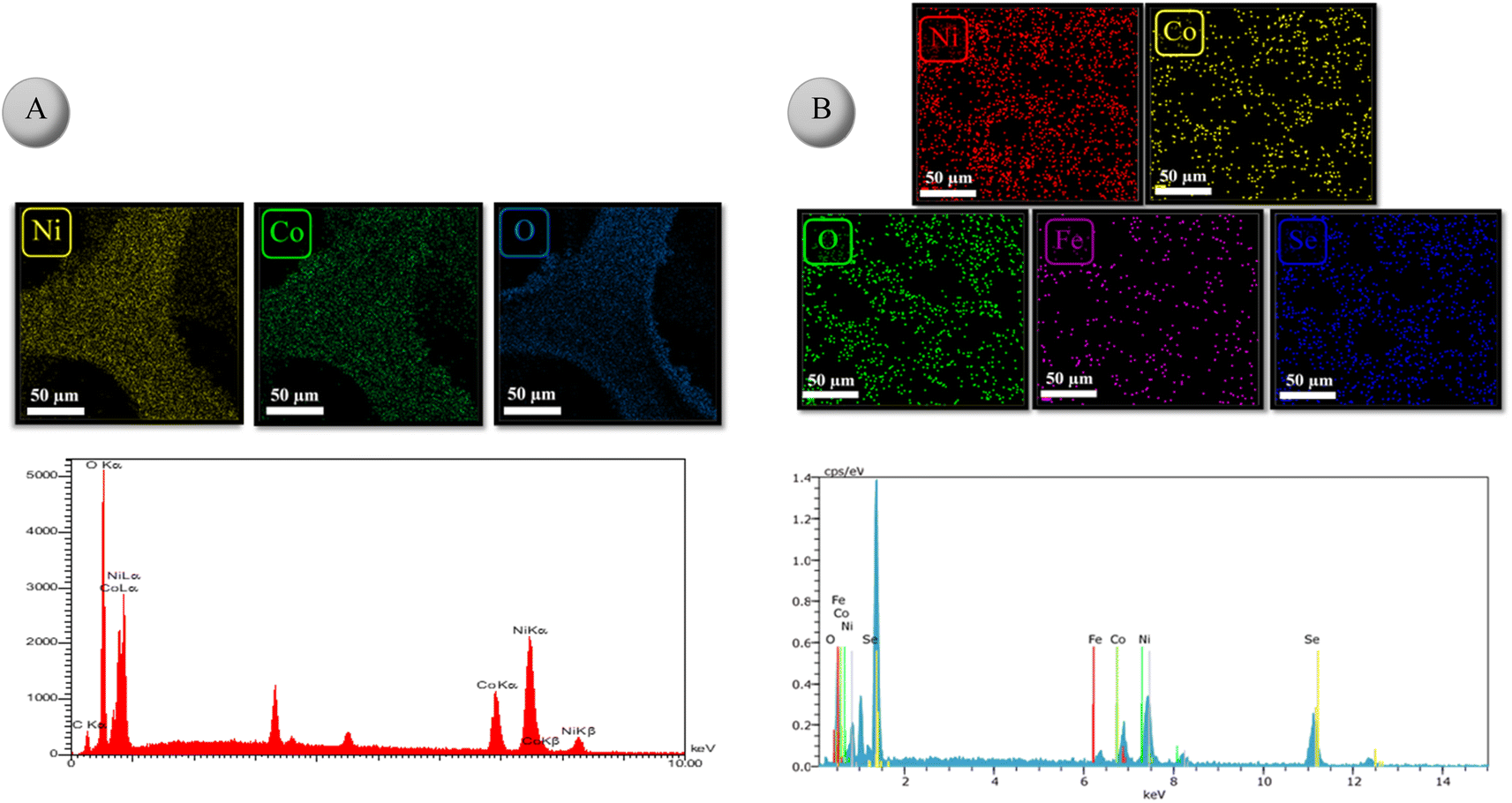 | ||
| Fig. 4 Elemental mapping images and the corresponding EDX spectrum of (A) NiCo2O4/NF and (B) NiFeSe2/NiCo2O4/NF. | ||
XPS analysis was carried out to examine the chemical composition and oxidation states of elements at the surface of the as-prepared NiFeSe2/NiCo2O4/NF. As shown in Fig. 5A, the characteristic peaks of Ni, Co, Fe, Se, O, and C are clearly observed in the survey spectrum. The much higher intensity of C and O peaks implies that these two elements came from sources besides the as-prepared material (most likely from the adventitious organics adsorbed to the surface). Fig. 5B– E show the high-resolution spectra of Se 3d, Fe 2p, Co 2p, and Ni 2p, respectively. As shown in Fig. 5B, the core levels at 54.6 and 55.4 eV in the Se 3d spectrum can be ascribed to Se 3d5/2 and Se 3d3/2, respectively.38 In addition, the broad peak at 65.0 eV is related to the oxidized selenium species (SeOx) formed at the surface of the sample.38 In Fig. 5C, the Fe 2p1/2 peak can be deconvoluted into two peaks at 702.1 and 706.7 eV, corresponding to Fe2+ and Fe3+, respectively.39,40 Moreover, the two peaks at 721.3 and 728.0 eV can be assigned to 2p3/2 transition of Fe2+ and Fe3+, respectively.39 As depicted in Fig. 5D, the Co 2p high-resolution spectrum consists of a spin–orbit doublet (2p1/2 and 2p3/2) and the corresponding shake-up satellites. Co 2p3/2 can be deconvoluted into two peaks at 780.5 and 779.5 eV, corresponding to Co2+ and Co3+, respectively.41 According to Fig. 5E, the peaks at 852.6 and 854.4 can be attributed to the 2p3/2 transition of Ni2+ and Ni3+, respectively.38 Furthermore, the peaks at 858.6 and 862.5 eV can be ascribed to Ni 2p3/2 and Ni 2p1/2 satellites, respectively.38
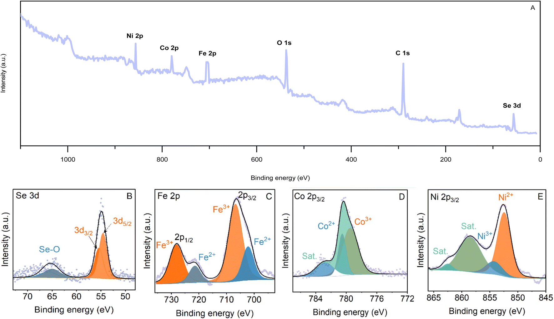 | ||
| Fig. 5 (A) XPS survey spectrum of NiFeSe2/NiCo2O4/NF, and high resolution XPS spectra of (B) Se 3d, (C) Fe 2p, (D) Co 2p, and (E) Ni 2p of NiFeSe2/NiCo2O4/NF. | ||
3.2. Electrocatalytic performance
The HER electrochemical performance of the synthesized materials was investigated by linear sweep voltammetry (LSV). The polarization curves were measured at a scan rate of 5 mV s−1 in 1.0 M KOH solution. The results are shown in Fig. 6A. As illustrated, NiFeSe2/NiCo2O4/NF shows the best catalytic performance among all the synthesized electrocatalysts. First, much higher current densities can be achieved by NiFeSe2/NiCo2O4/NF at the same overpotentials. Second, to reach the current density of 10 mA cm−2 NiFeSe2/NiCo2O4/NF required an overpotential (η) of only 83 mV, which is smaller than those of NiCo2O4/NF (η = 152 mV), NiFeSe2/NF (η = 163 mV) and NiFe/NiCo2O4/NF (η = 132 mV), as well as some of the reported state-of-the-art noble metal-free electrocatalysts such as NiCoSe2/CC (η = 112.7 mV),42 NiCo2S4/Ni3S2/NF (η = 119 mV),43 reduced NiCo2O4 (η = 135 mV),44 and NiFe/NiCo2O4/NF (η = 105 mV) (Fig. 7).45 Remarkably, the HER performance of NiFeSe2/NiCo2O4/NF is comparable to that of the benchmark Pt/C catalyst (η = 62 mV). For comparison, the activity of bare NF was also measured (η = 198 mV), which was lower than that of all the synthesized materials. It is hypothesized that the excellent HER performance of NiFeSe2/NiCo2O4/NF resulted from the synergistic effect of each component.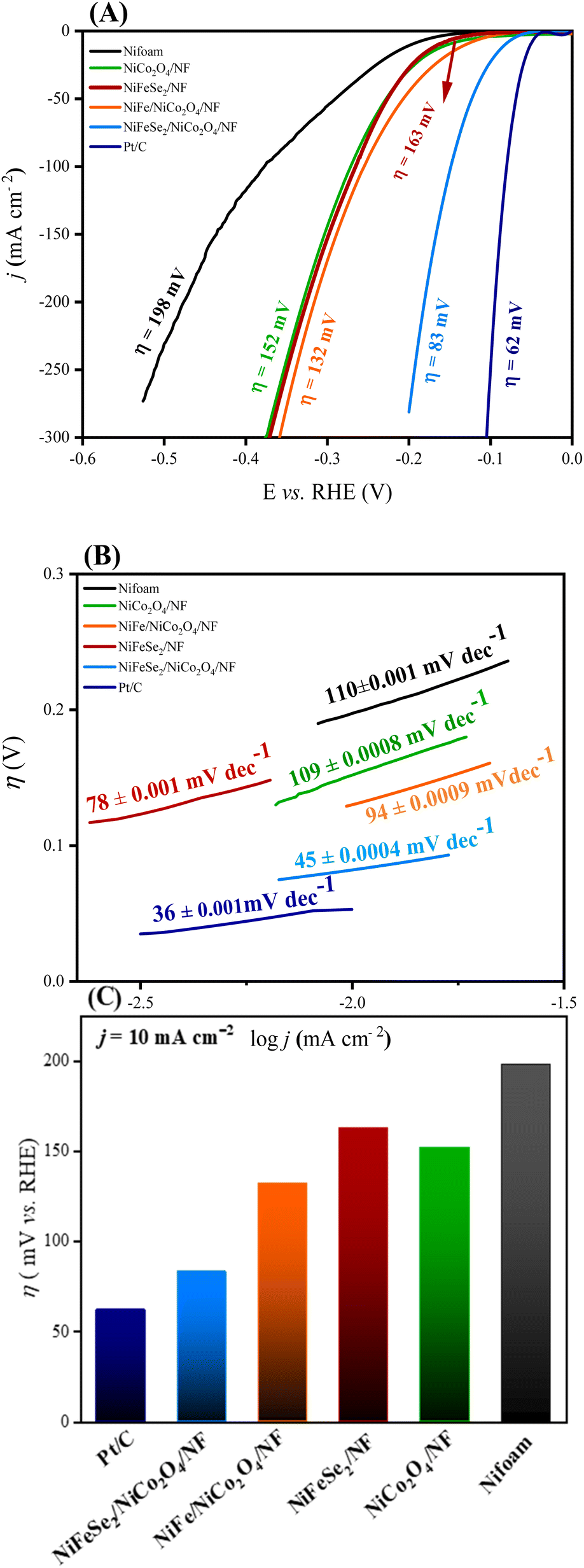 | ||
| Fig. 6 (A) Polarization curves of Pt/C, NiFeSe2/NiCo2O4/NF, NiFe/NiCo2O4/NF, NiFeSe2/NF, NiCo2O4/NF, and Ni-foam. (B) The corresponding Tafel plots. (C) The bar chart of overpotentials of catalysts measured at a current density of 10 mA cm−2. | ||
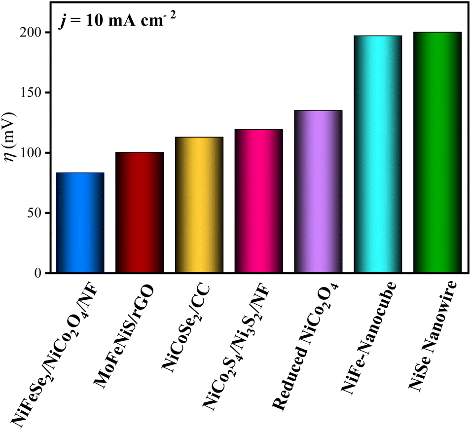 | ||
| Fig. 7 Comparison of hydrogen evolution reaction (HER) catalysts tested in alkaline media at a current density of 10 mA cm−2. | ||
To further explore the mechanism of the electrocatalytic HER, Tafel slopes were determined (from the linear region of the η vs. log![[thin space (1/6-em)]](https://www.rsc.org/images/entities/char_2009.gif) j plot, where j is the current density) for the prepared electrocatalysts. Fig. 6B shows the Tafel slopes of NiFeSe2/NiCo2O4/NF, NiFeSe2/NF, and NiCo2O4/NF samples. The much lower Tafel slope of NiFeSe2/NiCo2O4/NF compared to the other materials indicates the faster kinetics of the HER for this electrocatalyst. Moreover, the value of this Tafel slope (45 mV dec−1) suggests that the reaction proceeds via the Volmer–Tafel mechanism with a Tafel rate-determining step.46–48
j plot, where j is the current density) for the prepared electrocatalysts. Fig. 6B shows the Tafel slopes of NiFeSe2/NiCo2O4/NF, NiFeSe2/NF, and NiCo2O4/NF samples. The much lower Tafel slope of NiFeSe2/NiCo2O4/NF compared to the other materials indicates the faster kinetics of the HER for this electrocatalyst. Moreover, the value of this Tafel slope (45 mV dec−1) suggests that the reaction proceeds via the Volmer–Tafel mechanism with a Tafel rate-determining step.46–48
To evaluate the electrochemical surface area (ECSA) of the synthesized electrocatalysts, cyclic voltammetry (CV) was performed at different scan rates in the non-faradaic potential window (Fig. 8A–C). From the slope of the linear fit to the plot of Δj vs. scan rate (where Δj is half of the difference between the current densities of the forward and reverse sweeps at the middle of the potential window), the double-layer capacitance (Cdl) can be calculated. According to Fig. 8D, the obtained value for the Cdl of NiFeSe2/NiCo2O4/NF is 9.45 mF cm−2, which is higher than that of NiCo2O4/NF (2.30 mF cm−2) and bare NF (0.65 mF cm−2), respectively. The observed trend in Cdl's implies that the formation of the NiFeSe2 layer on the top of the NiCo2O4 layer has dramatically increased the active surface area of the catalyst. The considerably high value of Cdl implies that the catalyst has a high electrochemically active surface area.43,49,50
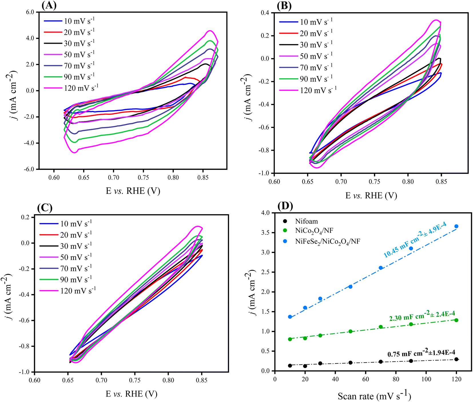 | ||
| Fig. 8 CV curves of: (A) NiFeSe2/NiCo2O4/NF, (B) NiCo2O4/NF, and (C) NF recorded in 1.0 M KOH in the non-faradaic region of 0.60–0.90 V vs. RHE at the scan rates of 10, 20, 30, 50, 70, 90, and 120 mV s−1. (D) Capacitive current density. Scan rate for NiFeSe2/NiCo2O4/NF, NiCo2O4/NF and NF. The corresponding specific capacitances were obtained from the slope of linear fits (dashed lines) to the data. | ||
The stability of an electrocatalyst is a crucially important factor for its practical applications. The long-term stability of NiFeSe2/NiCo2O4/NF was investigated by chronoamperometry and CV. As shown in Fig. 9A, the electrocatalyst maintained the current density of 20 mA cm−2 (measured at the fixed potential of 0.095 V vs. RHE) for over 8 h with no noticeable drop in a 1 M KOH solution. Also, Fig. 9B shows that after running 700 consecutive CV cycles at a scan rate of 50 mV s−1, there is only a slight loss (about 7%) in the current density of NiFeSe2/NiCo2O4/NF in the faradaic region. The long-term stability and durability of the electrocatalyst can be related to its free design and indicate the robust bonding between the layers.51
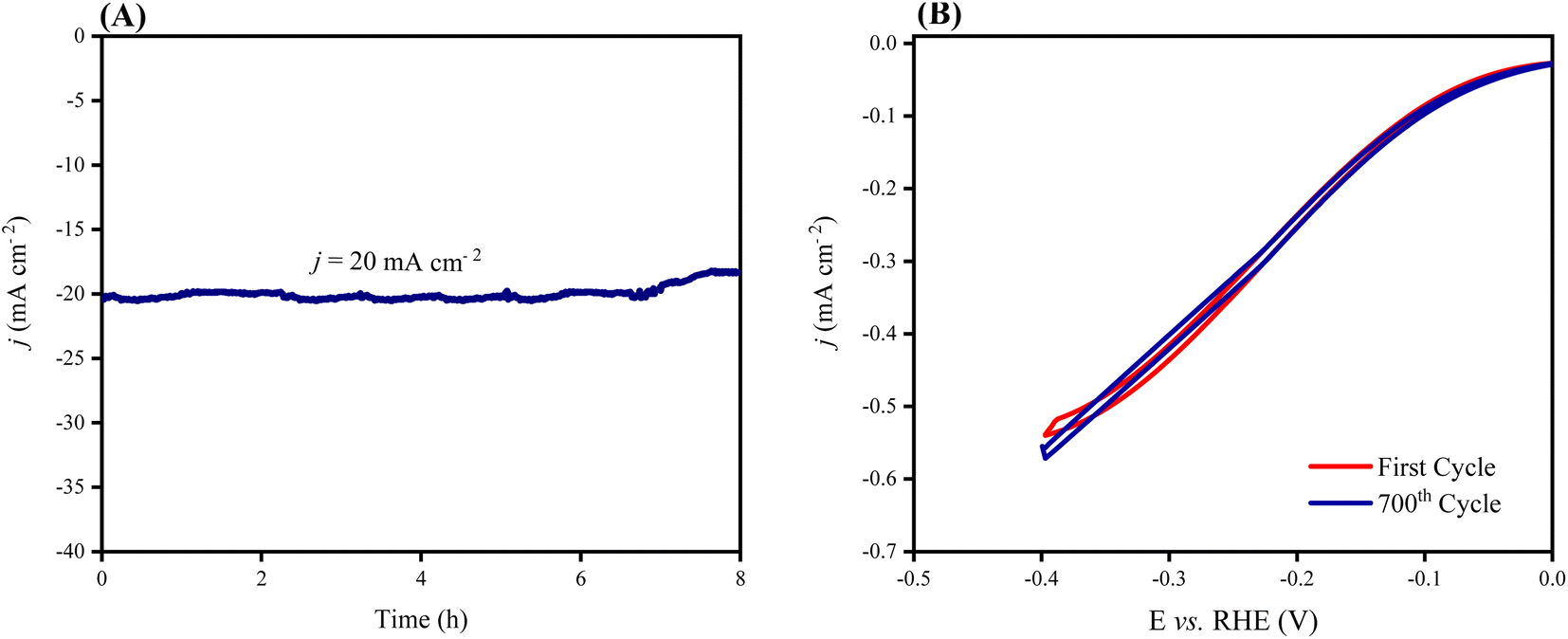 | ||
| Fig. 9 (A) The chronoamperometry curve for the NiFeSe2/NiCo2O4/NF electrode measured at the constant potential of 0.095 V (vs. RHE) in 1 M KOH electrolyte. (B) CV curves of the NiFeSe2/NiCo2O4/NF electrode corresponding to the first (red) and 700th (blue) cycles, obtained in 1 M KOH electrolyte in the potential window of −0.4–0.0 V (vs. RHE). | ||
As depicted in Fig. 10, the as-prepared electrocatalyst exhibited a very high faradaic efficiency of 99.5%, implying an almost complete conversion of electricity to hydrogen gas.52,53
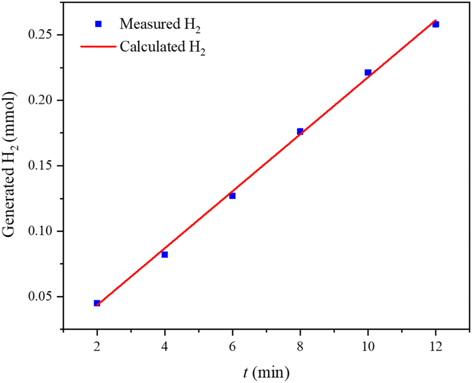 | ||
| Fig. 10 The amount of theoretically calculated (red line) and experimentally measured (line with dots) hydrogen versus time for NiFeSe2/NiCo2O4/NF at a constant current of −70 mA. | ||
To gain further insight into the kinetics of charge transfer at the electrode/electrolyte interface, electrochemical impedance spectroscopy (EIS) was employed. EIS measurements were performed in the frequency range of 0.1–105 Hz at a potential of −0.15 V vs. RHE with an AC amplitude of 4 mV. The Nyquist plots are depicted in Fig. 11 and consist of two distinct features: (1) a semicircle in the high-frequency region; (2) a straight line in the low-frequency region. These plots can be well fitted by the Randles equivalent circuit54–56 given in the inset of Fig. 11. The diameter of the semicircle represents the resistance to the interfacial charge transfer (Rct), while its intersection with the horizontal axis (Z′) at high frequencies (left side) corresponds to solution resistance (Rs).
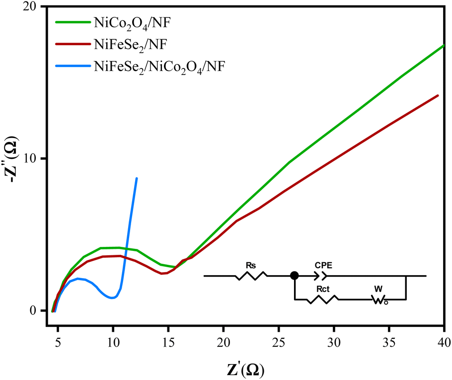 | ||
| Fig. 11 Nyquist plots of NiFeSe2/NiCo2O4/NF, NiCo2O4/NF, and NiFeSe2/NF electrodes in 1 M KOH in the frequency range of 0.1 Hz to 100 kHz. The inset is the equivalent circuit diagram. | ||
According to Fig. 11, the solution resistance is about 4.5 Ω consistent with the value obtained with the positive feedback method. Furthermore, Rct values obtained for NiFeSe2/NiCo2O4/NF, NiCo2O4/NF, and NiFeSe2/NF are 4.3, 10.5, and 10.4 Ω, respectively. The smaller value of Rct for NiFeSe2/NiCo2O4/NF implies faster kinetics of charge transfer. Also, by comparing the slope of the linear line at the low-frequency region, it can be concluded that the mass transfer resistance in NiFeSe2/NiCo2O4/NF is lower than that of the pristine NiCo2O4/NF and NiFeSe2/NF. This information confirms the superior electrochemical performance of NiFeSe2/NiCo2O4/NF.
By comparing the Nyquist plots and fitted parameters of the corresponding equivalent circuit (inset of Fig. 11) of the three materials, no evidence of resistance for each layer and roots in the changing of the charge transfer mechanism was observed. This shows that the composite is acting as an accreting single-phase material. The interfaces not only limited the kinetics of charge transfer but also enhanced the electron transfer due to the synergistic effect. CPE is the constant phase element that appears because of the rough surface or distribution of reaction rates. The obtained CPE value of NiFeSe2/NiCo2O4/NF is greater than those of NiCo2O4/NF and NiFeSe2/NF, which confirms that the electroactive surface area of NiFeSe2/NiCo2O4/NF is greater than that of others which agrees with the previously reported ECSA data.
4 Conclusions
In summary, several hierarchical nanostructures have been successfully synthesized on NF by a hydrothermal method. The multilayer, NiFeSe2/NiCo2O4/NF electrocatalyst exhibits remarkable HER performance in 1 M KOH, with a low overpotential of 83 mV (measured at a current density of 10 mA cm−2), a small Tafel slope of 45 mV dec−1, and a high current density of 270 mA cm−2 at −0.2 V (vs. RHE). Moreover, NiFeSe2/NiCo2O4/NF shows excellent long-term electrochemical stability and durability. Compared to the catalysts reported in the published literature so far in alkaline media, including the benchmark precious-metal-based catalysts and state-of-the-art nonprecious metal-based catalysts, the obtained electrode architecture exhibits exceptional catalytic activity towards the HER. The superior HER performance of NiFeSe2/NiCo2O4/NF compared to the other prepared materials can be attributed to its improved electrochemical surface area (ECSA) and charge transfer kinetics, resulting from the synergistic effects between the components of the catalyst. These findings suggest that NiFeSe2/NiCo2O4/NF can be employed as an efficient electrocatalyst for the HER.Author contributions
The manuscript was written through the contributions of all authors.Conflicts of interest
There are no conflicts to declare.Acknowledgements
The authors would like to thank the Research Council of Shahid Beheshti University for financial support.References
- J. Wang, X. Yue, Y. Yang, S. Sirisomboonchai, P. Wang, X. Ma, A. Abudula and G. Guan, J. Alloys Compd., 2020, 819, 153346 CrossRef CAS.
- X. Zou and Y. Zhang, Chem. Soc. Rev., 2015, 44, 5148–5180 RSC.
- W. Yang and S. Chen, Chem. Eng. J., 2020, 393, 124726 CrossRef CAS.
- J. Huang, W. Hong, J. Li, B. Wang and W. Liu, Sustainable Energy Fuels, 2020, 4, 1078–1083 RSC.
- R. Yukesh Kannah, S. Kavitha, O. Parthiba Karthikeyan, E. R. Rene, G. Kumar and J. Rajesh Banu, Bioresour. Technol., 2021, 332, 125055 CrossRef CAS PubMed.
- M. S. Dresselhaus and I. L. Thomas, Nature, 2001, 414(6861), 332–337 CrossRef CAS.
- J. D. Holladay, J. Hu, D. L. King and Y. Wang, Catal. Today, 2009, 139, 244–260 CrossRef CAS.
- M. Gong, D. Y. Wang, C. C. Chen, B. J. Hwang and H. Dai, Nano Res., 2015, 9(1), 28–46 CrossRef.
- D. Taherinia, S. H. Moravvej, M. Moazzeni and E. Akbarzadeh, Sustainable Energy Fuels, 2021, 5, 2994–3000 RSC.
- S. Kumaravel, K. Karthick, S. S. Sankar, A. Karmakar, R. Madhu, K. Bera and S. Kundu, Sustainable Energy Fuels, 2021, 5, 6215–6268 RSC.
- W. Yang, Z. Wang, W. Zhang and S. Guo, Trends Chem., 2019, 1, 259–271 CrossRef CAS.
- X. Wang, Y. Zheng, W. Sheng, Z. J. Xu, M. Jaroniec and S. Z. Qiao, Mater. Today, 2020, 36, 125–138 CrossRef CAS.
- S. Bargozideh, M. Tasviri, S. Shekarabi and H. Daneshgar, New J. Chem., 2020, 44, 13083–13092 RSC.
- S. Anantharaj, S. R. Ede, K. Karthick, S. Sam Sankar, K. Sangeetha, P. E. Karthik and S. Kundu, Energy Environ. Sci., 2018, 11, 744–771 RSC.
- M. Chhowalla, H. S. Shin, G. Eda, L. J. Li, K. P. Loh and H. Zhang, Nat. Chem., 2013, 5(4), 263–275 CrossRef PubMed.
- F. Zhang, R. Ji, Y. Liu, Y. Pan, B. Cai, Z. Li, Z. Liu, S. Lu, Y. Wang, H. Jin, C. Ma and X. Wu, Appl. Catal., B, 2020, 276, 119141 CrossRef CAS.
- H. Zhou, Y. Liu, L. Zhang, H. Li, H. Liu and W. Li, J. Colloid Interface Sci., 2019, 533, 287–296 CrossRef CAS.
- M. A. Zarepour and M. Tasviri, J. Photochem. Photobiol., A, 2019, 371, 166–172 CrossRef CAS.
- C. Li, X. Han, F. Cheng, Y. Hu, C. Chen and J. Chen, Nat. Commun., 2015, 6(1), 1–8 CAS.
- C. Goswami, K. K. Hazarika and P. Bharali, Mater. Sci. Energy Technol., 2018, 1, 117–128 Search PubMed.
- X. Du, C. Zhang, H. Wang, Y. Wang and X. Zhang, J. Alloys Compd., 2021, 885, 160972 CrossRef CAS.
- Y. Zhang, M. Yang, X. Jiang, W. Lu and Y. Xing, J. Alloys Compd., 2020, 818, 153345 CrossRef CAS.
- K. Patil, P. Babar, D. M. Lee, V. Karade, E. Jo, S. Korade and J. H. Kim, Sustainable Energy Fuels, 2020, 4, 5254–5263 RSC.
- C. Zeng, L. Dai, Y. Jin, J. Liu, Q. Zhang and H. Wang, Sustainable Energy Fuels, 2021, 5(5), 1347–1365 RSC.
- Y. Zhu, Q. Lin, Y. Zhong, H. A. Tahini, Z. Shao and H. Wang, Energy Environ. Sci., 2020, 13, 3361–3392 RSC.
- Y. Gong, Z. Yang, Y. Lin, J. Wang, H. Pan and Z. Xu, J. Mater. Chem. A, 2018, 6, 16950–16958 RSC.
- S. Chen, D. Huang, D. Liu, H. Sun, W. Yan, J. Wang, M. Dong, X. Tong and W. Fan, Appl. Catal., B, 2021, 291, 120065 CrossRef CAS.
- F. Shen, Y. Wang, G. Qian, W. Chen, W. Jiang, L. Luo and S. Yin, Appl. Catal., B, 2020, 278, 119327 CrossRef CAS.
- R. Smith, C. Pasquini, S. Loos and P. Chernev, Nat. Commun., 2017, 8(1), 1–8 CrossRef CAS PubMed.
- X. Lu and C. Zhao, Nat. Commun., 2015, 6(1), 1–7 Search PubMed.
- Z. Wang, J. Li, X. Tian, X. Wang, Y. Yu, K. A. Owusu, L. He and L. Mai, ACS Appl. Mater. Interfaces, 2016, 8, 19386–19392 CrossRef CAS.
- J. Hu, S. Zhu, Y. Liang, S. Wu, Z. Li, S. Luo and Z. Cui, J. Colloid Interface Sci., 2021, 587, 79–89 CrossRef CAS PubMed.
- R. Suarez Anzorena, F. F. Muñoz, P. Bonelli, A. L. Cukierman and S. A. Larrondo, Ceram. Int., 2020, 46, 11776–11785 CrossRef CAS.
- C. Jia, P. Yang and A. Zhang, Mater. Chem. Phys., 2014, 143, 794–800 CrossRef CAS.
- H. Hu, W. Xiao, J. Yuan, J. Shi, D. He and W. Shangguan, J. Sol-Gel Sci. Technol., 2008, 45, 1–8 CrossRef CAS.
- N. A. Karim, M. S. Alias and H. Yang, Catalysts, 2021, 11, 279 CrossRef CAS.
- C. Lamiel, V. H. Nguyen, I. Hussain and J. J. Shim, Energy, 2017, 140, 901–911 CrossRef CAS.
- L. Zhou, P. He, T. Yang, S. Chen, Q. He, F. Dong, L. Jia, H. Zhang, B. Jia and X. He, Int. J. Hydrogen Energy, 2020, 45, 28682–28695 CrossRef CAS.
- L. Lv, Z. Li, K. H. Xue, Y. Ruan, X. Ao, H. Wan, X. Miao, B. Zhang, J. Jiang, C. Wang and K. K. Ostrikov, Nano Energy, 2018, 47, 275–284 CrossRef CAS.
- Y. Zhao, Y. Gao, Z. Chen, Z. Li, T. Ma, Z. Wu and L. Wang, Appl. Catal., B, 2021, 297, 120395 CrossRef CAS.
- X. Dai, Y. Dai, J. Lu, L. Pu, W. Wang, J. Jin, F. Ma and N. Tie, Ionics, 2020, 26, 2501–2511 CrossRef CAS.
- J. Yu, Y. Tian, F. Zhou, M. Zhang, R. Chen, Q. Liu, J. Liu, C. Y. Xu and J. Wang, J. Mater. Chem. A, 2018, 6, 17353–17360 RSC.
- H. Liu, X. Ma, Y. Rao, Y. Liu, J. Liu, L. Wang and M. Wu, ACS Appl. Mater. Interfaces, 2018, 10, 10890–10897 CrossRef CAS.
- C. Xiao, Y. Li, X. Lu, C. Zhao, C. Xiao, Y. Li, X. Lu and C. Zhao, Adv. Funct. Mater., 2016, 26, 3515–3523 CrossRef CAS.
- C. Tang, N. Cheng, Z. Pu, W. Xing and X. Sun, Angew. Chem., 2015, 127, 9483–9487 CrossRef.
- Y. Yang, W. Zhang, Y. Xiao, Z. Shi, X. Cao, Y. Tang and Q. Gao, Appl. Catal., B, 2019, 242, 132–139 CrossRef CAS.
- F. Te Tsai, Y. T. Deng, C. W. Pao, J. L. Chen, J. F. Lee, K. T. Lai and W. F. Liaw, J. Mater. Chem. A, 2020, 8, 9939–9950 RSC.
- Q. Che, Q. Li, X. Chen, Y. Tan and X. Xu, Appl. Catal., B, 2020, 263, 118338 CrossRef CAS.
- S. Peng, F. Gong, L. Li, D. Yu, D. Ji, T. Zhang, Z. Hu, Z. Zhang, S. Chou, Y. Du and S. Ramakrishna, J. Am. Chem. Soc., 2018, 140, 13644–13653 CrossRef CAS PubMed.
- M. Scohy, S. Abbou, V. Martin, B. Gilles, E. Sibert, L. Dubau and F. Maillard, ACS Catal., 2019, 9, 9859–9869 CrossRef CAS.
- D. Wang, Q. Li, C. Han, Z. Xing and X. Yang, Appl. Catal., B, 2019, 249, 91–97 CrossRef CAS.
- M. Wang, S. Liu, T. Qian, J. Liu, J. Zhou, H. Ji, J. Xiong, J. Zhong and C. Yan, Nat. Commun., 2019, 10, 1–8 CrossRef.
- B. Yodwong, D. Guilbert, M. Phattanasak, W. Kaewmanee, M. Hinaje and G. Vitale, Energies, 2020, 13, 4792 CrossRef CAS.
- F. Luo, L. Guo, Y. Xie, J. Xu, K. Qu and Z. Yang, Appl. Catal., B, 2020, 279, 119394 CrossRef CAS.
- J. Wang, X. Yue, Y. Yang, S. Sirisomboonchai, P. Wang, X. Ma, A. Abudula and G. Guan, J. Alloys Compd., 2020, 819, 153346 CrossRef CAS.
- D. Loveday, P. Peterson and B. Rodgers, Evaluation of organic coatings with electrochemical impedance spectroscopy, J. Coat. Technol., 2004, 8, 46 Search PubMed.
Footnote |
| † Electronic supplementary information (ESI) available. See DOI: https://doi.org/10.1039/d2se01196d |
| This journal is © The Royal Society of Chemistry 2023 |