
 Open Access Article
 This Open Access Article is licensed under a Creative Commons Attribution-Non Commercial 3.0 Unported Licence
A cork based substrate coupled with artificial antibodies for point-of-care detection of pro-inflammatory cytokine biomarkers†
Bárbara
Correia
a,
Daniela
Oliveira
a,
Georgeta
Vulpe
b,
Ana P. M.
Tavares
c,
M. Goreti F.
Sales
 c,
Abel J.
Duarte
de,
Sanjiv
Sharma
*b and
Felismina T. C.
Moreira
*a
c,
Abel J.
Duarte
de,
Sanjiv
Sharma
*b and
Felismina T. C.
Moreira
*a
aBioMark@ISEP-CEB/LABBELS, School of Engineering, Polytechnic of Porto, R. Dr. António Bernardino de Almeida, 431, 4249-015 Porto, Portugal. E-mail: ftm@isep.ipp.pt
bDepartment of Biomedical Engineering, Faculty of Science and Engineering, Swansea University, Swansea SA1 8EN, UK. E-mail: sanjiv.sharma@swansea.ac.uk
cBioMark@UC-CEB/LABBELS, Faculty of Sciences and Technology, University of Coimbra, R. Sílvio Lima, Pólo II, 3030-790 Coimbra, Portugal
dREQUIMTE, School of Engineering, Polytechnic of Porto, Porto, R. Dr. António Bernardino de Almeida, 431, 4249-015 Porto, Portugal
eICETA, School of Engineering, Polytechnic of Porto, Porto, R. Dr. António Bernardino de Almeida, 431, 4249-015 Porto, Portugal
First published on 9th May 2023
Abstract
Whilst single use point of care testing (PoCT) devices have transformed healthcare globally, there are major concerns over their environmental consequences. These concerns could be addressed by employing devices made of environmentally friendly materials. Herein, we report on the use of cork based PoCT devices. Cork is known to be fully biodegradable and can be easily recycled without producing toxic residues. We report on how a cork-based substrate coupled with a molecularly imprinted polymer (MIP) that serves as an “artificial antibody” can be used for point-of-care testing of the pro-inflammatory biomarker interleukin 6 (IL-6). The featured PoCT device has an electrochemical transducer that provides the desired clinical dynamic range for blood and can measure concentrations as low as 1 pg mL−1, indicating its usefulness in point of care measurements for monitoring pathological disorders, worldwide. In addition, it has a huge environmental impact as it can reduce the waste generated by other polymeric/ceramic carriers used for the same purpose.
1. Introduction
The COVID-19 pandemic has led to an increased usage and demand for single use, disposable devices in the form of personal protective equipment and test-based lateral flow, intensifying pressure on an existing out-of-control problem of microplastic pollution.1 More than eight million tons of pandemic-associated plastic waste have been generated globally, with more than 25![[thin space (1/6-em)]](https://www.rsc.org/images/entities/char_2009.gif) 000 tons entering the global ocean. One of the main contributors to this problem was the use of rapid point-of-care testing (PoCT) diagnostic kits, to monitor and control the transmission of the virus between humans.
000 tons entering the global ocean. One of the main contributors to this problem was the use of rapid point-of-care testing (PoCT) diagnostic kits, to monitor and control the transmission of the virus between humans.
Although PoCT diagnostics play a vital role in both developed and developing countries, they employ substrates primarily based on affordability and mass production capability. The choice of synthetic substrates is based on their enhanced physicochemical properties, potential for personalised health monitoring, and ability to be customized for PoC diagnostics of cytokine biomarkers.2,3 The material selection criteria include looking at the environment aspect. This includes looking at the impact of materials and processing, the amount of waste generated, future legislation and the perception towards synthetic materials. It is therefore imperative to engineer sustainable healthcare devices based on natural, environmentally friendly materials.4
Electrochemical biosensors have attracted much attention due to their simplicity, suitability, low cost, and sensitivity in PoCT applications.5 Several (bio)recognition elements have been used in sensing devices for the recognition of different analytes. Some rely on natural antibodies,6–10 others on synthetic reagents such as aptamers11–13 or molecularly imprinted polymers (MIPs), also known as artificial antibodies. The use of MIPs as bioreceptors has become a powerful tool in the field of biosensors due to its advantages in terms of pH and temperature robustness, reusability, low cost, and stability.14 They are fabricated in the presence of a target molecule, followed by the removal step of the imprinted target molecule to produce biomimetic cavities with a complementary shape that allows efficient and selective recognition of structural features of small organic molecules and even large molecules such as proteins, viruses and bacteria.14
Electrochemical PoCT devices employing MIP technology have shown to be promising alternatives to immunosensors. Several research papers have been described in the literature to use MIP-based materials as a biological sensing layer for the detection of inflammatory biomarkers. IL-6 biosensors based on printing MIPs such as electropolymerised pyrrole,15 carboxylated pyrrole16 and polydopamine17 employing nanomaterial systems such as graphene, carbon nanotubes, metal-based nanoparticles and other adapters in commercial electrodes have been reported for the relevant clinical range (1–200 pg mL−1) with a limit of detection below 1 pg mL−1.
We report here cork-based carbon printed electrodes imprinted with artificial antibodies for the monitoring of cytokine biomarker IL-6. The replacement of plastic with cork is due to it being a natural, environmentally friendly material. Moreover, it biodegrades completely and can be easily recycled without producing toxic residues. “Artificial antibodies” employed as bioreceptors can be mass produced and therefore vital in manufacturing low cost PoCT devices. Owing to their enhanced physical and chemical properties, as well as affordability and amenity to mass production, this combination of cork and artificial antibodies has been employed to develop next-generation PoCT diagnostic devices with enhanced performances.
Herein, we demonstrate the capability of this combination towards developing PoC devices for a plethora of clinical applications involving real time monitoring of cytokines. Overexpression of interleukin 6 (IL-6) biomarkers can be found not only in blood but also in saliva18 and skin interstitial fluid (ISF).19,20 They are implicated in various medical conditions such as inflammatory diseases, infections, and different types of cancer including lung, colorectal, prostate, and breast cancers.
2. Experimental
2.1 Materials and methods
:1 (monomer/template). Polymerization was achieved by cyclic voltammetry (CV), between −0.2 V and +1.0 V, at a scan rate of 0.02 V s−1, for 15 cycles. The IL-6 protein was removed from the polymer matrix by incubating 0.5 M sulphuric acid solution on the working electrode for 1 hour at room temperature. It was then washed extensively with ultrapure water to remove the unreacted monomers and remove all IL-6 from the polymer matrix. In parallel, a non-imprinted polymer (NIP) was prepared. This material was prepared in a similar way to that described for the MIP, excluding, however, the template molecule from the procedure with replacement by the same volume of PBS, pH 7.4.
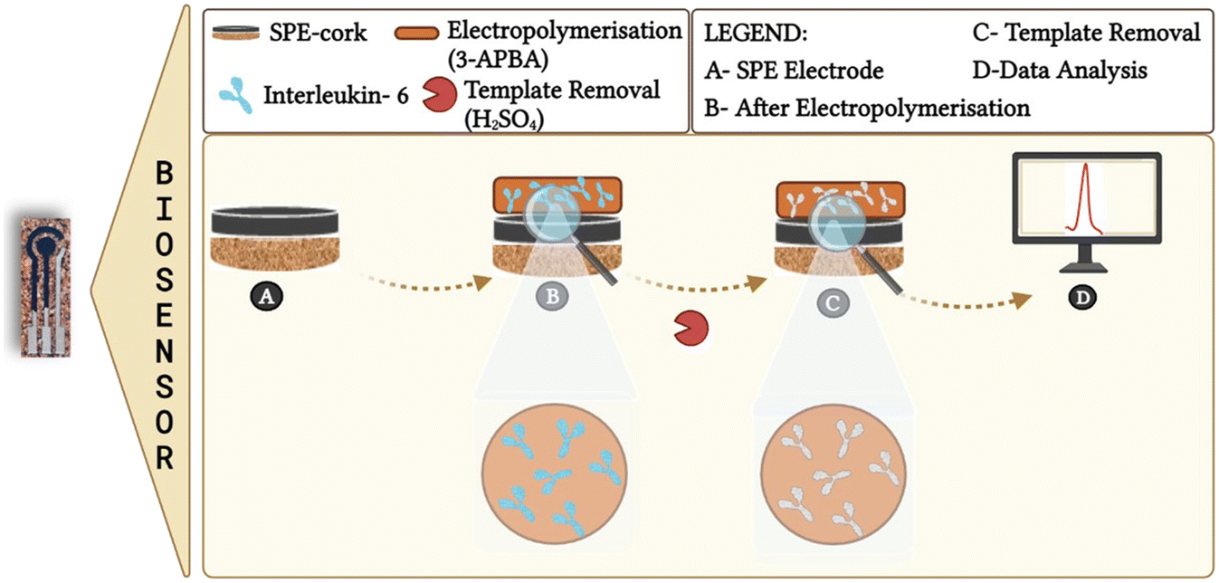 | ||
| Fig. 1 Schematic of the construction of the MIP sensing device. | ||
All IL-6 standard solutions were prepared in a PBS buffer solution (pH 5). In accordance with the isoelectric point (PI) of IL-6, which has a value of 6.17,16 the buffer solution used was more acidic to promote a solution with positive charges due to the protonation of the amines present in the analyte and protonation of some acidic groups that are no longer negatively charged at this pH. Since the physiological value of IL-6 in a sample from a normal patient is 1.6 ± 0.8 pg mL−1, 5 solutions were defined with standards of 1 pg mL−1 to 10000 pg ml−1. These assays were repeated in a more realistic context, preparing standard solutions of IL-6 in Cormay serum, diluted one thousand-fold in PBS buffer (pH 5). Selectivity studies were performed against different solutions comprising of a fixed concentration of IL-6 (100 pg mL−1) but varying concentrations of glucose (0.7 mg mL−1), urea (0.2 mg mL−1) and BSA (1 mg mL−1) diluted in pH 5.0. Incubation was at room temperature for 20 minutes. The respective interfering substances were prepared in a buffer with pH 5.
3. Results and discussion
3.1 Surface characterisation
The monomer used here has several advantages, including easy control of polymer thickness due to self-limiting growth and a simple regeneration process after use.23 Furthermore, since IL-6 is a glycosylated cytokine, it is compatible with the boronic acid functional group in 3-APBA. This is advantageous because boronic acid can covalently react with cis-diols to form five- or six-membered cyclic esters in an alkaline aqueous solution, which dissociate when the medium changes to an acidic pH. This remarkable chemistry makes boronic acids interesting ligands for numerous applications in sensing, separation, and self-assembly.24
In general, the CV data obtained after MIP and NIP polymerization are consistent with the formation of an insulating layer after the 15 cycles of electropolymerisation at a scan rate of 0.02 V s−1. For both materials, the MIP and NIP, there was a significant decrease in the current flow as a function of applied potential. In Fig. S2-A1 and S2-A2,† a decrease in the current and consequently a significant decrease in the height of the oxidation/reduction peaks was observed for both electrodes (C-SPE and cork) compared to the bare carbon electrodes. In addition, the decrease in current was more pronounced for the cork–SPE.
The EIS measurements support the data from CV (Fig. S2 – B1 and B2†). After the electropolymerisation of 3-APBA, an increase in charge transfer resistance (Rct) from 1000 Ω to about 5000 Ω was observed. As can be seen in Fig. S2 – B1 and B2,† the Rct of the MIP sensor is higher than that of the NIP, which is built on commercial electrodes. This behaviour is expected when the protein causes an increase in Rct due to its high molecular weight. However, an opposite behaviour was observed for the sensors fabricated on the cork–SPE. This behaviour was not expected since all steps are similar, and the only difference is the composition of the support material and the composition of the carbon ink. A possible explanation for this event is that the composition of the ink changes the structure of the film formed on the surface of the electrodes.
The final step of the imprinting process is the removal of the template from the polymer matrix. In this work, sulfuric acid was used as a release agent.25 Fig. S2† shows the CVs and EIS results after template removal, and a higher effect was observed with cork–SPE (A2 and B2). Therefore, a slight increase in the current was observed for the CV technique, which was higher for the MIP built on cork–SPE, with well-defined oxidation and reduction peaks. A plausible explanation is that the protein was removed from the polymeric matrix, and it could cause some cavities in the polymer, which facilitates the electron transfer in the interface solution/electrode. The impedimetric tests agree with the CV data, with a decrease in the impedance value compared to the electropolymerisation step. Thus, the results are consistent with the expectations. For both NIP and MIP, there was a change in the response when the sulfuric acid chemically changed the electrode surface. The difference between the removal step and the polymerization step was more pronounced for the MIPs.
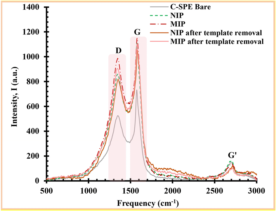 | ||
| Fig. 2 Raman spectra of the different immobilization stages of the biosensor. | ||
The peaks are related to the hybridization of carbon atoms. The G peak represents the bonding vibrations of the sp2 hybridization carbon atoms, indicating the C![[double bond, length as m-dash]](https://www.rsc.org/images/entities/char_e001.gif) C stretching, while the D peak expresses the sp3 hybridization, indicating the defects in the carbon caused by chemical modification. Therefore, the intensity ratio between the D peak and the G peak is usually used to confirm the presence of a particular chemical modification in the carbon material.
C stretching, while the D peak expresses the sp3 hybridization, indicating the defects in the carbon caused by chemical modification. Therefore, the intensity ratio between the D peak and the G peak is usually used to confirm the presence of a particular chemical modification in the carbon material.
The bare C-SPE exhibits an ID/IG ratio of 0.72. After the electropolymerisation of the MIP on it, an increase to 0.86 was observed, indicating that the carbon material was modified. The intensity ratio of the MIP was higher than that of the NIP, where it was 0.77, indicating that the difference in values was due to the presence of protein in the polymer matrix. Considering the results of the IL-6 removal step, where the ratio ID/IG decreased from 0.86 to 0.82, this suggests that the protein was successfully extracted from the polymer matrix. Moreover, the NIP was subjected to the same conditions as the MIP during the template removal process and showed almost no chemical change on its surface (ID/IG ratio of 0.78). This fact confirms the successful removal of the protein from the MIP assembly, while also confirming that the polymer network was unaffected by this removal stage. Overall, the Raman spectra confirmed the successful chemical change at each step associated with the assembly of the MIP on the bare C-SPE surface.
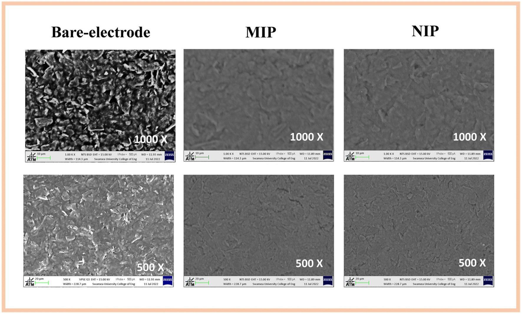 | ||
| Fig. 3 SEM analysis for the C-SPE, MIP and NIP materials. | ||
3.2 Analytical response of the electrochemical biosensors
The analytical response of the MIP and NIP sensors was evaluated after optimizing the assembly parameters such as monomer concentration and pH. The calibration curve was generated by incubating different standards of protein IL-6 on the electrode surface. Solutions with increasing IL-6 concentrations from 1 pg ml−1 to 10000 pg ml−1 prepared in a buffer solution (PBS) with a pH of 5 were incubated for 20 min at 7 μl on the working electrode. After washing the electrode with ultrapure water, the electrochemical response between the different protein concentrations was then recorded for each sensor using a redox probe solution. This procedure was performed in parallel with the material NIP. The typical charge transfer resistance (RCT) data obtained for the MIP (A) and NIP (B) are shown in Fig. 4 for commercial electrodes. The electrochemical signal was then plotted against the IL-6 concentration. The calibration curves were evaluated for the sensors (the commercial and homemade cork electrodes).
 | ||
| Fig. 4 EIS spectra of the MIP and NIP sensors on commercial C-SPE and cork–SPE biosensors. MIP and NIP materials on commercial electrodes (A1 and B1); MIP and NIP materials on homemade cork electrodes (A2 and B2). The measurements were performed in 5 mM K3[Fe(CN)6] and K4[Fe(CN)6] and prepared in 0.1 M KCl. | ||
Fig. 4 shows that the MIP and NIP materials were able to elicit an electrochemical response as expected, with the highest sensitivity observed for the MIP materials. The gradual increase in hue (see Fig. 5), from light grey to a more intense orange color for the MIPs, was proportional to the increase in incubated IL-6 concentration, which was more pronounced for the cork–SPEs.
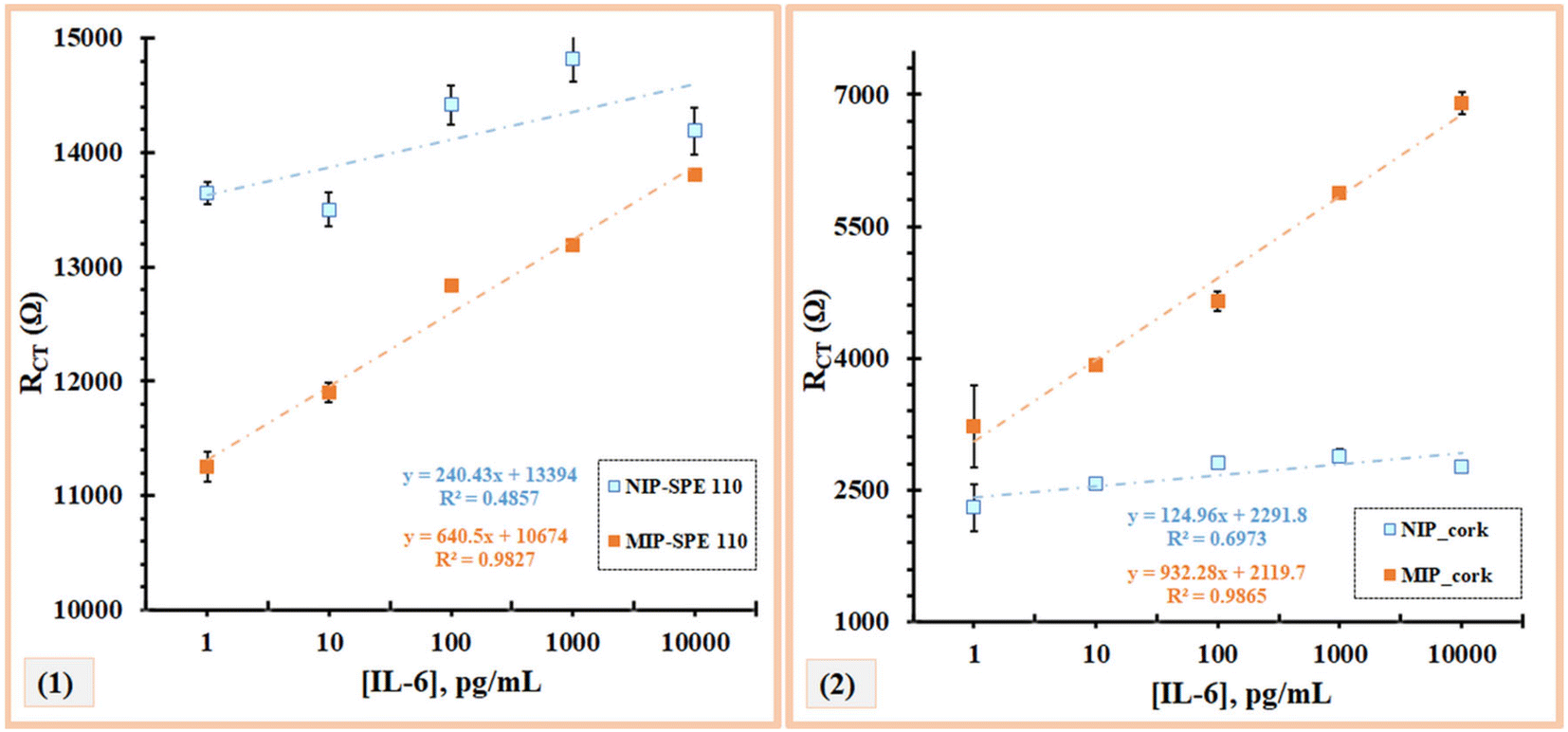 | ||
| Fig. 5 Calibration curves of the C-SPE electrodes (1) and homemade cork–SPE (2) with different concentrations of IL-6 in PBS (pH 5). The measurements were performed in 5 mM K3[Fe(CN)6] and K4[Fe(CN)6] prepared in 0.1 M KCl. | ||
On the other hand, in both NIPs, there was no linear response with the presence of increasing concentrations of IL-6. In the C-SPE, very short intervals between the different patterns were observed, with no response, while in cork–SPE, there was a random response, especially at the concentrations of 10 pg mL−1 and 1000 pg mL−1 (Fig. 5). These results agreed with what was expected, since the NIP does not present cavities in the polymer matrix for the detection of IL-6, thereby also confirming that there is little non-specific interaction between the polymer layer and IL-6.
Regarding the calibration of C-SPE and cork–SPE, it was found that only the protein-imprinted electrodes (MIP) showed a linear behaviour within 1 pg mL−1 to 10000 pg mL−1 (Fig. 5). The material NIP showed a random behaviour. For both electrodes (C-SPE and cork–SPE), it was found that both MIPs had better analytical performance, with correlation coefficients of 0.9812 and 0.9865, respectively, and both values were significantly higher than those of NIPs (no linear behaviour). Comparing the analytical performance of the C-SPE and cork–SPE MIPs, it can be observed that the sensors prepared on cork had a higher slope of 932 [Ω per decade concentration] compared to C-SPE, 704 [Ω per decade concentration] and a similar R2, suggesting that the cork substrate could improve the performance of the sensors (Fig. 5).
3.3 Application of biosensors for IL-6 detection in human serum
After calibrating the IL-6 biosensor in PBS, its performance was explored in a more realistic biofluid context. Thus, the same concentrations of standard solutions were prepared in Cormay serum (control material) diluted a thousand times in buffer solution at pH 5. Fig. S2 (ESI†) shows the EIS spectra of the calibration curves for the MIP and NIP-based sensors in C-SPEs (A1 and B1) and cork–SPE (A2 and B2).According to Fig. S3 (ESI†), a larger increase in the diameter of the Nyquist semicircle was observed for MIPs than for NIPs. An inversion of the slope of the calibration curves was observed for the C-SPEs. This could be attributed to possible interfering factors in the serum matrix that could interact with the ink and alter the net charge of the protein. In addition, the MIP and NIP sensors behaved oppositely in cork–SPE (A2), and the resistance to charge transfer increased with increasing protein concentration. This behaviour was similar to that observed during calibrations in serum samples (Fig. S4) (ESI†).
Empirically, both MIPs were found to have better analytical performance for both C-SPE and cork–SPE, with correlation coefficients of 0.9952 and 0.9704, respectively, and both slopes were higher than those of NIPs. Moreover, (2) shows that the slope of MIP was 760 [Ω (pg mL−1)−1], which was higher than that of NIP, which was 582 [Ω (pg mL−1)−1]. These results show that the cork electrodes give consistent results and that, as expected, the calibration curve in the spiked serum has the same profile as the calibration curve in buffer, suggesting that the serum does not have a strong influence on the MIP surface area.
3.4 Selectivity study
Selectivity tests were then performed to evaluate the ability of the sensor to distinguish IL-6 protein from other species present in biological fluids. In this way, fixed concentrations of IL-6 were incubated on the sensor surface along with various interfering species at concentrations corresponding to normal physiological conditions.This study was performed with IL-6 (100 pg mL−1), glucose (0.7 mg mL−1), urea (0.2 mg mL−1), and BSA diluted one thousand times in PBS buffer, pH 5 (1 mg mL−1) (Fig. 6). Incubation was performed for 20 minutes at room temperature and the respective interfering substances were prepared in buffer, pH 5. The lower the value of the percentage of interference, the lower the interference caused by the compound under study.
 | ||
| Fig. 6 Selectivity study by a mixed solution method for the following possible interfering species: urea, glucose and BSA. | ||
From the analysis in Fig. 6, it is evident that each interfering substance slightly affects the electrochemical signal. The mean deviation (%) of the electrical signal produced by each interfering substance compared with the control (IL-6) was 8% for glucose, 9% for urea, and 15% for BSA. Observing the low percentages, it can be concluded from this study that there was no significant deviation in the interfering signals, and therefore the sensor was found to be selective for the determination of IL-6 in synthetic human serum.
4. Conclusions
The development of selective electrochemical sensors is a recurrent approach and has recently evolved considerably. Their contribution in the medical field is the main objective of the research, where it has been highlighted by monitoring the clinical conditions of patients. In this work, an electrochemical sensor was developed by electrochemical polymerization with a 3-APBA monomer to detect IL-6 protein and support the screening of this biomarker for inflammatory responses. However, it is important to note that this biomarker is non-specific and helps to complement an assay with specific biomarkers to support the screening of the onset and progression of AD.After all major optimization, the analytical performance of both sensors was evaluated, and good analytical responses were obtained with calibration curves in both PBS and Cormay serum, with correlation coefficients above 0.97 for the MIPs and lower values for the NIPs. To complete this ideology, these two devices managed to obtain a linear response starting from 1 pg mL−1, i.e., they have a detection limit below the physiological value of IL-6 in humans.
To date, the use of natural products is widespread, and they are used in all industries. Through the development of this work, it was possible to prove this ideology and show that it is feasible to combine the field of sensors with sustainability. The cork-based POCT biosensor was able to achieve better results than the conventional ceramic-based SPEs; moreover, it offers a decisive advantage of low cost and biodegradability of the PoCT device.
Author contributions
BC and DO contributed equally to this manuscript towards investigation, methodology, validation and writing – original draft. GV and APT contributed in investigation (surface characterisation) and methodology. MGS, AJD and FTM contributed towards conceptualization, resources, and writing – review & editing. SS contributed towards methodology, investigation and writing – review & editing.Conflicts of interest
There are no conflicts to declare.Acknowledgements
The authors acknowledge funding through project 2IQBioneuro with the reference (0624_2IQBIONEURO_6_E), entitled, Promotion of an R&I network in biological chemistry for the diagnosis and treatment of neurological diseases, EP-INTERREG V Spain Portugal (POCTEP). Daniela O. acknowledges funding from the Fundação para a Ciência e Tecnologia, I. P., through the PhD grant reference SFRH/BD/137832/2018. This work was also supported by multi-year funding of the European Union (FEDER funds through Compete) and National Funds (FCT/MCTES) through Project UID/QUI/50006/2019 and UIDB/04730/2020.References
- J. D. Gallardo, G. L. Sullivan, M. Tokaryk, J. E. Russell, G. R. Davies, K. V. Johns, A. P. Hunter, T. M. Watson and S. Sarp, ACS ES&T Water, 2022, 2, 527–538 Search PubMed.
- C. Liu, D. Chu, K. K. Zadeh, J. George, H. A. Young and G. Liu, Adv. Sci., 2021, 8(15), 2004433, DOI:10.1002/advs.202004433.
- G. Liu, C. Jiang, X. Lin and Y. Yang, View, 2021, 2(4), 20210003, DOI:10.1002/VIW.20210003.
- M. G. Dobson, P. Galvin and D. E. Barton, Expert Rev. Mol. Diagn., 2007, 7, 359–370 CrossRef CAS PubMed.
- S. N. Topkaya, M. Azimzadeh and M. Ozsoz, Electroanalysis, 2016, 28, 1402–1419 CrossRef CAS.
- R. Malhotra, V. Patel, J. P. Vaque, J. S. Gutkind and J. F. Rusling, Anal. Chem., 2010, 82, 3118–3123 CrossRef CAS PubMed.
- Y. Lou, T. He, F. Jiang, J. J. Shi and J. J. Zhu, Talanta, 2014, 122, 135–139 CrossRef CAS PubMed.
- J. J. Shi, T. T. He, F. Jiang, E. S. Abdel-Halim and J. J. Zhu, Biosens. Bioelectron., 2014, 55, 51–56 CrossRef CAS PubMed.
- C. Russell, A. C. Ward, V. Vezza, P. Hoskisson, D. Alcorn, D. P. Steenson and D. K. Corrigan, Biosens. Bioelectron., 2019, 126, 806–814 CrossRef CAS PubMed.
- E. B. Aydin, Talanta, 2020, 215, 120909, DOI:10.1016/j.talanta.2020.120909.
- M. Tertis, B. Ciui, M. Suciu, R. Sandulescu and C. Cristea, Electrochim. Acta, 2017, 258, 1208–1218 CrossRef CAS.
- M. Tertis, P. I. Leva, D. Bogdan, M. Suciub, F. Graur and C. Cristea, Biosens. Bioelectron., 2019, 137, 123–132, DOI:10.1016/j.bios.2019.111410.
- N. Chen, H. Yang, Q. Li, L. J. Song, S. C. B. Gopinath and D. Wu, Biotechnol. Appl. Biochem., 2021, 68(6), 1479–1485, DOI:10.1002/bab.2068.
- K. Haupt, A. V. Linares, M. Bompart and T. S. B. Bernadette, Mol. Imprinting, 2012, 325, 1–28 CAS.
- N. Ozcan, C. Karaman, N. Atar, O. Karaman and M. L. Yola, ECS J. Solid State Sci. Technol., 2020, 9, 121010, DOI:10.1149/2162-8777/abd149.
- M. d. L. Gonçalves, L. A. N. Truta, M. G. F. Sales and F. T. C. Moreira, Anal. Lett., 2021, 1–13 Search PubMed.
- Y. T. Yaman, O. A. Vural, G. Bolat and S. Abaci, Bioelectrochemistry, 2022, 145, 108053, DOI:10.1016/j.bioelechem.2022.108053.
- J. C. Bloom, R. S. Fischer, A. Kim, C. Snell, G. M. Parkin, D. A. Granger, S. W. Granger and E. A. Thomas, Int. J. Mol. Sci., 2020, 21(17), 6363, DOI:10.3390/ijms21176363.
- X. Wang, M. R. Lennartz, D. J. Loegering and J. A. Stenken, Cytokine+, 2008, 43, 15–19 CrossRef CAS PubMed.
- B. P. Correa, D. Oliveira, S. Sharma and F. T. C. Moreira, ACS Omega, 2022, 7(43), 39039–39044, DOI:10.1021/acsomega.2c04789.
- A. P. M. Tavares, M. H. de Sa and M. G. F. Sales, J. Electroanal. Chem., 2021, 880, 114922, DOI:10.1016/j.jelechem.2020.114922.
- P. S. Sharma, A. P. Le, F. D. Souza and W. Kutner, Anal. Bioanal. Chem., 2012, 402, 3177–3204 CrossRef CAS PubMed.
- J. Zhang, X. T. Guo, J. P. Zhou, G. Z. Liu and S. Y. Zhang, Mater. Sci. Eng., C, 2018, 91, 696–704 CrossRef CAS PubMed.
- F. Frantzen, K. Grimsrud, D. E. Heggli and E. Sundrehagen, J. Chromatogr. B: Biomed. Sci. Appl., 1995, 670, 37–45 CrossRef CAS PubMed.
- J. Erdossy, E. Kassa, A. Farkas and V. Horvath, Anal. Methods, 2017, 9, 4496–4503 RSC.
Footnote |
| † Electronic supplementary information (ESI) available. See DOI: https://doi.org/10.1039/d3sd00022b |
| This journal is © The Royal Society of Chemistry 2023 |