
 Open Access Article
 This Open Access Article is licensed under a Creative Commons Attribution-Non Commercial 3.0 Unported Licence
Integration of capillaric strain sensors toward recognition of human movements†
Hudson
Gasvoda
 ab,
Nick
Cmager
a,
Rana
Altay
ab,
Ju Young
Lee
a and
I. Emre
Araci
*a
ab,
Nick
Cmager
a,
Rana
Altay
ab,
Ju Young
Lee
a and
I. Emre
Araci
*a
aDepartment of Bioengineering, Santa Clara University, Santa Clara, CA 95050, USA. E-mail: iaraci@scu.edu
bDepartment of Mechanical Engineering, Santa Clara University, Santa Clara, CA 95050, USA
First published on 6th December 2022
Abstract
Capillaric strain sensors (CSSs) operate based on the volume expansion of closed microfluidic networks in response to linear strain and have tunable directionality and sensitivity in a large range. The unique advantages of CSSs for integrated sensor development can simplify the human movement recognition by eliminating the need for intensive computational power and reliance on machine learning algorithms. We borrowed strategies from electrical digital circuits for the integration of CSSs in OR and AND configurations. We have fabricated devices according to these strategies. To validate their functionality, we first performed tests on a benchtop model. We have mapped the strain field on the sensors using digital image correlation and used it in combination with a mathematical procedure that we have developed to accurately predict the response of the integrated CSSs (iCSSs). Finally, we have skin mounted the iCSS patches (2 × 2 cm2) and conducted tests on a human subject. The results demonstrate that skin-strain-field mapping will be an enabling tool for iCSS design toward the recognition of human movements.
1. Introduction
Wearable devices for continuous tracking of human movements1–3 will lead to better management of physical rehabilitation regimens for patients suffering from musculoskeletal conditions4–7 and to more accurate data for sports analytics,8–10 hence the improvement of individual and team performance. Skin mountable strain sensors (SMSSs) have been reported for detecting joint and muscle activities.11–15 In recent years, there has been considerable interest in the development of SMSSs with higher sensitivity, larger dynamic range, higher directionality, and with additional modalities for digital recognition.16–19 Amongst these, nanoparticle-doped elastomers,20–22 hydrogels,23–25 capacitive sensors,26–29 and microfluidic strain sensors13,21,30–34 have gained attraction. The capillaric strain sensors (CSSs) developed in our group under the category of microfluidic strain sensors have tunable performance parameters, can reach an ultra-high gauge factor (GF) (>1000), and inherently apply a small mechanical load on the human skin as they do not require metallic or semiconductor materials for functionality.13The recognition of human movements typically requires intensive computational power for processing and analyzing the signal from multiple sensors.35–37 We propose a concept where an integrated sensor is designed based on a priori information of the skin-strain-field (SSF) correlated with a specific human movement. Instead of relying on machine learning algorithms, we propose that a single integrated sensor is used to generate a signal in response to a unique movement (or set of movements) for movement recognition. Our proposed concept is summarized in Fig. 1. This new concept is called digital recognition of human movements as the device only counts a single movement or a single type of movement. One challenge in the accurate recognition of human movements using SSF measurements is the complexity of human biomechanics and its relation to skin deformations. The SSF can be measured using digital image correlation (DIC), which is a well-known optical technique to analyze the deformation of materials.38,39 DIC relies on the imaging of a random pattern (i.e., speckle) painted on the sample and compares the deformed image to the un-deformed reference image. DIC has been used for various biomechanical applications.40–43 Obropta et al. used 3D DIC for detecting lines of no extension on the skin surface of a large upper body area during arm movements.44 Barrios-Muriel et al. have used the SSF to design wearables with better comfort.45 Chen et al. employed mirror-assisted multi-view DIC to measure strain maps on the human skin and deformation.46 Alternatively, 2D DIC is preferred for the analysis of planar samples due to its simplicity.47
 | ||
| Fig. 1 The schematic showing the concept of digital human movement recognition using an integrated capillaric sensor design based on a priori information of the SSF. | ||
The fusion of multiple sensors is typically utilized to recognize human movements.48–51 However, this is not desirable, because interfacing multiple sensors with the human body is practically challenging from the user's point of view especially for continuous daily use. To address this issue and avoid dependence on difficult-to-use glove-based systems with multiple sensors, Araromi et al. have developed an e-textile sleeve-based system that can recognize hand gestures from muscle contractions using a strain-mediated contact in anisotropically resistive structures (SCARS) technology.52 However, this technology still relies on optical motion tracking and machine learning algorithms for gesture classification.
Unlike the traditional geometric or piezoresistive strain sensors, the CSS relies on the dilatometry (i.e., volume expansion) of closed microfluidic networks (CMNs) under linear strain. The volumetric expansion of CMNs applies a negative pressure (i.e., vacuum) on a microfluidic probe channel. Cheng et al. have used this phenomenon to eliminate the breaks in the circuit during the stretching of a liquid metal antenna.53 In the CSS, the displacement of an ionic liquid is quantified electrically by utilizing the corner flow on a probe channel. This operation principle of the CSS technology presents an advantage as it allows the isolation of the mechanosensitive CMNs from the fluidic probe channel. Fig. 2 shows a comparison between the traditional strain sensor and CSS (top) and their integration methods (bottom). Here the performances of the CMN region and the electrical probe channel can be individually controlled for the CSS, whereas the mechanical and electrical properties of the standard strain sensor are coupled. It is also shown here that the fluidic displacement due to the volumetric strain of multiple CMNs is additive, which allows the measurement of the cumulative strain on different skin locations with a single device. This provides new ways to integrate multiple strain sensors, hence, potentially simplifying the human movement recognition using skin mountable strain sensors.
 | ||
| Fig. 2 The schematic showing the comparison between the CSS and standard strain sensor. The CSS allows design-based configurability of sensitivity (length × width), strain threshold (fluid channel length), and directionality (length/width). In the standard strain sensor, the mechanical and electrical properties are coupled. The CSS response is additive when integrated as shown (bottom). | ||
In this study, we have developed two strategies to integrate CSSs: i) multiple CMNs connected to a single microfluidic channel and ii) the electrical connection of multiple microfluidic sensing channels in parallel. The first integration system is called the “OR configuration” because theoretically positive volumetric strain in any one of the CMNs will create a positive signal. Here, the term positive signal is used for a sensor response above a certain response threshold. The second integration system is called the “AND configuration” because theoretically all of the CMNs must have positive volumetric strain to get a positive signal. We have used 2D DIC to validate the operation of both strategies on a benchtop model by generating a wide range of strain-field types. Then, we conducted human tests and mapped the strain field on two 5 × 5 cm2 areas on the inner and outer biceps of a single human subject using 2D DIC. We have used this map to determine the best integration strategy and integrated CSS patch (2 × 2 cm2) location to distinguish elbow flexion with muscle contraction from elbow flexion alone.
2. Device design and integration strategies
As we have reported previously,13 the CSS has two main components: a microfluidic probe (i.e., sensing) channel and a liquid reservoir (i.e., a CMN) for an ionic liquid (IL). While essentially utilizing the same principles, in this study, we have made two improvements over our previous CSS. Firstly, we have moved the electrode connections to the end of the sensing channels (as opposed to the end of the liquid reservoir) to reduce the initial resistance, and secondly, we have created serpentine/horseshoe-shaped sensing and interconnected channels to eliminate their directional dependence. Fig. 3a shows two CSSs with two different types of liquid reservoir orientations. The horizontally aligned liquid reservoirs (labeled H) are more sensitive to the strain along the Y-axis and the vertically aligned liquid reservoirs (labeled V) are more sensitive to the strain along the X-axis. These sensors are tested on a benchtop mechanical system with a schematic shown in Fig. 3b (see the Methods section and Fig. S3† for additional details regarding the design and operation of the benchtop testing system) under a stepwise increasing uniform uniaxial strain. A base from PDMS, shown in grey color, is first molded and the sensors are bonded on this PDMS base (see the Methods section for fabrication details). Two strain directions, one parallel to the reservoir orientation and the other orthogonal to the reservoir orientation along the X- and Y-axes, are applied to each sensor. The resistance of each of these sensors with respect to time during such a test is shown in Fig. 3c. Fig. 3d shows the relative resistance change, ΔR/R, with respect to the applied strain. The GF value (GF = ΔR/R/ε) for each of the strain directions for both of the sensors is given as the slope of the linear fit and shown next to each line. Both sensors have approximately three times more sensitivity in response to the strain direction orthogonal to the reservoir orientation in comparison to the parallel direction, which is defined as directionality (directionality = GF⊥/GF‖). To quantify the chip-to-chip variations in the GF and directionality, we tested four devices and averaged the GF of four chips that resulted in GF⊥ = 74 ± 27 and GF‖ = 26 ± 11. The average strain threshold, where the linear fit lines cut the X-axis, is estimated to be 0.02. The sensor's response to the applied strain starts after this threshold strain value due to its design (see ref. 13 for the details of strain threshold control). The average directionality from the fabricated chips is shown in Fig. 3e and compared to the directionality of a CSS that has a liquid reservoir with the pattern of a horseshoe (see the inset in Fig. 3e for the sensor with a horseshoe pattern). The horseshoe patterned liquid reservoir has a directionality of about one clearly showing that serpentine/horseshoe channels suppress the directional dependence due to the improved circular symmetry.54 To investigate the tunability of the directionality, we have conducted computer simulations using a COMSOL model and varied the channel length of the reservoir channels. This study demonstrated that the directionality could be tuned from two to eight when the reservoir channel length is varied from 1 mm to 10 mm (see Fig. S4† for details). The 3 mm channel length resulted in a directionality of 3.8 in comparison to the experimentally obtained value of 3.1. | ||
| Fig. 3 a) Microscopy image of a CSS with horizontal liquid reservoirs (Y-sensitive) on the left and with vertical liquid reservoirs (X-sensitive) on the right. b) The schematic of the mechanical test setup. The location of the sensor on the PDMS base during the test is indicated with a pink rectangle. The strain on four of the flaps was applied by linear actuators as described in the Methods section. A label indicating the number and actuation direction of each flap is shown. c) Experimental resistance response of two CSSs under uniform uniaxial strain in two different directions. d) Relative electrical resistance change, ΔR/R, as a function of strain. The best linear fit to the experimental data is shown as the lines (solid lines for the orthogonal strain direction and dashed lines for the parallel strain direction) and the slope of these lines is used as the gauge factor (GF = ΔR/R/ε). The standard deviation of three repetitions of the experiment is shown as the error bars. e) The bar graph showing the comparison of directionality for a straight channel liquid reservoir and a horseshoe channel liquid reservoir. The inset shows the microscopy image of a CSS with the horseshoe patterned liquid reservoir. | ||
We have then integrated these CSSs in AND and OR configurations as shown in Fig. 4a and b, respectively. Each of the liquid reservoirs is labeled A, B, C, and D. Fig. 4a and b show a design where the liquid reservoirs (A, B, C, D) are aligned in an HHVV format. Theoretically, having more liquid reservoirs and sensor designs with other liquid reservoir orientation combinations is possible. The AND configuration shown in Fig. 4a electrically connects the two sensing channels in parallel using silver wires. In the OR configuration, all four liquid reservoirs are connected to a single sensing channel. First, we have calculated the theoretical response of each of these configurations assuming a two-dimensional (2D) uniform strain profile (i.e., the strain on ABCD is identical) (see the Methods section for the details of the calculation). The GF⊥ of 74 and GF‖ of 26 that were found as average values for a unit CSS are used in the calculations. The theoretically calculated relative resistance change for a hypothetical 2D strain matrix acting identically on each liquid reservoir is shown in Fig. 4c and d for AND and OR configurations, respectively. These calculations show that in the AND configuration the uniaxial strain response at 0.06 strain is more than 10 times smaller than that at the same strain value applied biaxially. This ratio for the OR configuration is approximately four. This suggests that the AND configuration would be more selective in detecting biaxial strain in comparison to the OR configuration. In addition, when an arbitrary threshold value of 72% of the maximum is selected, the relative resistance change values that satisfy this condition (shaded with the red area) are spread more diagonally in the AND configuration compared to the OR configuration. The OR configuration on the other hand significantly increases the sensitivity to both uniaxial and biaxial strains.
 | ||
| Fig. 4 a) Microscopy image of the chip with two CSSs integrated with AND connection. There are two sensing channels connected in parallel using silver electrode wires. b) Microscopy image of the chip with two CSSs integrated with OR connection with a single sensing channel. Both chips have four liquid reservoirs labeled A, B, C, and D, which are oriented as HHVV. c) The relative resistance change for a 2D strain profile on the sensor with the AND configuration. d) The relative resistance change for a 2D strain on the sensor with the OR configuration. | ||
3. Experimental characterization of the integrated CSSs on the mechanical test module
As shown by Obropta et al., the strain profile on the human skin is not uniform.44 Therefore, the response of the integrated CSSs (iCSSs) shown in Fig. 4a and b has to be tested under non-uniform strain configurations. The mechanical test module (i.e., strain-field-generator (SFG)) that we have developed is capable of generating several unique strain profiles. We have created a COMSOL model of the SFG to validate its successful operation (see the Methods section for the details of the computer model). The simulation results showing the deformation of the PDMS base under two strain configurations (X2 (left) and X1Y1 (right)) are shown in Fig. 5a. To obtain the experimental strain profiles, we have applied a speckle pattern on the PDMS base as shown in Fig. 5b and the images of the speckle pattern taken using a camera from a 30 cm distance are used for DIC analysis using open-source software NCORR55 (see the Methods section for details). Fig. 5c shows the strain profiles in two directions, εXX and εYY, obtained from computer simulations (on the left) and through DIC analysis (on the right) for four different configurations. The strain in εXY is not included, as it does not cause volume change.56 Here, X1X2 shows a uniform strain configuration, X2 shows a non-uniform strain configuration, X1Y1 shows a non-uniform strain configuration with a biaxial component (on the lower left liquid reservoir labeled B), and XXYY shows a biaxial strain configuration. The agreement between the simulation and DIC results shows that the mechanical test module works as designed and is capable of creating various strain fields.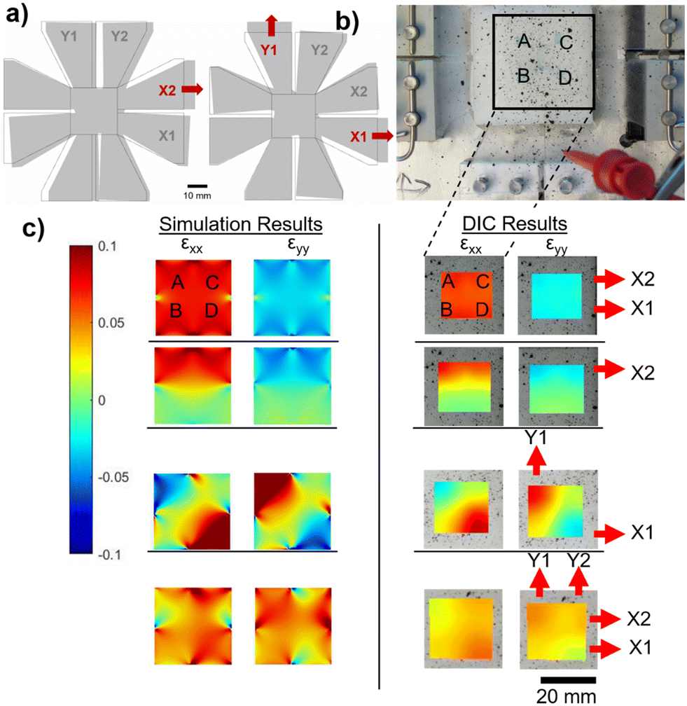 | ||
| Fig. 5 a) The simulation results showing the deformation of a PDMS base under two different strain configurations (left: X2, right: X1Y1; all displacements are 6 mm and only the clamps (not shown) on the opposite side of the activated flaps (indicated with red arrows) are fixed). b) The photograph of the PDMS microfluidic sensor (the liquid reservoir locations are labeled A, B, C, and D) bonded to a PDMS base that has a speckle pattern. The flaps of the base are connected to the clamps and to the linear actuators, or left free depending on the desired strain profile. c) Strain field heat maps for εXX and εYY, obtained using COMSOL simulations (left) and using DIC (right) for four configurations: XX (top), X2 (second row), X1Y1 (third row), and XXYY (bottom). | ||
As a next step, we have applied 10 unique strain configurations to the sensors bonded on the PDMS base with a speckle pattern. We have obtained both the images of the sample for DIC analysis and the sensor's electrical responses, simultaneously. The total sensor response, ΔR/R, is predicted more accurately using the experimental strain field values instead of assuming hypothetical strain values as in Fig. 4c and d (see the Methods section and ESI† Analysis for the prediction formulation). This time, however, the sensor response is divided by the maximum strain on the sensor to find the normalized sensor response, ΔR/R/εmax. The measured normalized sensor response is the electrical relative resistance change divided by the maximum strain on the sensor. The measured and calculated normalized strain responses are shown in Fig. 6. The biaxial configurations are shown in the grey shaded area. The agreement between the measured and calculated responses shows that our calculation method is suitable for designing an iCSS with a predicted response. It is immediately apparent that the AND configuration has a very small or no uniaxial response and the sensitivity of the OR is at least twice as large as the AND configuration. Both of these will lead to alternative design strategies depending on the goal of the application.
 | ||
| Fig. 6 The bar graphs for the normalized sensor response, ΔR/R/εmax, for 10 different strain configurations of the mechanical test module tested on the AND (top) and OR (bottom) integrated CSSs. The theoretically calculated (red) and measured (dark grey) strain responses are compared. The error bars on the measured OR response show the standard deviation in the response of three different chips and the error bars on the calculated values show the standard deviation in the DIC analysis from three tests. The grey-shaded areas show the biaxial configurations. The dashed lines show hypothetical threshold values for recognition of a strain-field configuration. | ||
Finally, to demonstrate the repeatability of the sensor we have tested an HHVV OR design on the SFG for more than 4 hours and 1000 cycles. In each cycle, strains in Y2 and YY configurations are applied to the sensor consecutively within 15 seconds. The sensor under this test can be seen in the ESI† Video. The response of the sensor during 1000 cycles is shown in Fig. 7. The Y2 levels are detected and shown with a red line. The insets show three zoomed-in regions of the signal around 0.7, 1, and 2.9 hours from left to right. The Y2 levels are seen in the insets clearly and connected with a red line for clarity. The reproducibility test signal has noise larger than that obtained in earlier tests conducted using a Mach 1, Biomomentum Inc.13 This is due to the large displacement error (15 ± 6%) and oscillation of the linear actuators (see the ESI† Video) in each cycle. Despite the high noise of the input signal, the Y2 levels are always significantly below the YY levels.
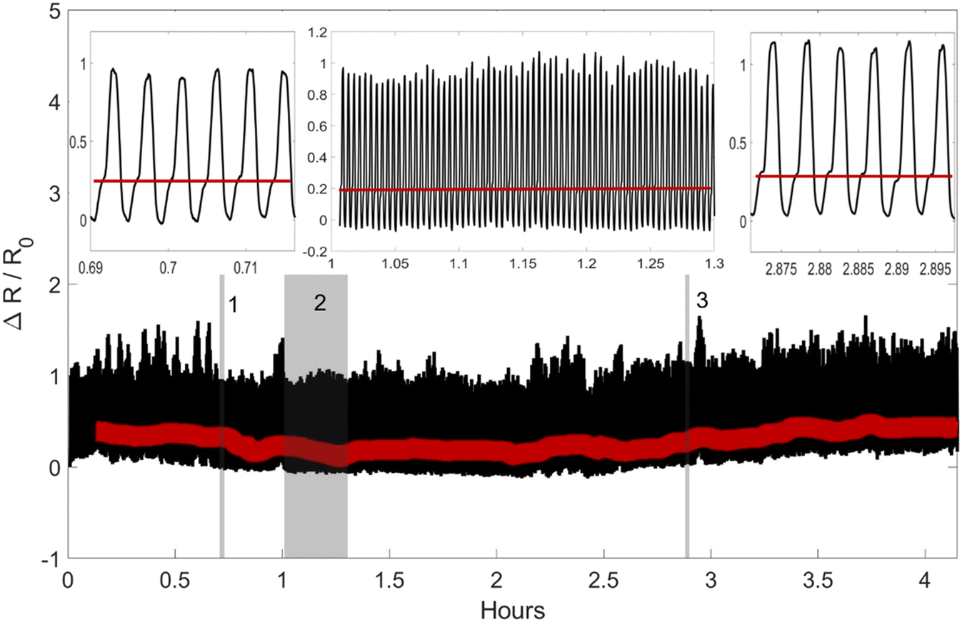 | ||
| Fig. 7 The reproducibility result of the HHVV OR sensor when the device is tested on the SFG for 4 hours and 15 minutes. In each cycle, the SFG completes the neutral state, Y2 state and YY state in 15 seconds. The insets are the zoomed in regions labeled 1, 2, and 3 (left to right). The red lines show approximately the location of the Y2 output. | ||
4. Human subject results
After the validation of our integration strategies on the benchtop tests, we have hypothesized that utilizing the biaxial specificity of the AND connection would constitute a suitable method for detecting a motion that involves contraction of large muscles such as the biceps, due to the exhibition of more biaxial strain on the skin during this type of motion.57 We have determined two locations for measuring the strain profile on the biceps: the inner biceps (shown in Fig. 8a and S2†) and the outer biceps on the opposite side (not shown here, see Fig. S3†). A temporary tattoo with a speckle pattern is applied on the volunteer's skin in these locations (see the Methods section for more details). These tattoos are imaged from a 100 cm distance for DIC analysis during distinct movements. This large working distance is selected to reduce the error from out-of-plane movements (e.g., for 1 cm out-of-plane movement 100 cm working distance will result in an error of 0.01 strain, which is 10 times smaller than the strain levels that we measure).58 The strain is characterized for straight-arm contraction (S-SC), straight-to-elbow flexion (S-F), and flexed arm contraction (F-FC). The strain fields (i.e., εXX, εYY) for these three movements are determined as shown in the heat maps provided in Fig. 8b–e. Various iCSSs are tested on different locations and orientations, which are overlaid on the strain heat maps as shown in Fig. 8b–e. The relative resistance change is measured and plotted during a test that included three repetitions of I) straight-arm contraction, II) straight-arm elbow flexion and III) straight-arm elbow flexion plus bicep contraction as a standard method, which is seen below the associated strain fields. Initially, we tested an HHHH OR sensor on the upper left (U-L) part of the tattoo (Fig. 8b). Notably, the response to motion III was significantly less than that to motion II because of the large negative strain of F-FC for εXX. Both motions II and III exhibit a small response in this test due to the small overall strain field. When an HHVV OR sensor is tested on the middle of the tattoo, we have obtained a response from motion III nearly twice as large as that from motion II (Fig. 8c). This is due to the positive εYY and nearly zero εXX for F-FC in this location. Although in agreement with the DIC results, it is interesting to note that neither of the locations shown in Fig. 8b and c produced any response for motion I. We have determined the right side of the tattoo to be more suitable for AND sensors, as we get more positive εXX for F-FC on the right side. Therefore, we have tested two HHVV AND sensors on the upper right (U-R) and lower right (L-R) as shown in Fig. 8d and e, respectively. Motion II resulted in a four to five times smaller signal compared to motion III, further improving the distinction between flexion and flexion plus contraction. The signal for L-R is three times larger compared to U-R due to the larger strain values for εYY on the lower side. In addition, the upper right corner is the only location that produced a signal for motion I, in agreement with the DIC results as the upper right has a positive value for both εXX and εYY for motion I. These results suggest that with the appropriate selection of a threshold value, an iCSS can be designed and placed to only count the motion of interest, hence providing a digital behavior.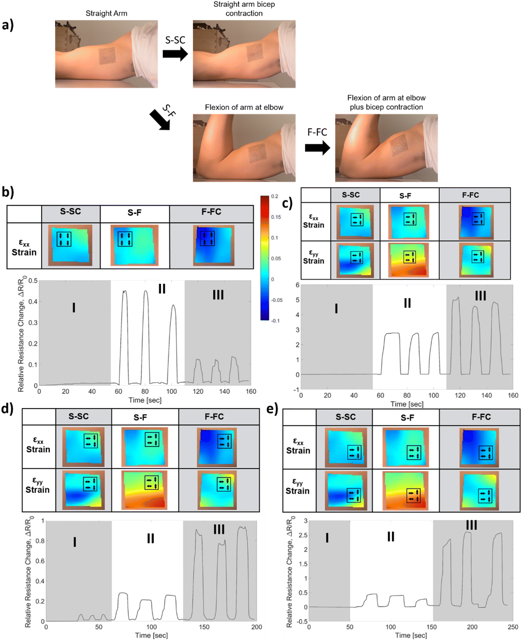 | ||
| Fig. 8 a) Photographs of the inner biceps with a 5 × 5 cm2 temporary tattoo during human arm motions in a standard test conducted to record the strain-field via DIC. S-SC: contraction of the bicep muscle while keeping the arm straight. S-F: flexion of the arm at slightly larger than 90°. F-FC: contraction of the biceps during flexion. b–e) The strain-field of the 5 × 5 cm2 tattoo overlaid with the sensor schematics, where the arrows show the orientation of the CMN (top) in comparison with the relative resistance change with respect to time for the three moves that are repeated three times (bottom). b) The HHHH OR on the upper left (εYY not shown, as HHHH is only sensitive to the x-direction). c) The HHVV OR on the middle. d) The HHVV AND on the upper right. e) The HHVV AND on the lower right. The S-FC strain-field can be calculated by adding S-F and F-FC together. | ||
After observing this qualitative agreement between the strain field results and the sensor response, we have made a quantitative comparison. The strain values from the human tests were used to calculate the expected relative resistance change during each motion for each sensor, in a similar manner described for Fig. 6. The calculated values are shown in comparison to the experimental values as a bar graph in Fig. 9. Overall, we have observed that the measured sensor response is at least four times smaller than the calculated values. This can be attributed to the alteration of the skin strain field due to the mechanical load of a 100 μm thick PDMS sensor with 1 MPa Young's modulus. Despite this difference, the measured sensor responses are consistent with the trends of calculated responses.
 | ||
| Fig. 9 The bar graph of the sensor response, ΔR/R, for five sensors tested in the inner biceps and two sensors tested in the outer biceps during three motions (types I II III labeled for each sensor test). The theoretically calculated (black, left axis) and measured (red, right axis) strain responses are compared. The grey shaded areas show the outer bicep results. | ||
5. Discussion
The simultaneous recording of DIC data during the iCSS operation allowed us to measure the strain-field affecting the individual liquid reservoirs under test. Based on this information, we have developed a theoretical procedure (see the Methods section and the ESI† Analysis) to calculate the expected iCSS response and showed the agreement between theoretical calculation and the measured response on the mechanical test module, SFG. To observe the importance of this approach in predicting the sensor response, we can compare the HHVV OR sensor's hypothetical and experimental biaxial responses. In Fig. 4d, the values on the diagonal line (i.e., εXX = εYY ≠ 0) provide ΔR/R for perfectly uniform biaxial strain and result in a theoretical sensitivity of ΔR/R/ε = 384. Our experimental biaxial response is shown by the XXYY in Fig. 6 (bottom bar graph) and provides ΔR/R/εmax = 210. It is seen that the experimentally observed response is nearly half of the calculated value in response to a hypothetical biaxial strain. This is due to the non-uniform strain field in the XXYY configuration as shown in Fig. 5c. Even though we have attempted to apply a uniform biaxial strain field, due to the actuator error and the design of our SFG, we have obtained an imperfect biaxial strain distribution. As a result, some liquid reservoirs experienced smaller strain values in comparison to others, hence reducing the total response of the sensor. The effect of this non-uniformity is predicted with our procedure and the DIC-based calculation agrees well with the experimental response as seen in Fig. 6. Although numerical simulations can analyze the strain-field on a simple planar mechanical model like the SFG, this will not be a straightforward task for systems that are more complex such as the human musculoskeletal system. DIC-based analysis provides strain-field information on the human skin during complex activities, hence eliminating the reliance on challenging computer simulations.When the OR and AND configuration results are compared in Fig. 6, we observe that the iCSS connected in the OR configuration results in a high sensor response to almost every uniaxial input that is orthogonal to one of the liquid reservoirs, as expected. Notably, the Y2 configuration for OR has the lowest response because Y2 strain affects two liquid reservoirs but both in the parallel direction, resulting in a low response as designed. In this case, a response threshold of around 25 (see the dashed line in Fig. 6) will be sufficient to distinguish other configurations from Y2, providing a mechanical OR logic operation. On the other hand, when we look at the AND response, we observe that none of the uniaxial strain configurations provide a high signal as expected. The high signals are only obtained from X1Y1 and XXYY, which cause orthogonal strain to two liquid reservoirs and biaxial strain to one liquid reservoir, and biaxial strain to all liquid reservoirs, respectively. Even though X1Y2 and X2Y2 have a biaxial strain on a single liquid reservoir, there is only one more liquid reservoir with an orthogonal strain, hence resulting in a low sensor response. Here, we can conclude that the iCSS with the AND configuration requires activation of at least three liquid reservoirs by either orthogonal or biaxial strain on them to exceed a response threshold value at 25 (see the dashed line in Fig. 6), thus working as an AND logic.
The main discrepancy between the predicted and measured sensor response in the human subject results is due to the mechanical load of the sensor on the skin reducing the overall strain on the liquid reservoirs. For a healthy skin with high elasticity, the in vivo Young's modulus (E) is in the range of 0.05–0.1 MPa (ref. 59 and 60) and the skin thickness on the biceps is around 1 mm.61 The sensor with E = 1 MPa and 0.1 mm thickness will increase the effective Young's modulus to two to three times its initial value. This increase in tensile stiffness is sufficient to explain the reduction in the sensor response when it is considered that the application of load on the skin during natural joint angle change and muscle contraction does not satisfy the no-slip condition. However, even when a linear correction factor is included in the predictions, for some chip locations and motion types, the agreement with the measured response is low. This indicates that 1) the skin strain field is affected by the sensor mechanical load differently for different motion types, and/or 2) the small alignment errors of the sensor are causing considerable prediction errors. As a remedy to these problems, in a future study, the strain field on the skin will be measured after the sensor is mounted on the skin and more precise alignment strategies will be developed. Another explanation for the discrepancies in Fig. 9 is the errors in 2D DIC. The 2D DIC is selected for its simplicity in hardware and data analysis for the measurement of small surface areas, which are assumed as planar. Although the benchtop strain-field results are in quantitative agreement with the simulations, the out-of-plane movements and tilting of the arm during the human tests could be causing errors that make the quantitative analysis difficult on the human skin. The agreement between the 2D DIC and 3D DIC for small surface areas has to be further investigated for more precise iCSS design and skin mounting guidance.
6. Conclusion
Capillaric strain sensors (CSSs) have tunable directionality and sensitivity depending on the channel architecture of the liquid reservoirs. Two strategies that are borrowed from electrical digital circuits (i.e., AND, OR) are presented here for integrated CSS design with the goal of digital recognition of human movements. The required strain field information was obtained using 2D DIC on a benchtop mechanical model and on a human subject test. The simultaneous detection of the strain field and sensor response in the mechanical model resulted in an accurate prediction of the expected sensor responses. This demonstrates that the theoretical and experimental procedures reported here can guide the integrated CSS design. On the human subject tests, the independent measurements of the sensor response and the skin strain field showed qualitative agreement between the predicted and measured sensor responses. Even though there were some discrepancies in the human subject test predictions, the AND connection that was placed and oriented according to the guidance of the strain field results was successful in suppressing the elbow flexion motion response that does not include any muscle contraction, while maintaining a large response to flexion plus bicep contraction. The mechano-fluidic logic circuit design realized with the integration of the CSSs is a promising paradigm for the digital recognition of human movements.7. Methods
7.1. Device fabrication
To make the polydimethylsiloxane (PDMS) microfluidic sensors, a silicon wafer mold was fabricated using negative photoresist SU-82050 following the manufacturer's protocols for 50 μm height features. These master molds were used to create PDMS sensors through replica molding. Momentive RTV 615 (RS. Hughes) was mixed in a 10![[thin space (1/6-em)]](https://www.rsc.org/images/entities/char_2009.gif) :1 ratio (A:B) and spun on the mold at 500 rpm to reach a thickness of 140 μm. The PDMS was then peeled from the wafer and the electrode connection and the inlet/outlets were punched using a 0.5 mm handheld puncher. For sensor characterization testing, a base was created as a bottom layer using a 3D-PLA printed mold. A 10:1 mixture of PDMS was poured into this mold, which formed a base with a thickness of 1 mm after curing at 40 °C for five hours. The first 140 μm patterned layer was bonded to the center of the base using air plasma from Harrick Plasma PDC-001. The sensor was then filled with 1-butyl-3-methylimidazolium dicyanamide ([BMIM][N(CN)2]) mixed with a blue food dye for visibility. Then 50 μm diameter silver wires (SurePure Chemetals, 99.99% purity) were inserted. To seal the sensor, the surface was exposed to plasma using an Electrotechnic Products plasma wand, and all of the inlet/outlets except for the air reservoir outlet were filled with NOA 65 and UV cured for sealing. Then Loctite Epoxy with a 30 min cure time was used on top of the NOA to strengthen the sealing. The overall dimensions of the sensor were 20 mm by 20 mm with channel dimensions of 100 μm width × 50 μm height.
:1 ratio (A:B) and spun on the mold at 500 rpm to reach a thickness of 140 μm. The PDMS was then peeled from the wafer and the electrode connection and the inlet/outlets were punched using a 0.5 mm handheld puncher. For sensor characterization testing, a base was created as a bottom layer using a 3D-PLA printed mold. A 10:1 mixture of PDMS was poured into this mold, which formed a base with a thickness of 1 mm after curing at 40 °C for five hours. The first 140 μm patterned layer was bonded to the center of the base using air plasma from Harrick Plasma PDC-001. The sensor was then filled with 1-butyl-3-methylimidazolium dicyanamide ([BMIM][N(CN)2]) mixed with a blue food dye for visibility. Then 50 μm diameter silver wires (SurePure Chemetals, 99.99% purity) were inserted. To seal the sensor, the surface was exposed to plasma using an Electrotechnic Products plasma wand, and all of the inlet/outlets except for the air reservoir outlet were filled with NOA 65 and UV cured for sealing. Then Loctite Epoxy with a 30 min cure time was used on top of the NOA to strengthen the sealing. The overall dimensions of the sensor were 20 mm by 20 mm with channel dimensions of 100 μm width × 50 μm height.
For human testing, the sensors were fabricated similarly. One difference was the thickness of the thin PDMS film, which was 75 μm and achieved by spinning PDMS at 900 rpm on the mold. A second difference was for the bottom layer, which was created on a blank wafer by spinning PDMS at 3200 rpm to create a film with a 25 μm thickness. The remainder of the process is identical, and some other details can be found in ref. 13.
7.2. Device testing
To collect the sensor response a Keysight 34461A benchtop digital multimeter (DMM) was utilized to collect the resistance of the sensing channel while under strain from the SFG. The DMM was connected to the chip via microwire connectors as positive and negative leads. The DMM was used as an ohmmeter with a collection interval of 0.4 s.7.3. Benchtop mechanical test module
To characterize the sensor response on the benchtop, a mechanical test module that is capable of generating a wide range of strain fields was built (see Fig. S1† for the schematics). The module includes an aluminum plate with 4 linear Actuonix L12-50-50-6-P actuators connected to linear tracks and 4 fixed connection points that interface with the flaps on the base of the chip. The actuators have a max stroke length of 50 mm and we used a maximum of 6 mm stroke. A 40 mm × 40 mm white block of PTFE was placed in the middle of the connectors to provide support to the PDMS base and provide a white background for contrast for imaging acquisition. Castor oil was used as a lubricant to reduce friction between the PDMS and the PTFE. An in-house LabView code was created to control the actuators in the desired sequence.7.4. Image acquisition and DIC analysis
A Raspberry Pi Zero with a Raspberry Pi Camera attachment and a telephoto lens was used to capture images of the speckle pattern on the sensor. The camera lens was positioned 33 cm above the PTFE block. A Python script was used to record images with no displacement applied and with 6 mm displacement applied through the actuators. The sensor and base were speckled using a toothbrush with black Crayola water-based paint to create a speckle pattern for the DIC to track to calculate the strain. 2D-DIC plotted the strain fields, εXX and εYY, of the sensor to further characterize the sensor.2D-DIC images were taken on both the inner and outer upper arm to determine where to place different sensors. The reference and strained tattoo images were obtained using an iPhone 12 Pro Max showing the zero position of the arm and the final position of 1 of the 3 distinct movements that occurred. The camera was positioned 100 cm away to reduce artificial strain due to the muscle bulging. To align the camera plane in parallel to the test region, a laser was attached to the phone and was aligned parallel to the camera direction. The laser was then reflected off an 18 × 18 mm coverslip that was placed on the upper arm by a biocompatible skin adhesive. When the reflected beam hits directly back on the laser, the camera was then accepted to be in proper alignment with the pattern. The cover slip was then removed from the speckle pattern and the images were recorded.
The speckle pattern for the arm was computer generated. Using an HP inkjet printer, the design was printed on part A of the temporary tattoo kit from Heat Press Nation and later covered by part B of the same kit. A detailed description of the process can be found in ref. 62. By the same method, a 5.7 × 5.7 cm2 square border was printed and placed around the speckle-patterned area to ensure repeatable iCSS placement on the arm.
NCORR, an open-source 2D digital image correlation module in MATLAB software, was used to analyze the images taken to determine the strain applied to the liquid reservoirs. After the DIC parameters were set according to the NCORR manual, DIC analysis was performed by correlating the specified subset from the reference to the deformed sample image. It was important to keep the correlation factor as low as possible and to keep the number of Gauss iterations under 50 to obtain satisfactory results. The displacement plots (u and v), as well as εXX, εXY, and εYY strain plots, were obtained.
7.5. Mathematical formulation for the sensor response prediction
The strain values (i.e., εXX, εYY) on each of the liquid reservoirs (ABCD) were determined either hypothetically (for Fig. 4c and d) or experimentally by averaging the strain values under each reservoir from the SSF maps (for Fig. 6 and 9). Each one of the four εXX and four εYY values was categorized as either orthogonal or parallel with respect to their associated liquid reservoir orientations. The orthogonal and parallel group values were added together (∑ε⊥, ∑ε‖) within themselves. The strain threshold value (i.e., the strain required to induce corner flow in the probe channel) was subtracted from the orthogonal group as it is the dominant strain direction. Then, the total strain in each group was multiplied with the single liquid reservoir's theoretical GF contributions from the orthogonal ( ) and parallel strain components (
 ) (see ESI† Analysis for the definition and calculation of
  ). These two values were added together to find the theoretical sensor response, ΔR/R =
  (∑ε⊥ − εth) +
  .
.
7.6. Numerical modeling of PDMS base deformation
We used COMSOL Multiphysics software to generate a 3D model of the elastomeric PDMS base. The structural mechanics module was implemented in these simulations. A Young's modulus of 0.75 MPa and a Poisson's ratio of 0.49 were chosen for the elastomer. We used the physics-controlled automatic meshing function to discretize the system with a fine mesh. The dimensions of the base match the experimental base used. To simulate the strain, a prescribed displacement function of 6 mm was applied at the side surface of each flap simulating the function of the actuators. A fixed constraint was applied on the opposite flaps, simulating the function of the fixed clamps. The strain tensor components were visualized in x- and y- directions to compare to the DIC results.Data availability
The data that support the findings of this study are available from the corresponding author upon reasonable request.Ethics statement
All experiments were performed in accordance with the institutional guidelines and approved by the Institutional Review Board at Santa Clara University with the protocol number 21-06-1630. Informed consent was obtained from the human participant.Author contributions
I. E. A. and H. G. designed the research and developed the mathematical formulation; H. G. performed the iCSS experiments; H. G. and N. C. performed the DIC experiments; J. Y. L. drew the designs in AutoCAD and fabricated the horseshoe liquid reservoir sensors and tested them; R. A. conducted the directionality simulations; I. E. A. guided the whole research; I. E. A., H. G., and N. C. analyzed the data and wrote the paper.Conflicts of interest
The authors declare no competing financial or non-financial interests.Acknowledgements
This project was supported by the NSF program 19-582, grant 2045087. The device were fabricated in the Center for Nanostructures at Santa Clara University.References
- Kenry, J. C. Yeo and C. T. Lim, Emerging flexible and wearable physical sensing platforms for healthcare and biomedical applications, Microsyst. Nanoeng., 2016, 2, 16043, DOI:10.1038/micronano.2016.43.
- E. Rovini, C. Maremmani and F. Cavallo, How Wearable Sensors Can Support Parkinson's Disease Diagnosis and Treatment: A Systematic Review, Front. Neurosci., 2017, 11, 555, DOI:10.3389/fnins.2017.00555.
- C. Wong, Z. Q. Zhang, B. Lo and G. Z. Yang, Wearable Sensing for Solid Biomechanics: A Review, IEEE Sens. J., 2015, 15(5), 2747–2760, DOI:10.1109/jsen.2015.2393883.
- C. Vallati, A. Virdis, M. Gesi, N. Carbonaro and A. Tognetti, ePhysio: A Wearables-Enabled Platform for the Remote Management of Musculoskeletal Diseases, Sensors, 2019, 19(1), 2, DOI:10.3390/s19010002.
- Q. Wang, P. Markopoulos, B. Yu, W. Chen and A. Timmermans, Interactive wearable systems for upper body rehabilitation: a systematic review, J. Neuroeng. Rehabil., 2017, 14, 20, DOI:10.1186/s12984-017-0229-y.
- L. Simpson, M. M. Maharaj and R. J. Mobbs, The role of wearables in spinal posture analysis: a systematic review, BMC Musculoskeletal Disord., 2019, 20, 55, DOI:10.1186/s12891-019-2430-6.
- F. Porciuncula, et al., Wearable Movement Sensors for Rehabilitation: A Focused Review of Technological and Clinical Advances, PM&R, 2018, 10(9), S220–S232, DOI:10.1016/j.pmrj.2018.06.013.
- E. Preatoni, et al., The Use of Wearable Sensors for Preventing, Assessing, and Informing Recovery from Sport-Related Musculoskeletal Injuries: A Systematic Scoping Review, Sensors, 2022, 22(9), 3225, DOI:10.3390/s22093225.
- A. Zadeh, D. Taylor, M. Bertsos, T. Tillman, N. Nosoudi and S. Bruce, Predicting Sports Injuries with Wearable Technology and Data Analysis, Inf. Syst. Front., 2021, 23(4), 1023–1037, DOI:10.1007/s10796-020-10018-3.
- D. R. Seshadri, et al., Wearable sensors for monitoring the internal and external workload of the athlete, NPJ Digit. Med., 2019, 2, 71, DOI:10.1038/s41746-019-0149-2.
- Z. Q. Song, et al., Breathable and Skin-Mountable Strain Sensor with Tunable Stretchability, Sensitivity, and Linearity via Surface Strain Delocalization for Versatile Skin Activities' Recognition, ACS Appl. Mater. Interfaces, 2018, 10(49), 42826–42836, DOI:10.1021/acsami.8b14365.
- N. S. Lu, C. Lu, S. X. Yang and J. Rogers, Highly Sensitive Skin-Mountable Strain Gauges Based Entirely on Elastomers, Adv. Funct. Mater., 2012, 22(19), 4044–4050, DOI:10.1002/adfm.201200498.
- L. R. Yepes, E. Demir, J. Y. Lee, R. P. Sun, M. Smuck and I. E. Araci, Skin Mountable Capillaric Strain Sensor with Ultrahigh Sensitivity and Direction Specificity, Adv. Mater. Technol., 2020, 5(12), 2000631, DOI:10.1002/admt.202000631.
- J. D. Pegan, et al., Skin-mountable stretch sensor for wearable health monitoring, Nanoscale, 2016, 8(39), 17295–17303, 10.1039/c6nr04467k.
- J. Guo, et al., Wearable and Skin-Mountable Fiber-Optic Strain Sensors Interrogated by a Free-Running, Dual-Comb Fiber Laser, Adv. Opt. Mater., 2019, 7(12), 1900086, DOI:10.1002/adom.201900086.
- J. Kim, Y. Lee, M. Kang, L. Hu, S. Zhao and J. H. Ahn, 2D Materials for Skin-Mountable Electronic Devices, Adv. Mater., 2021, 33(47), 2005858, DOI:10.1002/adma.202005858.
- G. Ge, W. Huang, J. J. Shao and X. C. Dong, Recent progress of flexible and wearable strain sensors for human-motion monitoring, J. Semicond., 2018, 39(1), 011012, DOI:10.1088/1674-4926/39/1/011012 , (in English).
- E. K. Lee, M. K. Kim and C. H. Lee, Skin-Mountable Biosensors and Therapeutics: A Review, in Annual Review of Biomedical Engineering, ed. M. L. Yamush, 2019, vol. 21, pp. 299–323 Search PubMed.
- M. Amjadi, K. U. Kyung, I. Park and M. Sitti, Stretchable, Skin-Mountable, and Wearable Strain Sensors and Their Potential Applications: A Review, Adv. Funct. Mater., 2016, 26(11), 1678–1698, DOI:10.1002/adfm.201504755.
- K. K. Kim, et al., Highly Sensitive and Stretchable Multidimensional Strain Sensor with Prestrained Anisotropic Metal Nanowire Percolation Networks, Nano Lett., 2015, 15(8), 5240–5247, DOI:10.1021/acs.nanolett.5b01505.
- H. Songjia, et al., Multiscale nanowire-microfluidic hybrid strain sensors with high sensitivity and stretchability, npj Flexible Electron., 2018, 2(16) DOI:10.1038/s41528-018-0029-x.
- B. Taherkhani, M. M. Chegini and P. Rahmani, Highly sensitive, piezoresistive, silicon/graphite powder-based, auxetic sensor with linear sensing performance, Sens. Actuators, A, 2022, 345, 113776, DOI:10.1016/j.sna.2022.113776.
- F. Hao, L. Y. Wang, B. L. Chen, L. Qiu, J. Nie and G. P. Ma, Bifunctional Smart Hydrogel Dressing with Strain Sensitivity and NIR-Responsive Performance, ACS Appl. Mater. Interfaces, 2021, 13(39), 46938–46950, DOI:10.1021/acsami.1c15312.
- Y. G. Yan, et al., A Dual-Responsive, Freezing-Tolerant Hydrogel Sensor and Related Thermal- and Strain-Sensitive Mechanisms, ACS Appl. Polym. Mater., 2021, 3(3), 1479–1487, DOI:10.1021/acsapm.0c01346.
- M. J. Zhao, et al., A Packaged and Reusable Hydrogel Strain Sensor with Conformal Adhesion to Skin for Human Motions Monitoring, Adv. Mater. Interfaces, 2022, 9(6), 2101786, DOI:10.1002/admi.202101786.
- A. Frutiger, et al., Capacitive Soft Strain Sensors via Multicore-Shell Fiber Printing, Adv. Mater., 2015, 27(15), 2440–2446, DOI:10.1002/adma.201500072.
- O. Glauser, D. Panozzo, O. Hilliges and O. Sorkine-Hornung, Deformation Capture via Soft and Stretchable Sensor Arrays, ACM Trans. Graphics, 2019, 38(2), 16, DOI:10.1145/3311972 , (in English).
- Z. J. Zhu, R. Y. Li and T. R. Pan, Imperceptible Epidermal-Iontronic Interface for Wearable Sensing, Adv. Mater., 2018, 30(6), 9, DOI:10.1002/adma.201705122 , (in English).
- L. Cai, et al., Super-stretchable, Transparent Carbon Nanotube-Based Capacitive Strain Sensors for Human Motion Detection, Sci. Rep., 2013, 3, 3048, DOI:10.1038/srep03048.
- B. Q. Nie, R. Y. Li, J. D. Brandt and T. R. Pan, Microfluidic tactile sensors for three-dimensional contact force measurements, Lab Chip, 2014, 14(22), 4344–4353, 10.1039/c4lc00746h.
- J. C. Yeo, Kenry and C. T. Lim, Emergence of microfluidic wearable technologies, Lab Chip, 2016, 16(21), 4082–4090, 10.1039/c6lc00926c , (in English).
- S. G. Yoon, H. J. Koo and S. T. Chang, Highly Stretchable and Transparent Microfluidic Strain Sensors for Monitoring Human Body Motions, ACS Appl. Mater. Interfaces, 2015, 7(49), 27562–27570, DOI:10.1021/acsami.5b08404.
- S. Agaoglu, P. Diep, M. Martini, K. T. Samudhyatha, M. Baday and I. E. Araci, Ultra-sensitive microfluidic wearable strain sensor for intraocular pressure monitoring, Lab Chip, 2018, 18(22), 3471–3483, 10.1039/c8lc00758f.
- L. N. Mao, et al., Configurable direction sensitivity of skin-mounted microfluidic strain sensor with auxetic metamaterial, Lab Chip, 2022, 22(8), 1630–1639, 10.1039/d2lc00141a.
- M. Guo and Z. L. Wang, Segmentation and recognition of human motion sequences using wearable inertial sensors, Multimed. Tools Appl., 2018, 77(16), 21201–21220, DOI:10.1007/s11042-017-5573-1.
- Y. F. Chen and C. Shen, Performance Analysis of Smartphone-Sensor Behavior for Human Activity Recognition, IEEE Access, 2017, 5, 3095–3110, DOI:10.1109/access.2017.2676168.
- I. H. Lopez-Nava and A. Munoz-Melendez, Wearable Inertial Sensors for Human Motion Analysis: A Review, IEEE Sens. J., 2016, 16(22), 7821–7834, DOI:10.1109/jsen.2016.2609392.
- B. Pan, K. M. Qian, H. M. Xie and A. Asundi, Two-dimensional digital image correlation for in-plane displacement and strain measurement: a review, Meas. Sci. Technol., 2009, 20(6), 062001, DOI:10.1088/0957-0233/20/6/062001.
- M. Palanca, G. Tozzi and L. Cristofolini, The use of digital image correlation in the biomechanical area: a review, Int. Biomech., 2016, 3(1), 1–21 CrossRef.
- D. S. Zhang and D. D. Arola, Applications of digital image correlation to biological tissues, J. Biomed. Opt., 2004, 9(4), 691–699, DOI:10.1117/1.1753270.
- A. N. Annaidh, K. Bruyere, M. Destrade, M. D. Gilchrist and M. Ottenio, Characterization of the anisotropic mechanical properties of excised human skin, J. Mech. Behav. Biomed. Mater., 2012, 5(1), 139–148, DOI:10.1016/j.jmbbm.2011.08.016.
- N. Miura, T. Sakamoto, Y. Aoyagi and S. Yoneyama, Visualizing surface strain distribution of facial skin using stereovision, Theor. Appl. Mech. Lett., 2016, 6(4), 167–170, DOI:10.1016/j.taml.2016.05.005.
- H. G. Shin, S. Timilsina, K. S. Sohn and J. S. Kim, Digital Image Correlation Compatible Mechanoluminescent Skin for Structural Health Monitoring, Adv. Sci., 2022, 9(11), 2105889, DOI:10.1002/advs.202105889.
- E. W. Obropta and D. J. Newman, Skin strain fields at the shoulder joint for mechanical counter pressure space suit development, in IEEE Aerospace Conference, 2016 Search PubMed.
- J. Barrios-Muriel, F. R. Sanchez, F. J. Alonso and D. R. Salgado, Design of Semirigid Wearable Devices Based on Skin Strain Analysis, J. Biomech. Eng., 2019, 141(2), 021008, DOI:10.1115/1.4040250.
- B. Chen, K. Genovese and B. Pan, In vivo panoramic human skin shape and deformation measurement using mirror-assisted multi-view digital image correlation, J. Mech. Behav. Biomed. Mater., 2020, 110, 103936, DOI:10.1016/j.jmbbm.2020.103936.
- N. A. Hoult, W. A. Take, C. Lee and M. Dutton, Experimental accuracy of two dimensional strain measurements using Digital Image Correlation, Eng. Struct., 2013, 46, 718–726, DOI:10.1016/j.engstruct.2012.08.018.
- K. Lu, L. Y. Yang, F. Seoane, F. Abtahi, M. Forsman and K. Lindecrantz, Fusion of Heart Rate, Respiration and Motion Measurements from a Wearable Sensor System to Enhance Energy Expenditure Estimation, Sensors, 2018, 18(9), 3092, DOI:10.3390/s18093092.
- I. Herrera-Luna, E. J. Rechy-Ramirez, H. V. Rios-Figueroa and A. Marin-Hernandez, Sensor Fusion Used in Applications for Hand Rehabilitation: A Systematic Review, IEEE Sens. J., 2019, 19(10), 3581–3592, DOI:10.1109/jsen.2019.2897083.
- C. Vu and J. Kim, Human Motion Recognition Using E-textile Sensor and Adaptive Neuro-Fuzzy Inference System, Fibers Polym., 2018, 19(12), 2657–2666, DOI:10.1007/s12221-018-8019-0.
- W. Maetzler, J. Domingos, K. Srulijes, J. J. Ferreira and B. R. Bloem, Quantitative Wearable Sensors for Objective Assessment of Parkinson's Disease, Mov. Disord., 2013, 28(12), 1628–1637, DOI:10.1002/mds.25628.
- O. A. Araromi, et al., Ultra-sensitive and resilient compliant strain gauges for soft machines, Nature, 2020, 587(7833), 219–224, DOI:10.1038/s41586-020-2892-6.
- S. Cheng, A. Rydberg, K. Hjort and Z. G. Wu, Liquid metal stretchable unbalanced loop antenna, Appl. Phys. Lett., 2009, 94(14), 144103, DOI:10.1063/1.3114381.
- J. A. Rogers, T. Someya and Y. Huang, Materials and Mechanics for Stretchable Electronics, Science, 2010, 327(5973), 1603–1607, DOI:10.1126/science.1182383.
- J. Blaber, B. Adair and A. Antoniou, Ncorr: Open-Source 2D Digital Image Correlation Matlab Software, Exp. Mech., 2015, 55(6), 1105–1122, DOI:10.1007/s11340-015-0009-1.
- A. Bertram and R. Glüge, Solid Mechanics, Springer Cham, Switzerland, 1st edn, 2015, p. 318 Search PubMed.
- A. Murai, Q. Hong, K. Yamane and J. Hodgins, Dynamic skin deformation simulation using musculoskeletal model and soft tissue dynamics, Comput. Vis. Media, 2017, 3(1), 49–60, DOI:10.1007/s41095-016-0065-1.
- M. A. Sutton, J. H. Yan, V. Tiwari, H. W. Schreier and J. J. Orteu, The effect of out-of-plane motion on 2D and 3D digital image correlation measurements, Opt. Lasers Eng., 2008, 46(10), 746–757, DOI:10.1016/j.optlaseng.2008.05.005 , (in English).
- C. Pailler-Mattei, S. Bec and H. Zahouani, In vivo measurements of the elastic mechanical properties of human skin by indentation tests, Med. Eng. Phys., 2008, 30(5), 599–606, DOI:10.1016/j.medengphy.2007.06.011.
- J. H. Yuan, et al., Computational models for the determination of depth-dependent mechanical properties of skin with a soft, flexible measurement device, Proc. R. Soc. A, 2016, 472(2194), 20160225, DOI:10.1098/rspa.2016.0225.
- K. H. Sim, M. S. Hwang, S. Y. Kim, H. M. Lee, J. Y. Chang and M. K. Lee, The appropriateness of the length of insulin needles based on determination of skin and subcutaneous fat thickness in the abdomen and upper arm in patients with type 2 diabetes, Diabetes Metab. J., 2014, 38(2), 120–133, DOI:10.4093/dmj.2014.38.2.120 , (in eng).
- G. Quino, et al., Speckle patterns for DIC in challenging scenarios: rapid application and impact endurance, Meas. Sci. Technol., 2021, 32(1), 015203, DOI:10.1088/1361-6501/abaae8.
Footnote |
| † Electronic supplementary information (ESI) available. See DOI: https://doi.org/10.1039/d2sd00201a |
| This journal is © The Royal Society of Chemistry 2023 |