
 Open Access Article
 This Open Access Article is licensed under a Creative Commons Attribution-Non Commercial 3.0 Unported Licence
Bidirectional manipulation of iodine redox kinetics in aqueous Fe–I2 electrochemistry†
Weiwei
Zhang‡
 ab,
Mingli
Wang‡
ac,
Hong
Zhang
*d,
Lin
Fu
e,
Wenli
Zhang
f,
Yupeng
Yuan
*a and
Ke
Lu
*ac
ab,
Mingli
Wang‡
ac,
Hong
Zhang
*d,
Lin
Fu
e,
Wenli
Zhang
f,
Yupeng
Yuan
*a and
Ke
Lu
*ac
aInstitutes of Physical Science and Information Technology, School of Materials Science and Engineering, Key Laboratory of Structure and Functional Regulation of Hybrid Materials of Ministry of Education, Anhui University, Hefei, Anhui 230601, China. E-mail: yupengyuan@ahu.edu.cn; luke@ahu.edu.cn
bSchool of Chemistry and Chemical Engineering, Qufu Normal University, Qufu, Shandong 273165, China
cHefei National Laboratory for Physical Sciences at the Microscale, Hefei, Anhui 230026, China
dSchool of Chemistry and Chemical Engineering, Harbin Institute of Technology, Harbin, Heilongjiang 150001, China. E-mail: zhanghonghit@hit.edu.cn
eSchool of Chemistry and Chemical Engineering, Guizhou University, Guiyang, Guizhou 550025, China
fSchool of Chemical Engineering and Light Industry, Guangdong University of Technology, Guangzhou, Guangdong 510006, China
First published on 20th October 2023
Abstract
Catalyzing conversion is a promising approach to unlock the theoretical potentials of the I2/I− redox couple in aqueous Fe–I2 electrochemistry. However, most reported results only obtain one-directional efficient iodine conversion and cannot realize a balance of full reduction and reoxidation, thereby resulting in rapid capacity decay and/or low coulombic efficiency. Herein, the concept of bidirectional catalysis based on a core–shell structured composite cathode design, which accelerates the formation and the decomposition of FeI2 simultaneously during battery dynamic cycling, is proposed to regulate the Fe–I2 electrochemical reactions. Notably, the functional matrix integrates N, P co-doping and FeP nanocrystals into a carbon shell to achieve bidirectional catalysis. More specifically, the carbon shell acts as a physical barrier to effectively capture active species within its confined environment, N, P heteroatoms function better in directing the iodine reduction and FeP facilitates the decomposition of FeI2. As confirmed with in situ and ex situ analysis, the Fe–I2 cell operates a one-step but reversible I2/FeI2 pair with enhanced kinetics. Consequently, the composite cathode exhibits a reversible Fe2+ storage capability of 202 mA h g−1 with a capacity fading rate of 0.016% per cycle over 500 cycles. Further, a stable pouch cell was fabricated and yielded an energy density of 146 W h kgiodine−1. Moreover, postmortem analysis reveals that the capacity decay of the Fe–I2 cell originates from anodic degradation rather than the accumulation of inactive iodine. This study represents a promising direction to manipulate iodine redox in rechargeable metal–iodine batteries.
Introduction
Aqueous secondary batteries that possess an intrinsic nature of high safety and environmental friendliness are promising for large-scale energy storage technology.1–4 Iron (Fe) metal batteries that use Fe2+ as charge carriers have aroused scientists' interest owing to the high capacity of Fe (960 mA h g−1 or 7557 mA h cm−3), its abundance as a raw material (63![[thin space (1/6-em)]](https://www.rsc.org/images/entities/char_2009.gif) 000 ppm in the Earth's crust vs. 79 ppm for Zn), low redox potential (∼0.44 V vs. SHE, standard hydrogen electrode), and exceedingly low price ($458 per ton in contrast to $3059 for Zn).5–7 However, the strong electrostatic interactions between iron ions and the lattice of insertion-type cathodes (e.g., Prussian blue analogs, PBA) render unsatisfactory capacity and poor cycling stability.6,8–10 Thus, coupling cathodes based on conversion chemistries with Fe metal anodes offers a promising option for realizing advanced aqueous iron batteries. Among the conversion cathode candidates, the iodine (I2) cathode is attractive because of its high redox potential (∼0.54 V vs. SHE) and high abundance in nature (55 μgiodine Locean−1).11–14 The former feature endows the aqueous Fe–I2 battery with high working potential of 0.975 V (Fig. 1a); the latter character takes advantage of cost-effectiveness (Fig. 1b).
000 ppm in the Earth's crust vs. 79 ppm for Zn), low redox potential (∼0.44 V vs. SHE, standard hydrogen electrode), and exceedingly low price ($458 per ton in contrast to $3059 for Zn).5–7 However, the strong electrostatic interactions between iron ions and the lattice of insertion-type cathodes (e.g., Prussian blue analogs, PBA) render unsatisfactory capacity and poor cycling stability.6,8–10 Thus, coupling cathodes based on conversion chemistries with Fe metal anodes offers a promising option for realizing advanced aqueous iron batteries. Among the conversion cathode candidates, the iodine (I2) cathode is attractive because of its high redox potential (∼0.54 V vs. SHE) and high abundance in nature (55 μgiodine Locean−1).11–14 The former feature endows the aqueous Fe–I2 battery with high working potential of 0.975 V (Fig. 1a); the latter character takes advantage of cost-effectiveness (Fig. 1b).
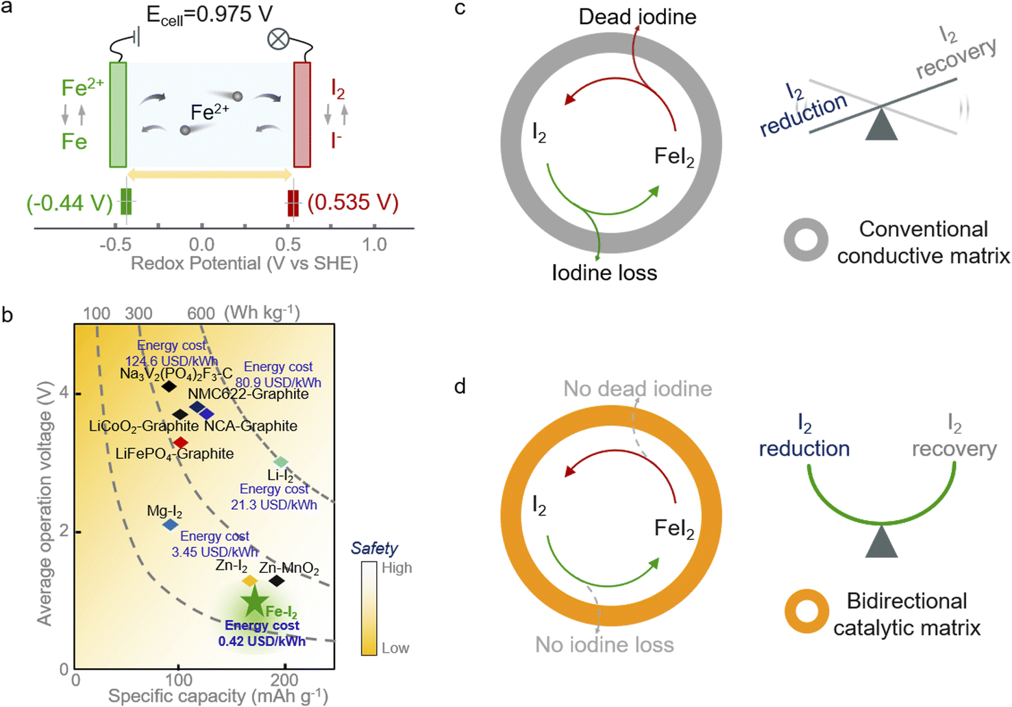 | ||
| Fig. 1 Electrochemical performance and schematic illustration of the Fe–I2 redox electrochemistry. (a) Reactions in Fe–I2 batteries and redox potentials of Fe2+/Fe and I2/I−. The charge/discharge process is enabled by the reversible conversions between I2 and Fe. (b) Comparison of different batteries in terms of energy density, operation voltage, specific capacity, cost, and safety. The reported data are calculated based on the mass of active materials. (c and d) Schematic diagram of the electrochemical redox processes of iodine species loaded in different matrices, highlighting the manipulability of iodine redox based on the bidirectional catalytic matrix. | ||
Albeit with appealing promise, the notorious shuttling of active iodine, the sluggish redox kinetics, and the high activation barrier of discharge products compromise the further development of Fe–I2 electrochemistry.15–17 Efforts have been devoted to addressing the issues initiated by iodine cathodes. One can utilize a porous carbon matrix for hosting active iodine and then physically suppress the dissolution of iodine species.18–20 Considering the insufficient interactions between nonpolar carbon and iodine species, the physical confinement cannot effectively handle the shuttle effect and fails in accelerating the intrinsically sluggish redox kinetics. These factors lead to the continuous loss of active species and limited discharge product reutilization efficiency during battery dynamic cycling (Fig. 1c).21,22 Therefore, the introduction of active hotspots and/or polar substrates, such as heteroatom-doped carbon, PBA, and MXene, to boost the iodine redox conversion could fundamentally solve the shuttle and facilitate the sluggish kinetics instead of roughly blocking the migration of iodine species into the electrolyte.23–25 In addition, metal–iodine batteries based on advanced multi-electron transfer modes and strategies to address the safety concerns associated with metallic anodes also have been proposed in the pursuit of high energy density.26–28 Nevertheless, most of the reported catalysts normally work in one direction (reduction or oxidation), leading to the enrichment of unconverted iodine species and then decreasing the overall electrochemical response. Hence, the development of a functional cathodic host with bidirectional catalytic activity that simultaneously accelerates the reduction and oxidation processes of iodine is urgently required.
In this study, we propose a core–shell structured iodine cathode with bidirectional catalytic activity to facilitate both reduction of iodine and oxidation of FeI2 discharge products during battery dynamic cycling (Fig. 1d). Elemental iodine was encapsulated in a porous carbon fiber behaving as the core, and the functional carbon shell decorated with FeP nanocrystals and co-doped with nitrogen and phosphorus (I2/FeP-NPC-CC) provided a confined environment for iodine redox. Moreover, the heteroatom moieties and FeP hotspots function better in accelerating the iodine reduction and decreasing the FeI2 reactivation energy barrier, respectively, which overall directed the reversible one-step iodine conversion with enhanced redox kinetics. Accordingly, the assembled Fe–I2 cell delivers a high Fe2+ ion storage capability of 202 mA h g−1 and exhibits an excellent lifespan of over 500 cycles with 92% capacity retention. Simultaneously, an Fe–I2 pouch cell was also prepared and delivered an energy density of 146 W h kgcathode−1. Operando and postmortem spectroscopic analyses reveal the working and degradation mechanism of the as-prepared Fe–I2 cells. Our results offer a new insight into tunable iodine redox for high-performance metal–iodine batteries.
Results and discussion
Structural characterization of bifunctional carbon-based catalytic matrix
The core–shell structured catalytic matrix that supported the iodine cathode for the aqueous Fe–I2 battery was prepared by a two-step approach, as shown in Fig. 2a. Initially, Fe3+ ions were employed as initiators for triggering the in situ chemical oxidative polymerization of aniline monomers in the presence of phytic acid (PA) to produce the cross-linked polyaniline (PANi)-Fen+-PA hydrogel that interfacially wrapped on the surface of wiper cloth fibers.29,30 During this process, Fe3+ ions could be reduced to Fe2+ ions and entrapped by the heteroatoms within the interconnected polymer networks. PA served as the crosslinker and was grafted between PANi chains via spontaneous free-radical polymerization. Subsequently, the PANi-coated wiper cloth was directly annealed at 900 °C for 1 h under N2 flow in the presence of NaH2PO2 powder as the phosphorus source, resulting in a core–shell structured carbon cloth (FeP-NPC-CC), in which the carbon shell was doped with iron phosphide and dual nitrogen, phosphorus atoms.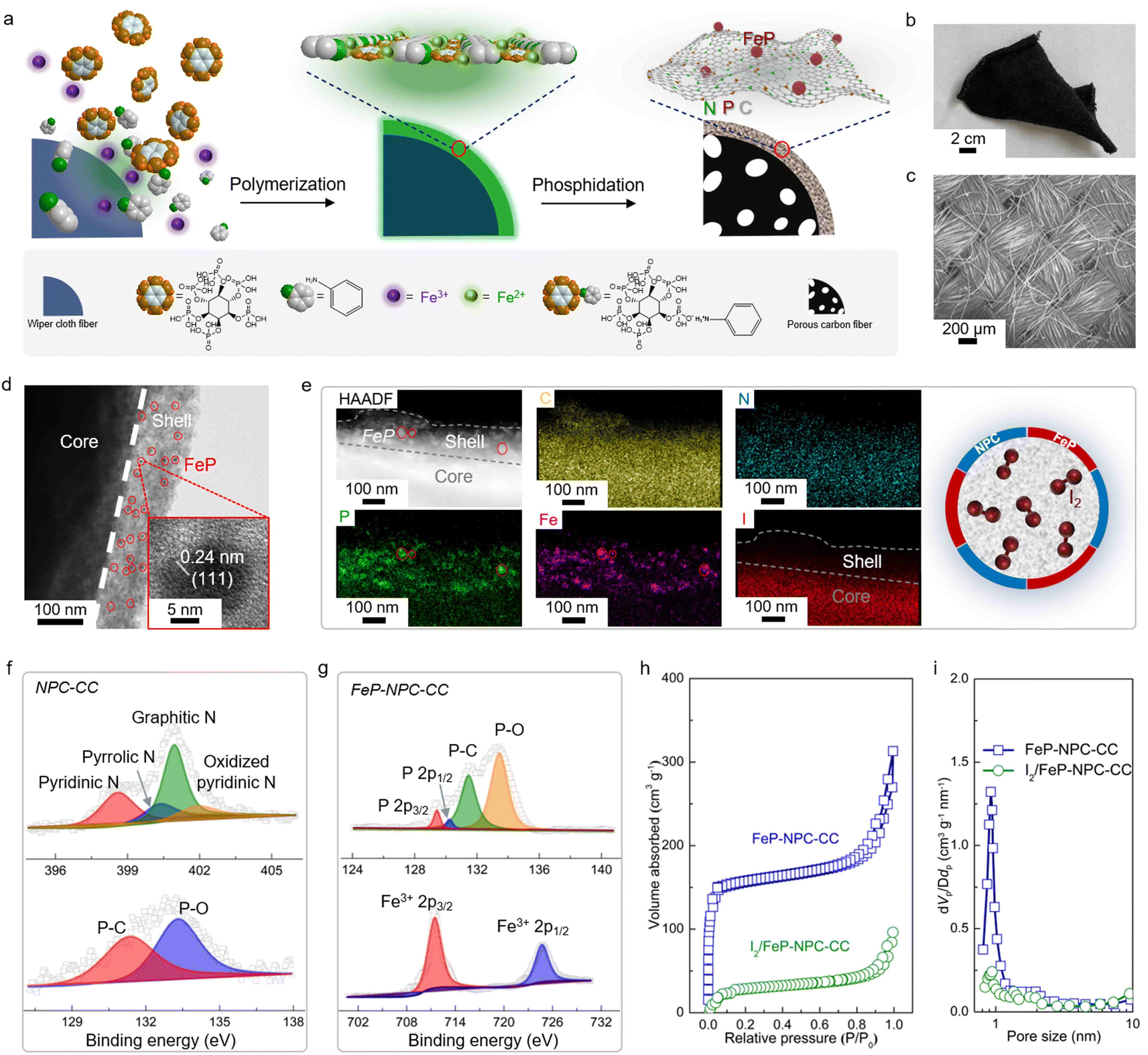 | ||
| Fig. 2 Schematic illustration and structural characterization of bifunctional FeP-NPC-CC matrix. (a) Schematic of fabrication process and structure of FeP-NPC-CC composite. (b) Digital photograph, (c) SEM image, and (d) TEM image of FeP-NPC-CC. (e) HAADF-STEM image, and the corresponding elemental mapping and schematic of the iodine-loaded I2/FeP-NPC-CC. (f) High-resolution N 1s and P 2p XPS spectra of NPC-CC. (g) P 2p and Fe 2p XPS spectra of FeP-NPC-CC. (h and i) Nitrogen adsorption–desorption isotherms and the corresponding pore size distributions of FeP-NPC-CC and I2/FeP-NPC-CC. | ||
Scanning electron microscopy (SEM) and optical images confirm the free-standing and highly flexible nature of the FeP-NPC-CC carbon scaffold, demonstrating the feasibility for practical manufacture (Fig. 2b and c). Transmission electron microscopy (TEM) observations confirm the successful formation of the FeP-NPC-CC core–shell structure and the thickness of the carbon sheath of about 100 nm (Fig. 2d). Moreover, highly distributed FeP nanoparticles are embedded in the carbon sheath framework (red circles). The high-resolution TEM image (Fig. 2d, inset) also shows the lattice fringes of 0.24 nm, corresponding to the (111) facet of FeP.31 Then, elemental iodine was impregnated into the porous carbon framework by surface adsorption from an iodine-saturated aqueous solution.32 The high-angle annular dark-field scanning TEM (HAADF-STEM) image and corresponding elemental mappings (Fig. 2e) indicate the uniform distribution of Fe, N, P, and I elements. Notably, the element iodine is well confined within the confinement environment as offered by the catalytic carbon shell, which could facilitate the full conversion of active iodine during battery cycling (schematic of Fig. 2e). The phase information of the as-prepared samples is further determined by X-ray diffraction (XRD) patterns. As shown in Fig. S1,† the formation of FeP was further confirmed, agreeing well with the above TEM analysis. Of note, no obvious diffraction peak of iodine can be observed, suggesting the highly dispersed amorphous nature of impregnated iodine.33
Typical X-ray photoelectron spectroscopy (XPS) results for NPC-CC and FeP-NPC-CC are provided in Fig. 2f and g. As expected, the XPS spectra of NPC-CC show peaks of C and N, as well as a P peak arising mainly from the PA precursor. Specifically, the fitted XPS peaks of P 2p and N 1s XPS spectra of NPC-CC centered at 131.3 eV and ∼401.2 eV correspond P–C bond and graphitic nitrogen, respectively, indicating the successful doping of P and N heteroatoms into the carbon network via the pyrolysis procedure.34 Moreover, the Fe 2p spectrum of FeP-NPC-CC exhibits two peaks ascribed to FeP at binding energies of 711.3 eV and 724.5 eV, which are also reflected in the P 2p XPS spectra that shows two peaks at 129.3 and 130.1 eV, further confirming the formation of FeP.35 Brunauer–Emmett–Teller (BET) analysis and corresponding pore-size distribution were conducted to investigate the porous structure of the FeP-NPC-CC matrix before and after iodine loading (Fig. 2h and i). FeP-NPC-CC shows a high BET surface area of 469 m2 g−1 and type IV isotherm curves, indicating abundant micropores. This favorable surface configuration is beneficial for the adsorption and transformation of iodine species. After iodine loading, the specific surface area sharply decreased to 98 m2 g−1, along with diminished pore size, indicating the successful encapsulation of iodine within the pores of FeP-NPC-CC.
Interactions between iodine species and catalytic matrix and the manipulatable iodine conversion
It has been reported that the strong interaction between iodine species and matrix plays a key role in highly efficient iodine redox.36 In this regard, thermogravimetric analysis (TGA) was employed to evaluate the interaction between functional host and iodine and determine the content of active materials. In accordance, FeP-NPC-CC exhibits the highest onset evaporation temperature at around 185 °C compared with control samples of I2/CC and pure iodine (Fig. 3a). The significantly enhanced thermal stability for the iodine loaded within the functional matrix could be ascribed to its strong interaction with iodine, which would lead to better cycling stability for batteries.37,38 Moreover, the FeP-NPC-CC framework with a porous structure could realize a high iodine content of ∼52%. To further demonstrate the absorption ability of matrixes towards iodine species, each composite iodine cathode was immersed in FeSO4 (1 M) electrolyte and kept for over 10 h. Obviously, the color of the FeSO4 solution mixed with the I2/FeP-NPC-CC cathode has no measurable change, indicating that FeP-NPC-CC shows the strongest absorption ability compared with the counterparts (inset, Fig. 3b). Ultraviolet-visible (UV-vis) results further support the above speculation and the color change arising from iodine or polyiodide dissolution rather than from dissolved iron ions (Fig.s S2 and S3†). As shown, the absorbance at ∼220 nm sharply decreased with the presence of the NPC component compared with I2/CC, and I2/FeP-NPC-CC displays a negligible absorption peak. This suggests that NPC and FeP could work synergistically to enable the nearly full iodine confinement.39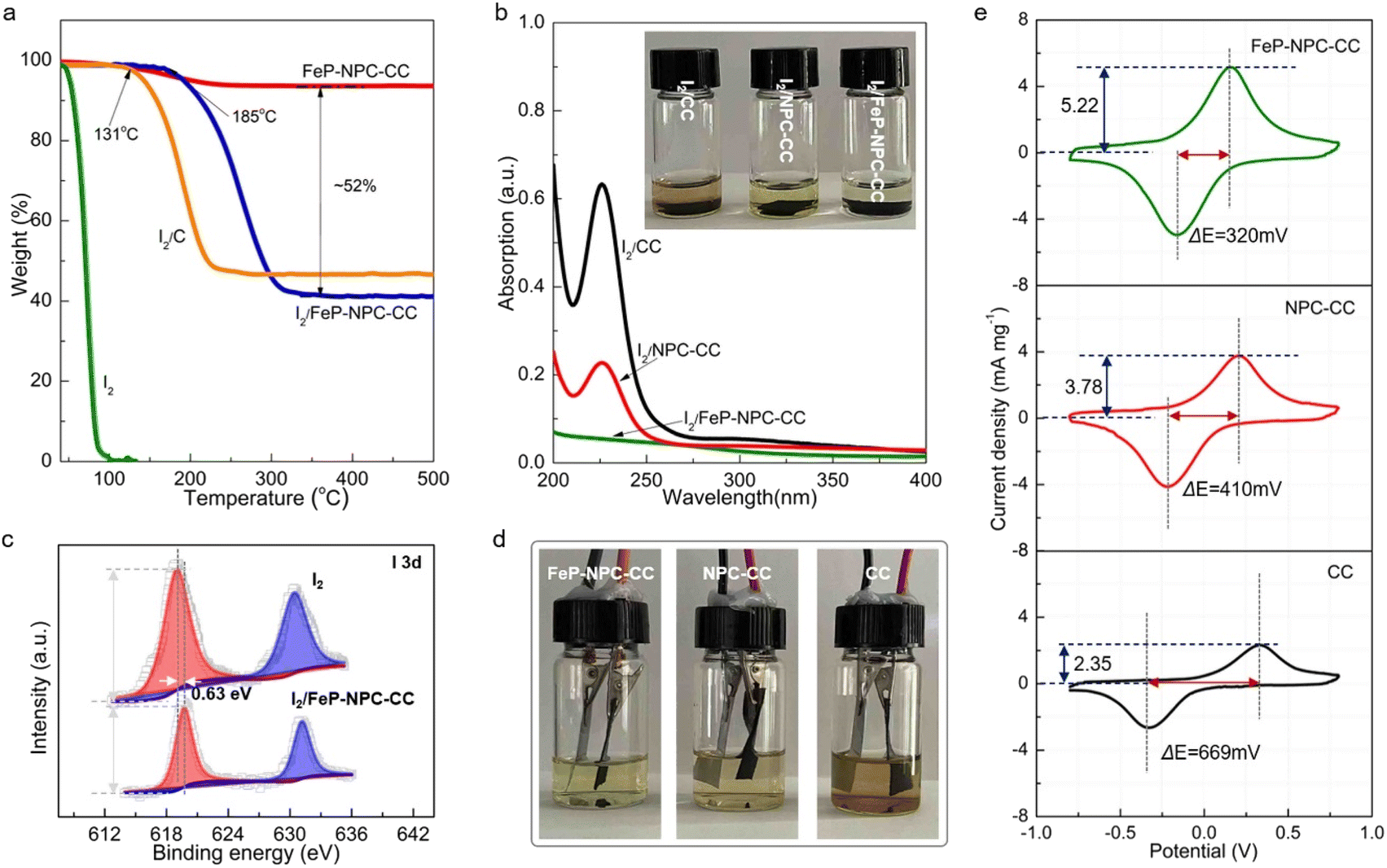 | ||
| Fig. 3 Interactions between matrix and iodine and matrix-dependent catalytic effects on iodine conversion. (a) TGA curves of different materials. (b) UV-visible absorption spectra of I2 solution after soaking with different materials (inset: photographs for different I2 solutions). (c) I 3d XPS spectra of I2 and I2/FeP-NPC-CC. (d) Photographs of Fe–I2 batteries with I2/FeP-NPC-CC, I2/NPC-CC, and I2/CC cathodes after the cycling stability test. (e) CV curves of symmetric cells with FeP-NPC-CC, NPC-CC, and CC electrodes. | ||
XPS analysis reveals the underlying mechanism of the enhanced interaction between iodine and the catalytic matrix. As shown in Fig. 3c, the two peaks of I 3d shift about 0.63 eV to the positions with higher binding energy compared to pure iodine with a slight decrease of peak intensity, indicating the chemical interaction between iodine and matrix.40 And the binding energy shift also suggests the formation of chemical bonds between substrate and iodine. This phenomenon suggests an electron transfer from iodine to functional host, and this charge redistribution and strong binding affinity could stabilize the iodine species, thereby enhancing the cycling stability of the Fe–I2 cell. Therefore, a multi-porous structure and the incorporation of heteroatoms and FeP nanocrystals are crucial for the high loading of active components, which provide an efficient method to tune the cycling stability of iodine. Then, optically transparent Fe–I2 beaker cells were assembled to validate the superior absorption ability of the functional host during the battery dynamic cycling process, exploiting the color change of the electrolyte. Fig. 3d shows that the electrolyte of the I2/FeP-NPC-CC//Fe cell is lighter in color than that of I2/NPC-CC and I2/CC. This result offers visual evidence of very low iodine species content in the electrolyte and demonstrates effective trapping by the synergistic effect of FeP and NPC under practical conditions. Apart from the initial absorption process, the redox kinetics of iodine species on hosts were further probed using symmetric cells and corresponding cyclic voltammetry (CV) curves.41 The large current and small voltage differences demonstrate the positive effect of catalytic activity in the kinetic conversion of iodine species (Fig. 3e). In comparison with NPC-CC (3.78 mA mg−1, 410 mV) and CC (2.35 mA mg−1, 669 mV), the highest response current (5.22 mA mg−1) and smallest peak separation (320 mV) are afforded by FeP-NPC-CC. This manifests that FeP-NPC-CC significantly enhances the kinetics of the reversible electrochemical reactions of the I−/I3− redox couple.
Mechanistic investigation of reversible iodine conversion and electrochemical performance of Fe–I2 cell
To evaluate the benefit of the catalytic matrix for the electrochemical performance of Fe–I2 cells, coin cells were assembled with different cathodes, and galvanostatic charge–discharge tests were conducted. As can be seen in Fig. 4a, the I2/FeP-NPC-CC cathode exhibits a high specific capacity of 202 mA h g−1 at 200 mA g−1, suggesting a high iodine utilization of 95.7% (Fig. 4b). It should be noted that the FeP-NPC-CC composites indeed increase the electrode weight, but the interaction between functional host and iodine active species enables the highest onset iodine evaporation temperature compared with control samples of I2/CC and pure iodine. The I2/FeP-NPC-CC cathode exhibits a specific capacity of 106 mA h gcathode−1 at 200 mA g−1 and comparable to or even better than the best performing iodine cathodes developed so far when considering the iodine content and its reutilization efficiency (Table S1†). And the heteroatoms and FeP incorporation are crucial for tuning the cycling stability of iodine components. In addition, the FeP-NPC-CC matrix alone without iodine loading has a negligible contribution to the total capacity (Fig. S4†). In sharp contrast, I2/CC delivers a lower capacity of 108 mA h g−1, indicating that the catalytic centers effectively improved the iodine utilization. Specifically, the NPC centers could significantly promote the iodine reduction process as the iodine utilization sharply increases from 51.2% to 79.1% with the introduction of NPC components. The iodine cathode will undergo a 12.9% I2 ↔ FeI2 volume expansion during iodine redox, which could lead to the iodine active species migrating to the electrolyte. And the introduction of the functional carbon sheath serves as a functional barrier to effectively capture active species within its confined environment and accelerate bidirectional iodine conversion, thus accelerating the overall electrochemical response and mitigating the iodine shuttle during battery cycling. Fig. 4b further provides a comparison of average discharge potentials for different cathodes. The discharge potentials of the I2/FeP-NPC-CC electrode are increased from 0.72 V to 0.85 V compared with I2/CC, which is enabled by the synergistic effect of FeP and NPC components. Furthermore, the highest coulombic efficiency (CE) of 95.7% and the most facile recharging process with a low activation voltage of 0.81 V are achieved by I2/FeP-NPC-CC. This implies the enhanced reversibility of iodine redox conversion and the formation of electrochemically more active discharge products enabled by the FeP hotspots. Impressively, I2/FeP-NPC-CC can also exhibit high specific capacities of 202–167 mA h g−1 at a current density ranging from 200 to 2000 mA g−1 (Fig. 4c). Importantly, high capacity retention of 82.7% is achieved when the current density is increased 10 times, which is far more than that of I2/CC (19.4%) under identical test conditions. Benefiting from the catalytic activity of the functional host, the capacity of I2/FeP-NPC-CC can be recovered to 199 mA h g−1 with a capacity retention of 98.5% after switching the current density back to the initial 200 mA g−1, significantly outperforming its counterparts (92.8% and 73.1% for I2/NPC-CC and I2/CC cathodes, respectively).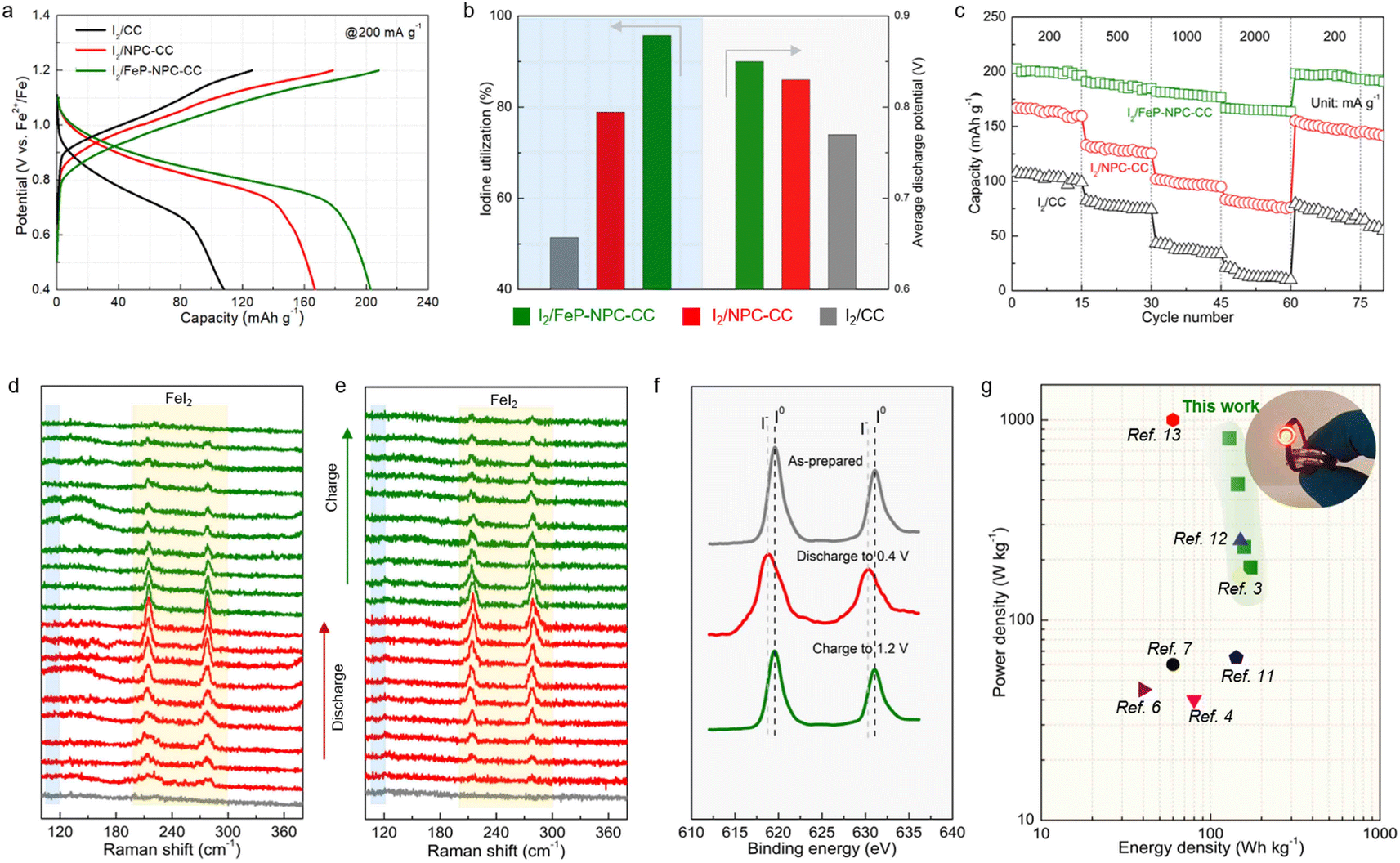 | ||
| Fig. 4 Mechanistic investigation of reversible iodine conversion. (a) Typical charge–discharge profiles and (b) comparison of iodine utilization and average discharge voltage of different cathodes as noted. (c) Comparison of rate performance for Fe–I2 cells using iodine cathodes supported by different matrices. In situ Raman spectra of (d) I2/FeP-NPC-CC and (e) I2/CC electrodes at different discharge/charge states. (f) Ex situ XPS spectra of I2/FeP-NPC-CC cathode at pristine and different charge/discharge states. (g) Ragone plot of our work compared to previously reported aqueous batteries; the inset shows an LED indicator (driving potential: 1.6 V) powered by parallel-connected I2/FeP-NPC-CC//Fe cells. | ||
We then employed in situ Raman spectroscopy to verify the iodine evolution pathway in the course of battery cycling for investigating the mechanism of the improvements in iodine redox kinetics enabled by the catalytic matrix. The series of Raman vibrational peaks are presented in Fig. 4d and e. For the I2/FeP-NPC-CC cathode, the characteristic peaks (at ∼214 cm−1 and ∼278 cm−1) associated with FeI2 gradually emerge and the intensity of these peaks kept increasing during discharge. It is noted that the characteristic peaks of FeI2 appear earlier and with higher intensity for I2/FeP-NPC-CC in contrast to I2/CC, revealing the origin of the prolonged discharge voltage plateau and increased potentials. Afterward, it is witnessed that the Raman spectral changes are then reversed upon charging as the FeI2 peaks continuously decreased. Compared with I2/FeP-NPC-CC, it can be observed that a trace of the characteristic FeI2 peaks still exists at the fully charged state for the I2/CC cathode, highlighting the importance of catalytic centers for reversible full iodine conversion. It also identifies that FeI2 decomposes more rapidly on I2/FeP-NPC-CC than on I2/CC, corresponding to the facile recharging process. Of note, the characteristic peaks of polyiodide intermediates (e.g., I3−) are absent during the whole battery cycle, indicating the one-step conversion mode of iodine in the Fe–I2 electrochemistry. Furthermore, ex situ XPS analysis confirmed the consistent trend of the reversible iodine conversion reactions with the same cycling. As shown in Fig. 4f, when the cathode was charged back to 1.2 V after one cycle, the I 3d peaks were similar to those of pristine iodine. All the above spectroscopic results suggest that the bidirectional catalysis facilitates the reversible iodine conversion during cycling.
Moreover, the energy density and power density of the presented I2/FeP-NPC-CC//Fe cell and of other reported aqueous ion batteries are plotted in Fig. 4g to further highlight the superiority of the one-step conversion Fe–I2 cell. The cell achieves a superior energy density of 172 W h kg−1 at 183 W kg−1 and a high power density of 809 W kg−1 at 129 W h kg−1 based on the cathode materials. The I2/FeP-NPC-CC//Fe cell still reaches a high energy density of 90 W h kg−1 at 156 W kg−1 when considering the total weight of cathode materials. The electrochemical performance is superior to those of reported battery systems.
Kinetic investigations on iodine redox reaction
The boosted iodine redox kinetics enabled by the FeP-NPC-CC host was directly reflected in the CV results. Fig. 5a compares the CV plots of three electrodes at a scanning rate of 0.05 mV s−1 ranging from 0.4 to 1.2 V. All CV curves show one redox peak pair at about 0.8/1.0 V, implying the one-step iodine redox conversion in the Fe–I2 electrochemistry. Moreover, in contrast to the I2/CC and I2/NPC-CC positive electrodes, the I2/FeP-NPC-CC cathode has the highest peak intensities and largest enclosed area, representing faster redox kinetics and higher ion storage capability. Additionally, the anodic–cathodic peak separations of the I2/FeP-NPC-CC electrode are the smallest compared with reference cathodes. The decreased overpotential indicates that iodine in the FeP-NPC-CC matrix presents an accelerated conversion rate owing to the bidirectional catalytic effect of the FeP-NPC catalyst. To further quantify the catalytic activity of the FeP-NPC-CC host, Tafel plots were calculated according to the corresponding CV profiles in Fig. 5a. Similarly, the I2/FeP-NPC-CC cathode shows the smallest Tafel slope compared with the cases of control electrodes, demonstrating the favorable reduction and oxidation of I2 within the FeP-NPC-CC framework. Note that the Tafel slope of FeI2 oxidation to I2 is strongly correlated with the FeP component (Fig. 5b), owing to the I2/FeP-NPC-CC cathode exhibiting a slope of 78 mV dec−1 whereas the slope for I2/CC is similar to that for I2/NPC-CC (129 and 119 mV dec−1, respectively). This reveals that the FeP hotspots play a key role in accelerating the conversion of FeI2 back to I2. Meanwhile, the cathodes with the NPC component exhibit smaller slopes of 31–28 mV dec−1, while the slope for I2/CC is 119 mV dec−1 (Fig. 5c). This difference implies that NPC sites could significantly catalyze the reduction of I2 to FeI2. As such, the above CV analysis reveals that the bidirectional catalytic activity of the FeP-NPC-CC matrix effectively triggers the promoted kinetics of round-trip redox reactions (I2 ↔ FeI2) in Fe–I2 batteries (Fig. 5d). In addition, potentiostatic discharge measurement was further conducted on FeP-NPC-CC, NPC-CC and CC following the same discharging step (Fig. S5†). Compared with the CC and NPC-CC electrodes, the FeP-NPC-CC electrode exhibits a higher current peak and realizes higher capacities of iodine precipitation, implying the effective promotion of iodine conversion on the FeP-NPC-CC catalytic matrix and in good agreement with the above conclusion.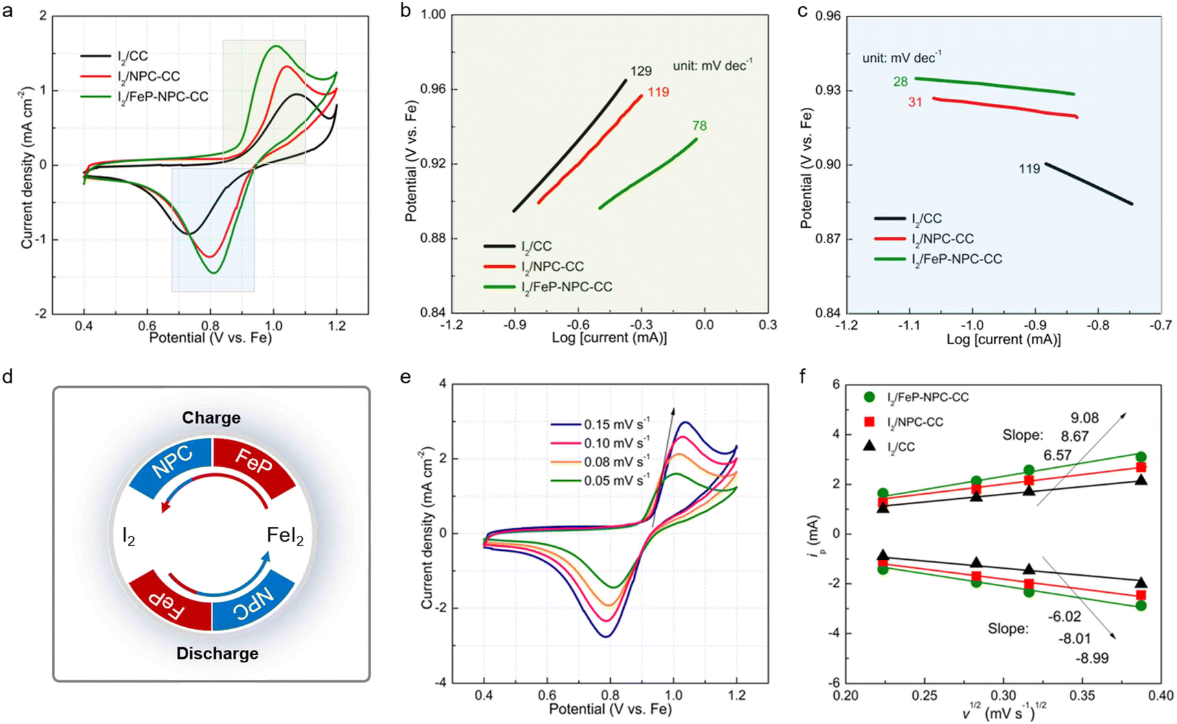 | ||
| Fig. 5 Kinetic analyses of bidirectional catalysis-facilitated iodine redox. (a) CV profiles of Fe–I2 coin cells assembled with different cathodes at a scan rate of 0.05 mV s−1. Tafel plots calculated from the peaks of (b) iodine oxidation and (c) reduction in (a). (d) Schematic diagram of the bidirectional catalysis-directed iodine redox reactions during battery cycling. (e) CV curves of I2/FeP-NPC-CC cathode at various scan rates. (f) Linear fitting of anodic and cathodic peaks versus square root of scan rate for different electrodes as noted. | ||
CV curves at different scan rates were recorded for investigating the origin of the improved redox kinetics. Fig. 5e displays the CV profiles of the I2/FeP-NPC-CC cathode at increasing sweep rates from 0.05 to 0.15 mV s−1. Moreover, there is a linear relationship with the square root of scanning rates for all electrodes, indicative of a diffusion-limited redox reaction. Therefore, the classical Randles–Sevcik equation can be employed to evaluate the Fe ion diffusion coefficient: Ip = (2.69 × 10⁵)n1.5ADFe2+0.5CFe2+ν0.5, where the Ip is the peak current, n is the number of electrons transferred in the redox reactions, CFe2+ is the Fe2+ concentration in the electrode, A is the effective surface area, D is the diffusion coefficient of Fe2+, and v is the scan rate.42–44 Accordingly, the slopes of reduction and oxidation peaks for I2/FeP-NPC-CC are higher than those for control electrodes (Fig. 5f), indicative of the fastest diffusion kinetics enabled by the bidirectional catalytic effects. Moreover, at a scan rate of 0.1 mV s−1, the calculated Fe ion diffusion coefficient is about 1.15 × 10⁻¹³ cm2 s−1 for I2/FeP-NPC-CC, which is higher than those for control electrodes (9.59 × 10⁻¹⁴ cm2 s−1 for I2/NPC-CC and 7.55 × 10⁻¹⁴ cm2 s−1 for I2/CC).
Degradation mechanism of Fe–I2 cells and electrochemical performance of the assembled pouch cell
Long-term cycling tests were conducted to further validate the electrochemical benefit of the catalytic matrix, as shown in Fig. 6a. Accordingly, I2/FeP-NPC-CC exhibited superior long-term cycling stability by allowing high capacity retention of 92% after 500 cycles at 500 mA g−1. In contrast, the control I2/CC and I2/NPC-CC cathodes have inferior capacity retention of 15% and 81%, respectively. It is notable that I2/FeP-NPC-CC could maintain a high average CE of 99.1% while the I2/CC and I2/NPC-CC electrodes exhibit a gradually decreasing average CE during battery dynamic cycling. This difference reveals that the functional matrix accelerates the bidirectional iodine redox kinetics, thereby enhancing the average CE and cycling stability. Moreover, the electrochemical performance of the I2/FeP-NPC-CC cathode is thus comparable to and even better than much of the reported results (Table S2†).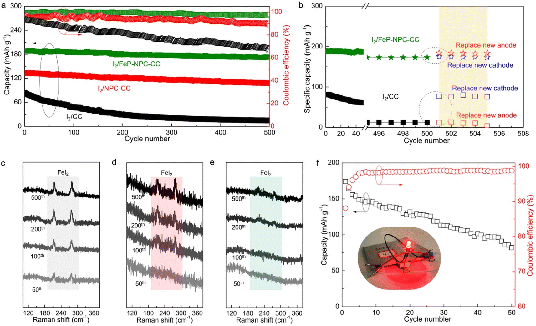 | ||
| Fig. 6 Investigation on the cell's degradation mechanism and electrochemical performance of I2/FeP-NPC-CC//Fe pouch cell. (a) Cycling stability of Fe–I2 coin cells assembled with different cathodes at a current density of 500 mA g−1. (b) The discharge capacity recovery of different Fe–I2 coin cells when replacing a new cathode or anode. Raman spectra of (c) I2/CC, (d) I2/NPC-CC, and (e) I2/FeP-NPC-CC cathodes at fully charged state after cycling test. (f) Cycling stability of as-prepared I2/FeP-NPC-CC//Fe pouch cell at 50 mA g−1 and its optical photograph (inset; driving potential of the LED indicator: 1.6 V). | ||
To reveal the degradation mechanism of the as-prepared Fe–I2 cells, the post-cycled cells were replaced with a new cathode or anode for further cycling tests. As shown in Fig. 6b, the capacity of the I2/FeP-NPC-CC//Fe cell can be recovered to 184 mA h g−1 (about 98% of the initial capacity) when replacing a new Fe foil, which is better than the capacity of the cell with a new cathode (175 mA h g−1). This result indicates that the capacity decay of the I2/FeP-NPC-CC//Fe cell is mainly ascribed to the depletion of the metal anode. For the I2/CC//Fe cell, the reversible capacity can be reverted to 95% and 15% of the initial capacity after being repaired with a new cathode or anode, indicating the limited reversibility of the I2/CC cathode. Postmortem Raman analysis was utilized to investigate the origin of limited reversibility for cathodes (Fig. 6c–e). Accordingly, it is identified that the gradually increased peak intensity of FeI2 for the I2/CC electrode as the battery cycles implies the accumulation of the inactive iodine component. With the introduction of catalytic active sites, the characteristic peaks of inactive FeI2 were gradually diminished. Especially, no obvious FeI2 peaks can be observed even after 500 cycles because of the presence of the FeP and NPC components. Thus, these results reveal that the degradation of the I2/CC//Fe cell originates from the limited reversibility of iodine redox conversion. This also emphasizes the importance of the bidirectional catalytic effect in directing efficient iodine redox reactions. Moreover, a pouch cell (5 × 5 cm2) was assembled using the I2/FeP-NPC-CC cathode to further demonstrate its practical applicability (Fig. 6f). The I2/FeP-NPC-CC//Fe cell could deliver a high reversible capacity of 174 mA h g−1 (the capacity can reach 5.8 mA h g−1 when considering the total weight of cathode material, anode material and electrolyte) with an energy density of 146 W h kgiodine−1 and stable operation over 50 cycles. And a red LED light could be powered by parallel-connected Fe–I2 pouch cells. These results strongly confirm the advantages of the I2/FeP-NPC-CC cathode for realizing an advanced Fe–I2 cell.
Conclusion
In summary, a core–shell structured cathode design, in which N, P dual heteroatoms and FeP nanocrystals were integrated into a carbon shell to achieve bidirectional catalysis, is proposed to accelerate the formation and decomposition of FeI2 during battery dynamic cycling. And a well-balanced iodine full reduction and FeI2 facile reoxidation were achieved within the bifunctional composite cathode. The doped heteroatoms (N and P) function better in directing the full iodine reduction and FeP facilitates the facile FeI2 reoxidation. Consequently, the optimized Fe–I2 cell exhibits a reversible capacity of 202 mA h g−1 and maintains a capacity retention of 92% over 500 cycles, obtaining a power density as high as 809 W kg−1 at 129 W h kg−1. Simultaneously, a 146 W h kgcathode−1 pouch cell is further demonstrated and stably operates over 50 cycles. As revealed by postmortem analysis, the degradation of Fe anodes leads to the capacity decay of the Fe–I2 cell rather than the accumulation of inactive iodine. This work provides a promising direction to facilitate iodine redox conversion in metal–iodine batteries.Data availability
Data available on request.Author contributions
K. L. conceived and designed the project. W. Z. and M. W. performed all experimental and mechanism studies and wrote the required scripts. All authors were involved in the analysis of the results and further editing and reviewing process.Conflicts of interest
The authors declare no competing financial interests.Acknowledgements
This work was financially supported by the Natural Scientific Foundation of China (22208335, 22109001), the Hefei National Laboratory for Physical Sciences at the Microscale (KF2020106), Anhui Provincial Natural Science Foundation (2108085QB58), and startup funds provided to K. L. from Anhui University.References
- L. S. Cao, D. Li, T. Pollard, T. Deng, B. Zhang, C. Y. Yang, L. Chen, J. Vatamanu, E. Y. Hu, M. J. Hourwitz, L. Ma, M. Ding, Q. Li, S. Y. Hou, K. Gaskell, J. T. Fourkas, X. Q. Yang, K. Xu, O. Borodin and C. S. Wang, Nat. Nanotechnol., 2021, 16, 902 CrossRef CAS PubMed.
- D. L. Chao, W. H. Zhou, F. X. Xie, C. Ye, H. Li, M. Jaroniec and S. Z. Qiao, Sci. Adv., 2020, 6, 19 Search PubMed.
- K. Lu, B. Song, Y. X. Zhang, H. Y. Ma and J. T. Zhang, J. Mater. Chem. A, 2017, 5, 23628–23633 RSC.
- Y. X. Zeng, X. F. Lu, S. L. Zhang, D. Y. Luan, S. Li and X. W. Lou, Angew. Chem., Int. Ed., 2021, 60, 22189–22194 CrossRef CAS PubMed.
- X. Y. Wu, A. Markir, Y. K. Xu, E. C. Hu, K. T. Dai, C. Zhang, W. Shin, D. P. Leonard, K. I. Kim and X. L. Ji, Adv. Energy Mater., 2019, 9, 6 Search PubMed.
- X. Y. Wu, A. Markir, Y. K. Xu, C. Zhang, D. P. Leonard, W. Shin and X. L. Ji, Adv. Funct. Mater., 2019, 29, 7 Search PubMed.
- Y. K. Xu, X. Y. Wu, S. K. Sandstrom, J. J. Hong, H. Jiang, X. Chen and X. L. Ji, Adv. Mater., 2021, 33, 7 Search PubMed.
- Q. Zhao, M. J. Zachman, W. I. Al Sadat, J. X. Zheng, L. F. Kourkoutis and L. Archer, Sci. Adv., 2018, 4, 7 Search PubMed.
- H. Lv, Z. Wei, C. Han, X. Yang, Z. Tang, Y. Zhang, C. Zhi and H. Li, Nat. Commun., 2023, 14, 3117 CrossRef CAS PubMed.
- H. Y. Shi, Y. Song, Z. M. Qin, C. C. Li, D. Guo, X. X. Liu and X. Q. Sun, Angew. Chem., Int. Ed., 2019, 58, 16057–16061 CrossRef CAS PubMed.
- K. Lu, H. Zhang, B. Song, W. Pan, H. Y. Ma and J. T. Zhang, Electrochim. Acta, 2019, 296, 755–761 CrossRef CAS.
- Q. Guo, H. Z. Wang, X. T. Sun, Y. N. Yang, N. Chen and L. T. Qu, ACS Mater. Lett., 2022, 4, 1872–1881 CrossRef CAS.
- H. Li, M. Q. Li, X. J. Zhou and T. Li, J. Power Sources, 2020, 449, 7 Search PubMed.
- K. Lu, H. Zhang, F. L. Ye, W. Luo, H. Y. Ma and Y. H. Huang, Energy Storage Mater., 2019, 16, 1–5 CrossRef.
- C. L. Wei, J. J. Song, Y. Wang, X. Tang and X. M. Liu, Adv. Funct. Mater., 2023, 20, 2304223 CrossRef.
- X. L. Li, M. Li, Z. D. Huang, G. J. Liang, Z. Chen, Q. Yang, Q. Huang and C. Y. Zhi, Energy Environ. Sci., 2021, 14, 407–413 RSC.
- C. Bai, H. J. Jin, Z. S. Gong, X. Z. Liu and Z. H. Yuan, Energy Storage Mater., 2020, 28, 247–254 CrossRef.
- J. Z. Ma, M. M. Liu, Y. L. He and J. T. Zhang, Angew. Chem., Int. Ed., 2021, 60, 12636–12647 CrossRef CAS PubMed.
- C. Prehal, H. Fitzek, G. Kothleitner, V. Presser, B. Gollas, S. A. Freunberger and Q. Abbas, Nat. Commun., 2020, 11, 10 CrossRef PubMed.
- H. Zhang, Z. T. Shang, S. Y. Gao, B. Song, W. L. Zhang, R. G. Cao, S. H. Jiao, Y. W. Cheng, Q. W. Chen and K. Lu, J. Mater. Chem. A, 2022, 10, 11325–11331 RSC.
- Z. G. Li, X. H. Wu, X. Y. Yu, S. Y. Zhou, Y. Qiao, H. S. Zhou and S. G. Sun, Nano Lett., 2022, 22, 2538–2546 CrossRef CAS PubMed.
- G. H. Chen, Y. H. Kang, H. Y. Yang, M. H. Zhang, J. Yang, Z. H. Lv, Q. L. Wu, P. X. Lin, Y. Yang and J. B. Zhao, Adv. Funct. Mater., 2023, 33, 9 Search PubMed.
- L. T. Ma, Y. R. Ying, S. M. Chen, Z. D. Huang, X. L. Li, H. T. Huang and C. Y. Zhi, Angew. Chem., Int. Ed., 2021, 60, 3791–3798 CrossRef CAS PubMed.
- X. L. Li, N. Li, Z. D. Huang, Z. Chen, G. J. Liang, Q. Yang, M. Li, Y. W. Zhao, L. T. Ma, B. B. Dong, Q. Huang, J. Fan and C. Y. Zhi, Adv. Mater., 2021, 33, 9 Search PubMed.
- T. T. Liu, H. J. Wang, C. J. Lei, Y. Mao, H. Q. Wang, X. He and X. Liang, Energy Storage Mater., 2022, 53, 544–551 CrossRef.
- X. L. Li, Y. L. Wang, J. F. Lu, S. M. Li, P. Li, Z. D. Huang, G. J. Liang, H. Y. He and C. Y. Zhi, Angew. Chem., Int. Ed., 2023, 62, e202310168 CrossRef CAS PubMed.
- X. Li, S. Wang, D. Zhang, P. Li, Z. Chen, A. Chen, Z. Huang, G. Liang, A. L. Rogach and C. Zhi, Adv. Mater., 2023, e2304557 CrossRef PubMed.
- Y. Tian, S. Chen, Y. He, Q. Chen, L. Zhang and J. Zhang, Nano Res. Energy, 2022, 1, e9120025 CrossRef.
- W. W. Zhang, M. L. Wang, J. K. Ma, H. Zhang, L. Fu, B. Song, S. T. Lu and K. Lu, Adv. Funct. Mater., 2023, 33, 9 Search PubMed.
- J. T. Zhang, Z. H. Zhao, Z. H. Xia and L. M. Dai, Nat. Nanotechnol., 2015, 10, 444–452 CrossRef CAS PubMed.
- T. Zhang, T. X. Yang, B. Li, S. H. Wei and W. Gao, Appl. Surf. Sci., 2022, 597, 9 Search PubMed.
- K. Lu, Z. Y. Hu, J. Z. Ma, H. Y. Ma, L. M. Dai and J. T. Zhang, Nat. Commun., 2017, 8, 10 CrossRef PubMed.
- Z. Cheng, H. Pan, F. Li, C. Duan, H. Liu, H. Y. Zhong, C. C. Sheng, G. J. Hou, P. He and H. S. Zhou, Nat. Commun., 2022, 13, 9 CrossRef PubMed.
- K. Li, Z. Y. Hu, J. Z. Ma, S. Chen, D. X. Mu and J. T. Zhang, Adv. Mater., 2019, 31, 9 Search PubMed.
- Z. M. Zheng, H. H. Wu, H. D. Liu, Q. B. Zhang, X. He, S. C. Yu, V. Petrova, J. Feng, R. Kostecki, P. Liu, D. L. Peng, M. L. Liu and M. S. Wang, ACS Nano, 2020, 14, 9545–9561 CrossRef CAS PubMed.
- S. J. Zhang, J. N. Hao, H. Li, P. F. Zhang, Z. W. Yin, Y. Y. Li, B. K. Zhang, Z. Lin and S. Z. Qiao, Adv. Mater., 2022, 34, 11 Search PubMed.
- L. Q. Zhang, M. J. Zhang, H. L. Guo, Z. H. Tian, L. F. Ge, G. J. He, J. J. Huang, J. T. Wang, T. X. Liu, I. P. Parkin and F. L. Lai, Adv. Sci., 2022, 9, 10 Search PubMed.
- C. Bai, F. S. Cai, L. C. Wang, S. Q. Guo, X. Z. Liu and Z. H. Yuan, Nano Res., 2018, 11, 3548–3554 CrossRef CAS.
- Y. Ji, J. P. Xie, Z. X. Shen, Y. Liu, Z. R. Wen, L. Luo and G. Hong, Adv. Funct. Mater., 2023, 33, 9 Search PubMed.
- S. B. Chai, J. J. Yao, Y. L. Wang, J. H. Zhu and J. Jiang, Chem. Eng. J., 2022, 439, 9 CrossRef.
- H. Zhang, B. Song, W. W. Zhang, B. W. An, L. Fu, S. T. Lu, Y. W. Cheng, Q. W. Chen and K. Lu, Angew. Chem., Int. Ed., 2023, 62, 10 Search PubMed.
- Y. P. Zou, T. T. Liu, Q. J. Du, Y. Y. Li, H. B. Yi, X. Zhou, Z. X. Li, L. J. Gao, L. Zhang and X. Liang, Nat. Commun., 2021, 12, 11 CrossRef PubMed.
- G. M. Zhou, H. Z. Tian, Y. Jin, X. Y. Tao, B. F. Liu, R. F. Zhang, Z. W. Seh, D. Zhuo, Y. Y. Liu, J. Sun, J. Zhao, C. X. Zu, D. S. Wu, Q. F. Zhang and Y. Cui, Proc. Natl. Acad. Sci. U. S. A., 2017, 114, 840–845 CrossRef CAS PubMed.
- Y. J. Li, J. B. Wu, B. Zhang, W. Y. Wang, G. Q. Zhang, Z. W. Seh, N. Zhang, J. Sun, L. Huang, J. J. Jiang, J. Zhou and Y. M. Sun, Energy Storage Mater., 2020, 30, 250–259 CrossRef.
Footnotes |
| † Electronic supplementary information (ESI) available. See DOI: https://doi.org/10.1039/d3sc04853e |
| ‡ W. Z. and M. W. contributed equally to this work. |
| This journal is © The Royal Society of Chemistry 2023 |