
 Open Access Article
 This Open Access Article is licensed under a Creative Commons Attribution-Non Commercial 3.0 Unported Licence
Stepwise assembly of thiacalix[4]arene-protected Ag/Ti bimetallic nanoclusters: accurate identification of catalytic Ag sites in CO2 electroreduction†
Yi-Qi
Tian
,
Wen-Lei
Mu
,
Lin-Lin
Wu
*,
Xiao-Yi
Yi
 ,
Jun
Yan
* and
Chao
Liu
*
,
Jun
Yan
* and
Chao
Liu
*
Hunan Provincial Key Laboratory of Chemical Power Sources, College of Chemistry and Chemical Engineering, Central South University, Changsha 410083, Hunan, P. R. China. E-mail: chaoliu@csu.edu.cn
First published on 5th September 2023
Abstract
The accurate identification of catalytic sites in heterogeneous catalysts poses a significant challenge due to the intricate nature of controlling interfacial chemistry at the molecular level. In this study, we introduce a novel strategy to address this issue by utilizing a thiacalix[4]arene (TC4A)-protected Ti-oxo core as a template for loading Ag1+ ions, leading to the successful synthesis of a unique Ag/Ti bimetallic nanocluster denoted as Ti8Ag8. This nanocluster exhibits multiple surface-exposed Ag sites and possesses a distinctive “core–shell” structure, consisting of a {Ti4@Ag8(TC4A)4} core housing a {Ti2O2@Ag4(TC4A)2} motif and two {Ti@Ag2(TC4A)} motifs. To enable a comprehensive analysis, we also prepared a Ti2Ag4 cluster with the same {Ti2O2@Ag4(TC4A)2} structure found within Ti8Ag8. The structural disparities between Ti8Ag8 and Ti2Ag4 provide an excellent platform for a comparison of catalytic activity at different Ag sites. Remarkably, Ti8Ag8 exhibits exceptional performance in the electroreduction of CO2 (eCO2RR), showcasing a CO faradaic efficiency (FECO) of 92.33% at −0.9 V vs. RHE, surpassing the FECO of Ti2Ag4 (69.87% at −0.9 V vs. RHE) by a significant margin. Through density functional theory (DFT) calculations, we unveil the catalytic mechanism and further discover that Ag active sites located at {Ti@Ag2(TC4A)} possess a higher εd value compared to those at {Ti2O2@Ag4(TC4A)2}, enhancing the stabilization of the *COOH intermediate during the eCO2RR. This study provides valuable insights into the accurate identification of catalytic sites in bimetallic nanoclusters and opens up promising avenues for efficient CO2 reduction catalyst design.
Introduction
The electrochemical CO2 reduction reaction (eCO2RR) offers a promising approach for the conversion of CO2 into valuable chemical fuels.1,2 Ag-based nanomaterials have gained significant attention as electrocatalysts for the eCO2RR, demonstrating remarkable selectivity towards CO generation.3–6 Despite substantial advancements in the synthesis of monodisperse Ag nanoparticles with enhanced catalytic activity, their surface structures remain challenging to precisely characterize and define.7,8 This limitation hinders the investigation of the structure–activity relationship. Consequently, it is crucial to attain synthetic control over the coordination environments of active Ag sites, enabling the creation of well-defined catalytic centers. Such control holds immense potential for elucidating the structure–activity relationship of Ag nanocatalysts, thereby facilitating efficient catalysis.In the realm of Ag catalysis, pre-transition metal oxides (e.g., TiO2) have gained significant prominence as substrates for the stabilization of Ag nanoparticles featuring surface-exposed catalytic sites.9–13 The interplay between the oxide substrate and the active metal site manifests unique physical properties, thus prompting extensive investigations into the structural characteristics and reactive models of Ag–TiO2 materials.14 By establishing a close association between titanium-oxo clusters (TOCs) and TiO2,15–24 Ag-doped TOCs can be considered as molecular counterparts of bulk Ag–TiO2 nanomaterials. Previous studies have successfully synthesized certain crystalline Ag–TOCs,25–31 although the Ag sites were predominantly embedded within the TOCs as single atoms or clusters, impeding direct interaction with the reactants. Consequently, the controlled assembly of Ag–TOCs featuring surface-exposed Ag catalytic sites and the precise identification of their catalytic centers have posed significant challenges. Regarding the cluster assembly, ligands are the most important prerequisites that we should consider. Thiacalix[4]arene, a macrocyclic compound featuring four phenol units bridged by four S-groups, has caught our attention, the oligomers of which are favourable to form typical tetranuclear M4-TC4A units to fabricate high-nuclearity clusters.32–37 According to soft and hard acid/base theory, the Ti4+ ion is a hard Lewis acid with a strong coordination affinity for phenolic oxygen, while Ag1+ is a soft Lewis acid that exhibits an affinity for soft bases, such as the S atom. It has here been assumed that if O-philic Ti4+ and S-philic Ag1+ ions participate in an assembly with TC4A, it would result in unexplored bimetallic clusters with unique geometric and/or electronic structures. Despite the existence of TC4A-protected TOCs38–40 and Ag nanoclusters,41–46 the synthesis of TC4A-stabilized Ag/Ti bimetallic clusters has yet to be reported in the literature.
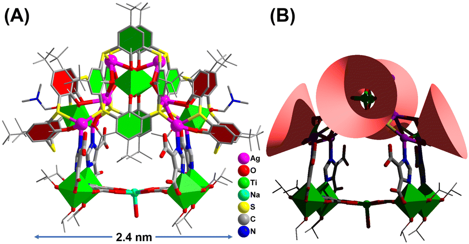
Herein we provide a cluster model to accurately identify the Ag catalytic sites in CO2 electroreduction. Through the synergistic assembly of TC4A and 4,5-imidazoledicarboxylic acid (IdcH2), we synthesized the first calixarene-protected Ag1+/Ti4+ bimetallic cluster of Ti8Ag8 with the formula of [HNaTi8Ag8O2(TC4A)4(HIdc)6(iPrO)10(DMF)2(H2O)] (Fig. 1). The big cluster has a composite structure with two kinds of surface-exposed Ag sites, including the Ag(I) sites in the two {Ti@Ag2(TC4A)} and the Ag(II) sites in the {Ti2O2@Ag4(TC4A)2} units. We have carefully studied the formation path of Ti8Ag8 and crystallized four structural intermediates, Ti1Ag1, Ti2Ag2, Ti2Ag2.6 and Ti2Ag4, by controlling synthesis conditions. Interestingly, Ti2Ag4 was exactly identical to the {Ti2O2@Ag4(TC4A)2} unit in Ti8Ag8, thus providing a perfect cluster model for comparing the catalytic activity of different Ag sites. The Ti8Ag8 cluster was found to be an excellent eCO2RR catalyst, which exhibited high reactivity and selectivity to CO (92.33% FE at −0.9 V vs. RHE), outperforming Ti2Ag4. The DFT method was used to calculate the free energy change of each elementary step in the conversion mechanism from CO2 to CO, and in the competing hydrogen evolution reaction (HER). It was demonstrated that the Ag centers located on {Ti@Ag2(TC4A)} could stabilize the *COOH intermediates in the CO2 electroreduction better than those located on {Ti2O2@Ag4(TC4A)2}.
 | ||
| Fig. 1 Single-crystal X-ray structure of Ti8Ag8. | ||
Results and discussion
Synthesis and characterization
The synthesis of Ti8Ag8 was accomplished through a one-pot solvothermal reaction using Ag(O2CCF3), Ti(OiPr)4, TC4A, and IdcH2 in a 2 mL solution of iPrOH/DMF (v/v = 1![[thin space (1/6-em)]](https://www.rsc.org/images/entities/char_2009.gif) :2) at 80 °C for 2 days. This reaction yielded yellow prismatic crystals with a high yield of 60%. The composition of Ti8Ag8 was determined using electrospray ionization-mass spectrometry (ESI-MS), which revealed a +2 signal at m/z = 2663.46, corresponding to the species [H3NaTi8Ag8O2(TC4A)4(Idc)6(iPrO)4]2+ (Fig. S33†). The molar ratio of Ti:Ag:Na in Ti8Ag8 was determined through inductively coupled plasma (ICP) analysis (Table S2†), yielding a ratio of approximately 8:8:1, which is consistent with the findings from crystallography analysis. The geometrical structure of Ti8Ag8 was found to be rather complicated, resembling a “hand basket”, which can be divided into two parts. The handle of the basket is composed of a core–shell {Ti4@Ag8@(TC4A)4} substructure (Fig. 2A), while the bottom of the basket is formed by one {Ti4Na(Idc)6} substructure (Fig. 2B). The {Ti4@Ag8(TC4A)4} substructure can be further divided into two {Ti@Ag2(TC4A)} motifs (Fig. 2C) and one {Ti2O2@Ag4(TC4A)2} motif (Fig. 2D). Upon inspecting the structure of {Ti2O2@Ag4(TC4A)2}, it was observed that each of the two completely deprotonated TC4A molecules accommodated an apical Ti4+ ion within their lower-rim tetraphenolic pocket, which are further fused together through two μ2-O2− to form {Ti2O2@(TC4A)2} units. Additionally, the two Ti4+ ions inside the cage exhibited octahedral TiO6 formations. The Ag4 array sandwiched between two calix entities formed a trapezium-like geometry. Among them, two exposed Ag(I) sites (Ag1 and Ag2) were located in an O3S2 environment defined by two phenoxide, one μ2-O2−, and two S (Ag–S: 2.558(2)–2.589(2) Å and Ag–O: 2.499(2)–2.645(2) Å), while the Ag3 and Ag4 sites were fully coordinated and embedded within the cluster. In the {Ti@Ag2(TC4A)} unit, TC4A accommodated the apical Ti4+ ion within its lower-rim tetraphenolic pocket, with two of the four S arms bridging to two Ag1+ ions. The four equivalent Ag(II) sites (Ag5–Ag8) were in an O2S2N environment defined by two phenoxide (Ag–O: 2.696(9)–2.894(2) Å), two S (Ag–S: 2.487(2)–2.573(8) Å), and one imidazole N. The Ag–O bonds were relatively long, suggesting weaker interactions. One {Ti2O2@Ag4(TC4A)2} and two {Ti@Ag2@TC4A} units were coupled together through four Ag–S bonds and six Ag–O bonds to form the {Ti4@Ag8@(TC4A)4} substructure. In the {Ti4Na(Idc)6} substructure, the two Idc ligands at the bottom each bridged two Ti4+ ions to form two {Ti2(Idc)} units, which were further bridged by a Na+ ion to create a planar {Ti4Na(Idc)2} layer. The other four protonated Idc ligands acted as bridges between the {Ti@Ag2TC4A} and {Ti4Na(Idc)2} units. In this way, the two substructures of {Ti4@Ag8(TC4A)4} and {Ti4Na(Idc)6} were joined together by four Ag–N bonds (Ag–N: 2.220(5)–2.246(2) Å) to form the final Ti8Ag8 cluster.
:2) at 80 °C for 2 days. This reaction yielded yellow prismatic crystals with a high yield of 60%. The composition of Ti8Ag8 was determined using electrospray ionization-mass spectrometry (ESI-MS), which revealed a +2 signal at m/z = 2663.46, corresponding to the species [H3NaTi8Ag8O2(TC4A)4(Idc)6(iPrO)4]2+ (Fig. S33†). The molar ratio of Ti:Ag:Na in Ti8Ag8 was determined through inductively coupled plasma (ICP) analysis (Table S2†), yielding a ratio of approximately 8:8:1, which is consistent with the findings from crystallography analysis. The geometrical structure of Ti8Ag8 was found to be rather complicated, resembling a “hand basket”, which can be divided into two parts. The handle of the basket is composed of a core–shell {Ti4@Ag8@(TC4A)4} substructure (Fig. 2A), while the bottom of the basket is formed by one {Ti4Na(Idc)6} substructure (Fig. 2B). The {Ti4@Ag8(TC4A)4} substructure can be further divided into two {Ti@Ag2(TC4A)} motifs (Fig. 2C) and one {Ti2O2@Ag4(TC4A)2} motif (Fig. 2D). Upon inspecting the structure of {Ti2O2@Ag4(TC4A)2}, it was observed that each of the two completely deprotonated TC4A molecules accommodated an apical Ti4+ ion within their lower-rim tetraphenolic pocket, which are further fused together through two μ2-O2− to form {Ti2O2@(TC4A)2} units. Additionally, the two Ti4+ ions inside the cage exhibited octahedral TiO6 formations. The Ag4 array sandwiched between two calix entities formed a trapezium-like geometry. Among them, two exposed Ag(I) sites (Ag1 and Ag2) were located in an O3S2 environment defined by two phenoxide, one μ2-O2−, and two S (Ag–S: 2.558(2)–2.589(2) Å and Ag–O: 2.499(2)–2.645(2) Å), while the Ag3 and Ag4 sites were fully coordinated and embedded within the cluster. In the {Ti@Ag2(TC4A)} unit, TC4A accommodated the apical Ti4+ ion within its lower-rim tetraphenolic pocket, with two of the four S arms bridging to two Ag1+ ions. The four equivalent Ag(II) sites (Ag5–Ag8) were in an O2S2N environment defined by two phenoxide (Ag–O: 2.696(9)–2.894(2) Å), two S (Ag–S: 2.487(2)–2.573(8) Å), and one imidazole N. The Ag–O bonds were relatively long, suggesting weaker interactions. One {Ti2O2@Ag4(TC4A)2} and two {Ti@Ag2@TC4A} units were coupled together through four Ag–S bonds and six Ag–O bonds to form the {Ti4@Ag8@(TC4A)4} substructure. In the {Ti4Na(Idc)6} substructure, the two Idc ligands at the bottom each bridged two Ti4+ ions to form two {Ti2(Idc)} units, which were further bridged by a Na+ ion to create a planar {Ti4Na(Idc)2} layer. The other four protonated Idc ligands acted as bridges between the {Ti@Ag2TC4A} and {Ti4Na(Idc)2} units. In this way, the two substructures of {Ti4@Ag8(TC4A)4} and {Ti4Na(Idc)6} were joined together by four Ag–N bonds (Ag–N: 2.220(5)–2.246(2) Å) to form the final Ti8Ag8 cluster.
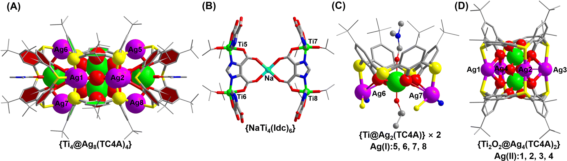 | ||
| Fig. 2 Detailed local structures of {Ti4@Ag8(TC4A)4} (A), {Ti4Na(Idc)6} (B), {Ti@Ag2(TC4A)} (C) and {Ti2O2@Ag4(TC4A)2} (D). | ||
Tracking of the assembly process of Ti8Ag8
To understand the formation of Ti8Ag8, tracking its evolution process by mass spectrometry was performed. Firstly, the structural formation could be conveniently probed by matrix-assisted laser desorption/ionization time-of-flight mass spectrometry (MALDI-TOF-MS) of the crystalline samples of Ti8Ag8 in the positive mode, using CH2Cl2 as a solvent (Fig. 3A). The pattern showed abundant fragment signals. The most dominant m/z peak at 1993.7 was attributed to the [HTi2Ag4O2(TC4A)2]1+ species, which corresponded to the {Ti2O2@Ag4(TC4A)2} unit in Ti8Ag8. Interestingly, this intermediate could be crystallized and structurally resolved. The Ti2Ag4 cluster was synthesized by the reaction of TC4A and Ag(OAc) with Ti(OiPr)4 in CH3CN/DMF. Structure determination revealed that the structure of Ti2Ag4 was exactly the same as that of the {Ti2O2@Ag4(TC4A)2} unit in Ti8Ag8. This “core–shell” structure had a high chemical stability. One can see that only a peak corresponding to [HTi2Ag4O2(TC4A)2]1+ was observed in the MALDI-TOF-MS of Ti2Ag4 in CH2Cl2, indicating that the cluster retained its integrity in solution (Fig. S35†). However, under the hard ionization conditions of ESI-MS, the pattern of Ti2Ag4 showed an abundance of cluster fragments (Fig. 3B). Signals corresponding to the units of {Ti2@Ag4-x(TC4A)2} (x = 0–4) can be found, which indicated that the four Ag1+ ions in Ti2Ag4 could be gradually dropped. The removal of Ag1+ ions indicated that the Ti2Ag4 cluster originated from the {Ti2O2@(TC4A)2} unit, whose surface abundance of S/O sites provided binding sites for the Ag1+ ions. The crystallography data of structural intermediates Ti1Ag1, Ti2Ag2, and Ti2Ag2.6 help us precisely determine the structural model of the product generated upon fragmentation. These intermediates were all crystallized in the same system by a slight change in the reaction conditions. For Ti1Ag1, the TC4A unit kept one Ti4+ ion within the bowl, with one S arm binding to one Ag(PPh3)2 unit. For Ti2Ag2, two {Ti@TC4A} units were bridged by one μ2-O2− ion and two Ag1+ ions, forming an asymmetrical semi-closed cage. Ti2Ag2.6 also contained a {Ti2O@(TC4A)2} core, with a total number of 2.6 Ag1+ ions embedded in the waist in a disordered manner.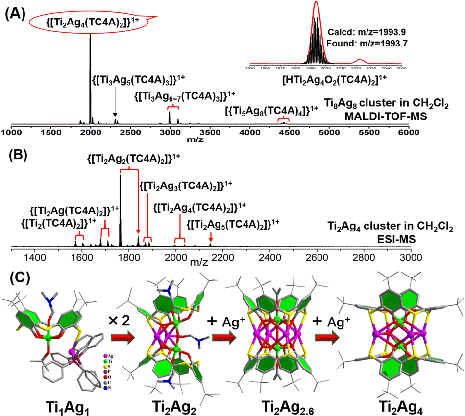 | ||
| Fig. 3 (A) Positive-ion mode MALDI-TOF-MS of Ti8Ag8 dissolved in CH2Cl2. Inset: zoomed-in experimental and simulated ESI-MS of [HTi2Ag4O2(TC4A)2]1+; (B) positive-ion mode ESI-MS of Ti2Ag4 dissolved in CH2Cl2. (C) Structures of the TiAg, Ti2Ag2, Ti2Ag2.6 and Ti2Ag4 clusters. | ||
In the ESI-MS of Ti2Ag4, a distinctive signal corresponding to [Na2Ti2Ag5O2(TC4A)2]1+ was observed. This signal was formed by the binding of Ag1+ to the {Ti2O2@Ag4(TC4A)2} core, suggesting that the {Ti2O2@Ag4(TC4A)2} could serve as a seed for further growth. The primary question at this point was whether {Ti2O2@Ag4(TC4A)2} could be further transformed into Ti8Ag8. Remarkably, the crystal of Ti8Ag8 can be directly obtained from the solvothermal reaction of Ti2Ag4, Ti(OiPr)4, and IdcH2 in iPrOH/DMF at 80 °C for 2 days. Fig. 4 illustrates the time-dependent ESI-MS analysis of the mother liquor at different time intervals during the reaction. In the initial stage, the signals in the low m/z region closely resembled those observed in the ESI-MS of Ti2Ag4. However, as the reaction progressed, new signals emerged in the high m/z region. Specifically, peaks corresponding to the units of [H3NaTi3Ag8O2(TC4A)3(Idc)(iPrO)2(DMF)2]+ (m/z = 3633.70) and [HTi4Ag8O2(TC4A)4(OH)2]+ (m/z = 3988.76) were detected at 4 hours and 8 hours, respectively. These fragments can be regarded as a combination of one {Ti2O2@Ag4(TC4A)2} unit and one or two {Ti@Ag2(TC4A)} units. At the 24 hour mark, a +2 peak of [H3NaTi6Ag8O2(TC4A)4(HIdc)5(iPrO)3]2+ (m/z = 2500.30) was observed, which is formed by the {Ti4@Ag8(TC4A)4} substructure bridging Ti4+ with Idc ligands. After 48 hours of reaction, the ESI-MS results of the mother liquid exhibited a series of +2 peaks within the m/z range of 2600–2900. Among them, the prominent peaks at 1 g and 1 h were assigned to [H3Na2Ti8Ag8O2(TC4A)4(Idc)6(iPrO)5(H2O)2]2+ and [H4NaTi8Ag8O2(TC4A)4(Idc)6(iPrO)6(H2O)]2+, respectively, confirming the formation of the Ti8Ag8 cluster. These findings clearly demonstrated that Ti8Ag8 could be derived from the {Ti2O2@Ag4(TC4A)2} unit, following a small-to-large assembly pathway.
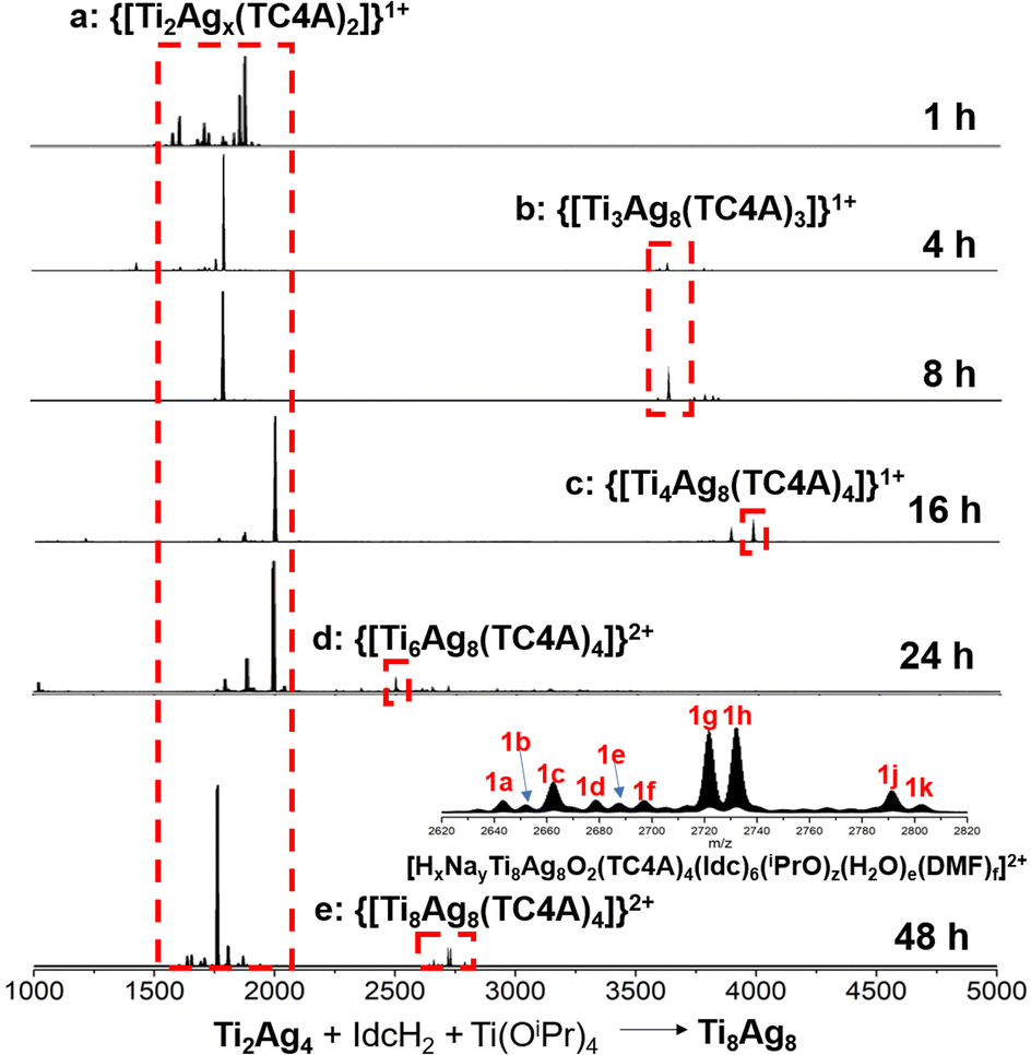 | ||
| Fig. 4 Time-dependent ESI-MS in the range of m/z 1000–5000 for the reaction of Ti2Ag4, Ti(OiPr)4 and IdcH2 in iPrOH/DMF at 80 °C at 1 h, 4 h, 8 h, 16 h, 24 h and 48 h. | ||
Thus, with the aid of the crystal structures of intermediate clusters, cluster fragment information, and growth paths revealed by time-dependent mass spectrometry, a comprehensive bottom-up evolution route for this series of TC4A-protected Ag/Ti bimetallic nanoclusters can be presented (Fig. S13†). In the initial stage, TC4A captures Ti4+ ions, leading to the formation of TOCs such as {Ti@(TC4A)} and {Ti2O2@(TC4A)2}. The abundance of S/O sites on these TOCs enables them to act as substrates for the adsorption of Ag1+ ions, giving rise to the clusters of Ti1Ag1, Ti2Ag2, Ti2Ag2.6 and Ti2Ag4. These structures can be separated through crystallization under different conditions. Moving forward, the {Ti@Ag2(TC4A)} and {Ti2O2@Ag4(TC4A)2} units combine to form {Ti3@Ag6(TC4A)3} and {Ti4@Ag8(TC4A)4}. Subsequently, Ti4+ ions are bridged to the {Ti4@Ag8(TC4A)4} substructure by the Idc2− ligands, culminating in the formation of the final Ti8Ag8 cluster.
Electrochemical CO2 reduction
Generally, the coordination and geometry environments to the Ag sites in Ag-based catalysts have an important effect on their catalytic activity. However, due to the lack of structural models, accurately comparing the catalytic activity of different Ag sites at the molecular level proves to be challenging. Upon detailed comparison of the XPS data for the clusters of Ti2Ag4 and Ti8Ag8, we observed a slight difference in the binding energies of the Ag species between them, with the binding energy of Ag in Ti2Ag4 approximately 0.1 eV lower compared to that of Ag in Ti8Ag8 (Fig. S26 and S27†). The subtle differences in their binding energies indicate variations in the local electronic structure and bonding characteristics between Ti2Ag4 and Ti8Ag8. Geometrically, the active Ag atoms in Ti8Ag8 could be divided into two nonequivalent groups: the four Ag(I) sites in two {Ti@Ag2(TC4A)} and the two exposed Ag(II) sites in {Ti2O2@Ag4(TC4A)2}. The structural differences between Ti8Ag8 and Ti2Ag4 provided an ideal platform for an accurate comparison of eCO2RR activities for those Ag sites.The eCO2RR activities of the Ti8Ag8 and Ti2Ag4 electrocatalysts were examined in a standard three-electrode configured H-type electrolytic cell with a 0.5 M KHCO3 electrolyte. Linear sweep voltammetry (LSV) studies showed that Ti8Ag8 exhibited a much higher current density and a more positive onset potential in a CO2 flow electrolyzer, as compared with an Ar purged one, indicating that Ti8Ag8 had CO2 reduction activity (Fig. 5A). The cyclic voltammetry (CV) studies of Ti8Ag8 in a proton-deficient organic solution showed similar results (Fig. S41†). For comparison, the LSV of Ti2Ag4 exhibits much lower current density. Fig. 5B compares the FE of the CO formation for the two clusters. Only CO and H2 were detected by gas chromatography. No other liquid product had been formed according to the 1H NMR spectra. Ti8Ag8 exhibited a higher FECO than Ti2Ag4 over the selected potential range from −0.6 V to −1.2 V. It achieved the maximum FECO of 92.33% at −0.9 V, which was much higher than the corresponding value of 69.87% for Ti2Ag4. The CO partial current density (JCO) for the two clusters was also calculated (Fig. 5C), and the JCO of Ti8Ag8 reached 23.46 mA cm−2 at −1.2 V vs. RHE, which was at least 2.5 times larger than that of Ti2Ag4 (9.50 mA cm−2). This indicates an improved catalytic activity and selectivity of Ti8Ag8 for the electrocatalytic CO2RR.
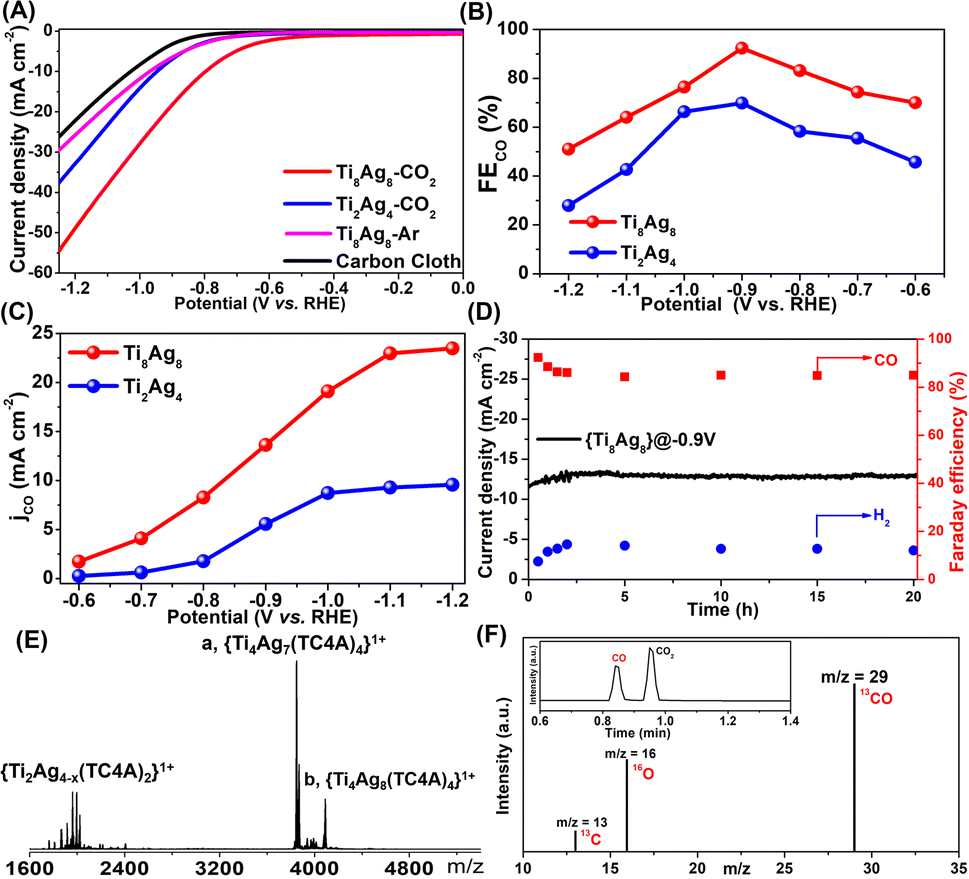 | ||
| Fig. 5 (A) LSV curves in CO2-saturated 0.5 M KHCO3 solution; (B) the FECO values at different applied potentials in CO2-saturated 0.5 M KHCO3 solution; (C) the CO partial current density (JCO); (D) stability tests of the electrocatalysts for CO2 reduction; (E) ESI-MS of Ti8Ag8 electrocatalysts after reaction; (F) GC-MS of 13CO recorded under a 13CO2 atmosphere. | ||
To find the underlying reasons for the performance differences between the two clusters, the Tafel slope was used to characterize their reaction kinetics in the electrolyte. The Tafel slope of Ti8Ag8 was found to be smaller than that of Ti2Ag4, indicating that Ti8Ag8 had more favorable reaction kinetics of CO formation, which may be due to the more efficient charge transfer and larger active surface of Ti8Ag8 during the catalytic process (Fig. S45†). To verify this, the electrochemically active surface area (ECSA) was characterized (Fig. S46†). By plotting ΔJ/2 = (Ja − Jc)/2 at −0.12 V vs. RHE against the scan rate, the calculated electrochemical Cdl of Ti8Ag8 is 6.18 mF cm−2, higher than that of Ti2Ag4 (5.54 mF cm−2), which indicated that Ti8Ag8 had a faster reaction speed in the CO2RR process and had more active sites to contact with electrolyte.
The electrochemical stability of Ti8Ag8 was evaluated with chronopotentiometry at −0.9 V vs. RHE. The current density and FECO kept almost stable during 20 h continuous electrolysis, indicative of the excellent reaction stability of Ti8Ag8 (Fig. 5D). We also recovered the catalyst after the reaction and conducted ESI-MS measurements. The ESI-MS pattern showed two strong signals that corresponded to [HTi4Ag8O2(TC4A)4(iPrO)2(H2O)]1+ and [H2Ti4Ag7O2(TC4A)4]1+. This indicated that the core structure of {Ti4@Ag8(TC4A)4} was still stable (Fig. 5E). Additionally, EDS analysis of the catalyst after the reaction indicated that the Ti and Ag elements remained in a 1:1 ratio (Fig. S50†). XPS analysis showed no significant change in the binding energy of the Ag element in the catalyst before and after the reaction, signifying the preservation of its coordination environment (Fig. S51†). Transmission electron microscopy (TEM) revealed the presence of clusters in the solution as discrete particles, with an average particle size of approximately 3 nanometers, consistent with the cluster size measured by SCXRD, further confirming the stability of the catalyst (Fig. S52†). To further determine the C origin of the products, an isotopic experiment was performed under similar catalytic conditions, but by using 13CO2 as the C source. The production of 13CO (m/z = 29) was then studied by using GC-MS, which showed that the generated CO came from CO2 (Fig. 5F).
DFT calculations were performed to investigate the reactivity of the two clusters. The calculation models, Ti4Ag8_m and Ti2Ag4_m, were optimized based on the crystal structures, by simplifying tBu groups of benzene rings to H atoms and iPrO groups to MeO groups. In addition, the Ti4Na(Idc)6 groups in Ti8Ag8 were removed to create active sites to build Ti4Ag8_m. The Gibbs free energy diagrams of the CO2RR and HER are shown in Fig. 6. The proposed pathway for the CO2 reduction to CO was CO2(g) → *COOH → *CO → CO(g). The calculated Gibbs free energies of the CO2RR revealed that the formation of *COOH was the rate determining step. The Gibbs free energy that was calculated for the formation of *COOH on the Ag site on the {Ti@Ag2(TC4A)} unit in Ti4Ag8_m was 1.01 eV, which was much lower than the corresponding Gibbs free energy for the {Ti@Ag2(TC4A)} unit in Ti2Ag4_m (1.42 eV). This result suggested that the Ag sites on {Ti@Ag2(TC4A)} were more energetically favorable for the catalysis of the CO2 conversion to CO than those on {Ti2O2@Ag4(TC4A)2}. The Gibbs free energies of the adsorptions were also calculated to illustrate the HER reactivities of Ti8Ag8 and Ti2Ag4. The high Gibbs free energies of the H* adsorption revealed that both Ti8Ag8 (1.63 eV) and Ti2Ag4 (2.00 eV) were unfavorable in the formation of H2. By comparing the Gibbs free energy diagrams of the CO2RR and HER, we found that Ti4Ag8_m had a higher selectivity for the CO formation, as compared with Ti2Ag4_m.
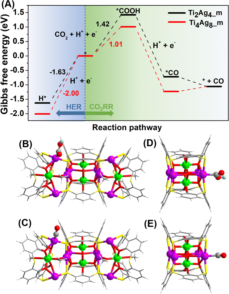 | ||
| Fig. 6 (A) Free energy diagrams for the CO2RR and HER on Ti4Ag8_m (red) and Ti2Ag4_m (black); the calculation optimized structures of COOH absorbed on Ti4Ag8_m (B) and Ti2Ag4_m (C); the calculation optimized structures of CO absorbed on Ti4Ag8_m (D) and Ti2Ag4_m (E). | ||
To further unravel the mystery of the differences in catalytic performances, the d-band center (εd) of the Ag sites in Ti4Ag8_m and Ti2Ag4_m was calculated to evaluate their reactivity as active sites, since εd has been proposed as a benchmark descriptor for transition metal reactivity.47 Our calculations showed markedly different electronic properties for the two nonequivalent Ag sites (Fig. S53†). In Ti4Ag8_m, the εd value of the four Ag(I) sites in {Ti@Ag2(TC4A)} is −0.34 eV, which is 0.06 eV higher than that of the two surface-exposed Ag(II) sites in {Ti2O2@Ag4(TC4A)2}. As a comparison, the four Ag(II) sites in Ti2Ag4_m also exhibit a lower εd value of −0.44 eV, suggesting that the Ag(I) sites in {Ti@Ag2(TC4A)} are more active than Ag(II) in the {Ti2O2@Ag4(TC4A)2} unit. Furthermore, the projected density of states (PDOS) showed that the active Ag(I) sites in Ti4Ag8_m underwent a stronger hybridization with the absorbed COOH and CO than those in Ti2Ag4_m (Fig. S55†). It is important to stress that the results from the DFT calculations were consistent with the corresponding experimental results. The combined theoretical and experimental investigations have thereby resulted in a fundamental understanding of the CO2RR mechanism involving different Ag active sites on the Ag/Ti bimetallic clusters.
Conclusions
In summary, we have for the first time compared eCO2RR atomic-level activities for different Ag sites on Ag-based catalysts. We synthesized and characterized an atomically precise bimetallic Ti8Ag8 cluster using a calixarene-protected Ti-oxo core as a substrate for loading Ag1+ ions. The Ti8Ag8 clusters contain two groups of surface-exposed Ag catalytic sites, located on the {Ti2O2@Ag4(TC4A)2} and {Ti@Ag2(TC4A)} units, respectively. We traced the assembly path of Ti8Ag8 and successfully isolated {Ti2O2@Ag4(TC4A)2} in the Ti2Ag4 cluster alone. The eCO2RR test showed that both clusters were good electrocatalysts for the reduction of CO2 to CO, but the performance of Ti8Ag8 was significantly superior to that of Ti2Ag4. Also, DFT was used to calculate the free energy change of each elementary step for converting CO2 into CO and the competing HER, revealing the difference in activity between the Ag sites on the {Ti@Ag2(TC4A)} and {Ti2O2@Ag4(TC4A)2} units. This work clearly demonstrated that subtle changes in the coordination geometry of catalytic sites can greatly affect the catalytic performance; thus, the attainment of the atomic structures of nanoclusters is of critical importance, which could provide a valuable reference for rational design of cluster structures to achieve efficient catalysis.Data availability
The data that support the findings of this study are available in the main text and the ESI.†Author contributions
C. L. and J. Y. supervised the project and conceived the idea. Y. Q. T. carried out synthesis, characterization and electrochemical experiments of clusters. C. L. and Y. Q. T. wrote the manuscript. L. L. W. undertook the calculations for this article. All authors discussed the experimental results.Conflicts of interest
There are no conflicts of interest to declare.Acknowledgements
This work was supported by the Natural Science Foundation of Hunan Province (2023JJ30650), the Central South University Innovation-Driven Research Programme (2023CXQD061) and the Fundamental Research Funds for the Central Universities of Central South University (2022ZZTS0527). We are grateful for resources from the High-Performance Computing Center of Central South University.Notes and references
- J. A. Turner, Science, 1999, 285, 687–689 CrossRef CAS PubMed.
- P. De Luna, C. Hahn, D. Higgins, S. A. Jaffer, T. F. Jaramillo and E. H. Sargent, Science, 2019, 364, 350–359 CrossRef PubMed.
- G. Wang, J. Chen, Y. Ding, P. Cai, L. Yi, Y. Li, C. Tu, Y. Hou, Z. Wen and L. Dai, Chem. Soc. Rev., 2021, 50, 4993–5061 RSC.
- L. Qin, F. Sun, X. Ma, G. Ma, Y. Tang, L. Wang, Q. Tang, R. Jin and Z. Tang, Angew. Chem., Int. Ed., 2021, 60, 26136–26141 CrossRef CAS PubMed.
- J. Y. Xu, L. Xiong, X. Cai, S. S. Tang, A. C. Tang, X. Liu, Y. Pei and Y. Zhu, Chem. Sci., 2022, 13, 2778–2782 RSC.
- J. Wang, F. Xu, Z.-Y. Wang, S.-Q. Zang and T. C. W. Mak, Angew. Chem., Int. Ed., 2022, 61, e202207492 CrossRef CAS PubMed.
- I. Chakraborty and T. Pradeep, Chem. Rev., 2017, 117, 8208–8271 CrossRef CAS PubMed.
- R. Jin, C. Zeng, M. Zhou and Y. Chen, Chem. Rev., 2016, 116, 10346–10413 CrossRef CAS PubMed.
- P. Liu, Y. Zhao, R. Qin, S. Mo, G. Chen, L. Gu, D. M. Chevrier, P. Zhang, Q. Guo, D. Zang, B. Wu, G. Fu and N. Zheng, Science, 2016, 352, 797–800 CrossRef CAS PubMed.
- J. Wan, W. Chen, C. Jia, L. Zheng, J. Dong, X. Zheng, Y. Wang, W. Yan, C. Chen, Q. Peng, D. Wang and Y. Li, Adv. Mater., 2018, 30, 1705369 CrossRef PubMed.
- L. DeRita, S. Dai, K. L. Zepeda, N. Pham, G. W. Graham, X. Pan and P. Christopher, J. Am. Chem. Soc., 2017, 139, 14150–14165 CrossRef CAS PubMed.
- H. Guan, J. Lin, B. Qiao, X. Yang, L. Li, S. Miao, J. Liu, A. Wang, X. Wang and T. Zhang, Angew. Chem., Int. Ed., 2016, 55, 2820–2824 CrossRef CAS PubMed.
- W. N. Wang, W. J. An, B. Ramalingam, S. Mukherjee, D. M. Niedzwiedzki, S. Gangopadhyay and P. Biswas, J. Am. Chem. Soc., 2012, 134, 11276–11281 CrossRef CAS PubMed.
- S. Chen, Z. N. Chen, W. H. Fang, W. Zhuang, L. Zhang and J. Zhang, Angew. Chem., Int. Ed., 2019, 58, 10932–10935 CrossRef CAS PubMed.
- P. Coppens, Y. Chen and E. Trzop, Chem. Rev., 2014, 114, 9645–9661 CrossRef CAS PubMed.
- W. H. Fang, L. Zhang and J. Zhang, Chem. Soc. Rev., 2018, 47, 404–421 RSC.
- L. Rozes and C. Sanchez, Chem. Soc. Rev., 2011, 40, 1006–1030 RSC.
- P. D. Matthews, T. C. King and D. S. Wright, Chem. Commun., 2014, 50, 12815–12823 RSC.
- Y. Lv, J. Cheng, A. Steiner, L. Gan and D. S. Wright, Angew. Chem., Int. Ed., 2014, 53, 1934–1938 CrossRef CAS PubMed.
- C. Zhao, Y. Z. Han, S. Dai, X. Chen, J. Yan, W. Zhang, H. Su, S. Lin, Z. Tang, B. K. Teo and N. Zheng, Angew. Chem., Int. Ed., 2017, 56, 16252–16256 CrossRef CAS PubMed.
- G. Zhang, C. Liu, D. L. Long, L. Cronin, C. H. Tung and Y. Wang, J. Am. Chem. Soc., 2016, 138, 11097–11100 CrossRef CAS PubMed.
- W. H. Fang, L. Zhang and J. Zhang, J. Am. Chem. Soc., 2016, 138, 7480–7483 CrossRef CAS PubMed.
- M. Y. Gao, F. Wang, Z. G. Gu, D. X. Zhang, L. Zhang and J. Zhang, J. Am. Chem. Soc., 2016, 138, 2556–2559 CrossRef CAS PubMed.
- J. X. Liu, M. Y. Gao, W. H. Fang, L. Zhang and J. Zhang, Angew. Chem., Int. Ed., 2016, 55, 5160–5165 CrossRef CAS PubMed.
- S. Chen, W.-H. Fang, L. Zhang and J. Zhang, Angew. Chem., Int. Ed., 2018, 57, 11252–11256 CrossRef CAS PubMed.
- X. Fan, F. Yuan, D. Li, S. Chen, Z. Cheng, Z. Zhang, S. Xiang, S.-Q. Zang, J. Zhang and L. Zhang, Angew. Chem., Int. Ed., 2021, 60, 12949–12954 CrossRef CAS PubMed.
- G. H. Chen, D. J. Li, Y. P. He, S. H. Zhang, F. P. Liang and J. Zhang, Inorg. Chem., 2020, 59, 14861–14865 CrossRef CAS PubMed.
- X. M. Luo, C. H. Gong, X. Y. Dong, L. Zhang and S. Q. Zang, Nano Res., 2021, 14, 2309–2313 CrossRef CAS.
- Y. Z. Yu, Y. Guo, Y. R. Zhang, M. M. Liu, Y. R. Feng, C. H. Geng and X. M. Zhang, Dalton Trans., 2019, 48, 13423–13429 RSC.
- Y. J. Liu, P. Shao, M. Y. Gao, W. H. Fang and J. Zhang, Inorg. Chem., 2020, 59, 11442–11448 CrossRef CAS PubMed.
- M. Y. Gao, K. Wang, Y. Y. Sun, D. J. Li, B. Q. Song, Y. H. Andaloussi, M. J. Zaworotko, J. Zhang and L. Zhang, J. Am. Chem. Soc., 2020, 142, 12784–12790 CrossRef CAS PubMed.
- M. M. Deegan, T. S. Ahmed, G. P. A. Yap and E. D. Bloch, Chem. Sci., 2020, 11, 5273–5279 RSC.
- H. T. Han, L. Kan, P. Li, G. S. Zhang, K. Y. Li, W. P. Liao, Y. L. Liu, W. Chen and C. H. T. Hu, Sci. China: Chem., 2021, 64, 426–431 CrossRef CAS.
- D. T. Geng, X. Han, Y. F. Bi, Y. C. Qin, Q. Li, L. L. Huang, K. Zhou, L. J. Song and Z. P. Zheng, Chem. Sci., 2018, 9, 8535–8541 RSC.
- M. Liu, W. P. Liao, C. Hu, S. C. Du and H. J. Zhang, Angew. Chem., Int. Ed., 2012, 51, 1585–1588 CrossRef CAS PubMed.
- X. X. Hang, B. Liu, X. F. Zhu, S. T. Wang, H. T. Han, W. P. Liao, Y. L. Liu and C. H. Hu, J. Am. Chem. Soc., 2016, 138, 2969–2972 CrossRef CAS PubMed.
- S. T. Wang, X. H. Gao, X. X. Hang, X. F. Zhu, H. T. Han, X. K. Li, W. P. Liao and W. Chen, J. Am. Chem. Soc., 2018, 140, 6271–6277 CrossRef CAS PubMed.
- X. Wang, Y. N. Yu, Z. Wang, J. Zheng, Y. F. Bi and Z. P. Zheng, Inorg. Chem., 2020, 59, 7150–7157 CrossRef CAS PubMed.
- Y. Q. Tian, Y. S. Cui, J. H. Zhu, C. Q. Xu, X. Y. Yi, J. Li and C. Liu, Chem. Commun., 2022, 58, 9034–9037 RSC.
- Y. Q. Tian, Y. S. Cui, W. D. Yu, C. Q. Xu, X. Y. Yi, J. Yan, J. Li and C. Liu, Chem. Commun., 2022, 58, 6028–6031 RSC.
- Z. Wang, L. Li, L. Feng, Z. Y. Gao, C. H. Tung, L. S. Zheng and D. Sun, Angew. Chem., Int. Ed., 2022, 61, e202200823 CrossRef CAS PubMed.
- Z. Wang, H. F. Su, Y. W. Gong, Q. P. Qu, Y. F. Bi, C. H. Tung, D. Sun and L. S. Zheng, Nat. Commun., 2020, 11, 308 CrossRef CAS PubMed.
- Z. Wang, F. Alkan, C. M. Aikens, M. Kurmoo, Z. Y. Zhang, K. P. Song, C. H. Tung and D. Sun, Angew. Chem., Int. Ed., 2022, 61, e202206742 CrossRef CAS PubMed.
- S. Q. Li, L. F. Dai, Y. Q. Tian, Y. X. Yi, J. Yan and C. Liu, Chem. Commun., 2023, 59, 575–578 RSC.
- Z. J. Guan, J. L. Zeng, Z. A. Nan, X. K. Wan, Y. M. Lin and Q. M. Wang, Sci. Adv., 2016, 2, e1600323 CrossRef PubMed.
- Z. J. Guan, F. Hu, S. F. Yuan, Z. A. Nan, Y. M. Lin and Q. M. Wang, Chem. Sci., 2019, 10, 3360–3365 RSC.
- J. K. Nørskov, T. Bligaard, J. Rossmeisl and C. H. Christensen, Nat. Chem., 2009, 1, 37–46 CrossRef PubMed.
Footnote |
| † Electronic supplementary information (ESI) available: X-ray crystallographic file in CIF format, and full experimental and computational details. CCDC 2262773–2262777. For ESI and crystallographic data in CIF or other electronic format see DOI: https://doi.org/10.1039/d3sc02793g |
| This journal is © The Royal Society of Chemistry 2023 |