 Open Access Article
Creative Commons Attribution 3.0 Unported Licence
Response surface optimization of ionic liquid pretreatments for maximizing cellulose nanofibril production†
Xincheng Peng‡
 a,
Deqin Zhu‡a,
Jingjing Liua,
Ligang Wei
 *a,
Na Liua,
Li Weia,
Guolin Shao
 *a and
Qingda Anab
aSchool of Light Industry and Chemical Engineering, Dalian Polytechnic University, Dalian 116034, China. E-mail: weilg@dlpu.edu.cn; shaoguolin@dlpu.edu.cn; Tel: +86-0411-86323726
bLiaoning Key Laboratory of Lignocellulosic Chemistry and Biomaterials, College of Light Industry and Chemical Engineering, Dalian Polytechnic University, Dalian 116034, China
First published on 6th December 2023
Abstract
Pretreatments with aqueous protic ionic liquid (PIL)–ethanolamine bis(oxalate) ([MEA][(HOA)(H2OA)]), combined with ultrasonic disintegration, were employed in cellulose nanofibril (CNF) production from pulp fibers. The optimization of pretreatment parameters is crucial for obtaining the maximum CNF yield. The response surface methodology was used to design the pretreatment conditions for preparing CNFs. This method consists of four factors: pretreatment time (A, 2–4 h), pretreatment temperature (B, 100–120 °C), liquid-to-solid ratio (C, 60–80 g g−1), and PIL content (D, 20–40%). The predicted CNF yield (Y) followed a quadratic multinomial regression equation represented by Y = 84.43 + 3.59A + 8.22B + 2.22C − 2.13D − 0.85AB + 2.83AC + 5.95AD + 0.43BC − 2.98BD + 4.25CD − 6.04A2 − 18.23B2 − 4.98C2 − 7.39D2. The regression equation exhibited high model fit to the experimental CNF yields as evidenced by a determination coefficient of 0.9764. Results showed that a maximum CNF yield of 86.2% was obtained in the case with the following conditions: pretreatment temperature of 112 °C, pretreatment time of 3.2 h, liquid-to-solid ratio of 83 g g−1, and PIL content of 29%. CNFs with high crystalline index (64.0%) and thermal stability (Tmax = 348 °C) were prepared. This work favors the development of low cost PIL-based pretreatment systems for the clean production of CNFs.
1 Introduction
Cellulose is a biopolymer composed of β-D-glucopyranosyl groups in linear polysaccharide chains connected by β-1,4-glycosidic linkages; it is a major component of the cell walls of plants and algae.1 At present, the annual production of cellulose exceeds 7.5 × 10¹⁰ tons worldwide. Cellulose is easily obtainable, inexpensive, nonpolluting, and nontoxic; hence, it exhibits the possibility of addressing many problems, including energy shortage, resource scarcity, and environmental pollution.2 Given its highly linear internal structure, cellulose is strongly influenced by inter- and intramolecular hydrogen bonds; structurally, the coexistence of supramolecular structures in the crystalline and noncrystalline regions encompasses a large number of reactive groups, such as hydroxyl groups, reducing the accessibility of cellulose to reactions and hindering its further industrial application.3 The crystalline region of cellulose has a dense structure and stable properties compared with its noncrystalline region. By physically or chemically removing some of the noncrystalline regions of cellulose while retaining its crystalline regions, nanocellulose can be isolated from micron-scale cellulose materials, considerably expanding the industrial applications of cellulose.4As a special class of nanocellulose, cellulose nanofibrils (CNFs) have a diameter of 5–60 nm, a length of several micrometers, and a high length-to-diameter ratio. Their raw material is natural cellulose, and thus, CNFs have renewable and degradable properties. CNFs also exhibit the advantages of nanomaterials, such as high specific surface area, high mechanical strength, low thermal expansion coefficient, chemical stability, ultrafineness, and ultralightness. CNFs have a wide range of applications in many fields, such as in construction, coatings, paper, automobile, food and medicine.
At present, the primary production method for CNFs is as follows: cellulose materials are first chemically pretreated, and then treated through mechanical processing. The traditional CNF preparation method suffers from high energy consumption, low yield, environmental pollution, and other problems because of the use of high concentrations of acid or other chemical reagents. Considering these problems, the use of ionic liquids (ILs), which are environment-friendly solvents, as pretreatment solvents/swelling agents/catalysts in preparing CNFs has been explored.5 ILs exhibit the advantages of stable physical and chemical properties, low vapor pressure, and structure designability. Compared with the traditional pretreatment, IL pretreatment demonstrates advantages in solvent recoverability and morphological control of CNFs.6
Berglund et al.7 prepared CNFs by integrating ultrafine milling into a two-step process with SO2-switched diazabicyclic monoethanolamine IL (SIL) pretreatment. The energy consumption of SIL pretreatment was reduced by 50% compared with that of the conventional process. Zhao et al.8 used acidic ILs-1-butyl-3-methylimidazole hydrogen sulfate ([C4C1im]HSO4)-catalyzed organic solvent pretreatment and ultrasonic disintegration two-step method to extract CNFs from wood flour. The yield, morphology, crystallinity, chemical structure, and thermal stability of CNFs were investigated. The results showed that the yield of CNFs was 41.82% after pretreatment with 1,4-butanediol aqueous solution-[C4C1im]HSO4, and their thermal stability and film-forming properties were superior to those of the products obtained using the concentrated acid hydrolysis method. Although the pretreatment of ILs provides a promising development in the preparation of CNFs, its high price poses a limitation to the practical application of ILs.
Inexpensive proton-based ILs (PILs), which are suitable for industrial applications, can be prepared using nitrogen-containing bases and varying amounts of Brønsted acid. The acidity of PILs is modulated by varying the amount of acid added to prepare a strongly acidic system.9 During the synthesis of PILs, the addition of an excess amount of acid (relative to a base) results in the formation of dimerization, oligomeric anions, and even anionic clusters, which increase the acidity of PILs. PILs with oligomeric anions have been used in catalysis and biomass pretreatment.10 On the basis of 1-methylimidazole and the anionic cluster [(HSO4)(H2SO4)x] (x = 0, 1, 2), Paredes et al.11 synthesized a series of PILs for the acid hydrolysis of cellulosic materials to produce cellulose nanocrystals (CNC, a type of nanocellulose). CNC yields were 60–73% at 40 °C and 2–3 h. Treatment conditions were milder, and the thermal stability of the prepared CNC was better compared with those of sulfuric acid and other PIL treatments in the literature. However, this PIL suffers from the high toxicity of imidazole cation and the high cost of raw materials.
In the preliminary experiment, the preparation of CNFs with the pretreatment that used alkanolamine-based PILs with dimeric oxalic acid anions ([(HOA)(H2OA)]−) followed by ultrasonic disintegration was investigated. The cation type, i.e., [ethanolamine ([MEA]+), diethanolamine ([DEA]+), and triethanolamine ([TEA]+)], and water addition considerably influenced CNF yields. Under the pretreatment conditions of 110 °C and 3 h, CNF yields with different PIL-based systems exhibited the following order: [MEA][(HOA)(H2OA)] > [DEA][(HOA)(H2OA)] > [TEA][(HOA)(H2OA)]. Overall, CNF yields with PIL–water pretreatments were higher than that with oxalic acid–water pretreatments. PIL–water is an efficient pretreatment system due to its inhibitory actions on excessive cellulose hydrolysis. Thus, the PIL, ([MEA][(HOA)(H2OA)]), was used to pretreat cellulose materials for producing CNFs in the current study. Compared with imidazolium-based ILs, the advantages of [MEA][(HOA)(H2OA)] are lower cost and toxicity.
Pretreatment plays important roles in producing nanofibrils and influencing the properties of the prepared CNFs. The preparation of CNFs is considerably influenced by various pretreatment parameters, such as liquid-to-solid ratio, temperature, time, and [MEA][(HOA)(H2OA)] content. Thus, the optimization of the pretreatment parameters for CNF production is crucial for obtaining maximum yield,12 improving the feasibility of commercial applications for the produced CNFs.
In general, single-factor experiments are conducted to obtain the optimal pretreatment and yield of CNFs. However, this method may potentially miss important aspects that contribute to the response, which typically involves interactions between or among the variables being investigated.13 Response surface methodology (RSM) is a combination of mathematical and statistical analyses of experimental results that can establish an empirical relationship between process variables with desired responses or product characteristics.14 It provides a complete experimental design for data exploration, model fitting, and process optimization.
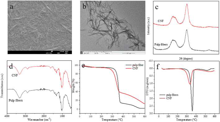
Ultrasonic disintegration considerably influences CNF production and pretreatments. However, considering the complexity of optimization to all affecting factors, this study focused on pretreatments that used [MEA][(HOA)(H2OA)]-based systems for CNF production under the pre-optimized conditions of ultrasonic disintegration. RSM was used to optimize the effect of pretreatment parameters on the yield of CNFs. The most significant parameter was identified in the optimization. The physicochemical properties of the prepared CNFs were analyzed via X-ray diffraction (XRD), scanning electron microscopy (SEM), transmission electron microscopy (TEM), Fourier transform infrared spectroscopy (FTIR), and thermogravimetric (TG) analysis. To the best of our knowledge, no report has yet been made about the optimization of PIL pretreatment based on dimeric oxalic acid anions for CNF production. This work is beneficial for the commercial application of CNFs with the use of low-cost PILs.
2 Materials and methods
2.1 Materials
Eucalyptus pulp fibers, as cellulose materials, were supplied by Zhejiang Longyou Jinchang Paper Co., Ltd (China). Ethanolamine, oxalic acid dihydrate, and anhydrous ethanol were purchased from Aladdin Reagent Co., Ltd (Shanghai) and were of analytical purity. Phosphorus pentoxide (98.5%) and phosphotungstic acid hydrate (99.0%) were purchased from Shanghai McLean Bio-technology Co.2.2 Preparation of [MEA][(HOA)(H2OA)] and its aqueous solution
IL was prepared by reacting ethanolamine and oxalic acid dihydrate as the starting material in a molar ratio of 1![[thin space (1/6-em)]](https://www.rsc.org/images/entities/char_2009.gif) :
:![[thin space (1/6-em)]](https://www.rsc.org/images/entities/char_2009.gif) 2, The resulting product was called [MEA][(HOA)(H2OA)]. Then, 63.3 g (about 0.5 mol) of oxalic acid dihydrate was dissolved in an appropriate amount of ethanol with stirring in a 500 mL round bottom flask. Thereafter, 15.3 g (about 0.25 mol) of ethanolamine was added dropwise with vigorous stirring; dropwise addition was performed in an ice water bath.15 After dropwise addition, the mixture was continuously stirred at room temperature (25 ± 1 °C) until a homogeneous and stable liquid phase was formed, followed by spin-drying at 35 °C to remove ethanol. The synthesized IL was placed in a vacuum oven (with built-in phosphorus pentoxide) at 60 °C for 48 h to remove water. Deionized water was added to the synthesized IL, and aqueous solutions of [MEA][(HOA)(H2OA)] (hereafter abbreviated as PIL–water) with different mass concentrations (10–50%) were prepared under magnetic stirring conditions.
2, The resulting product was called [MEA][(HOA)(H2OA)]. Then, 63.3 g (about 0.5 mol) of oxalic acid dihydrate was dissolved in an appropriate amount of ethanol with stirring in a 500 mL round bottom flask. Thereafter, 15.3 g (about 0.25 mol) of ethanolamine was added dropwise with vigorous stirring; dropwise addition was performed in an ice water bath.15 After dropwise addition, the mixture was continuously stirred at room temperature (25 ± 1 °C) until a homogeneous and stable liquid phase was formed, followed by spin-drying at 35 °C to remove ethanol. The synthesized IL was placed in a vacuum oven (with built-in phosphorus pentoxide) at 60 °C for 48 h to remove water. Deionized water was added to the synthesized IL, and aqueous solutions of [MEA][(HOA)(H2OA)] (hereafter abbreviated as PIL–water) with different mass concentrations (10–50%) were prepared under magnetic stirring conditions.
2.3 Preparation of CNFs
The pulp fibers were added to a 50 mL round bottom flask that contained IL water with a controlled liquid-to-solid ratio and stirred continuously under certain temperature reaction conditions. After the pretreatment reaction was completed, the pretreated fibers were washed to neutral, and the washed pretreated cellulose was uniformly dispersed in deionized water and an ultrasonic cell crusher equipped with a 25 mm-diameter cylindrical titanium alloy variable amplitude rod (JY99-IIDN, Shanghai Huyan Industrial Co., Ltd) for ultrasonic treatment.In the preliminary experiments, the operating parameters of ultrasonic disintegration, namely, ultrasonic intensity, sonication time, and pretreated cellulose content, were optimized via single-factor experimental analysis. Thus, all the experiments on CNF preparation in this work were conducted under the determined optimal conditions of ultrasonic disintegration (sonication time of 15 min, ultrasonic intensity of 1000 W, frequency of 20 kHz, and pretreated cellulose content of 0.16 wt%). To prevent the carbonization of cellulose in the high-frequency sonication environment, sonication was performed in an ice water bath. The obtained suspensions were centrifuged at 5000 rpm for 5 min. After centrifugation, the bottom sonication residue was removed and the suspensions were stored in a refrigerator at 4 °C.
The yield of CNFs in the suspension was calculated using the following equation:16
 | (1) |
2.4 Single-factor experiments
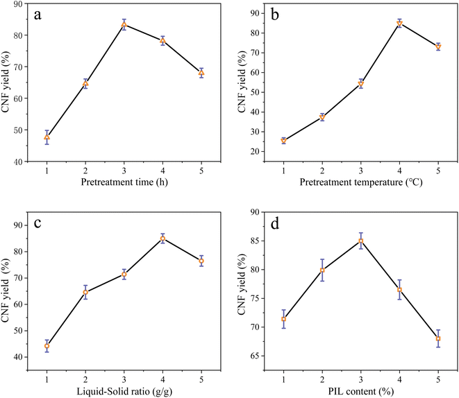
Using the CNF yield as an index, four factors, namely, pretreatment time (1, 2, 3, 4, and 5 h), pretreatment temperature (80 °C, 90 °C, 100 °C, 110 °C, and 120 °C), liquid-to-solid ratio (PIL–water-to-pulp fiber mass ratio of 20, 40, 60, 80, and 100 g g−1), and PIL content (10%, 20%, 30%, 40%, and 50%), were investigated for their effect on CNF yield. The standard deviation (SD) values were calculated after three repetitions of each reaction.2.5 Response surface optimization
The optimum reaction conditions of PIL pretreatments for CNF production were developed and optimized using RSM provided by Design-Expert 8.0.5 software. A standard RSM design tool, known as central composite design (CCD), was applied to study PIL pretreatment. The selected response value was the CNF yield. On the basis of the results of the one-factor test for CNF performance, changes in pretreatment time (A), pretreatment temperature (B), liquid-to-solid ratio (C), and PIL content (D) exerted a considerable influence on the test results and could be regarded as independent variables.17 Table S1† lists the ranges and levels of the independent variables with the actual and coded levels of each parameter. The independent variables were coded to two levels: low (−1) and high (+1). Therefore, a four-factor, three-level CCD based on the Box–Benhnken principle was developed.18 A total of 27 sets of experiments were conducted to validate the fitted quadratic polynomials. Among which, 5 sets were central replicate experiments, while the remaining 22 sets were analytical factorial experiments for estimating the experimental error. All the experiments were randomized to minimize the effect of unexplained variability on the observed response due to systematic error.2.6 Characterization of pulp fibers and the prepared CNFs
The CrI of the samples was calculated using the empirical equations of Segal19 by measuring the peak intensity of the crystalline plane (I002) and the intensity of diffraction of the amorphous material (Iam).
 | (2) |
3 Results and discussion
3.1 Single-factor experimental analysis
3.2 Results of response surface design
Response surface regression analysis was conducted on the basis of the single-factor test, with CNF yield as the evaluation index and the Box–Behnken model design.22 The results are presented in Table 1. Multiple regressions were fitted into the test data, and the quadratic multinomial regression model of Y (CNF yield) associated with four factors, namely, pretreatment time (A), pretreatment temperature (B), liquid-to-solid ratio (C), and PIL content (D), was obtained as follows:| Y = 84.43 + 3.59A + 8.22B + 2.22C − 2.13D − 0.85AB + 2.83AC + 5.95AD + 0.43BC − 2.98BD + 4.25CD − 6.04A2 − 18.23B2 − 4.98C2 − 7.39D2 | (3) |
| Run | Variables levels | Response value (CNF yield) (%) | ||||
|---|---|---|---|---|---|---|
| A | B | C | D | Experimental | Predicted | |
| 1 | 0 (3) | 0 (110) | 0 (80) | 0 (30) | 85.0 | 84.4 |
| 2 | 1 (4) | 0 (110) | −1 (60) | 0 (30) | 72.0 | 71.9 |
| 3 | 0 (3) | 0 (110) | 0 (80) | 0 (30) | 83.3 | 84.4 |
| 4 | −1 (2) | 0 (110) | −1 (60) | 0 (30) | 68.0 | 70.4 |
| 5 | 0 (3) | −1 (100) | 0 (80) | 1 (40) | 49.3 | 51.4 |
| 6 | 0 (3) | 0 (110) | 1 (100) | −1 (20) | 71.4 | 70.7 |
| 7 | −1 (2) | −1 (100) | 0 (80) | 0 (30) | 47.6 | 47.5 |
| 8 | −1 (2) | 1 (120) | 0 (80) | 0 (30) | 64.6 | 65.6 |
| 9 | −1 (2) | 0 (110) | 1 (100) | 0 (30) | 66.3 | 69.2 |
| 10 | 1 (4) | 0 (110) | 0 (80) | −1 (20) | 71.4 | 70.8 |
| 11 | 0 (3) | −1 (100) | 1 (100) | 0 (30) | 57.8 | 54.8 |
| 12 | 0 (3) | 0 (110) | 1 (100) | 1 (40) | 74.8 | 76.4 |
| 13 | 1 (4) | 1 (120) | 0 (80) | 0 (30) | 69.7 | 71.1 |
| 14 | 0 (3) | 1 (120) | −1 (60) | 0 (30) | 68.0 | 66.8 |
| 15 | 0 (3) | 0 (110) | −1 (60) | 1 (40) | 62.9 | 63.4 |
| 16 | 0 (3) | −1 (100) | −1 (60) | 0 (30) | 52.7 | 51.2 |
| 17 | 0 (3) | 0 (110) | −1 (60) | −1 (20) | 76.5 | 76.3 |
| 18 | 0 (3) | 1 (120) | 0 (80) | 1 (40) | 61.2 | 61.9 |
| 19 | 0 (3) | 1 (120) | 0 (80) | −1 (20) | 71.4 | 72.1 |
| 20 | 0 (3) | 1 (120) | −1 (60) | 0 (30) | 74.8 | 72.1 |
| 21 | 0 (3) | −1 (100) | 0 (80) | −1 (20) | 47.6 | 49.7 |
| 22 | 1 (4) | 0 (110) | −1 (60) | 0 (30) | 81.6 | 81.8 |
| 23 | 1 (4) | 0 (110) | 0 (80) | 1 (40) | 79.9 | 78.4 |
| 24 | 1 (4) | −1 (100) | 0 (80) | 0 (30) | 56.1 | 56.3 |
| 25 | −1 (2) | 0 (110) | 0 (80) | 1 (40) | 62.9 | 59.3 |
| 26 | 0 (3) | 0 (110) | 0 (80) | 0 (30) | 85.0 | 84.4 |
| 27 | −1 (2) | 0 (110) | 0 (80) | −1 (20) | 78.2 | 75.5 |
A positive sign of the pretreatment terms indicates the synergistic effect of CNF yield, while a negative sign signifies an unfavorable effect. The model (eqn (3)) has positive coefficients of A, B, C, AC, AD, BC, and CD, with a linear effect on increasing CNF yield. The coefficients of the quadratic terms of the independent variables (i.e., A2, B2, C2, and D2) in the regression model equation are all negative, indicating a negative correlation with the response values.
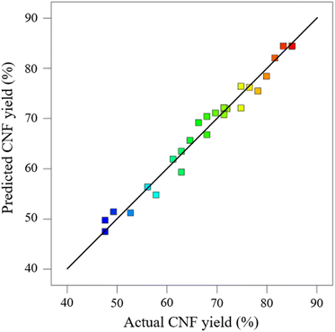
Experimental data obtained were analyzed via ANOVA to assess the significance and fitness of the quadratic reaction model and the effects of significant individual pretreatment factors and their interaction factors on CNF yield. The ANOVA results for each regression model are provided in Table 2. These results can be employed to analyze the influences of various factors on the response values. As indicated in Table 2, the linear model, the two-factor interaction linear model (2FI), and the cubic polynomial model have large P values and insignificant fitting effects, while the quadratic polynomial model exhibits better results. The cubic terms can be included in the error terms of the obtained polynomial regression equation. Among the models that can fit the response (linear, 2FI, quadratic, and cubic polynomials), the quadratic model is considered the best for generating the response through experimental design. The paraboloid represented by this regression equation has a downward opening with extreme value points that can be optimized for this test. The parameters of A–D were substituted into the quadratic term regression model (eqn (3)), and then the predicted value Y was determined (Table 1). The actual values in Table 1 agreed well with the predicted values of Y. A deviation of ±5% between the experimental and predicted values was considered acceptable.
| Source | Sum of squares | Degree of freedom | Mean square | F-value | P-value | — |
|---|---|---|---|---|---|---|
| Mean | 12![[thin space (1/6-em)]](https://www.rsc.org/images/entities/char_2009.gif) 540.05 540.05 |
1 | 12![[thin space (1/6-em)]](https://www.rsc.org/images/entities/char_2009.gif) 540.05 540.05 |
— | — | — |
| Linear | 1078.12 | 4 | 269.53 | 2.75 | 0.0540 | — |
| 2FI | 284.80 | 6 | 47.47 | 0.41 | 0.8645 | — |
| Quadratic | 1795.72 | 4 | 448.93 | 70.66 | <0.0001 | Suggested |
| Cubic | 18.99 | 8 | 2.37 | 0.17 | 0.9846 | Aliased |
| Residual | 57.25 | 4 | 14.31 | — | — | — |
| Total | 15![[thin space (1/6-em)]](https://www.rsc.org/images/entities/char_2009.gif) 774.93 774.93 |
27 | 13![[thin space (1/6-em)]](https://www.rsc.org/images/entities/char_2009.gif) 322.66 322.66 |
— | — | — |
The distribution of the actual values (Table 1) on the axes is shown in Fig. 2. The actual values were approximately distributed on the line of the predicted model equation, further indicating that the model established via RSM can explain the variation in CNF yield. ANOVA can determine the feasibility of fitting a quadratic model for pretreatment. Table S2† provides the effects of each model term (A, B, C, and D) and their interaction on the response value Y. If p < 0.05 and 0.01, then the selected model term has significance and is statistically significant; when p > 0.05, the model term is insignificant. The results indicate that when the experimental model's p < 0.05 for CNF yield, the model is significant. When the misfit term's p > 0.05, the misfit term is insignificant. The coefficient of determination (R2) is 0.9764, and the model can explain about 97% of the changes in response values, exhibiting good agreement with the actual results. The composite correlation coefficient R2 is 0.9489, indicating that about 94% of the test results were influenced by the test factors. In addition, the accuracy of the established model was verified. In the experimental results of ANOVA, the SD of the model was 2.52, and the coefficient of variation (CV) (i.e., the ratio of the estimated standard error to the mean of the observed response) was 3.7% < 10%. The lower values of SD and CV indicated that the experimental model was reliable and demonstrated high precision in the response model.23 The adequate precision value was 19.657 > 4. The preceding results further indicate that the proposed model can be used to optimize pretreatment conditions effectively.
The magnitude of the p values in Table S2† indicated that the model primary terms A and B exerted highly significant effects on the response values (p < 0.01). C and D exerted significant effects on the response values (p < 0.05). The model interaction terms AD and CD exhibited highly significant effects (p < 0.01). AC and BD had significant effects (p < 0.05), whereas AB and BC had no significant effects. The quadratic terms A2, B2, C2, and D2 presented highly significant effects (p < 0.01).
3.3 Analysis of response surface
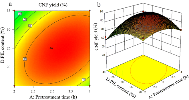
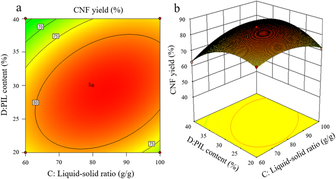
The effects of the interaction of some test factors on CNF yield are illustrated in Fig. 4–6. The contour map is the projection of the response surface on the bottom surface, and the sparsity and shape of the projection can reflect the strength of interaction among factors. When the shape is close to an ellipse, the interaction is evident. When it is close to a circle, the interaction is inevident. The slope of the response surface reflects the influence of each pretreatment factor on the response value. A high slope indicates that the interaction among factors exerts greater influence on the response value, while a gentle slope represents low influence.As shown in Fig. 3a and b, the slope of the response surface of the interaction term between pretreatment time and PIL content rate is high, and the interaction between the two exerts greater effect on CNF yield. From the contour plot, pretreatment time exhibits greater effect on the response value than PIL content rate, and the interaction between the two is significant. This finding is approximately the same as the ANOVA result of the above model regression. It is also consistent with the conclusions of Davoudpour et al.24 In the preliminary pretreatment stage, the heterogeneous diffusion of PIL in the cellulose matrix was not directly completed, and pulp fibers were not fully dissociated. With the prolongation of pretreatment time, PIL completely diffused into the cellulose matrix. This condition promoted the physical swelling of pulp fibers, increased the response surface, and promoted the cleavage of cellulose β-1,4-glycosidic bonds, shortening cellulose fibers. The response surface analysis indicated that a pretreatment time of about 3 h was ideal, but further increasing pretreatment time was not beneficial for CNF yield. As reported by Luo et al.,20 yield decreases as reaction time increases in the case of oxalic acid pretreatments. Hydrolysis has been erroneously assumed to increase the solubility of certain degradation products.
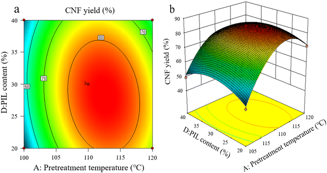
As shown in Fig. 4a and b, the interaction between pretreatment temperature and PIL content rate exerted a considerable effect on CNF yield, and the interaction between the two factors was significant, with pretreatment temperature exhibiting greater effect on the response value. At a lower pretreatment temperature, the heat energy provided by the pretreatment system was too low to break the cellulose chain effectively, resulting in an extremely low CNF yield. A pretreatment temperature of about 110 °C resulted in the best level. However, further increasing temperature was ineffective. This finding indicates that pretreatment temperature is crucial for promoting the depolymerization of cellulose chains, higher thermal energy is beneficial for the hydrolysis kinetics of pretreatment, and an increase in pretreatment temperature causes PIL to penetrate and depolymerize the amorphous zone of cellulose faster.25
As shown in Fig. 5a and b, the interaction between liquid-to-solid ratio and PIL content exerted minimal effect on CNF yield, and the interaction between the two factors was not insignificant. The variations of PIL content and liquid-to-solid ratio were detrimental to CNF yield. PIL content affected the H+ proton concentration of the pretreatment system, while liquid-to-solid ratio affected the accessibility of the pretreatment system to cellulose, exerting a weakening or facilitating effect on the shortening of cellulose during pretreatment, as reflected by the best level of CNF yield in Fig. 5. The preceding results indicate that all pretreatment conditions exert a negative effect on CNF yield at low levels or under extreme conditions. At low levels, the pretreatment system reacted poorly to cellulose with a large size after pretreatment. Under extreme conditions, cellulose was again over-hydrolyzed. Both conditions significantly reduced the yield of CNF prepared via subsequent ultrasonication disintegration. Therefore, the effective pretreatment reaction conditions should be limited within a suitable range to obtain the advantages of cost-saving, energy consumption, reaction time, and high yield. In accordance with the model analysis established by Design Expert 8.0 software, the optimal conditions were as follows: 3.15 h of pretreatment time, 111.5 °C of pretreatment temperature, liquid-to-solid ratio of 83 g g−1, and PIL content of 29%. CNF yield under these conditions was 85.96%.
3.4 Validation tests
Validation tests were conducted on basis of the predicted results of the above model. To meet operability and economy in the actual situation, the optimal test conditions were set to a pretreatment time of 3.2 h, an extraction temperature of 112 °C, liquid-to-solid ratio of 83 g g−1, and ionic liquid content of 29%. Three parallel tests were conducted to ensure the accuracy of the test results. Under these conditions, CNF yield was 86.2%, which was extremely small. The error was less than 1% relative to the predicted results, further indicating that the pretreatment conditions for optimizing CNF yield via RSM were feasible and ideal.3.5 Physicochemical properties of prepared CNFs
4 Conclusion
CNFs were successfully prepared from pulp fibers with pretreatments that used [MEA][(HOA)(H2OA)]–water, followed by ultrasonic disintegration. The operating parameters, including pretreatment time, pretreatment temperature, liquid-to-solid ratio, and PIL content, were considered the major influencing factors of CNF yield. The designed response surface experiments confirmed that the four single factors exerted significant effects on the response values. The interaction of IL content with pretreatment time, pretreatment temperature, and liquid-to-solid ratio was significant. The CNF yield of 85.0% produced by the fitted optimal pretreatment conditions was nearly identical to the actual values of 86.2%, indicating that RSM can provide a theoretical basis for optimizing CNF yield. Compared with pulp fibers, CNFs with higher CrI, length-to-diameter ratio, and thermal stability were prepared under the optimized conditions. This work revealed that pretreatment with aqueous [MEA][(HOA)(H2OA)] solutions exhibits considerable potential for high CNF yield in terms of low cost and clean production.Author contributions
Xincheng Peng: conceptualization, methodology, software, formal analysis, writing – original draft. Deqin Zhu: methodology, software, formal analysis, writing – original draft. Jingjing Liu: formal analysis, investigation. Ligang Wei: supervision, writing – review & editing. Na Liu: formal analysis, investigation. Li Wei: formal analysis, investigation. Guolin Shao: writing – review & editing. Qingda An: funding acquisition, supervision.Conflicts of interest
The authors declare that they have no known competing financial interests or personal relationships that could have appeared to influence the work reported in this paper.Acknowledgements
This work was supported by the Scientific Research Project of the Education Department of Liaoning Province of China (LJKFZ20220212).References
- S. Ling, W. Chen, Y. Fan, K. Zheng, K. Jin, H. Yu, M. J. Buehler and D. L. Kaplan, Prog. Polym. Sci., 2018, 85, 1–56 CrossRef CAS PubMed.
- H. Mahmood, M. Moniruzzaman, T. Iqbal and M. J. Khan, Curr. Opin. Green Sustainable Chem., 2019, 20, 18–24 CrossRef.
- A. H. Basta and V. F. Lotfy, Chem. Eng. Technol., 2023, 46, 837–847 CrossRef CAS.
- G. Kandhola, A. Djioleu, K. Rajan, N. Labbé, J. Sakon, D. J. Carrier and J.-W. Kim, Bioresources and Bioprocessing, 2020, 7, 19 CrossRef.
- B. Azimi, H. Maleki, V. Gigante, R. Bagherzadeh, A. Mezzetta, M. Milazzo, L. Guazzelli, P. Cinelli, A. Lazzeri and S. Danti, Cellulose, 2022, 29, 3079–3129 CrossRef CAS.
- P. F. O. Ferreira, A. L. S. Pereira, M. F. Rosa and R. S. de Santiago-Aguiar, Ind. Crops Prod., 2022, 186, 115119 CrossRef CAS.
- L. Berglund, I. Anugwom, M. Hedenström, Y. Aitomäki, J.-P. Mikkola and K. Oksman, Cellulose, 2017, 24, 3265–3279 CrossRef.
- X. Zhao, F. Cheng, Y. Hu and R. Cheng, J. Nat. Fibers, 2022, 19, 5697–5708 CrossRef CAS.
- K. Matuszek, A. Chrobok, F. Coleman, K. R. Seddon and M. Swadźba-Kwaśny, Green Chem., 2014, 16, 3463–3471 RSC.
- M. Smuga-Kogut, K. Zgórska, T. Kogut, K. Kukiełka, J. Wojdalski, A. Kupczyk, B. Dróżdż and I. Wielewska, Fuel, 2017, 191, 266–274 CrossRef CAS.
- M. G. Paredes, M. A. Mariño, R. A. Tapia, D. R. MacFarlane, K. Matuszek, D. Ruiz, M. Isaacs and P. Pavez, J. Mol. Liq., 2022, 367, 120422 CrossRef CAS.
- F. Yeganeh, N. Chiewchan and W. Chonkaew, Cellulose, 2022, 29, 2333–2349 CrossRef CAS.
- Z. Pang, P. Wang and C. Dong, Cellulose, 2018, 25, 7053–7064 CrossRef CAS.
- T. M. Hassan, M. S. Hossain, M. H. M. Kassim, M. Ibrahim, N. F. M. Rawi and M. H. Hussin, Waste Biomass Valorization, 2020, 11, 2755–2770 CrossRef CAS.
- H. Shekaari, M. T. Zafarani-Moattar and S. Faraji, J. Chem. Eng. Data, 2021, 66, 1890–1899 CrossRef CAS.
- Q. Lu, Z. Cai, F. Lin, L. Tang, S. Wang and B. Huang, ACS Sustain. Chem. Eng., 2016, 4, 2165–2172 CrossRef CAS.
- L. Ma, Y. Xu, J. Chen, C. Dong and Z. Pang, Molecules, 2023, 28, 3070 CrossRef CAS PubMed.
- L. F. Zambrano-Mite, Y. Villasana, M. L. Bejarano, C. Luciani, D. Niebieskikwiat, W. Álvarez, D. F. Cueva, D. Aguilera-Pesantes and L. M. Orejuela-Escobar, Heliyon, 2023, 9, e17258 CrossRef CAS PubMed.
- S. Sankhla, H. H. Sardar and S. Neogi, Carbohydr. Polym., 2021, 251, 117030 CrossRef CAS PubMed.
- J. Luo, K. Huang, Y. Xu and Y. Fan, Cellulose, 2019, 26, 5237–5246 CrossRef CAS.
- W. Xu, H. Grénman, J. Liu, D. Kronlund, B. Li, P. Backman, J. Peltonen, S. Willför, A. Sundberg and C. Xu, ChemNanoMat, 2017, 3, 109–119 CrossRef CAS.
- Y. Elrhayam, F. E. Bennani, M. Berradi, A. El Yacoubi and A. El Bachiri, Mater. Chem. Phys., 2023, 304, 127767 CrossRef CAS.
- W. Rasri, V. T. Thu, A. Corpuz and L. T. Nguyen, RSC Adv., 2023, 13, 19020–19029 RSC.
- Y. Davoudpour, S. Hossain, H. P. S. A. Khalil, M. K. M. Haafiz, Z. A. M. Ishak, A. Hassan and Z. I. Sarker, Ind. Crops Prod., 2015, 74, 381–387 CrossRef CAS.
- S. Wang, B. Liu, J. Liang, F. Wang, Y. Bao, C. Qin, C. Liang, C. Huang and S. Yao, Bioresour. Technol., 2023, 382, 129154 CrossRef CAS PubMed.
- C. Lin, P. Wang, Y. Liu, Y. Lv, X. Ye, M. Liu and J. Y. Zhu, ACS Sustain. Chem. Eng., 2023, 11, 8035–8043 CrossRef CAS.
- L. Liu, B. Liu, X. Li, Z. Wang, L. Mu, C. Qin, C. Liang, C. Huang and S. Yao, Ind. Crops Prod., 2023, 200, 116811 CrossRef CAS.
- Y. Zhao, J. Li, Q. Yu, K. D. Li, Q. Li, R. Zhou, R. Zhou, M. Ek and K. K. Ostrikov, Cellulose, 2023, 30, 2147–2163 CrossRef CAS.
- Y. Wang, H. Shao, H. Pan, Y. Jiang, J. Qi, Q. Chen, S. Zhang, H. Xiao, Y. Chen, S. Jia, X. Huang, L. Tu, Z. Su and J. Xie, Int. J. Biol. Macromol., 2023, 230, 123251 CrossRef CAS PubMed.
- A. A. Oun and J.-W. Rhim, Carbohydr. Polym., 2016, 150, 187–200 CrossRef CAS PubMed.
- F. Pattnaik, S. Nanda, V. Kumar, S. Naik, A. K. Dalai and M. K. Mohanty, Chem. Eng. Technol., 2022, 45, 962–970 CrossRef CAS.
- R. K. Gond, M. K. Gupta and M. Jawaid, Polym. Compos., 2021, 42, 5400–5412 CrossRef CAS.
Footnotes |
| † Electronic supplementary information (ESI) available. See DOI: https://doi.org/10.1039/d3ra06930c |
| ‡ These authors contributed equally to this paper. |
| This journal is © The Royal Society of Chemistry 2023 |

