
 Open Access Article
 This Open Access Article is licensed under a Creative Commons Attribution-Non Commercial 3.0 Unported Licence
Fabrication and characterization of a NiO–ZnO/PANI-CNTs composite for sensing of methanol in an aqueous environment†
Pham Thi Nam a,
Nguyen Thi Thoma,
Vo Thi Kieu Anha,
Huynh Le Thanh Nguyenb,
Nguyen Thi Thu Tranga,
Nguyen Thai Hoangb,
Nguyen Vân-Anhc,
Nguyen Tuan Anha,
Le Viet Hai*b and
Tran Dai Lam*a
a,
Nguyen Thi Thoma,
Vo Thi Kieu Anha,
Huynh Le Thanh Nguyenb,
Nguyen Thi Thu Tranga,
Nguyen Thai Hoangb,
Nguyen Vân-Anhc,
Nguyen Tuan Anha,
Le Viet Hai*b and
Tran Dai Lam*a
aInstitute for Tropical Technology, Vietnam Academy of Science and Technology, 18 Hoang Quoc Viet, Hanoi, Viet Nam. E-mail: dailamtran@gmail.com
bHCM City University of Science, Vietnam National University HCM City School of Chemistry and Life Science, Hanoi University of Science and Technology, 1 Dai Co Viet Road, Hanoi, Viet Nam. E-mail: lvhai@hcmus.edu.vn
cGraduate University of Science and Technology, Vietnam Academy of Science and Technology, 18 Hoang Quoc Viet, Hanoi, Viet Nam
First published on 12th December 2023
Abstract
In this study, we fabricated a composite of NiO–ZnO/PANI-CNTs on a fluorine tin oxide (FTO) electrode and examined the electrochemical sensing behavior of the modified electrode to detect methanol in aqueous solution. The structural, morphological, and electrochemical properties of the composite were characterized using various methods such as X-ray diffraction (XRD), EDS, FTIR, X-ray photoelectron spectroscopy (XPS), field-emission scanning electron microscopy (FE-SEM), transmission electron microscopy (TEM), selected area electron diffraction (SAED), and electrochemical techniques such as cyclic voltammetry (CV) and chronoamperometry (CA). The composite-based electrode showed excellent electrocatalytic activity and selectivity for methanol oxidation. The calibration equation obtained was ΔI = 0.0003 × CMeOH + 0.02811, with a high correlation coefficient of 0.9993, over a wide detection range of 0 to 500 mM. The material exhibits great potential for the fabrication of sensors to detect methanol in commercial products. Real gasoline samples have been selected to evaluate the practical performance and feasibility of this as-prepared sensor. The experimental data indicated that the recovery of gasoline samples is about 98%, indicating this to be an appropriate detection procedure for effective electrochemical determination of MeOH in real gasoline samples.
Introduction
Methanol and other volatile organic compounds pose a significant threat to living organisms and the environment.1 These compounds are widely used in the agriculture and pharmaceutical sectors, while methanol also finds its application as an organic solvent or chemical feedstock in laboratories.2Methanol is a potential alternative for engine fuel due to its high flammability, making it suitable for internal combustion engines.3 When mixed with gasoline at a ratio of 1–2%, it does not alter its chemical properties. However, when mixed at a ratio of 10–15%, it can cause severe corrosion, particularly with aluminum, which is one of the primary metals used in engine manufacturing, as well as brass, zinc, and iron.4 Besides, methanol has been illegally used in the production of cheap alcoholic beverages due to its lower price, raising the necessity for simple and efficient detection methods5 to analyze methanol in a liquid environment, especially in an aqueous medium.
Various methods are used to detect methanol, including gas chromatography-flame ionization detection (GC-FID),6 microscope FTIR spectroelectrochemistry,7 HPLC with electrochemical detection,8 and UV-vis spectroscopy.9 While some methods precisely detect alcohol quantitatively, they can be time-consuming and use expensive and bulky equipment with complicated and required procedures to examine samples.10 Therefore, these techniques do not address the requirement for rapid, precise, and portable detection of alcohols in biological and non-biological samples. Among various attempts, electrochemical sensing offers a low-cost, simple, portable, and effective method with high sensitivity and selectivity.11
The conductivity of a conductive material is proportional to the number density of charge carriers and their mobility. Conducting polymers have a large number of charge carriers but low mobility due to structural defects. However, secondary treatments like doping can increase their electrical conductivity. Combining carbon nanotubes with conducting polymers can lead to improvements in conductivity and the development of electronic devices with superior properties. Among various polymers, polyaniline (PANI) is a flexible conducting polymer commonly used in electrochemistry because it is conductive, cheap, and simple to produce.12,13 PANI-CNTs composites have found application in catalysts, nanodevices, biosensors, chemical sensors, lithium-ion batteries, and supercapacitors.14,15 Carbon nanotubes possess superior mechanical, electrical, thermal capabilities and high surface area. The presence of CNTs can enhance the conducting and mechanical properties of the composite and then improve the electrode performance16
Transition metal oxides, such as CuO,13 NiO,17 ZnO,18 and others, are also other potential candidates for improving the properties of PANI.
Nickel oxide (NiO) is a p-type semiconductor that has been extensively researched in detecting alcohol, thanks to its wide band gap and large surface area.19 Recent studies have demonstrated that NiO precipitated with NaOH exhibits high activity and stability in methanol oxidation when in an alkaline medium.20 Combining NiO nanoparticles with PANI can enhance their electrical conductivity, which results in enhanced electron transfer and electrocatalytic activity. This is because PANI nanocomposites and NiO have synergistic properties that contribute to catalytic performance and high active surface area.17 However, the use of NiO-based electrodes for alcohol sensing could be constrained by their tendency to quickly deteriorate due to microcracking and disintegration while in operation.20
Besides, the addition of chemically stable oxides, such as ZnO, is another strategy to overcome the drawbacks of NiO. Zinc oxide is a strongly n-type semiconductor, whereby a native defect, such as the oxygen vacancy (Ov) or the zinc interstitial acts as the dominant donor.21 Together with other several extra advantages like a large surface area, high electron mobility, and low cost,22 it makes ZnO becoming an ideal choice for biosensing and chemical sensing applications.23 The combination of ZnO and NiO can also overcome the poor electrical conductivity of ZnO.24 It also generates a p–n NiO–ZnO heterojunction and band bending in the depletion layer at the interface of p-type NiO and n-type ZnO clusters. These may improve the sensing capability of ZnO.25 The use of NiO/ZnO in butanol sensing,26 ZnO/PANI composite for detecting methanol vapor had been reported.27 Ahmed et al. reported the use of Ni-modified electrode for electrocatalytic oxidation of methanol in alkaline medium.28
Our study explores the effectiveness of using a mixed NiOOH–Ni(OH)2/ZnO nanoclusters and PANI-CNTs hybrid to modify FTO electrodes for methanol sensing in aqueous environments. The entire sensor fabrication process was electrochemical, which involved electropolymerization to form PANI-CNTs hybrids, followed by the electrodeposition and overoxidation of Ni based species and ZnO mixture nanoparticles on the sensing interfaces. As shown in this research, the composite exhibited good linearity within the working range of methanol concentration of up to 500 mM. The composite modified electrode has high selectivity for methanol in aqueous media and possesses potential for fabrication of electrochemical sensors for direct analysis of methanol in fuel.
Experimental
Chemicals and materials
Aniline (ANI, 99%) was from ACROS Organics™ and was purified by distillation before use. Sodium hydroxide (NaOH, 99%), zinc chloride hexahydrate (ZnCl2·6H2O > 99%), and nickel(II) chloride hexahydrate (NiCl2·6H2O > 98%) were also obtained from Acros Organics. Multi walled carbon nanotubes (CNTs > 95%, 10–20 μm long, the inner diameter of ca. 5 nm and the outer diameter of 6–14 nm) from Sigma-Aldrich. Other chemicals such as methanol (MeOH, 99.9%), ethanol (EtOH, 99%), isopropyl alcohol (IPA >90%), acetone, and sulfuric acid (H2SO4, 99%) were purchased from Fisher-Scientific. All chemicals are in analytical grade and were used as received except aniline.FTO electrodes (TEC8, resistance of 8 Ωm cm−1, the size of 10 × 50 × 2.2 mm) were from Dyesol (Australia). Double distillated water was used in all experiments.
The electrochemical setup
Electrochemical experiments were carried out on Gamry Interface 1010T potentiostat (USA). A typical three-electrode system was used, in which the working electrode was a pristine FTO electrode or modified electrode using a PANI-based composite; the counter electrode was a platinum mesh, and the reference electrode was an Ag/AgCl electrode (3.5 M KCl).Fabrication of composite modified FTO electrodes
The different layers of the modified composite were electrodeposited onto the FTO substrates by cyclic voltammetry (CV). The procedure was described in our previous work13 with several modifications. Before the electrodeposition process, the FTO electrode surfaces were cleaned with distilled ethanol and water in an ultrasonic bath for 15 minutes and then dried at 120 °C. The electrode preparation protocol comprises three main steps.In the first step, a PANI-CNTs composite was electrosynthesized onto the FTO substrate (active area of 1.0 cm2) using a CV technique. The scanning potential ranges from −0.5 V to 1.3 V for 10 cycles at a scan rate of 30 mV s−1. The electrolyte solution included 0.1 M aniline, 0.5 M H2SO4 in a mixture of H2O/IPA (v/v = 1/1), and 0.01 mg mL−1 CNTs, which were previously well dispersed by sonication. After that, the PANI-CNTs composite coated FTO (denoted as PANI-CNTs/FTO) was rinsed carefully with distilled water, then with ethanol, and dried at room temperature for 30 minutes.
In the second step, Ni and Zn metal particles were simultaneously electrodeposited onto the PANI-CNTs/FTO electrode using a CV method (potential range of −0.3 to −0.9 V with 20 cycles and scan rate of 100 mV s−1) from a solution containing 0.025 M ZnCl2 and 0.025 M NiCl2 in a 0.1 M KCl supporting electrolyte solution. The obtained electrodes were rinsed with distilled water and then allowed to dry at room temperature for 30 minutes.
In the final step, the surface functionalized metals (Ni–Zn) were electro-oxidized to their oxides (NiO–ZnO) in a NaOH 0.1 M aqueous solution by a CV method (the potential range of 0.0 V to 0.8 V with 5 cycles and a scan rate of 50 mV s−1). The modified electrodes (denoted as NiO–ZnO/PANI-CNTs/FTO) were rinsed with deionized water and then allowed to dry at room temperature for further voltammetric measurement. An NiO/PANI-CNTs/FTO (without the presence of ZnO) were also generated for the comparison purposes.
Structural and morphological characterizations
X-ray diffraction (XRD) patterns were recorded with D8 Advance Eco (Bruker, Germany). The radiation source used was Cu Kα1 with a wavelength of 1.5406 Å, and the patterns were recorded between 20 and 70° at a scan rate of 2.4° min−1. The X-ray tube voltage was set at 40 kV, and the X-ray tube current was set at 40 mA. Fourier transform infrared (FTIR) spectra were obtained using a LUMOS II FT-IR (Bruker, Germany). Energy-dispersive X-ray (EDS) measurement were carried out by a SU-8000 microscope (Hitachi, Japan), Field-emission scanning electron microscopic (FE-SEM) images were analyzed using an JSM-6480LV equipment (JEOL, Japan). Transmission electron microscopic (TEM) and the selected area electron diffraction (SAED) images were recorded in a multipurpose JEM 2100 electron microscope (JEOL, Japan) operating at 200 kV.X-ray photoelectron spectroscopy (XPS) was conducted using a X-ray photoelectron spectrometer (K-Alpha, Thermo Fisher Scientific) that was fitted with a hemispherical electron energy analyzer and a non-monochromatized Al(Kα) X-ray source. The photons emitted by the X-ray source had an energy of 1486.6 eV, and the resolution was 1.0 eV, obtained from the full-half width at the maximum of the Au(4f7/2) core level line. To account for surface-charging phenomena, the BE of the C(1s) core level was adjusted to 284.5 eV. The XPS peaks were separated into several components, and the quantitative analysis was performed by subtracting the Shirley background baseline.29 The developed curve-fitting software (CasaXPS processing software) enables the adjustment of several parameters, including the Gaussian\Lorentzian ratio, the full width at half maximum (FWHM), as well as the position and intensity of the contributions. These parameters were optimized using to obtain the most accurate fit to the experimental data.30
Detection of methanol using a NiO–ZnO/PANI-CNT/FTO electrode
A cyclic voltammetry method was utilized to evaluate the capability of the NiO–ZnO/PANI-CNT/FTO electrode for detecting methanol within a potential range of 0.0 to 0.8 V at a scan rate of 100 mV s−1. The electrocatalytic activity of the electrode in the electro-oxidation of methanol present in samples was performed in a 0.1 M NaOH-supporting electrolyte solution.The sensing characteristics of the MeOH sensors, such as linear range, sensibility, limit of detection, and selectivity, were analyzed with the addition of MeOH at various concentrations. The selectivity of the sensor was tested using a chronoamperometry technique (CA) with different interferences, such as EtOH, IPA, and acetone. The specific operating conditions were expressed in certain experiments.
To evaluate the practical performance and feasibility of the as-prepared sensor, we try to examine the real samples of alcoholic beverages and RON A95 gasoline. It is well known that gasoline also poses serious economic and environmental problems in many countries and deliberate illegal fuel formulations related to MeOH adulteration are the main reasons for unqualified and unsafe gasolines.
Results and discussion
Electrochemical synthesis of NiO–ZnO/PANI-CNTs composite on an FTO electrode
Fig. 1 displays the results of the PANI-CNTs and PANI synthesis using the CV technique, that gives a green coating film on the FTO electrodes. | ||
| Fig. 1 Cyclic voltammograms of the electropolymerization of (A) PANI-CNTs and (B) PANI onto FTO electrodes, at a scan rate of 30 mV s−1, and a potential range from −0.5 V to 1.3 V, 10 cycles; (C) the first cycle lines and (D) the fifth cycle lines of the electrodeposition processes. | ||
At the first sight, the shape of Fig. 1A and B is similar with typical peaks of the aniline oxidation to form polyaniline and two peak couples that characterize for the oxidation–reduction of the obtained polyaniline. Furthermore, increasing the number of cycles, the oxidation peaks shifted to positive potential whereas the reduction peaks shifted to the negative potential. It implies that the formation of polyaniline film onto the FTO substrates.31 In addition, their peak height increased with the increase of number of potential cycles, suggested that the films were conductive and also electroactive.32
In the first cycles (Fig. 1C), the diagrams of both materials were almost identical because it consisted of 3 stages: the cleaning and activation of FTO33 (from −0.5 V to 1.1 V); the oxidation of aniline molecules was at above 1.1 V to generate cation radicals which further react together to form polymer chains34, and the reduction of PANI (corresponding to Epc1 and Epc2 reduction peaks). It seems that carbon nanotubes (CNTs) did not contribute much to the electropolymerization of aniline in the first scan.
From the second scan, the current intensity in the case of the PANI-CNTs composite synthesis was higher than that of pristine PANI (Fig. 1D). It can be explained as follows: When several polymer chains were generated, CNTs fibers in the aqueous medium could be adsorbed onto the PANI polymer matrix because the conjugated system of the CNTs sidewall and of PANI could form the π-stacking interactions.35 Besides, because CNTs has higher conductivity than PANI, CNTs enhanced the conductivity of the PANI matrix when combined with the PANI.
Overall, a highly conductive PANI-CNTs composite with better conductivity and electroactivity was successfully synthesized on the FTO substrate.
The electrodeposition of a nickel and zinc oxide mixture was then performed onto the PANI-CNTs electrode surface using electrochemical techniques. The same experiment was carried out with nickel for comparison (Fig. 2). The processes consisted of two steps: electrolysis of the metals on the electrode surface (Fig. 2A and B) and oxidizing these metals to oxides (Fig. 2C and D).
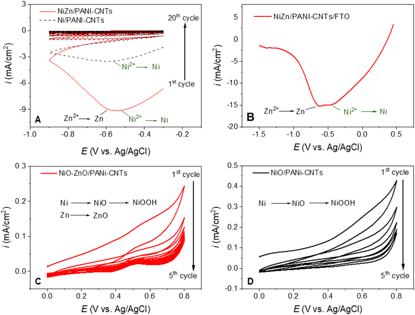 | ||
| Fig. 2 (A) Nickel–zinc electrodeposition on PANI-CNTs/FTO at 100 mV s−1; (B) the reduction of Ni2+ and Zn2+ on PANI-CNTs at 50 mV s−1; (C) electro-oxidation of Ni–Zn to oxides, and (D) the electro-oxidation of Ni to oxide (at a scan rate of 50 mV s−1). | ||
In Fig. 2A, the first cycle in the synthesis of NiZn/PANI-CNTs (red line) has a peak at ca. −0.55 V that can be assigned to the simultaneous reduction of Ni2+ and Zn2+ ions to Ni–Zn alloy. After the first scan, the current density doped sharply, suggesting that the metal loading on the composite surface was saturated.36
Fig. 2B presents the result of the reduction of Ni2+ and Zn2+ on a PANI-CNTs/FTO electrode in a wider potential range and a smaller scan rate of 50 mV s−1. It showed clearly a reduction peak at ca. −0.45 V that is assigned to the reduction of Ni2+ to Ni, and a peak at ca. −0.6 V that is ascribed to the reduction of Zn2+ to Zn.
Fig. 2C and D indicates the oxidation of Zn0 and Ni0 on the PANI-CNTs composite in the next stage. The oxidation of Ni0 in an alkaline environment produce NiOOH species36 but at a quite small content so that it is hard to observe the peak of Ni3+ reduction in the case of Ni/PANI-CNTs composite (Fig. 2C). It is noticed that the lower current intensity of the oxidation process in the case of ZnNi/PANI-CNTs and the occurrence of the anodic and cathodic peaks at around 0.5 V and 0.4 V are referred to the Ni(II)/Ni(III) reversible transformation. The quick drop of the current intensity in the subsequent cycles implies that the metals were mostly oxidized in the first and second scans. The low density of current indicates the effect of the Zn element in the PANI-CNTs composite on the Ni oxidation.37
The obtained results suggest that the metal oxide clusters include a small amount of NiOOH species beside NiO–ZnO form, in which NiOOH plays a role of catalytic active sites whereas NiO–ZnO clusters acts as a supporter as being discussed in the below sections.
The characterizations of the NiO–ZnO/PANI-CNTs composite
Fig. 3 displays the electrochemical behavior of NiO–ZnO/PANI-CNTs/FTO using CV measurement of the material-modified electrode in an electrolyte solution of 0.1 M NaOH at a scan rate of 50 mV s−1 for 7 cycles. A similar experiment on NiO/PANI-CNTs/FTO was also carried out for comparison. | ||
| Fig. 3 The electrochemical activity of Ni3+/Ni2+ during oxidation–reduction of the NiO nanoparticles in the potential range of 0 ÷ 0.7 V vs. Ag/AgCl in 1 M NaOH solution, the scan rate of 50 mV s−1. | ||
The cyclic voltammograms indicate a redox pair of the Ni(III)/Ni(II) couple, with an anodic peak and a cathodic peak at +0.47 V and +0.31 V, respectively, that was also similar to the work reported by Nagashree et al.28. The peaks correspond to the oxidation to higher oxidative species Ni(III) and vice versa, and the equation presented as below:38
| Ni(OH)2 + OH− ↔ NiOOH + H2O + e− | (1) |
The existence of nickel oxyhydroxide was also proved in other characterization.
There was no indication of the involvement of ZnO during the change in the oxidation state of nickel species. However, a higher peak current (ipa at 0.470 V) was observed, suggesting that a larger active surface area was available for NiOOH formation.38 It corresponds to the fact that ZnO with a large specific area increases the loading of active NiOOH, creating more active sites due to the larger surface area. As a result, the charge transfer capability was improved.39 This result implies that the electrode with the presence of both Ni and Zn elements may be more effective in electrochemical activity than the one with only presence of Ni based species.
The EDS spectra of NiO–ZnO/PANI-CNTs and NiO/PANI-CNTs composites are presented in Fig. 4. It demonstrates the presence of C, N, O, Ni, Na, S, K and Cl elements (Fig. 4A). The abundant content of carbon was from CNTs and the polymeric backbone of PANI, N was from nitrogen atoms in PANI composition, S and O came from the dopant HSO4−. Additionally, O could be in NiO and NiOOH species. The presence of K, Na and Cl impurities happened during the synthetic process of the composites in the electrolyte that consisted of KCl or NaOH. For clarity, these impurities were omitted in the spectrum of NiO–ZnO/PANI-CNTs composite (Fig. 4B). It points out that beside the C, O, N and S elements that were due to the PANI-CNTs matrix, nickel and zinc elements were also present. The higher atomic percentage of Ni in this case could be thanks to the effect of ZnO as discussed in electrochemical behavior of the composite in the 0.1 M NaOH solution.
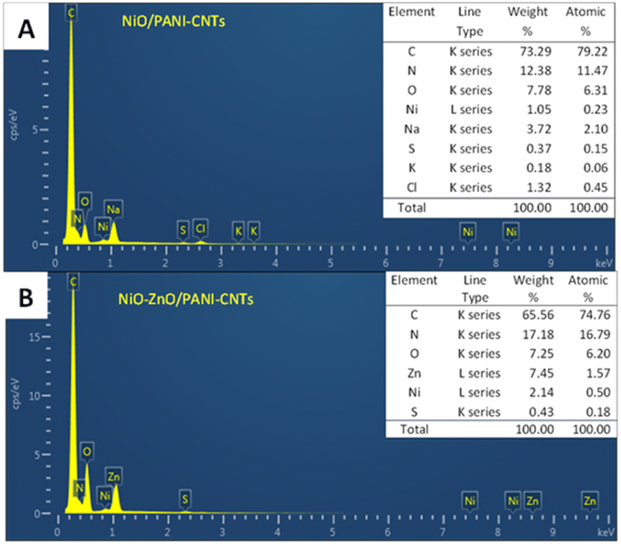 | ||
| Fig. 4 EDS spectra of (A) NiO/PANI-CNTs and (B) NiO–ZnO/PANI-CNTs. | ||
However, the amount of Ni and Zn element were quite small (less that 1% of atomic percentage in both cases). Consequently, there was almost no signals of NiOOH (JCPDS 006-0075), NiO (JCPDS 78-0643) or ZnO (JCPDS 36-1451) in XRD analysis (see Fig. S1 in ESI†). An extra reason for hardly observing the peaks of these species is the overlap of them with the diffraction characteristic peaks of the FTO substrate (JCPDS 00-005-0467).40
The morphology of the NiO–ZnO/PANI-CNTs surface was determined using SEM and TEM/SAED analysis (Fig. 5). The SEM image of NiO/PANI-CNTs was also presented as a comparison.
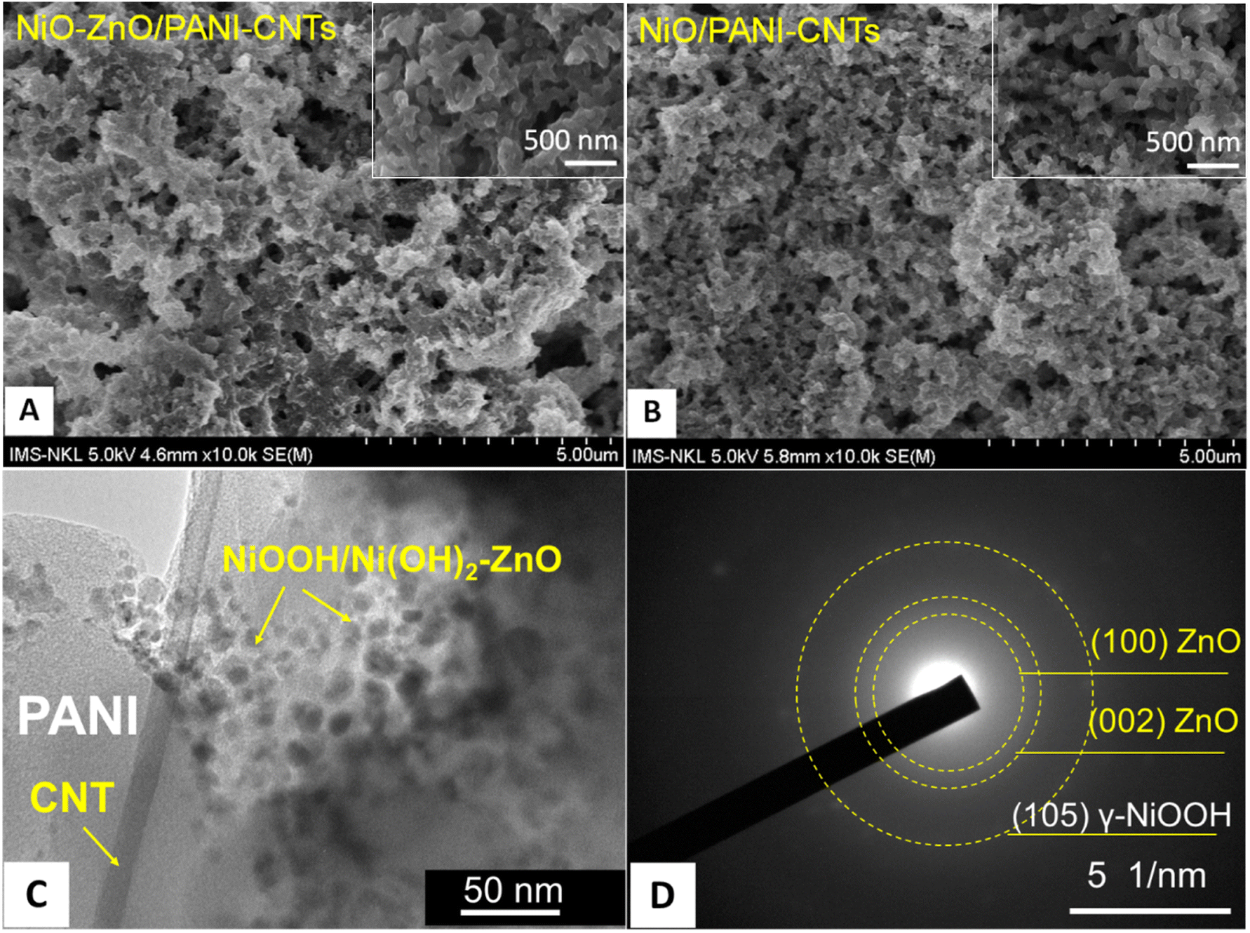 | ||
| Fig. 5 SEM images of (A) the NiO–ZnO/PANI-CNTs/FTO electrode and (B) the NiO/PANI-CNTs/FTO electrode, (C) TEM image and (D) SAED of NiO–ZnO/PANI-CNTs. | ||
As shown in Fig. 5(A) and (B), both composites have a porous structure that is an important property for sensing activity because it reduces the diffusion length of target molecules into the composite surface.41 It can be seen that NiO–ZnO/PANi-CNTs film has fibers of 100 nm size that were interconnected, forming a highly porous structure. In addition, there were the presence of aggregated clusters in the composite structure. The incorporation of NiOOH–Ni(OH)2/ZnO on PANI-CNTs to create numerous clusters on the composite. The SEM images of pure PANI and PANI-CNTs are expressed in Fig. S2 (see ESI†) demonstrates typical fibered structure of PANI and CNTs whereas the short-rod morphological property of pure PANI was exhibited.
The shape of NiOOH/Ni(OH)2–ZnO clusters can be seen in the TEM image of the composite (Fig. 5C). The results showed complicated shapes that could be assigned to the mixed shape of ZnO and the NiOOH/Ni(OH)2 mixture with the size in a range of 20–30 nm. The existence of a fiber with diameter of about 20 nm points out the presence of CNTs in the composite matrix.
The selected area electron diffraction (SEAD) patterns of NiO–ZnO/PANI-CNTs in Fig. 5D demonstrated the (100) and (002) planes relevant to hexagonal wurtzite structure of ZnO (JCPDS 036-1451) and the (105) plane associated with the γ-NiOOH (JCPDS 6-75).
The TEM/SAED pattern confirms the presence of γ-NiOOH and ZnO nanoparticles in the nanocomposite.
Fig. 6 shows the FTIR spectra of the two composites, NiO–ZnO/PANI-CNTs, and NiO/PANI-CNTs, pointing out the distinct peaks that are associated with the functional group vibration of PANI in the emeraldine form: 3300 cm−1 (–N–H– stretching); 1588 cm−1 and 1494 cm−1 (C![[double bond, length as m-dash]](https://www.rsc.org/images/entities/char_e001.gif) C stretching of the benzenoid ring); 1309 (C–N–C stretching mode of the second arylamine); 1153 cm−1 (C–H in-of-plane bending of the quinoid ring); 830 cm−1 (in-of-plane bending). The band at around 602 cm−1 could be assigned to the Ni–O stretching vibration.36 The Zn–O stretching frequency,42 whose has a range of 400 cm−1–500 cm−1 was not in the measurement range. Fig. 7 presents the X-ray photoelectron spectroscopy (XPS) that provides further information of the chemical composition and the valence state of each element on the surface of the NiO–ZnO/PANI-CNTs composite. Table 1 shows the binding energies and relevant bonding assignments.
C stretching of the benzenoid ring); 1309 (C–N–C stretching mode of the second arylamine); 1153 cm−1 (C–H in-of-plane bending of the quinoid ring); 830 cm−1 (in-of-plane bending). The band at around 602 cm−1 could be assigned to the Ni–O stretching vibration.36 The Zn–O stretching frequency,42 whose has a range of 400 cm−1–500 cm−1 was not in the measurement range. Fig. 7 presents the X-ray photoelectron spectroscopy (XPS) that provides further information of the chemical composition and the valence state of each element on the surface of the NiO–ZnO/PANI-CNTs composite. Table 1 shows the binding energies and relevant bonding assignments.
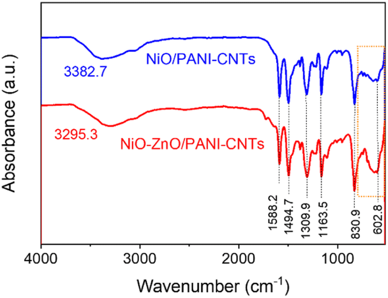 | ||
| Fig. 6 FTIR of NiO/PANI-CNTs and NiO–ZnO/PANI-CNTs composites. | ||
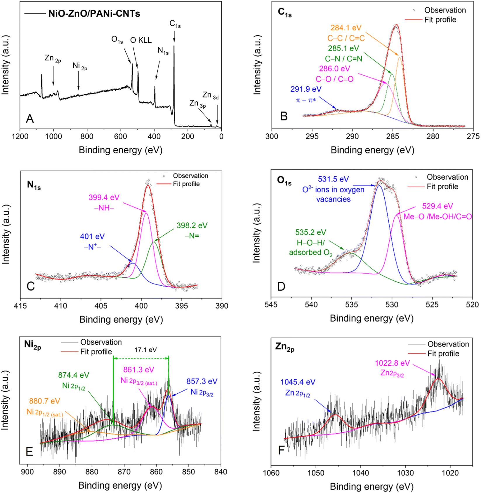 | ||
| Fig. 7 (A) XPS scan spectrum of the NiO–ZnO/PANI-CNTs material and XPS spectra of (B) C 1s, (C) N 1s, (D) O 2p, (E) Ni 2p and (F) Zn 2p. | ||
| Peak | Bonding | Binding energy (eV) | Peak | Bonding | Binding energy (eV) |
|---|---|---|---|---|---|
| C 1s 1 | C–C/CC |
284.1 | O 1s 2 | O2− ions in oxygen vacancy | 531.5 |
| C 1s 2 | C–N/CN |
285.1 | O 1s 3 | H–O–H/adsorbed O2 | 532.2 |
| C 1s 3 | C–O/CO/O–CO |
286.0 | Ni 2p3/2 1 | Ni–O | 857.3 |
| C 1s 4 | π–π* | 291.9 | Ni 2p3/2 2 (sat.) | Ni–O | 861.3 |
| N 1s 1 | N– |
398.2 | Ni 2p1/2 1 | Ni–O | 874.4 |
| N 1s 2 | N–H | 399.4 | Ni2p1/2 2 (sat.) | Ni–O | 880.7 |
| N 1s 3 | –N+– | 401.0 | Zn 2p3/2 | Zn–O | 1022.8 |
| O 1s 1 | Me–O/Me–OH | 529.4 | Zn 2p1/2 | Zn–O | 1045.4 |
The full range spectrum (Fig. 7A) exhibits the presence of the elements: carbon (C 1s ∼284 eV), nitrogen (N 1s ∼400 eV), (O 1s ∼530 eV, O KLL ∼500 eV), nickel (Ni 2p ∼850–890 eV) and zinc (Zn 2p ∼1020–1050 eV). This result again confirms the existence of these elements in the prepared materials. However, the intensity of Ni and Zn was small, implying the low content of these elements in the composite films.
Fig. 7B indicates the C 1s spectrum of PANI-CNTs composite. This spectrum can be deconvoluted into four peaks with binding energies centered at 284.1 eV (non-oxygenate carbon C–C/CC in aromatic ring), 285.1 eV (C–N/CN) and 286.0 eV, which are oxygenated carbon C–O/CO/O–CO due to the formation of hydroquinone and benzoquinone during the PANI electrosynthesis43. The signal at 291.9 eV is ascribed to the π–π* “shake-up” band.44
The core level spectrum of N 1s in PANI is deconvoluted into three subpeaks at 398.2 eV (–N), 399.4 eV (–NH) and 401.0 eV (–N+–) (Fig. 7C). Similarly, the O 1s spectrum in Fig. 7D is the composition of the three subpeaks at 529.4 eV, 531.5 eV, and 535.2 eV. The high binding energy component at 535.2 eV is attributed to the presence of loosely bound oxygen on the NiO–ZnO/PANI-CNTs composite surface, which can be adsorbed H2O or adsorbed O2, chemisorbed or dissociated oxygen, or species of the OH type on the surface of the oxides.45 The lower binding energy O 1s peak at 529.4 eV can be attributed to the lattice O2− (i.e. Me–O/C–O–Me, Me–OH, where Me is either Ni or Zn).46 The peak at approximately 531.5 eV corresponds to the O2− ions in the oxygen-deficient regions within the oxide bonding matrix,21 which are associated with oxygen vacancies. The intensity of this component is related to the concentration of oxygen vacancies,47 which have the lowest formation energy among all the donor-like defects. The large oxygen deficiency in the surface layer, or in other words, the enrichment of Zn or Ni, contributes to the stability of the composite under operating conditions. Moreover, the oxygen vacancy easily combines with chemically adsorbed O or OH species, which play an important role in the sensory responses.
In Fig. 7E, the subpeaks located at binding energies of 856.3 eV and 874.4 eV correspond to the spin–obit split Ni 2p3/2 and Ni 2p1/2, whereas other small broad signals at higher binding energies of 861.3 eV and 880.7 eV are satellite peaks.48 The peak located at 856.3 eV identifies a NiOOH/Ni(OH)2 mixture49 because the characteristic multiple feature of Ni(II) 2p state often locates at the binding energy less than 855 eV.25,41 Moreover, the difference between the two major states of spin–obit slitting was 17.1 eV, that characterizes for a Ni(III) state while that of Ni(II) state should be about 17.8 eV.41 It is possible that there is a small quantity of NiO, but it cannot be completely dismissed due to its low content.
Finally, Fig. 7F presents the high-resolution XPS spectrum of Zn 2p of NiO–ZnO/PANI-CNTs, displaying the spin–orbit split Zn 2p3/2 and Zn 2p1/2 signals at 1022.8 eV and 1045.4 eV, respectively. These signals are typical of Zn(II) in the materials and the spin–orbit splitting falls within the standard reference value range for ZnO, which is 22.6 eV, as reported in the literature.21
The obtained results from morphological and structural characterizations show the presence of a complicated nanocluster on the PANI-CNTs composite. These nanoclusters contain a NiOOH/Ni(OH)2 mixture, combined with ZnO. The porous composites provide significant advantages for the fabrication and operation of electrochemical sensors.
Detection of methanol on the NiO–ZnO/PANI-CNTs/FTO electrode
Fig. 8 illustrates the electrochemical behavior of the NiO–ZnO/PANI-CNTs/FTO electrode in which the oxidation of methanol was evaluated using CV measurements in a solution containing 0.1 M NaOH and various concentrations of methanol, in the potential range of 0.0 to 0.8 V at the scan rate of 100 mV s−1. It can be observed that the increase in MeOH concentration results in an increase in the current intensity. The calibration equation is ΔI (mA) = 0.0003 × CMeOH + 0.02811 with the square of the correlation coefficient of 0.9993, in a wide detection range of 0 to 500 mM with a LOD of 0.0194 mM (S/N = 3). Notice that in the case of NiO/PANI-CNTs/FTO, the linear relationship was in in the MeOH concentration range of 200–500 mM. | ||
| Fig. 8 Cyclic voltammetric responses of (A) NiO–ZnO/PANI-CNTs/FTO electrode and (B) NiO/PANI-CNTs/FTO electrode in a solution containing various concentrations of methanol and 0.1 M NaOH (0 to 0.8 V, 100 mV s−1) and the oxidation peak density vs. methanol concentration and the square of the correlation coefficient (R2) corresponding to the corresponding electrode (inset). | ||
Though the sensitivity of NiO–ZnO/PANI-CNTs/FTO and NiO/PANI-CNTs/FTO electrodes toward methanol detection were very similar, the selectivity with different interferences of the NiO–ZnO/PANI-CNTs/FTO electrode exhibited better performance, as demonstrated in Fig. 9.
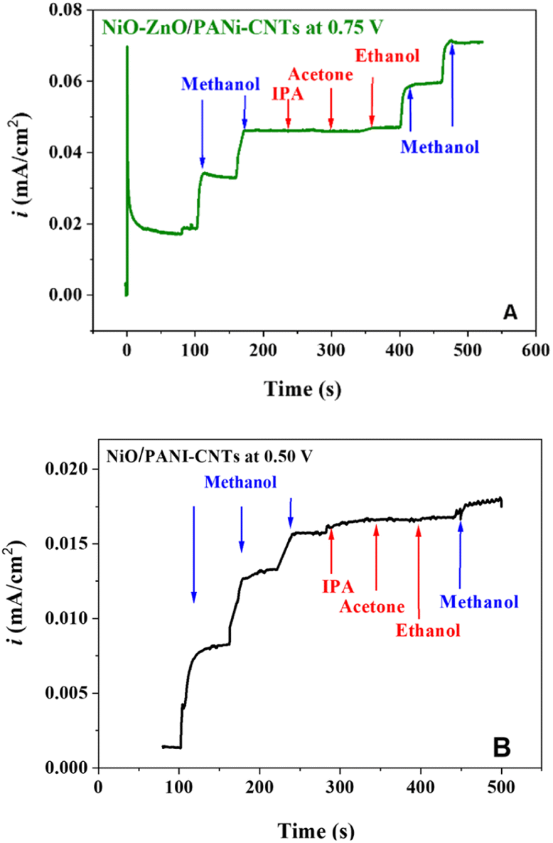 | ||
| Fig. 9 Interference tests on (A) NiO–ZnO/PANi-CNTs/FTO and (B) NiO/PANi-CNTs/FTO with the methanol concentration of 50 mM and 10 mM of each interference in 0.1 M NaOH. | ||
It can be observed that the interferences such as EtOH, acetone, and isopropyl alcohol (IPA) do not change the signal of MeOH detection. Besides, the signal responses after interference spikes were still significant in the case of NiO–ZnO/PANI-CNTs/FTO.
The supposed mechanism for detection of methanol was proposed in our previous work,36 in which there was the formation of γ-NiIIIOOH species on the composite surface at an oxidation potential higher than 0.5 V (vs. Ag/AgCl, see Fig. 6). These species are the active sites where the irreversible oxidation of MeOH occurs:
| NiOOH + MeOH → Ni(OH)2 + MOR intermediates | (2) |
The involvement of zinc(II) species was not observed during the oxidation state change of nickel. This could be due to the fact that ZnO only functions as a support due to its large surface-to-volume ratios, high chemical stability, biocompatibility, and electromobility. ZnO provides several advantages like increase of the active sites (i.e., NiIIIOOH) for methanol adsorption, thus promoting methanol oxidation activity and efficient charge separation due to the formation of a p–n heterojunction between p-type NiO and n-type ZnO as illustrated in Fig. 10.
 | ||
| Fig. 10 Schematic illustration of the heterojunction formation between p-type NiO and n-type ZnO. | ||
The role of each component can be described as follows: when the NiO/ZnO composite is exposed to alcohol, the released electrons return to ZnO, decreasing the resistance, while the holes in p-type NiO combine with the released electrons, reducing the hole concentration and increasing the electron concentration. This process shortens the potential barrier height of the depletion layer, weakening the diffusion of carriers and further decreasing the sensor resistance.
Moreover, with the addition of ZnO, the number of oxygen vacancies increases together with the formation of the Zn–O and Ni–O bonds at the Zn–O–Ni interface, leading to a considerable number of oxygen vacancies. Besides, the destruction of the local equilibrium of the crystal structure occurs due to the different ionic radii of zinc and nickel, resulting in an increase in internal stress in the main lattice, and oxygen vacancies need to be formed to release the stress.50 The presence of oxygen vacancies facilitates the adsorption of methanol molecules and MOR species (eqn (2)), and effectively increases the exposed active sites. The high catalytic selectivity is attributed to the accessibility of methanol molecules on the catalyst surface through the oxygen vacancies.51
Table 2 presents the comparison of the NiO–ZnO/PANI-CNTs/FTO electrode with different electrodes in methanol and other alcohol sensing in an aqueous environment.
| Electrodes | Detection method | Sensitivity (μA cm−2 mM−1) | Limit of detection (LOD) | Linear range | Ref |
|---|---|---|---|---|---|
| a p–n junction materials.b Ni(II)–MHP: N-5-methoxysalicylaldehyde, N′-2-hydroxyacetophenon-1,2 phenylenediimino nickel(II) complex. | |||||
| Ni(II)-MHP/RGO/CPEb | DPV | — | 0.68 μM | 2.0–100.0 μM | 52 |
| 100.0–1000.0 μM | |||||
| ZnO nanoparticles | I–V techniques | 0.9554 | 0.11 mM | 0.25 mM–1.8 M | 53 |
| PMMA-Gr-CNTs | I–V techniques | 13.491 | 0.39 nM−1 | 1.0 nM to 1.0 M | 54 |
| α-Fe2O3–CdSe/Nafion/GCEa | I–V techniques | 0.2744 | 0.041 ± 0.005 mM | 0.2 up to 800 mM | 55 |
| PTh/α-Fe2O3/Nafion/GCE | I–V techniques | 0.0563 | 1.59 mM | 5–100 mM | 56 |
| 0.793 | 100 to 1000 mM | ||||
| CuO/PANI-Gr | CV | 0.8 | — | 20–300 mM | 13 |
| 0.2 | 300–1300 mM | ||||
| NiOOH/PANI-CNTs | CV | 0.3774 | 0.323 mM | 1–20 mM | 36 |
| 0.0892 | 6.974 mM | 20–500 mM | |||
| NiOOH/PANI-Gr | CV | 1.5 | 0.290 mM | 1–20 mM | |
| 0.2 | 4.166 mM | 20–100 mM | |||
| NiO–ZnO/PANI-CNTs | CV | 0.3 | 0.0194 mM | 50 μM–500 mM | This work |
Detection of MeOH in real samples
To determine the practical performance and feasibility of the above sensor, the determination of MeOH from real sample (gasoline) was examined. NiO–ZnO/PANI-CNTs was chosen as sensor electrode for further evaluations with real sample. Fig. 11 presents the CV curves of NiO–ZnO/PANI-CNTs electrode with 3 RON A95 real gasoline samples. The data are summarized in Table 3. The recovery of the samples can be found at least 98%, indicating that the detection procedure can be used as an effective electrochemical determination of MeOH in the real gasoline samples. | ||
| Fig. 11 CV curves of NiO–ZnO/PANI-CNTs electrode with RON A95 real gasoline samples. | ||
Conclusions
A composite of bimetal oxide with PANI-CNTs was synthesized via electrodeposition. Various techniques, such as SEM, TEM, XPS, XRD, and CV, were used to identify the materials and reveal the crystalline structure, morphological structure, and electrochemical behavior of the NiO–ZnO/PANI-CNTs material. The methanol sensing capabilities of the composite were investigated through electrochemical measurements. The results showed that the composite has the ability to electrocatalyze the oxidation of methanol and significantly increase the response current with good anti-interference properties. In case of real gasoline samples, experimental results indicated 98% recovery of samples, indicating the potential application of these sensors for the real gasoline samples.Conflicts of interest
There are no conflicts to declare.Acknowledgements
This work was financially supported by Vietnam Academy of Science and Technology for funding under grant # NCXS 01.01/22-24.Notes and references
- J. V. Ashurst and T. M. Nappe, Methanol Toxicity, StatPearls Publishing, Treasure Island (FL), 2020 Search PubMed.
- F. Knorr, D. G. Sanchez, J. Schirmer, P. Gazdzicki and K. A. Friedrich, Appl. Energy, 2019, 238, 1–10 CrossRef CAS.
- J. M. Encinar, A. Pardal and N. Sánchez, Fuel, 2016, 166, 51–58 CrossRef CAS.
- S. Pandey, Heat Transfer, 2022, 51, 3334–3352 CrossRef.
- J. P. J. D. Oliveira, M. B. S. Emeterio, A. C. D. Sá, L. L. Paim and M. D. Valle, Proceedings, 2020, 42(1), 5 Search PubMed.
- J. A. Joseph, S. Akkermans and J. F. M. Van Impe, ACS Omega, 2022, 7, 24121–24133 CrossRef CAS PubMed.
- Z.-Y. Zhou, N. Tian, Y.-J. Chen, S.-P. Chen and S.-G. Sun, J. Electroanal. Chem., 2004, 573, 111–119 CAS.
- A. Santasalo-Aarnio, Y. Kwon, E. Ahlberg, K. Kontturi, T. Kallio and M. T. M. Koper, Electrochem. Commun., 2011, 13, 466–469 CrossRef CAS.
- K. Wrobel, D. M. Rodríguez, F. J. A. Aguilar and K. Wrobel, Talanta, 2005, 66, 125–129 CrossRef CAS PubMed.
- S. A. Hashemi, S. Bahrani, S. M. Mousavi, N. Omidifar, M. Arjmand, K. B. Lankarani, M. Shokripour and S. Ramakrishna, Anal. Chim. Acta, 2022, 1194, 339407 CrossRef CAS PubMed.
- D.-S. Park, M.-S. Won, R. N. Goyal and Y.-B. Shim, Sens. Actuators, B, 2012, 174, 45–50 CrossRef CAS.
- S. Konwer, A. K. Guha and S. K. Dolui, J. Mater. Sci., 2013, 48, 1729–1739 CrossRef CAS.
- N. X. A. Nguyen, L. Viet Hai, T. K. N. Nguyen, T. N. Pham, T. T. Nguyen, L. T. N. Huynh, V. V. Pham, T. T. T. Nguyen, N. Thai Hoang and T. Dai Lam, RSC Adv., 2021, 11, 28573–28580 RSC.
- E. Frackowiak, V. Khomenko, K. Jurewicz, K. Lota and F. Béguin, J. Power Sources, 2006, 153, 413–418 CrossRef CAS.
- G. Kaur, A. Kaur and H. Kaur, Polym.–Plast. Technol. Mater., 2021, 60, 504–521 Search PubMed.
- S. Tajik, H. Beitollahi, F. G. Nejad, I. S. Shoaie, M. A. Khalilzadeh, M. S. Asl, Q. Van Le, K. Zhang, H. W. Jang and M. Shokouhimehr, RSC Adv., 2020, 10, 37834–37856 RSC.
- I. Chakraborty, N. Chakrabarty, A. Senapati and A. K. Chakraborty, J. Phys. Chem. C, 2018, 122, 27180–27190 CrossRef CAS.
- A. M. Mohammed, S. S. Mohtar, F. Aziz, M. Aziz and A. Ul-Hamid, J. Environ. Chem. Eng., 2021, 9, 105065 CrossRef CAS.
- S.-J. Li, N. Xia, X.-L. Lv, M.-M. Zhao, B.-Q. Yuan and H. Pang, Sens. Actuators, B, 2014, 190, 809–817 CrossRef CAS.
- N. Spinner and W. E. Mustain, Electrochim. Acta, 2011, 56, 5656–5666 CrossRef CAS.
- J. Das, S. K. Pradhan, D. R. Sahu, D. K. Mishra, S. N. Sarangi, B. B. Nayak, S. Verma and B. K. Roul, Phys. B, 2010, 405, 2492–2497 CrossRef CAS.
- M. Bumika, M. Kumar Mallick, S. Mohanty, S. K. Nayak and A. K. Palai, Mater. Lett., 2020, 279, 128473 CrossRef CAS.
- Y. Kang, F. Yu, L. Zhang, W. Wang, L. Chen and Y. Li, Solid State Ionics, 2021, 360, 115544 CrossRef CAS.
- S. Ikram, J. Jacob, U. Rehman, K. Mahmood, A. Ali, A. Ashfaq, N. Amin, K. Mehboob, Y. Ali, M. I. Arshad, M. A. U. Nabi, K. Javaid, M. S. Hussain and S. A. Tahir, Ceram. Int., 2021, 47, 13934–13938 CrossRef CAS.
- S. Bai, J. Han, J. C. Meng, L. Sun, J. Sun, Y. Zhao, P. Tang, R. Luo, D. Li and A. Chen, Sens. Actuators, B, 2021, 339, 129720 CrossRef CAS.
- X. Chen, T. Liu, L. Han and X.-T. Yin, Sens. Actuators, B, 2023, 390, 134011 CrossRef CAS.
- A. Sáaedi, P. Shabani and R. Yousefi, J. Alloys Compd., 2019, 802, 335–344 CrossRef.
- K. L. Nagashree and M. F. Ahmed, J. Solid State Electrochem., 2010, 14, 2307–2320 CrossRef CAS.
- J. E. Castle and A. M. Salvi, J. Vac. Sci. Technol., A, 2001, 19, 1170–1175 CrossRef CAS.
- G. H. Major, N. Fairley, P. M. A. Sherwood, M. R. Linford, J. Terry, V. Fernandez and K. Artyushkova, J. Vac. Sci. Technol., A, 2020, 38, 061203 CrossRef CAS.
- D.-j. Guo and H.-l. Li, J. Solid State Electrochem., 2005, 9, 445–449 CrossRef CAS.
- J. Zhang, L.-B. Kong, B. Wang, Y.-C. Luo and L. Kang, Synth. Met., 2009, 159, 260–266 CrossRef CAS.
- A. Sayah, F. Habelhames, A. Bahloul and A. Boudjadi, J. Mater. Sci.: Mater. Electron., 2021, 32, 10692–10701 CrossRef CAS.
- A. Korent, K. Žagar Soderžnik, S. Šturm and K. Žužek Rožman, J. Electrochem. Soc., 2020, 167, 106504 CrossRef CAS.
- Z. Spitalsky, D. Tasis, K. Papagelis and C. Galiotis, Prog. Polym. Sci., 2010, 35, 357–401 CrossRef CAS.
- N. Thi Kim Ngan, N. Thi Thom, N. N. X. An, L. V. Hai, P. Thi Nam, H. Le Thanh Nguyen, P. Van Viet, N. Thi Thu Trang, N. T. Hoang and D. L. Tran, J. Electrochem. Soc., 2021, 168, 107509 CrossRef.
- S. L. Medway, C. A. Lucas, A. Kowal, R. J. Nichols and D. Johnson, J. Electroanal. Chem., 2006, 587, 172–181 CrossRef CAS.
- V. Strano and S. Mirabella, RSC Adv., 2016, 6, 111374–111379 RSC.
- G. Vijaya Prasath, K. S. Usha, M. Karuppaiah, G. Ravi and P. Krishnan, J. Sol-Gel Sci. Technol., 2022, 104, 198–210 CrossRef CAS.
- A. Korjenic and K. S. Raja, J. Electrochem. Soc., 2019, 166, C169–C184 CrossRef CAS.
- N. Jayababu, M. Poloju, J. Shruthi and M. V. R. Reddy, Mater. Sci. Semicond. Process., 2019, 102, 104591 CrossRef CAS.
- M. N. Siddique, T. Ali, A. Ahmed and P. Tripathi, Nano-Struct. Nano-Objects, 2018, 16, 156–166 CrossRef CAS.
- S. Golczak, A. Kanciurzewska, M. Fahlman, K. Langer and J. J. Langer, Solid State Ionics, 2008, 179, 2234–2239 CrossRef CAS.
- V. H. Nguyen and J.-J. Shim, J. Spectrosc., 2015, 2015, 297804 Search PubMed.
- P. Ahuja, S. Ujjain, I. Arora and M. Samim, ACS Omega, 2018, 3, 7846–7855 CrossRef CAS PubMed.
- N. Jayababu, S. Jo, Y. Kim and D. Kim, Ultrason. Sonochem., 2021, 71, 105374 CrossRef CAS PubMed.
- M. Chen, X. Wang, Y. H. Yu, Z. L. Pei, X. D. Bai, C. Sun, R. F. Huang and L. S. Wen, Appl. Surf. Sci., 2000, 158, 134–140 CrossRef CAS.
- M. C. Biesinger, L. W. M. Lau, A. R. Gerson and R. S. C. Smart, Phys. Chem. Chem. Phys., 2012, 14, 2434–2442 RSC.
- N. Weidler, J. Schuch, F. Knaus, P. Stenner, S. Hoch, A. Maljusch, R. Schäfer, B. Kaiser and W. Jaegermann, J. Phys. Chem. C, 2017, 121, 6455–6463 CrossRef CAS.
- J. Zhang and J. Li, Nanomater., 2022, 12(3), 433 CrossRef CAS PubMed.
- C. Liu, F. Yang, A. Schechter and L. Feng, Adv. Sens. Energy Mater., 2023, 2, 100055 CrossRef.
- A. Benvidi, M. Dehghan Tezerjani, A. Dehghani Firouzabadi, M. Rezaeinasab, M. Mazloum Ardakani, A. H. Kianfar and M. Sedighipoor, J. Chin. Chem. Soc., 2018, 65, 603–612 CrossRef CAS.
- M. Faisal, S. B. Khan, M. M. Rahman, A. Jamal and M. M. Abdullah, Appl. Surf. Sci., 2012, 258, 7515–7522 CrossRef CAS.
- M. M. Rahman, M. A. Hussein, K. A. Alamry, F. M. Al Shehry and A. M. Asiri, Talanta, 2016, 150, 71–80 CrossRef CAS PubMed.
- M. M. Abdullah, M. Faisal, J. Ahmed, F. A. Harraz, M. Jalalah and S. A. Alsareii, J. Electrochem. Soc., 2021, 168, 057525 CrossRef CAS.
- F. A. Harraz, M. Faisal, M. Jalalah, A. A. Almadiy, S. A. Al-Sayari and M. S. Al-Assiri, Appl. Surf. Sci., 2020, 508, 145226 CrossRef CAS.
Footnote |
| † Electronic supplementary information (ESI) available. See DOI: https://doi.org/10.1039/d3ra06850a |
| This journal is © The Royal Society of Chemistry 2023 |